US5063516A - Smart power driver system for a motor vehicle - Google Patents

Smart power driver system for a motor vehicle Download PDF

Info

Publication number
US5063516A
US5063516A US07/396,206 US39620689A US5063516A US 5063516 A US5063516 A US 5063516A US 39620689 A US39620689 A US 39620689A US 5063516 A US5063516 A US 5063516A
Authority
US
United States
Prior art keywords
fault
self test
status
power driver
providing
Prior art date
Legal status (The legal status is an assumption and is not a legal conclusion. Google has not performed a legal analysis and makes no representation as to the accuracy of the status listed.)
Expired - Lifetime
Application number
US07/396,206
Inventor
Saad A. Jamoua
Melvin J. Sarnowsky
Karl R. Heck
Current Assignee (The listed assignees may be inaccurate. Google has not performed a legal analysis and makes no representation or warranty as to the accuracy of the list.)
Ford Global Technologies LLC
Original Assignee
Ford Motor Co
Priority date (The priority date is an assumption and is not a legal conclusion. Google has not performed a legal analysis and makes no representation as to the accuracy of the date listed.)
Filing date
Publication date
Application filed by Ford Motor Co filed Critical Ford Motor Co
Priority to US07/396,206 priority Critical patent/US5063516A/en
Assigned to FORD MOTOR COMPANY reassignment FORD MOTOR COMPANY ASSIGNMENT OF ASSIGNORS INTEREST. Assignors: JAMOUA, SAAD A., SARNOWSKY, MELVIN J.
Assigned to FORD MOTOR COMPANY reassignment FORD MOTOR COMPANY ASSIGNMENT OF ASSIGNORS INTEREST. Assignors: HECK, KARL R.
Application granted granted Critical
Publication of US5063516A publication Critical patent/US5063516A/en
Assigned to FORD GLOBAL TECHNOLOGIES, INC. A MICHIGAN CORPORATION reassignment FORD GLOBAL TECHNOLOGIES, INC. A MICHIGAN CORPORATION ASSIGNMENT OF ASSIGNORS INTEREST (SEE DOCUMENT FOR DETAILS). Assignors: FORD MOTOR COMPANY, A DELAWARE CORPORATION
Anticipated expiration legal-status Critical
Expired - Lifetime legal-status Critical Current

Links

Images

Classifications

    • GPHYSICS
    • G01MEASURING; TESTING
    • G01RMEASURING ELECTRIC VARIABLES; MEASURING MAGNETIC VARIABLES
    • G01R31/00Arrangements for testing electric properties; Arrangements for locating electric faults; Arrangements for electrical testing characterised by what is being tested not provided for elsewhere
    • G01R31/005Testing of electric installations on transport means
    • G01R31/006Testing of electric installations on transport means on road vehicles, e.g. automobiles or trucks
    • G01R31/007Testing of electric installations on transport means on road vehicles, e.g. automobiles or trucks using microprocessors or computers

Definitions

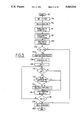
  • steps 108, 110, 112, 114, 116, and 118 a determination is made of exactly which power driver 12 1-8 has indicated a new fault, and the corresponding injector status counter (ISC 1-8 ) is updated. More specifically, index INJ is first set to 1 and the least significant bit (LSB) of register ISF 70 is compared to a logic 1 as shown by steps 108 and 110. Each affirmative comparison indicates that a new fault has occurred. The corresponding counter ISFC 1-8 is then checked for its maximum count (99 in this example) and incremented by 1 (see steps 112 and 114).

Abstract

An electrical power driver system with fault monitoring provision for both a self test mode and a normal operating mode. During the self test mode, the power driver is momentarily actuated during test intervals and its output compared to a predetermined value for providing self test fault indications. Each power driver is sampled and an indication provided of whether the fault is new or old in addition to providing a count of faults. During normal operation, monitoring circuitry provides indications of a plurality of fault types including over temperature, open circuit, short to ground, and short to voltage. A determination is made of whether each fault type is new or old and a count of faults provided. Output formatting provides indications of fault type, fault count, and whether the fault is intermittent or hard.

Description

BACKGROUND OF THE INVENTION
The field of the invention relates to electrical power drivers with fault monitoring provisions.
Electrical power drivers commonly employ a switching transistor coupled between a voltage source and a load such as an electronically actuated fuel injector. In response to an actuating signal, the switching transistor couples the voltage source to the load through its dynamic impedance. Various attempts have been made to incorporate diagnostics with the power driver. For example, U.S. Pat. No. 4,589,401 issued to Karim et al discloses a power driver having diagnostic capability. Current sensing through the load is coupled to a microcomputer for inferring either short circuit or open circuit fault conditions. More specifically, when current is detected during the absence of an actuating signal, the microcomputer infers a short circuit condition. Similarly, when current is not sensed during an actuating signal, the microcomputer infers an open circuit condition.
Another example of a power driver having some form of fault diagnosis is provided by a Siemens device designated as SMT 12 SMART-SIPMOS™. Sensing circuitry is coupled to a FET transistor for providing indications of open circuit, short circuit, over temperature, and under voltage conditions. These fault indications are provided on a status output pin by toggling the input and monitoring changes in status output. Additional external circuitry is required to infer the fault type from the input changes and the corresponding changes in status output.
The inventors herein have recognized numerous disadvantages with the fault detection approaches described above. For example, the inventors herein contend that these prior approaches do not provide a servicing technician with indications of whether a particular fault is new, or old, or intermittent. Further, the inventors herein contend that relatively sophisticated external microcomputer programming is required to infer a particular fault type from the prior devices. These disadvantages are particularly severe in a modern automobile environment having numerous electronically actuated devices and complex electrical interconnections or cabling. Accordingly, service technicians commonly replace allegedly defective components which are actually not defective. Further, technicians are often unable to repair intermittent failures.
SUMMARY OF THE INVENTION
It is therefore an object of the present invention to provide an electronic switching module with fault detection including detection of intermittent faults.
The above and other disadvantages are overcome, and object achieved, by providing both an apparatus and method for determining faulty operation in an electronic power driver coupled to an electronically actuated device. In one particular aspect of the invention, the method comprises the steps of: generating test intervals; actuating the power driver for a predetermined time during each of the test intervals; sampling an electrical power output of the driver during each of the self test intervals; and determining from the sampling step whether there is a new fault indication which did not occur during a previous one of the test intervals. An advantage is thereby obtained of providing accurate indications of intermittent faults which was not heretofore possible.
In another aspect of the invention, the apparatus comprises: at least one switching means responsive to an actuating signal for coupling electrical power to a load, the switching means including monitoring means for monitoring a plurality of electrical operating parameters of the switching means and for providing a corresponding plurality of fault type indications, the monitoring means also latching each of the plurality of fault type indications as they occur; sampling means for periodically sampling the plurality of fault type indications from the switching means; detection means responsive to the sampling means for providing an indication of when each of the plurality of fault type indications is a new fault; and formatting means for providing an indication of fault type for each of the switching means and also providing an indication of intermittent fault operation.
The above aspect of the invention provides an advantage of accurately determining intermittent operation. Another advantage provided is that an indication of each fault type and the number of times each such type occurred is provided thereby aiding the service technician in accurately locating and repairing the fault condition.
DESCRIPTION OF THE DRAWINGS
The objects and advantages described herein are better understood by reading the following description of an example of an embodiment in which the invention is used to advantage, referred to herein as the Description of the Preferred Embodiment, with reference to the drawings wherein:
FIG. 1A is a block diagram of a power switching module in which the invention is used to advantage;
FIG. 1B is a table of various status outputs of the embodiment shown in FIG. 1A;
FIG. 1C is a table showing how the status output is encoded by the switching module shown in FIG. 1A to provide the exact fault type;
FIG. 2 is a block diagram of a system wherein the embodiment shown in FIG. 1A is used to advantage;
FIG. 3 illustrates various memory locations shown for the system shown in FIG. 2 which are utilized to advantage during self test operations;
FIGS. 4A and 4B illustrate various memory locations of the system shown in FIG. 2 for storing various fault types during normal operation;
FIG. 5 illustrates various process steps performed by the system illustrated in FIG. 2 during self test operations;
FIG. 6A and 6B illustrate various process steps performed by the system shown in FIG. 2 during normal operations;
FIG. 7 illustrates the output format of the system shown in FIG. 2; and
FIGS. 8A and 8B illustrate various process steps for performing the output formatting shown in FIG. 7.
DESCRIPTION OF THE PREFERRED EMBODIMENT
Referring first to FIG. 1, a block diagram of smart power driver 12 including temperature operating monitors is shown. Field effect transistor (FET) 14 is shown having output electrodes coupled between a voltage source (VBAT) and an output pin for applying power to a load (such as a fuel injector shown in FIG. 2). Charge pump 20 is shown actuating the gate of FET 14 in response to an input signal. Sensing circuitry 26 is shown coupled to FET 14 for providing indications of a short to ground, an open, or a short to voltage. This circuitry comprises conventional circuitry well known to those skilled in the art. For example, a short to ground is indicated by providing a sensing resistor (not shown) having a fraction of load current fed therethrough. Voltage comparators (not shown) coupled across the sensing resistor then provide an indication of a short to ground. An open circuit indication is indicated by a voltage comparator (not shown) coupled across the output electrodes of FET 14. Thermal sensing indicates an over temperature condition by monitoring the leakage current through a transistor (not shown) coupled to FET 14. Voltage level converter 30 monitors the voltage drop across the load and in response provides a logic 1 output if the voltage drop is greater than half of VBAT.
Latch 32 is a 4-bit asynchronous latch which individually latches short to ground, open, short to voltage, and over temperature fault conditions as they occur. Encoder 40 encodes the four fault indications into binary bits S3 and S4. The encoding scheme is shown in FIG. 1C. Encoder 40 also provides binary signal S1 having a logic 1 state when any of the four fault indications are present.
Multiplexer 42 receives fault status S1, fault codes S3 and S4, and output feedback S2. As described in greater detail later herein, in response to select A (SELA) and select B (SELB), multiplexer 42 couples either S1, S2, S3, or S4 to status output circuitry 46 which then provides a single buffered output at the status pin. More specifically, the status provided at the status pin is shown in FIG. 1B as a function of SELA and SELB. When SELA is high, and SELB transitions from low to high, a reset pulse is generated to reset latch 32. After the reset pulse, the occurrence of any fault condition will be set into latch 32.
A block diagram illustrating the use of smart power drivers 12 in a fault monitoring system is shown in FIG. 2 wherein like numerals refer to like elements shown in FIG. 1. For the particular example illustrated herein, power drivers 121-8 are shown driving respective fuel injectors 1-8. It is noted, however, that the invention described herein may be used to advantage with any number of power drivers 12 driving load other than fuel injectors such as, for example, solenoid valves, electric motors, and relays. The status output from power drivers 121-8 are shown coupled to microcomputer 50 and keep alive memories 52 via interface module 54 and busline 56. The structure and operation of keep alive memories 52 is described later herein with particular reference to FIGS. 3 and 4A-4B. Microprocessor 50 is shown communicating with keep alive memories 52 and interface module 54 via conventional data in/out line 58, instruction transfer line 60 and read/write line 62. For the particular example shown herein, microcomputer 50 actuates injectors 1-8 via bank 1 and bank 2 commands on respective lines 64 and 66.
In general terms, which are described in greater detail later herein with particular reference to FIGS. 5 and 6A-6B, there are two basic modes of fault monitoring--a self test mode and a performance monitoring mode. The self test mode occurs each time the ignition key is actuated. The performance monitoring mode continuously occurs during the vehicular operation.
The structure of keep alive memory 52 is now described with reference to FIGS. 3 and 4A-4B. For ease of illustration, the structure of that portion of keep alive memory 52 relating to self test is first described. The portion of keep alive memory 52 relating to the performance monitoring mode is described later herein. With respect to the self test mode, keep alive memory 52 includes injector status flag (ISF) register 70, previous injector status flag (PISF) register 72, injector status flag history (ISFH) register 74, and injector status flag counters (ISFC1-8)) 76, 78, 80, 82, 84, 86, 88, and 90. More specifically, ISF 70 is here shown as an 8-bit register wherein the eight output feedback signals S21-8 from respective fuel injectors 1-8 are concurrently stored. For the particular example illustrated herein, the least significant bit position of ISF register 70 stores output feedback signal S21 from injector 1, and the most significant bit position stores output feedback signal S28 from injector 8. Previous injector status flag register 72 is shown storing the previous output feedback signals PS21-8 from respective injectors 1-8. Output feedback signals PS21-8 are the eight output feedback signals S21-8 from the previous self test cycle.
ISFH 74 is here shown as an 8-bit register storing a history of eight output feedback fault signals HS21-8 for respective injectors 1-8. During any self test cycle, a fault indication on any of the output feedback signals S21-8 results in a setting of the corresponding one of the HS21-8 signals to a logic 1. Stated another way, whenever any of the HS21-8 signals in register ISFH 74 is a logic 1, an indication is given that the corresponding power driver 121-8 provided a failure indication during a self test interval.
Continuing with FIG. 3, eight injector status fault counters ISFC1-8 are shown. These counters are designated in FIG. 3 as ISFC1 76, ISFC 2 78, ISFC 3 80, ISFC 4 82, ISFC 5 84, ISFC 6 86, ISFC 7 88, and ISFC 8 90. Each counter ISFC1-8 counts faults provided by the corresponding power driver 121-8 for each self test cycle. Accordingly, the resultant status flag count CS21-8 from the respective ISFC1-8 counter represents the number of times one of the corresponding power drivers 121-8 has provided a failure indication during a self test cycle.
Referring now to FIG. 5, a description of the operation of power drivers 121-8, microcomputer 50, keep alive memories 52, and interface module 54 during the self test mode is now described. The process steps are illustrated via numbered blocks representative of operations sequenced by microcomputer 50.
Start step 92 indicates initiation of a self test cycle in response to operator actuation of the vehicle ignition. The fault contents S21-8 of injector status fault register (ISF) 70 are transferred to previous injector fault status register (PISF) 72 as indicated by step 94. During step 96, SELA and SELB are set low to read output feedback values S21-8 from respective power drivers 121-8. During step 97, power drivers 121-8 apply power to respective injectors 1-8 for a predetermined time period. The resulting output feedback values S21-8, which are proportional to the power actually applied to injectors 1-8, are stored in a temporary storage register (not shown). Each power driver 121-8 then removes power from respective injectors 1-8 and the resulting output feedback values S21-8 are stored in another temporary storage location (see step 98).
During step 100, the "on" and "off" values of S21-8 from each temporary storage location are compared in an exclusive nor operation to determine the presence of any faults. Stated another way, each stored S21-8 value corresponding to the "on" state should be a logic 1, and each stored S21-8 value corresponding to the "off" state should be a logic 0. Otherwise, a fault indication is provided. For each resulting fault indication from a power driver 121-8, a logic 1 is stored in a corresponding bit location of register ISF 70. These stored fault values are then updated such that only new fault values (i.e. fault indications which did not occur during a previous self test cycle) remain stored in ISF 70. More specifically, during step 102, each bit of register ISF 70 is compared with the corresponding bit of register PISF 72. Fault indications which existed during previous self test cycle are then removed from register ISF 70 such that only new faults remain as shown by step 104. Similarly, injector status fault history register (ISFH) 106 is updated by a simple logic "or" operation in step 74. Thus, a logic 1 in a particular bit location of register ISFH 74 indicates a fault from the corresponding power driver 121-8 was provided during at least one self test interval.
During steps 108, 110, 112, 114, 116, and 118 a determination is made of exactly which power driver 121-8 has indicated a new fault, and the corresponding injector status counter (ISC1-8) is updated. More specifically, index INJ is first set to 1 and the least significant bit (LSB) of register ISF 70 is compared to a logic 1 as shown by steps 108 and 110. Each affirmative comparison indicates that a new fault has occurred. The corresponding counter ISFC1-8 is then checked for its maximum count (99 in this example) and incremented by 1 (see steps 112 and 114).
The next power driver 121-8 is then evaluated by shifting register ISF 70 to the right (i.e. towards the least significant bit location) and the injector index INJ is incremented by 1 during steps 116 and 118. A determination is then made as to whether faults associated with all eight power drivers 121-8 have been evaluated (step 118) and, if not, steps 110, 112, 114, and 116 are resequenced. When all injectors have been evaluated, SELA and SELB are set high for reading fault/no fault value S1 during the subsequent performance monitoring mode (see steps 120 and 122).
In accordance with the description provided above, at the end of a self test cycle, register ISF 70 contains new fault indications from the last self test cycle, register ISFH 74 contains an indication of whether any fault has occurred during any self test cycle, and counter ISFC1-8 contain a count of the number of faults provided by each power driver 121-8. Thus, a technician will be informed of failures including intermittent failures which where not heretofore possible. For example, the technician will realize that a fault occurred at some time during a self test interval by examining register ISFH, and then determine that the fault was intermittent by examining the contents of the corresponding fault counter ISFC.
The structure and operation of the performance monitoring mode of operation are now described with reference to the memory structure shown in FIGS. 4A and 4B and the process steps shown in FIG. 6. Referring first to the portions of keep alive memory 52 shown in FIGS. 4A and 4B, injector status register (ISR) 130 is here shown storing the fault/no fault values (S11-8) from respective power driver 121-8. The least significant bit location of ISR 130 is shown storing value S11 from power driver 121 and the most significant bit location is shown storing value S18 from power driver 128. Previous injector status register (PISR) 132 is shown storing fault/no fault values PS11-8 from the previous performance monitoring cycle.
Eight fault type registers FT1 136, FT 2 138, FT 3 140, FT 4 142, FT 5 144, FT6 146, FT7 148, and FT8 150 are shown. Each fault type register FT1-8 stores the four fault types (1 bit each) from respective power drivers 121-8. The four fault types are: over temperature OT, short to voltage STV, short to ground STG, and open circuit OC. Eight fault history registers are also shown: FHT 1 156, FHT 2 158, FHT 3 160, FHT 4 162, FHT 5 164, FHT 6 166, FHT7 168, and FHT8 170. Each fault history register FHT1-8 stores the fault history of the four fault types from each power driver 121-8.
Referring now to FIG. 4B in general terms, each fault type (OC, STG, STV, and OT) is counted in a separate counter corresponding to each power driver. More specifically, eight open circuit counters are shown: OCC 1 176, OCC 2 178, OCC 3 180, OCC 4 182, OCC 5 184, OCC 6 186, OCC 7 188, and OCC 8 190. Each of the OCC1-8 counters provides a count of the number of open circuit failures from the corresponding power driver 121-8. For example, COC1 represents the count of open circuit failures from power driver 121.
Similarly, eight short to ground counters are shown: STGC 1 206, STGC 2 208, STGC 3 210, STGC 4 212, STGC 5 214, STGC 6 216, STGC 7 218, and STGC 8 220. Each open circuit counter STGC1-8 provides a count (CSTG1-8) of the number of short to ground failures from the corresponding power driver 121-8. Continuing with FIG. 4B, eight short to voltage counters are shown: STVC 1 236, STVC 2 238, STVC 3 240, STVC 4 242, STVC 5 244, STVC 6 246, STVC 7 248, STVC 8 250. Each short to voltage counter STVC1-8 counts the number of short to voltage failures (CSTV1-8) from respective power drivers 121-8. Eight over temperature counters are also shown in FIG. 4B: OTC 1 266, OTC 2 268, OTC 3 270, OTC 4 272, OTC 5 274, OTC 6 276, OTC 7 278, and OTC 8 280. Each over temperature counter OTC1-8 provides a count (COT1-8) of the number of over temperature failures provided by respective power drivers 121-8.
The performance monitoring mode of operation is now described with respect to the process steps sequenced by microcomputer 50 shown in FIGS. 6A & 6B. It is noted that the performance monitoring described herein continues during normal operation of power drivers 121-8 such that the outputs S11-8, S31-8, and S41-8 are sampled at predetermined time intervals. Beginning with process step 230, SELA and SELB are set high to read fault/no fault values S11-8 from power drivers 121-8. Fault/no fault values S11-8 are stored in appropriate bit locations of injector status register (ISR) 130 during process step 232. ISR 130 is then compared on a bit by bit basis to PISR 132 to determine whether there is any change in fault information (see process step 234). During process step 236 ISR 130 is updated in response to the above comparison such that it contains only new fault information. If any new faults are indicated (see step 238), a determination of the exact fault type is then made during the following process steps. More specifically, during step 240, SELA is set low and SELB is set high to read encoded fault values S41-8 from respective power drivers 121-8. Encoded fault values S41-8 are stored in respective bit locations 0-7 of temporary storage register S4R (not shown) as indicated by step 242. SELA is then set high and SELB is then set low during step 244 for reading encoded fault value S31-8 from respective power drivers 121-8. In step 246, encoded fault values S31-8 are stored in respective bit locations 0-7 of temporary storage register S3R (not shown).
Injector index INJ is set to 1 in step 248 for initially processing the fault information received from power driver 121. During step 250, the least significant bit of ISF register 70 [ISF(0)] is examined to determine whether there was a self test fault indication during the previous self test cycle. In the event a self test failure is indicated from the particular power driver now being evaluated (power driver 121 in this example), fault type information received from that particular power driver is deemed to be unreliable and, accordingly, a fault type determination is not made (see step 250).
During step 252 the least significant bit location of ISR 130 is evaluated to determine whether the corresponding fault/no fault value S11-8 indicates a fault for the corresponding power driver 121-8. If a fault is indicated, then encoded values S3, and S4 are decoded during the subsequent process steps to determine the exact type of fault. More specifically, if both S3 and S4 are low for the particular power driver being evaluated, than the decoded fault type is a short to voltage STV (see steps 254, 256, and 258). When S3 is at a low level and S4 is at a high level for the particular power driver being evaluated, than a short to ground STG is indicated (see steps 254, 256 and 260). When S3 is decoded at a high level, and S4 is decoded at a low level, than an over temperature fault type is indicated for the particular power driver being evaluated (see steps 254, 262, and 264). When S3 and S4 are both decoded at a high level, than an open circuit fault type is indicated for the particular power driver being evaluated (see steps 254, 262, and 266).
For a short to ground STG fault type, the second bit location of fault type register FT1-8 and fault history type register FHT1-8 are updated for the particular power driver being evaluated (see steps 270 and 272). The short to ground counter for that particular register (STGC1-8) is then incremented if that register has not reached its maximum count of 99 (see steps 274 and 276).
As shown by steps 280, 282, 284, and 286 when a short to voltage STV1-8 fault type is indicated, the appropriate fault type register (FT1-8) and fault history type register (FHT1-8) are updated. The short to voltage counter (STVC8) corresponding to the appropriate power driver is also incremented provided it has not reached its maximum count.
Similarly, steps 290, 292, 294, and 296 show the processing when an open circuit (OC1-8) fault type is indicated. The fault type counter (FT1-8) and fault history type register (FHT1-8) associated with the particular power driver being evaluated are updated. The open circuit counter (OCC1-8) associated with the power driver being evaluated is incremented provided that counter has not reached its maximum count.
Referring to steps 290, 302, 304, and 306, the process steps associated with an over temperature fault type are shown. More specifically, the fault type register (FT1-8) and fault history type register (FHT1-8) for the corresponding power driver being evaluated are updated. The corresponding over temperature counter (OTC1-8) is also incremented provided that counter has not reached its maximum count.
After the above process steps associated with a particular power driver 121-8 are completed, the injector index INJ is incremented by 1 as shown in step 310. In the event all eight power drivers have not been evaluated, ISR 130 is shifted to the right 1 bit such that fault types associated with the next power driver are evaluated (see steps 312 and 314). If any additional faults are indicated (see step 316), the storage registers for encoded fault type S3 (S3R), storage register (S4R) for encoded fault type S4, and ISF 70 are shifted towards the right by 1 bit (see step 318). The process steps beginning with step 250 are then repeated. After all processing is completed, latch 32 of power drivers 121-8 are reset by a positive transition of SELB. To determine whether any additional faults occurred during the above processing, ISR 130 is read and compared to PISR 132. If no additional faults occurred during processing, PISR 132 is updated with the new fault values found in ISR 130 and this particular performance monitoring cycle is ended.
The information provided by the registers and counters described above provide a technician with sufficient information to determine whether each injector is intermittent, or permanently failed (hard failure), the exact type of failures, and number of intermittent failures. The technician is further aided by the output format described hereinbelow with particular reference to FIG. 7 and FIGS. 8A-8B. In general, FIGS. 8A-8B describe the various process steps performed by microcomputer 50 to develop output formatting which is particularly user friendly. FIG. 7 describes the output format display available on optional external test display 350.
Referring first to FIG. 7, an example of an output format is shown. Information is first roughly divided as hard fault information or intermittent information. For hard fault information, each faulty injector is displayed and the type of faults (i.e. STG, STVC, OT, and OC) diagnosed for each injector is also displayed. For intermittent faults, the injector, fault types, and fault count for each fault type is displayed. It should be noted that an injector may have more than one fault type.
Referring now to FIGS. 8A-8B, the process steps performed by microcomputer 50 for providing the output formatting shown in FIG. 7 is now described. After start of formatting, the appropriate FT1-8 register and FHT1-8 register corresponding to the injector being evaluated are examined for faults (see steps 352, 354, and 356). As shown by step 358, if any faults exist, the most recent fault is removed from FHT such that any remaining fault indication is intermittent. Each fault type (OT, STV, STG, and OC) is than determined from FHT storage and the corresponding fault count retrieved from the appropriate counter (OTC, STVC, STGC, and OCC). PISR 130 is then checked at the bit location corresponding to the injector evaluated (see step 360). As shown in step 362, if any previous injector status faults are indicated, the appropriate injector number and fault type are stored in a hard fault table (HT). A check of the corresponding fault count is also made (see step 364). Since these are counts of faults which did not occur during the previous cycle, any fault count greater than 1 is an indication of an intermittent fault. Accordingly, the corresponding injector number, fault type, and fault count are stored in the intermittent table (IT) as shown in step 366.
During steps 368, 370, 372, 376, and 380, FHT is checked. Since FHT was modified to contain only intermittent faults as described above, corresponding fault types and counts are stored as intermittent faults in IT. As indicated by step 384, the above steps are resequenced for all eight injectors. Afterwards, self test fault information is formatted as described below.
During steps 388, 390, and 392, the bit location of ISF 70 corresponding to the injector being evaluated is checked for fault indications. If a fault has occurred, the corresponding injector number and fault type are stored in HT (see step 396). During step 398, the fault count from the corresponding ISFC1-8 register is checked. In response to a fault count greater than one, the corresponding injector number, fault type, and fault count are stored in IT (see step 402). The above steps are repeated until ISF 70 is fully evaluated and the IT and HT table contents are than read out (see steps 404, 406, and 408) in the format described with reference to FIG. 7.
This concludes the Description of the Preferred Embodiment. The reading of it by those skilled in the art will bring to mind many alterations and modifications without departing from the spirit and scope of the invention. For example, any number of switching modules may be used in a system for actuating loads other than the fuel injectors shown in this example. Accordingly, it is intended that the scope of the invention be limited only by the following claims.

Claims (4)

What is claimed is:
1. An apparatus for determining fault operation in systems which couple electrical power to actuators within a motor vehicle, comprising:
power driver means mounted on a module having a signal input pin, a status output pin, and a status input pin, said power driver means including switching means responsive to application of electrical energy to said signal input pin for the coupling of electrical power to the actuator, said power driver means including monitoring means for monitoring a plurality of electrical operating parameters of said switching means and for providing a corresponding plurality of fault type indications to said status output pin in response to application of a first sampling signal to said status input pin, said monitoring means also including feedback means for providing a proportion of the coupled electrical power to said status output pin in response to application of a second sampling signal to said status input pin;
performing monitoring means for periodically sampling said plurality of fault type indications from said status output pin upon applying said first sampling signal to said status input pin during vehicular operation and providing corresponding output indications; and
self test means for generating a self test mode upon initial vehicle key on and providing said second sampling signal to said status input pin, said self test means providing an electrical self test signal to said signal input pin for a predetermined time insufficient to actuate the actuator during said self test mode, said self test means storing electrical power occurring at said status output pin during said predetermined time in a first storage location and storing electrical power occurring at said status output pin after said predetermined time in a second memory location, said self test means subsequently providing an exclusive nor comparison of said first memory location to second memory location to provide a self test fault indication and providing a corresponding self test output indication.
2. The apparatus recited in claim 1 wherein said switching means includes a switching transistor.
3. The apparatus recited in claim 1 wherein said switching means comprises a field effect transistor.
4. The apparatus recited in claim 1 wherein said fault type indications are selected from a group comprising: a short to ground indication, an over temperature indication, a short to voltage indication, and an open circuit indication.
US07/396,206 1989-08-21 1989-08-21 Smart power driver system for a motor vehicle Expired - Lifetime US5063516A (en)

Priority Applications (1)

Application Number Priority Date Filing Date Title
US07/396,206 US5063516A (en) 1989-08-21 1989-08-21 Smart power driver system for a motor vehicle

Applications Claiming Priority (1)

Application Number Priority Date Filing Date Title
US07/396,206 US5063516A (en) 1989-08-21 1989-08-21 Smart power driver system for a motor vehicle

Publications (1)

Publication Number Publication Date
US5063516A true US5063516A (en) 1991-11-05

Family

ID=23566291

Family Applications (1)

Application Number Title Priority Date Filing Date
US07/396,206 Expired - Lifetime US5063516A (en) 1989-08-21 1989-08-21 Smart power driver system for a motor vehicle

Country Status (1)

Country Link
US (1) US5063516A (en)

Cited By (25)

* Cited by examiner, † Cited by third party
Publication number Priority date Publication date Assignee Title
US5426589A (en) * 1991-09-17 1995-06-20 Honda Giken Kogyo Kabushiki Kaisha Method of and apparatus for limiting electrical loads on an electric vehicle
US5430438A (en) * 1990-02-22 1995-07-04 Robert Bosch Gmbh Method and device for functional monitoring of an electrical load
US5764653A (en) * 1995-03-21 1998-06-09 Sgs-Thomson Microelectronics S.A. Method and apparatus for detecting abnormal operation in a storage circuit by monitoring an associated reference circuit
EP1052518A1 (en) * 1999-05-13 2000-11-15 STMicroelectronics S.r.l. A system for the complete diagnosis of a driver
US6192302B1 (en) 1998-07-31 2001-02-20 Ford Global Technologies, Inc. Motor vehicle diagnostic system and apparatus
US6320283B1 (en) * 1999-09-10 2001-11-20 Lockheed Martin Corporation Power actuation and switching module
US6420877B1 (en) * 1999-04-14 2002-07-16 Group Dekko Services, Llc Continuity totalizer/analyzer
US6484974B1 (en) 2001-09-10 2002-11-26 Union Switch & Signal, Inc. Controller for switch machine
US20030074148A1 (en) * 2001-10-17 2003-04-17 Dvorak Robert F. Arc fault circuit interrupter system
US20030072113A1 (en) * 2001-10-17 2003-04-17 Wong Kon B. Arc detection using load recognition, harmonic content and broadband noise
US20030229664A1 (en) * 2002-06-11 2003-12-11 Hollaway Jerrell Penn Maintainance support system for an electrical apparatus
WO2004031786A1 (en) * 2002-09-25 2004-04-15 Ballard Power Systems Ag Circuit arrangement, in addition to method for identifying interruptions and short-circuits in coupled systems
WO2005012929A1 (en) * 2003-07-31 2005-02-10 Siemens Aktiengesellschaft Method for the diagnosis of driver outputs and diagnosis pulse manager
WO2006102358A1 (en) * 2005-03-22 2006-09-28 Cummins, Inc. Method and system for detecting faults in an electronic engine control module
US7136265B2 (en) 2001-10-17 2006-11-14 Square D Company Load recognition and series arc detection using bandpass filter signatures
US20070146944A1 (en) * 2005-12-27 2007-06-28 General Protecht Group, Inc. Apparatus and methods for testing the life of a leakage current protection device
US20070146945A1 (en) * 2005-12-27 2007-06-28 General Protecht Group, Inc. Intelligent life testing methods and apparatus for leakage current protection device with indicating means
US7253637B2 (en) 2005-09-13 2007-08-07 Square D Company Arc fault circuit interrupter system
US20070195470A1 (en) * 2006-02-21 2007-08-23 General Protecht Group, Inc. Intelligent life testing methods and apparatus for leakage current protection
US7420791B1 (en) * 2004-08-09 2008-09-02 Intersil Americas Inc. Fault signature system for power management integrated circuits
US20090168274A1 (en) * 2007-12-27 2009-07-02 Lear Corporation Gmbh Method and system of providing overload and short-circuit protection for switched mode power supply
US20100082197A1 (en) * 2008-09-30 2010-04-01 Honeywell International Inc. Intermittent fault detection and reasoning
US20110307209A1 (en) * 2010-06-15 2011-12-15 Timo Dittfeld Diagnosis of Integrated Driver Circuits
US8977417B2 (en) 2012-10-19 2015-03-10 Ford Global Technologies, Llc System and method for controlling a vehicle having a single-wire actuator
CN116291831A (en) * 2023-04-19 2023-06-23 卓品智能科技无锡股份有限公司 Method and system for preventing false alarm of urea pump driving diagnosis fault

Citations (11)

* Cited by examiner, † Cited by third party
Publication number Priority date Publication date Assignee Title
US4214308A (en) * 1978-06-22 1980-07-22 The Bendix Corporation Closed loop sensor condition detector
US4412328A (en) * 1981-02-04 1983-10-25 The North American Manufacturing Company Electromechanical device drive circuit fault detection apparatus
US4479161A (en) * 1982-09-27 1984-10-23 The Bendix Corporation Switching type driver circuit for fuel injector
US4587615A (en) * 1982-10-01 1986-05-06 Fuji Jukogyo Kabushiki Kaisha System for diagnosing an internal combustion engine
US4589401A (en) * 1985-04-12 1986-05-20 Motorola, Inc. Injector driver fault detect and protection device
US4618954A (en) * 1983-06-21 1986-10-21 Honda Giken Kogyo Kabushiki Kaisha Method of detecting abnormality in input and output units
US4635214A (en) * 1983-06-30 1987-01-06 Fujitsu Limited Failure diagnostic processing system
US4736267A (en) * 1986-11-14 1988-04-05 Motorola, Inc. Fault detection circuit
US4764884A (en) * 1985-05-14 1988-08-16 Suzuki Jidosha Kogyo Kabushiki Kaisha Failure detecting apparatus of a control unit for a vehicle
US4821562A (en) * 1986-04-03 1989-04-18 Nissan Motor Company, Limited Signal monitoring apparatus
US4932246A (en) * 1989-02-22 1990-06-12 Motorola, Inc. Diagnostic fault test system and circuit

Patent Citations (11)

* Cited by examiner, † Cited by third party
Publication number Priority date Publication date Assignee Title
US4214308A (en) * 1978-06-22 1980-07-22 The Bendix Corporation Closed loop sensor condition detector
US4412328A (en) * 1981-02-04 1983-10-25 The North American Manufacturing Company Electromechanical device drive circuit fault detection apparatus
US4479161A (en) * 1982-09-27 1984-10-23 The Bendix Corporation Switching type driver circuit for fuel injector
US4587615A (en) * 1982-10-01 1986-05-06 Fuji Jukogyo Kabushiki Kaisha System for diagnosing an internal combustion engine
US4618954A (en) * 1983-06-21 1986-10-21 Honda Giken Kogyo Kabushiki Kaisha Method of detecting abnormality in input and output units
US4635214A (en) * 1983-06-30 1987-01-06 Fujitsu Limited Failure diagnostic processing system
US4589401A (en) * 1985-04-12 1986-05-20 Motorola, Inc. Injector driver fault detect and protection device
US4764884A (en) * 1985-05-14 1988-08-16 Suzuki Jidosha Kogyo Kabushiki Kaisha Failure detecting apparatus of a control unit for a vehicle
US4821562A (en) * 1986-04-03 1989-04-18 Nissan Motor Company, Limited Signal monitoring apparatus
US4736267A (en) * 1986-11-14 1988-04-05 Motorola, Inc. Fault detection circuit
US4932246A (en) * 1989-02-22 1990-06-12 Motorola, Inc. Diagnostic fault test system and circuit

Non-Patent Citations (2)

* Cited by examiner, † Cited by third party
Title
Siemens, "SMT 12 SMART-SIPMOS® Intelligent Monolithic Power Switch", pp. 1-6, issued by Colorado Components Division, 10/85.
Siemens, SMT 12 SMART SIPMOS Intelligent Monolithic Power Switch , pp. 1 6, issued by Colorado Components Division, 10/85. *

Cited By (38)

* Cited by examiner, † Cited by third party
Publication number Priority date Publication date Assignee Title
US5430438A (en) * 1990-02-22 1995-07-04 Robert Bosch Gmbh Method and device for functional monitoring of an electrical load
US5426589A (en) * 1991-09-17 1995-06-20 Honda Giken Kogyo Kabushiki Kaisha Method of and apparatus for limiting electrical loads on an electric vehicle
US5764653A (en) * 1995-03-21 1998-06-09 Sgs-Thomson Microelectronics S.A. Method and apparatus for detecting abnormal operation in a storage circuit by monitoring an associated reference circuit
US6192302B1 (en) 1998-07-31 2001-02-20 Ford Global Technologies, Inc. Motor vehicle diagnostic system and apparatus
US6420877B1 (en) * 1999-04-14 2002-07-16 Group Dekko Services, Llc Continuity totalizer/analyzer
EP1052518A1 (en) * 1999-05-13 2000-11-15 STMicroelectronics S.r.l. A system for the complete diagnosis of a driver
US6462557B1 (en) 1999-05-13 2002-10-08 Stmicroelectronics S.R.L. System for the complete diagnosis of a driver
US6320283B1 (en) * 1999-09-10 2001-11-20 Lockheed Martin Corporation Power actuation and switching module
US6484974B1 (en) 2001-09-10 2002-11-26 Union Switch & Signal, Inc. Controller for switch machine
US20030074148A1 (en) * 2001-10-17 2003-04-17 Dvorak Robert F. Arc fault circuit interrupter system
US20030072113A1 (en) * 2001-10-17 2003-04-17 Wong Kon B. Arc detection using load recognition, harmonic content and broadband noise
US7068480B2 (en) * 2001-10-17 2006-06-27 Square D Company Arc detection using load recognition, harmonic content and broadband noise
US7151656B2 (en) 2001-10-17 2006-12-19 Square D Company Arc fault circuit interrupter system
US7136265B2 (en) 2001-10-17 2006-11-14 Square D Company Load recognition and series arc detection using bandpass filter signatures
US20030229664A1 (en) * 2002-06-11 2003-12-11 Hollaway Jerrell Penn Maintainance support system for an electrical apparatus
US6756907B2 (en) * 2002-06-11 2004-06-29 Jerrell Penn Hollaway Maintainance support system for an electrical apparatus
WO2004031786A1 (en) * 2002-09-25 2004-04-15 Ballard Power Systems Ag Circuit arrangement, in addition to method for identifying interruptions and short-circuits in coupled systems
US7340437B2 (en) * 2002-09-25 2008-03-04 Nucellsys Gmbh Circuit configuration and method for identifying error situations in interconnected systems
US20060206762A1 (en) * 2002-09-25 2006-09-14 Markus Aberle Circuit arrangement, in addition to method for identifying interruptions and short-circuits in coupled systems
US20060229795A1 (en) * 2003-07-31 2006-10-12 Siemens Aktengesellschaft Method for the diagnosis of driver outputs and diagnosis pulse manager
WO2005012929A1 (en) * 2003-07-31 2005-02-10 Siemens Aktiengesellschaft Method for the diagnosis of driver outputs and diagnosis pulse manager
US7420791B1 (en) * 2004-08-09 2008-09-02 Intersil Americas Inc. Fault signature system for power management integrated circuits
WO2006102358A1 (en) * 2005-03-22 2006-09-28 Cummins, Inc. Method and system for detecting faults in an electronic engine control module
US7253637B2 (en) 2005-09-13 2007-08-07 Square D Company Arc fault circuit interrupter system
US7525441B2 (en) * 2005-12-27 2009-04-28 General Protecht Group, Inc. Intelligent life testing methods and apparatus for leakage current protection device with indicating means
US20070146944A1 (en) * 2005-12-27 2007-06-28 General Protecht Group, Inc. Apparatus and methods for testing the life of a leakage current protection device
US20070146945A1 (en) * 2005-12-27 2007-06-28 General Protecht Group, Inc. Intelligent life testing methods and apparatus for leakage current protection device with indicating means
US7522064B2 (en) * 2005-12-27 2009-04-21 General Protecht Group, Inc. Apparatus and methods for testing the life of a leakage current protection device
US20070195470A1 (en) * 2006-02-21 2007-08-23 General Protecht Group, Inc. Intelligent life testing methods and apparatus for leakage current protection
US7592924B2 (en) * 2006-02-21 2009-09-22 General Protecht Group, Inc. Intelligent life testing methods and apparatus for leakage current protection
US20090168274A1 (en) * 2007-12-27 2009-07-02 Lear Corporation Gmbh Method and system of providing overload and short-circuit protection for switched mode power supply
US8050006B2 (en) 2007-12-27 2011-11-01 Lear Corporation Gmbh Method and system of providing overload and short-circuit protection for switched mode power supply
US20100082197A1 (en) * 2008-09-30 2010-04-01 Honeywell International Inc. Intermittent fault detection and reasoning
US20110307209A1 (en) * 2010-06-15 2011-12-15 Timo Dittfeld Diagnosis of Integrated Driver Circuits
US9676357B2 (en) * 2010-06-15 2017-06-13 Infineon Technologies Ag Diagnosis of integrated driver circuits
US8977417B2 (en) 2012-10-19 2015-03-10 Ford Global Technologies, Llc System and method for controlling a vehicle having a single-wire actuator
CN116291831A (en) * 2023-04-19 2023-06-23 卓品智能科技无锡股份有限公司 Method and system for preventing false alarm of urea pump driving diagnosis fault
CN116291831B (en) * 2023-04-19 2023-10-10 卓品智能科技无锡股份有限公司 Method and system for preventing false alarm of urea pump driving diagnosis fault

Similar Documents

Publication Publication Date Title
US5063516A (en) Smart power driver system for a motor vehicle
KR890002531B1 (en) Failure diagnostic processing method and system
EP0477309B1 (en) Device for monitoring the operation of an electrical consumer, its control and the associated connectors
US5161112A (en) Device for sensing and discriminating operational faults in an electrical power supply
DE102004026114B4 (en) Diagnostic systems and method for a device for detecting a leakage current
US5506772A (en) Trouble-diagnosis multi-function tester
KR910002804B1 (en) Multi-function testor for self-diagnosis
JP3252907B2 (en) Function monitoring device for multiple control devices in vehicle
US4554461A (en) Information transmitting apparatus
US6049741A (en) Method of predicting a failure and control unit and load controlling system using the same
JP4042467B2 (en) Signal processing device
CN108844644A (en) A kind of battery temperature sampling system and automobile
JP2645548B2 (en) Method of testing a control device
DE102006061523B4 (en) Diagnostic procedure and diagnostic system and associated transducers
US6664802B2 (en) System and method for diagnosing fault conditions associated with powering an electrical load
USRE33692E (en) Fault diagnosis system for electronic device on automobiles
US6462557B1 (en) System for the complete diagnosis of a driver
EP1343086B1 (en) Abnormality Detection Apparatus of Comparator
GB2067307A (en) Improvements in Apparatus for a Method of Diagnostic Testing of Electrically Controlled Machinery
DE102019211998A1 (en) Method for detecting a sensor failure in a battery system of a motor vehicle as well as battery system and motor vehicle
DE102013105853A1 (en) Information processing apparatus
JP4394438B2 (en) Apparatus and method for converting diagnostic interface to standard SPI
JP2621481B2 (en) Drive circuit diagnostic method
US6367028B1 (en) Self diagnosing communications bus and method of operating same
CN87108371A (en) Computer-aided probe with tri-state circuitry test capability

Legal Events

Date Code Title Description
AS Assignment

Owner name: FORD MOTOR COMPANY, MICHIGAN

Free format text: ASSIGNMENT OF ASSIGNORS INTEREST.;ASSIGNOR:HECK, KARL R.;REEL/FRAME:005182/0889

Effective date: 19890811

Owner name: FORD MOTOR COMPANY, MICHIGAN

Free format text: ASSIGNMENT OF ASSIGNORS INTEREST.;ASSIGNORS:JAMOUA, SAAD A.;SARNOWSKY, MELVIN J.;REEL/FRAME:005182/0890

Effective date: 19890815

STCF Information on status: patent grant

Free format text: PATENTED CASE

FPAY Fee payment

Year of fee payment: 4

REFU Refund

Free format text: REFUND - PAYMENT OF MAINTENANCE FEE, 8TH YEAR, LARGE ENTITY (ORIGINAL EVENT CODE: R184); ENTITY STATUS OF PATENT OWNER: LARGE ENTITY

FPAY Fee payment

Year of fee payment: 8

AS Assignment

Owner name: FORD GLOBAL TECHNOLOGIES, INC. A MICHIGAN CORPORAT

Free format text: ASSIGNMENT OF ASSIGNORS INTEREST;ASSIGNOR:FORD MOTOR COMPANY, A DELAWARE CORPORATION;REEL/FRAME:011467/0001

Effective date: 19970301

FPAY Fee payment

Year of fee payment: 12