US5066169A - Retaining wall system - Google Patents
Retaining wall system Download PDFInfo
- Publication number
- US5066169A US5066169A US07/656,914 US65691491A US5066169A US 5066169 A US5066169 A US 5066169A US 65691491 A US65691491 A US 65691491A US 5066169 A US5066169 A US 5066169A
- Authority
- US
- United States
- Prior art keywords
- wall
- module
- earth
- retaining
- attached
- Prior art date
- Legal status (The legal status is an assumption and is not a legal conclusion. Google has not performed a legal analysis and makes no representation as to the accuracy of the status listed.)
- Expired - Lifetime
Links
Images


Classifications
-
- E—FIXED CONSTRUCTIONS
- E02—HYDRAULIC ENGINEERING; FOUNDATIONS; SOIL SHIFTING
- E02D—FOUNDATIONS; EXCAVATIONS; EMBANKMENTS; UNDERGROUND OR UNDERWATER STRUCTURES
- E02D29/00—Independent underground or underwater structures; Retaining walls
- E02D29/02—Retaining or protecting walls
- E02D29/0225—Retaining or protecting walls comprising retention means in the backfill
- E02D29/0241—Retaining or protecting walls comprising retention means in the backfill the retention means being reinforced earth elements
-
- E—FIXED CONSTRUCTIONS
- E02—HYDRAULIC ENGINEERING; FOUNDATIONS; SOIL SHIFTING
- E02D—FOUNDATIONS; EXCAVATIONS; EMBANKMENTS; UNDERGROUND OR UNDERWATER STRUCTURES
- E02D29/00—Independent underground or underwater structures; Retaining walls
- E02D29/02—Retaining or protecting walls
- E02D29/025—Retaining or protecting walls made up of similar modular elements stacked without mortar
Definitions
- the present invention relates to control of earth movement, more specifically to a retaining wall system which takes maximum advantage of earth loading and friction for long term structural stability, and low cost installation.
- a typical retaining wall is usually constructed with a plurality of similar modules.
- Each module is designed to be held in place by anchoring to or within the earth behind the wall.
- the module stacks upon another module to build up wall height, and is installed adjacent to another to build wall width.
- the module is made of plain or reinforced concrete for the weight that it provides, and for the relatively low cost for the size and mass that it provides.
- U.S. Pat. No. 770,844 patented Sept. 27, 1904 by W. L. Church, describes a retaining wall which includes a forward, upright wall joined along the length of its base by a horizontal bottom wall. A series of parallel, spaced, upright buttress walls, each of which is perpendicular to the upright and bottom walls are joined to the upright and bottom walls.
- each buttress which runs between the apex of the general meeting of the tension rods and the apex of the meeting of the meeting of the forward and bottom walls acts as a compression strut between these two opposed apices.
- each module includes at each end, a vertical column portion that is attached to a vertically oriented, rearward depending triangular buttress wall.
- the bottom of the buttress is supported along its length by a narrow, flat, horizontally oriented base.
- the front of the module comprises a vertical wall panel which rests, unattached, at each end respectively upon one of the two columns.
- earth is piled behind the front of a first base tier module, over the buttresses and base and against the vertical wall panel, to a level that is slightly below the top of the vertical column portion.
- the vertical wall panel rests at each end upon the horizontal base of the buttresses.
- Further retainer wall height is attained by resting a second module that is configured for building height, on the new earth level that is slightly below the top of the vertical column portion.
- the wall of the second module is supported by the columns of the first module as described above.
- the wall of the second module is not attached to the buttresses or their bases, but is free to move as it rests upon the columns.
- Each base of the second module stops short of the column that is attached to the buttress to which it is joined.
- a downward facing gap therefore is defined by edgewise surfaces of the column, the buttress and the base.
- the column portions have a battered configuration so that they form a "ship lap” type of configuration when the modules are stacked.
- the ability of the stacked elements for slight relative movement between vertical tiers helps to reduce bearing stress on soil below the base portions by creating arching in the soil. This reduces necessary length of the base and buttress compared to the height of the tier that is established by the module.
- a side of the buttress wall includes lengthwise rectangular indentations which become filled with earth when the buttress is covered with earth to anchor the module in the embankment that it retains.
- the buttress wall includes a sloped rear end with a V shaped vertical groove for additional frictional engagement with the soil.
- the front wall rests lengthwise upon a first horizontal rectangular concrete footer, and the buttress wall rests upon a second, transverse, rectangular, horizontal footer that is generally parallel to the first footer.
- a notch is provided in the bottom edge of the buttress wall to accommodate a portion of the vertical thickness of the second footer.
- top and bottom edges of the front wall include complementary lips for engaging when the modules are stacked one above another.
- the buttress wall includes a notch on the top for receivng a transverse bar that is also received in the bottom notch of a buttress wall of the next tier up.
- the transverse bar which extends a small distance to either side of the buttress wall, provides resistance to shear between stacked modules, and binds in the soil to resist by a fulcrum effect, rotation of the module.
- the transverse bar extends across two modules to support the buttress of the middle T.
- U.S. Pat. No. 4,804,299 patented Feb. 14, 1989 by Forte et al. describes a modular wall assembly which includes a series of horizontally spaced, vertical posts. Each post, presenting an H configuration in cross section, is embedded in the ground for about half of its length. The face of the wall is completed by panels between the posts, each panel extends at each end into a groove of the H configuration, and is embedded into the ground for about half of the depth of that attained by the posts.
- Horizontal, open grids of polymeric material for further anchoring the wall to the soil are attached to the back of the panel at different heights on the panel by thermal bonding to reinforcement grid molded within the panel, or to hooks which are attached to reinforcement grid within the panel.
- the earth to be retained behind the wall is graded to the level at which the lower of the grids will be laid.
- the grid is then covered with earth to the wall up to the level at which the next uppermost grid is to be laid. Grading, laying and covering continues until all grids to be laid are in place.
- Another object is to provide a module which may be stacked in tiers to build wall height.
- Another object is to provide a stackable module which may be installed at the first tier on graded soil without the need for footers or leveling pads.
- Another object is to provide a module which provides long time stability in a single tier or stacked configuration without the need for extending the buttress a long distance rearward of the wall.
- Still another object is to provide a module which easily and securely retains geogrid textile anchoring.
- Yet another object is to provide a module which allows face-down molding to provide accurate stacking surfaces.
- a retaining wall includes a first module with a first upstanding front wall, a second horizontal bottom wall attached to back of the front wall along a substantial length of the back.
- a pair of third and fourth spaced, upstanding walls are also attached to the back of the front wall and to the bottom wall.
- the front wall extends toward each end, beyond the attachments of each of the two walls to the front wall.
- a fifth horizontal wall is attached to the fourth wall and the bottom of the portion of the first wall which extends beyond the attachment of the forth wall to the first wall.
- Recesses are provided at the top and bottom of the third wall for receiving, transversely, a stabilizer bar.
- Bar or ridge means are provided on the top of the bottom wall, generally parallel to the front wall, for retaining geogrid fabric when covered with weighty material.
- FIG. 1 is a rear perspective view of a module constructed according to the present invention.
- FIG. 2 is a schematic view of a geogrid cloth for contributing to the anchoring of a module, according to the present invention.
- FIG. 3 is a perspective view of a locking bar for locking the geogrid in the module.
- FIG. 4 is a top view of a pair of modules arranged adjacent to one another in a wall, of which they are the second tier, stacked over two similarly arranged modules.
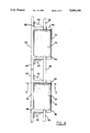
- FIG. 5 is a cross section view of a pair of stacked modules in the arrangement of FIG. 4, as viewed at 5--5.
- FIG. 6 is a rear perspective view of a portion of a module of another embodiment of the invention.
- FIG. 7 is a cross section view of the module of FIG. 6, as viewed at 7--7.
- retainer wall module 30 includes front wall 34 and a pair of buttress walls 40.
- Buttress walls 40 are the same height as front wall 34. They are reinforced in their attachment to the front wall by wings 44 and thickened portions 48. Preferably, the tops of buttress walls 40 and the top of front wall 34 are in the same plane.
- Horizontal base wall 52 is attached to buttress walls 40 and front wall 34.
- Upper recesses 58 and lower recesses 60 are provided to receive stabilizer bars 66 which will be described later.
- Lower recess 60 primarily extends upward into the buttress wall, but may also extend slightly into base wall 52 as shown in FIGS. 1 and 4.
- base wall 52, front wall 34 and wings 44 are preferably in the same plane, to provide maximum stability for the module on soft or yieldable earth.
- the lower surface area of wing 44 helps to resist forward rotation of the module in response to earth loading against the back of front wall 34.
- earth is used in the broadest sense. It includes such fill material, for example, as soil, rock, sand and gravel.
- Lock bar 72 in conjunction with retainer bar 74 shown in FIG. 3, locks geogrid 78 shown in FIG. 2, within the module when a portion of the geogrid is laid over bar 72, and under bar 74 which is positioned parallel to and against bar 72 on wall 52.
- the geogrid is wrapped around bar 74 before it is positioned in the module. Earth piled on the geogrid and bar assembly helps to tighten the lock.
- Geogrid fabric is commercially available from several sources.
- One source for example, is Mirafi brand Miragrid 5T, available from Mirafi Company, P.O. Box 240967, Charlotte, N.C. 28224, tel 800-438-1855.
- the geogrid fabric anchors in the earth by friction, and resists forces which cause rotation and displacement of the module.
- a pair of lock bars 72 which define a channel for receiving retainer bar 74 with wrapped geogrid.
- second tier modules 30 which are arranged adjacent to one another in part of a retaining wall, are stacked over another set of first tier modules that are not visible in this figure. Two of the stacked modules, however, are shown in cross section in FIG. 5.
- each module of the horizontal assembly of modules receives two stabilizer bars 66, one in each upper recess 58, which bridge between that module and its adjacent counterpart modules.
- stabilizer bar 66 also engages adjacent stacked modules to keep front walls 34 in the same plane and resist shear between the modules.
- the site for the wall is graded flat and level.
- the first tier of modules is placed on the graded land with the modules side by side, preferably with their front walls in the same plane.
- the geogrid is wrapped on retainer bar 74 which is installed within the module as described earlier.
- the geogrid is arrayed rearward on the graded surface, and land is backfilled over the graded surface to the height of front wall 34, and graded level.
- the graded surface over which the geogrid will be laid is brought up approximately to the level of lock bar 72 before the geogrid is arrayed rearward.
- the earth is channeled back between upper recesses 58 to allow stabilizer bars 66 between the modules to fully seat in the upper recesses.
- the second tier of modules is installed over the first tier, preferably with their front walls in the same plane as the walls below.
- the geogrid is installed within the second tier, and backfill and grading is undertaken as above.
- Module 30 is preferably molded from concrete, although it may be made from reinforced plastic or metal.
- the mold for the module includes metal facing for molding the top and bottom surfaces of the module, so that those surfaces are flat, smooth and parallel to one another.
- the present invention provides a modular retaining wall system that is anchored to the soil by weight of the soil and by friction with the soil for long time stability.
- the system includes a module which includes wings to resist rotation, geogrid fabric deployed to resist rotation and displacement of the module, and means for locking the geogrid fabric securely in the module.
- Stabilizer bars further resist rotation and relative shifting of assembled modules.
- the module is simply and easily installed without the need for footer or leveling pad.
Abstract
Description
Claims (15)
Priority Applications (1)
| Application Number | Priority Date | Filing Date | Title |
|---|---|---|---|
| US07/656,914 US5066169A (en) | 1991-02-19 | 1991-02-19 | Retaining wall system |
Applications Claiming Priority (1)
| Application Number | Priority Date | Filing Date | Title |
|---|---|---|---|
| US07/656,914 US5066169A (en) | 1991-02-19 | 1991-02-19 | Retaining wall system |
Publications (1)
| Publication Number | Publication Date |
|---|---|
| US5066169A true US5066169A (en) | 1991-11-19 |
Family
ID=24635085
Family Applications (1)
| Application Number | Title | Priority Date | Filing Date |
|---|---|---|---|
| US07/656,914 Expired - Lifetime US5066169A (en) | 1991-02-19 | 1991-02-19 | Retaining wall system |
Country Status (1)
| Country | Link |
|---|---|
| US (1) | US5066169A (en) |
Cited By (72)
| Publication number | Priority date | Publication date | Assignee | Title |
|---|---|---|---|---|
| US5214898A (en) * | 1990-08-20 | 1993-06-01 | Rdb Plastotecnica S.P.A. | Block particularly for building loose-laid retaining walls |
| US5257880A (en) * | 1990-07-26 | 1993-11-02 | Graystone Block Co. | Retaining wall construction and blocks therefor |
| US5277012A (en) * | 1992-07-22 | 1994-01-11 | Woolbright Mark A | Retaining wall building block |
| US5315802A (en) * | 1992-03-25 | 1994-05-31 | Solite Corporation | Modular wall system |
| DE4333942A1 (en) * | 1993-10-06 | 1995-04-13 | Sf Koop Gmbh Beton Konzepte | Construction set of shaped concrete blocks and device for producing the same |
| WO1995022663A1 (en) * | 1994-02-17 | 1995-08-24 | Earth Stabilizing Technology, Inc. | Earth-retaining module and system |
| US5484234A (en) * | 1994-09-30 | 1996-01-16 | Worden; Leonard A. | Building module for plantable walls with a bulk filling material |
| US5564865A (en) * | 1993-12-17 | 1996-10-15 | Jansson; Jan E. | Concrete module for retaining wall and improved retaining wall |
| US5568999A (en) * | 1995-04-03 | 1996-10-29 | The Tensar Corporation | Retaining wall block system |
| US5595460A (en) * | 1994-06-06 | 1997-01-21 | The Tensar Corporation | Modular block retaining wall system and method of constructing same |
| US5619835A (en) * | 1996-01-25 | 1997-04-15 | The Tensar Corporation | Modular block retaining wall system |
| US5658098A (en) * | 1995-07-26 | 1997-08-19 | Hercules Manufacturing, Inc. | Polymeric retaining wall building block |
| US5673530A (en) * | 1996-01-25 | 1997-10-07 | The Tensar Corporation | Modular block retaining wall system |
| WO1998006907A1 (en) * | 1996-08-09 | 1998-02-19 | Derrick Ian Peter Price | Soil reinforcement |
| US5788424A (en) * | 1996-05-01 | 1998-08-04 | Torch; Joe | Retaining wall units and retaining walls containing the same |
| US5836129A (en) * | 1993-09-01 | 1998-11-17 | Jaecklin; Felix Paul | Construction element, in particular supporting or sound insulating construction element capable of being planted, set of construction elements and process for producing the same |
| US5851088A (en) * | 1997-08-04 | 1998-12-22 | The Tensar Corporation | Modular retaining wall block system including wall blocks having replaceable dual purpose facing panels and removable spacing tabs |
| US5975809A (en) * | 1997-11-07 | 1999-11-02 | Taylor; Thomas P. | Apparatus and method for securing soil reinforcing elements to earthen retaining wall components |
| US6079908A (en) * | 1993-03-31 | 2000-06-27 | Societe Civile Des Brevets Henri Vidal | Stabilizing elements for mechanically stabilized earthen structure and mechanically stabilized earthen structure |
| USD435304S (en) * | 1998-03-19 | 2000-12-19 | Anchor Wall Systems, Inc. | Retaining wall block design |
| US6168351B1 (en) | 1997-04-30 | 2001-01-02 | Anchor Wall Systems, Inc. | Retaining wall anchoring system |
| US6213689B1 (en) * | 2000-04-12 | 2001-04-10 | Tokusuke Co., Ltd. | Construction unit for a retaining wall and a method for constructing the retaining wall |
| US6231272B1 (en) | 1999-12-14 | 2001-05-15 | Merrill E. Bishop | Construction block for making various structures |
| US6318934B1 (en) * | 1999-06-24 | 2001-11-20 | Anchor Wall Systems, Inc. | Segmental retaining wall system |
| US6338597B1 (en) * | 1998-03-27 | 2002-01-15 | Anchor Wall Systems, Inc. | Modular retaining wall system |
| US6416257B1 (en) | 1998-03-27 | 2002-07-09 | Anchor Wall Systems, Inc. | Segmental retaining wall system |
| US6505999B1 (en) | 2001-05-24 | 2003-01-14 | Huesker, Inc. | Retaining wall structure for soil stabilization including double layer of geogrid web material to provide high strength connection with backfill material |
| US6527865B1 (en) | 1997-09-11 | 2003-03-04 | Applied Materials, Inc. | Temperature controlled gas feedthrough |
| US20030070385A1 (en) * | 2001-10-11 | 2003-04-17 | Allan Block Corporation | Reinforcing system for stackable retaining wall units |
| US20030213203A1 (en) * | 2001-10-11 | 2003-11-20 | Allan Block Corporation | Reinforcing system for stackable retaining wall units |
| US6679656B1 (en) | 2002-12-13 | 2004-01-20 | Redi-Rock International, Llc | Connection for geogrid to concrete block earth retaining walls |
| WO2004011728A1 (en) | 2002-07-26 | 2004-02-05 | Jan Erik Jansson | Concrete module for retaining wall and improved retaining wall |
| US6692195B2 (en) * | 2001-10-25 | 2004-02-17 | Jan Erik Jansson | Plantable noise abatement wall |
| US6758636B2 (en) * | 1998-03-27 | 2004-07-06 | Anchor Wall Systems, Inc. | Segmental retaining wall system |
| US20040131429A1 (en) * | 1997-04-30 | 2004-07-08 | Rainey Thomas L. | Retaining wall anchoring system |
| US6862856B2 (en) | 2002-02-08 | 2005-03-08 | Anchor Wall Systems, Inc. | Corner block for use in forming a corner of a segmental retaining wall |
| US20050250348A1 (en) * | 2004-05-06 | 2005-11-10 | Applied Materials, Inc. | In-situ oxide capping after CVD low k deposition |
| US20060104725A1 (en) * | 2004-11-17 | 2006-05-18 | The Neel Company | Retaining wall construction element |
| US20060177278A1 (en) * | 2005-02-09 | 2006-08-10 | The Neel Company | Retaining wall construction element for railway installations |
| WO2006110943A1 (en) * | 2005-04-18 | 2006-10-26 | Rodney Henderson | Masonry block |
| US20060276054A1 (en) * | 2005-06-03 | 2006-12-07 | Applied Materials, Inc. | In situ oxide cap layer development |
| US20070009331A1 (en) * | 2004-10-19 | 2007-01-11 | Jeung Su Lee | Reinforcing strip for supporting reinforced earth wall and its placement method |
| US20080317557A1 (en) * | 2006-04-21 | 2008-12-25 | Felix Paul Jaecklin | Building Element For Making Walls Using Filling Material, Particularly Earth Or The Like |
| US7524144B2 (en) | 2004-06-22 | 2009-04-28 | Allan Block Corporation | Retaining wall |
| US20090148242A1 (en) * | 2007-12-10 | 2009-06-11 | Bruce Collet | Retaining wall system |
| US20090162147A1 (en) * | 2007-12-20 | 2009-06-25 | Earth Protection Systems, Inc. | Sand and soil internal reinforcement system |
| AU2006238320B2 (en) * | 2005-04-18 | 2010-06-24 | Henderson, Rodney Norman | Masonry block |
| US20100247248A1 (en) * | 2009-01-14 | 2010-09-30 | T & B Structural Systems Llc | Retaining wall soil reinforcing connector and method |
| US20100251649A1 (en) * | 2008-08-15 | 2010-10-07 | Smart Slope, Llc | Retaining Wall System |
| US20110135394A1 (en) * | 2009-12-08 | 2011-06-09 | Carlton Dudding | Berm and method of construction thereof |
| US20110170957A1 (en) * | 2010-01-08 | 2011-07-14 | T & B Structural Systems Llc | Wave anchor soil reinforcing connector and method |
| US20110170960A1 (en) * | 2010-01-08 | 2011-07-14 | T & B Structural Systems Llc | Splice for a soil reinforcing element or connector |
| US20110170958A1 (en) * | 2010-01-08 | 2011-07-14 | T & B Structural Systems Llc | Soil reinforcing connector and method of constructing a mechanically stabilized earth structure |
| US20110182673A1 (en) * | 2008-06-04 | 2011-07-28 | T & B Structural Systems Llc | Two stage mechanically stabilized earth wall system |
| US20110229274A1 (en) * | 2009-01-14 | 2011-09-22 | T & B Structural Systems Llc | Retaining wall soil reinforcing connector and method |
| US20120237299A1 (en) * | 2009-12-08 | 2012-09-20 | Carlton Dudding | Berm and method of construction thereof |
| US8632280B2 (en) | 2010-06-17 | 2014-01-21 | T & B Structural Systems Llc | Mechanically stabilized earth welded wire facing connection system and method |
| US8632282B2 (en) | 2010-06-17 | 2014-01-21 | T & B Structural Systems Llc | Mechanically stabilized earth system and method |
| US8632281B2 (en) | 2010-06-17 | 2014-01-21 | T & B Structural Systems Llc | Mechanically stabilized earth system and method |
| US8632278B2 (en) | 2010-06-17 | 2014-01-21 | T & B Structural Systems Llc | Mechanically stabilized earth welded wire facing connection system and method |
| US8734059B2 (en) | 2010-06-17 | 2014-05-27 | T&B Structural Systems Llc | Soil reinforcing element for a mechanically stabilized earth structure |
| US20140270990A1 (en) * | 2013-03-15 | 2014-09-18 | Utility Concrete Products, Llc | Precast concrete retaining wall |
| US8961073B2 (en) | 2009-12-08 | 2015-02-24 | Awt Ip, Llc | System and method for strengthening a sloped structure such as a berm, basin, levee, embankment, or the like |
| US9662692B2 (en) | 2009-12-08 | 2017-05-30 | Awt Ip, Llc | Landfill and berm combination |
| US9663907B2 (en) * | 2012-06-28 | 2017-05-30 | Earth Wall Products, Llc | Precast traffic barrier atop retaining wall system |
| USD805206S1 (en) * | 2014-12-15 | 2017-12-12 | Hailey Hill | Arm support |
| US10145079B1 (en) | 2017-10-31 | 2018-12-04 | Awt Ip Llc | Berm and method of manufacturing a berm |
| US10273648B2 (en) * | 2016-03-02 | 2019-04-30 | Evergreen Walls, Inc. | Building elements for making retaining walls, and systems and methods of using same |
| US10676890B2 (en) | 2016-03-30 | 2020-06-09 | Robert Gordon McIntosh | Retaining wall system, method of supporting same, and kit for use in constructing same |
| USD895153S1 (en) | 2018-10-05 | 2020-09-01 | Pacific Prebenched Ltd. | Block for a retaining wall |
| US10895055B1 (en) * | 2013-02-08 | 2021-01-19 | Mortarless Technologies Llc | Molded concrete blocks having simulated brick or stone outer surfaces |
| US11149402B2 (en) | 2016-03-02 | 2021-10-19 | Evergreen Walls, Inc. | Building elements for making retaining walls, and systems and methods of using same |
Citations (10)
| Publication number | Priority date | Publication date | Assignee | Title |
|---|---|---|---|---|
| US770844A (en) * | 1904-07-29 | 1904-09-27 | William L Church | Retaining-wall. |
| US1349166A (en) * | 1918-05-25 | 1920-08-10 | Paff Charles | Retaining-wall for embankments |
| US1663453A (en) * | 1925-09-10 | 1928-03-20 | Coke-Hill Lionel | Quay wall |
| US4521138A (en) * | 1980-09-05 | 1985-06-04 | Steiner Silidur Ag | Building blocks |
| US4661023A (en) * | 1985-12-30 | 1987-04-28 | Hilfiker Pipe Co. | Riveted plate connector for retaining wall face panels |
| US4668129A (en) * | 1985-09-06 | 1987-05-26 | Stresswall International Incorporated | Retaining wall system using soil arching |
| US4671706A (en) * | 1985-10-17 | 1987-06-09 | Arnaldo Giardini | Concrete retaining wall block |
| US4684294A (en) * | 1986-01-15 | 1987-08-04 | Neill Raymond J O | Retaining wall construction element |
| US4804299A (en) * | 1986-07-09 | 1989-02-14 | United International, Inc. | Retaining wall system |
| US4884921A (en) * | 1988-09-15 | 1989-12-05 | Fomico International, Inc. | Retaining wall module having face panel and T-stem with means for receiving transverse stabilizing web |
-
1991
- 1991-02-19 US US07/656,914 patent/US5066169A/en not_active Expired - Lifetime
Patent Citations (10)
| Publication number | Priority date | Publication date | Assignee | Title |
|---|---|---|---|---|
| US770844A (en) * | 1904-07-29 | 1904-09-27 | William L Church | Retaining-wall. |
| US1349166A (en) * | 1918-05-25 | 1920-08-10 | Paff Charles | Retaining-wall for embankments |
| US1663453A (en) * | 1925-09-10 | 1928-03-20 | Coke-Hill Lionel | Quay wall |
| US4521138A (en) * | 1980-09-05 | 1985-06-04 | Steiner Silidur Ag | Building blocks |
| US4668129A (en) * | 1985-09-06 | 1987-05-26 | Stresswall International Incorporated | Retaining wall system using soil arching |
| US4671706A (en) * | 1985-10-17 | 1987-06-09 | Arnaldo Giardini | Concrete retaining wall block |
| US4661023A (en) * | 1985-12-30 | 1987-04-28 | Hilfiker Pipe Co. | Riveted plate connector for retaining wall face panels |
| US4684294A (en) * | 1986-01-15 | 1987-08-04 | Neill Raymond J O | Retaining wall construction element |
| US4804299A (en) * | 1986-07-09 | 1989-02-14 | United International, Inc. | Retaining wall system |
| US4884921A (en) * | 1988-09-15 | 1989-12-05 | Fomico International, Inc. | Retaining wall module having face panel and T-stem with means for receiving transverse stabilizing web |
Cited By (107)
| Publication number | Priority date | Publication date | Assignee | Title |
|---|---|---|---|---|
| US5257880A (en) * | 1990-07-26 | 1993-11-02 | Graystone Block Co. | Retaining wall construction and blocks therefor |
| US5214898A (en) * | 1990-08-20 | 1993-06-01 | Rdb Plastotecnica S.P.A. | Block particularly for building loose-laid retaining walls |
| US5315802A (en) * | 1992-03-25 | 1994-05-31 | Solite Corporation | Modular wall system |
| US5277012A (en) * | 1992-07-22 | 1994-01-11 | Woolbright Mark A | Retaining wall building block |
| US6079908A (en) * | 1993-03-31 | 2000-06-27 | Societe Civile Des Brevets Henri Vidal | Stabilizing elements for mechanically stabilized earthen structure and mechanically stabilized earthen structure |
| US5836129A (en) * | 1993-09-01 | 1998-11-17 | Jaecklin; Felix Paul | Construction element, in particular supporting or sound insulating construction element capable of being planted, set of construction elements and process for producing the same |
| DE4333942A1 (en) * | 1993-10-06 | 1995-04-13 | Sf Koop Gmbh Beton Konzepte | Construction set of shaped concrete blocks and device for producing the same |
| US5564865A (en) * | 1993-12-17 | 1996-10-15 | Jansson; Jan E. | Concrete module for retaining wall and improved retaining wall |
| WO1995022663A1 (en) * | 1994-02-17 | 1995-08-24 | Earth Stabilizing Technology, Inc. | Earth-retaining module and system |
| US5499891A (en) * | 1994-02-17 | 1996-03-19 | Earth Stabilizing Technology, Inc. | Earth-retaining module and system |
| US5595460A (en) * | 1994-06-06 | 1997-01-21 | The Tensar Corporation | Modular block retaining wall system and method of constructing same |
| US5484234A (en) * | 1994-09-30 | 1996-01-16 | Worden; Leonard A. | Building module for plantable walls with a bulk filling material |
| US5568999A (en) * | 1995-04-03 | 1996-10-29 | The Tensar Corporation | Retaining wall block system |
| US5658098A (en) * | 1995-07-26 | 1997-08-19 | Hercules Manufacturing, Inc. | Polymeric retaining wall building block |
| US5673530A (en) * | 1996-01-25 | 1997-10-07 | The Tensar Corporation | Modular block retaining wall system |
| US5619835A (en) * | 1996-01-25 | 1997-04-15 | The Tensar Corporation | Modular block retaining wall system |
| US5788424A (en) * | 1996-05-01 | 1998-08-04 | Torch; Joe | Retaining wall units and retaining walls containing the same |
| WO1998006907A1 (en) * | 1996-08-09 | 1998-02-19 | Derrick Ian Peter Price | Soil reinforcement |
| US6224295B1 (en) | 1996-08-09 | 2001-05-01 | Derrick Ian Peter Price | Soil reinforcement |
| US6168351B1 (en) | 1997-04-30 | 2001-01-02 | Anchor Wall Systems, Inc. | Retaining wall anchoring system |
| US6935812B2 (en) | 1997-04-30 | 2005-08-30 | Anchor Wall Systems, Inc. | Retaining wall anchoring system |
| US20040131429A1 (en) * | 1997-04-30 | 2004-07-08 | Rainey Thomas L. | Retaining wall anchoring system |
| US5851088A (en) * | 1997-08-04 | 1998-12-22 | The Tensar Corporation | Modular retaining wall block system including wall blocks having replaceable dual purpose facing panels and removable spacing tabs |
| US6527865B1 (en) | 1997-09-11 | 2003-03-04 | Applied Materials, Inc. | Temperature controlled gas feedthrough |
| US5975809A (en) * | 1997-11-07 | 1999-11-02 | Taylor; Thomas P. | Apparatus and method for securing soil reinforcing elements to earthen retaining wall components |
| USD435304S (en) * | 1998-03-19 | 2000-12-19 | Anchor Wall Systems, Inc. | Retaining wall block design |
| US6416257B1 (en) | 1998-03-27 | 2002-07-09 | Anchor Wall Systems, Inc. | Segmental retaining wall system |
| US6921231B2 (en) | 1998-03-27 | 2005-07-26 | Anchor Wall Systems, Inc. | Segmental retaining wall system |
| US20040179903A1 (en) * | 1998-03-27 | 2004-09-16 | Anchor Wall Systems, Inc. | Segmental retaining wall system |
| US6338597B1 (en) * | 1998-03-27 | 2002-01-15 | Anchor Wall Systems, Inc. | Modular retaining wall system |
| US6758636B2 (en) * | 1998-03-27 | 2004-07-06 | Anchor Wall Systems, Inc. | Segmental retaining wall system |
| USRE39922E1 (en) | 1999-06-24 | 2007-11-20 | Anchor Wall Systems, Inc. | Segmental retaining wall system |
| US6318934B1 (en) * | 1999-06-24 | 2001-11-20 | Anchor Wall Systems, Inc. | Segmental retaining wall system |
| US6231272B1 (en) | 1999-12-14 | 2001-05-15 | Merrill E. Bishop | Construction block for making various structures |
| US6213689B1 (en) * | 2000-04-12 | 2001-04-10 | Tokusuke Co., Ltd. | Construction unit for a retaining wall and a method for constructing the retaining wall |
| US6505999B1 (en) | 2001-05-24 | 2003-01-14 | Huesker, Inc. | Retaining wall structure for soil stabilization including double layer of geogrid web material to provide high strength connection with backfill material |
| US6854236B2 (en) | 2001-10-11 | 2005-02-15 | Allan Block Corporation | Reinforcing system for stackable retaining wall units |
| US20030213203A1 (en) * | 2001-10-11 | 2003-11-20 | Allan Block Corporation | Reinforcing system for stackable retaining wall units |
| US20030070385A1 (en) * | 2001-10-11 | 2003-04-17 | Allan Block Corporation | Reinforcing system for stackable retaining wall units |
| US6792731B2 (en) | 2001-10-11 | 2004-09-21 | Timothy A. Bott | Reinforcing system for stackable retaining wall units |
| US6692195B2 (en) * | 2001-10-25 | 2004-02-17 | Jan Erik Jansson | Plantable noise abatement wall |
| US6862856B2 (en) | 2002-02-08 | 2005-03-08 | Anchor Wall Systems, Inc. | Corner block for use in forming a corner of a segmental retaining wall |
| WO2004011728A1 (en) | 2002-07-26 | 2004-02-05 | Jan Erik Jansson | Concrete module for retaining wall and improved retaining wall |
| US6761509B2 (en) | 2002-07-26 | 2004-07-13 | Jan Erik Jansson | Concrete module for retaining wall and improved retaining wall |
| WO2004018779A3 (en) * | 2002-08-21 | 2004-05-13 | Block Allan Corp | Reinforcing system for stackable retaining wall units |
| WO2004018779A2 (en) * | 2002-08-21 | 2004-03-04 | Allan Block Corporation | Reinforcing system for stackable retaining wall units |
| US6679656B1 (en) | 2002-12-13 | 2004-01-20 | Redi-Rock International, Llc | Connection for geogrid to concrete block earth retaining walls |
| US20050250348A1 (en) * | 2004-05-06 | 2005-11-10 | Applied Materials, Inc. | In-situ oxide capping after CVD low k deposition |
| US7112541B2 (en) | 2004-05-06 | 2006-09-26 | Applied Materials, Inc. | In-situ oxide capping after CVD low k deposition |
| US7524144B2 (en) | 2004-06-22 | 2009-04-28 | Allan Block Corporation | Retaining wall |
| US20070009331A1 (en) * | 2004-10-19 | 2007-01-11 | Jeung Su Lee | Reinforcing strip for supporting reinforced earth wall and its placement method |
| US20060104725A1 (en) * | 2004-11-17 | 2006-05-18 | The Neel Company | Retaining wall construction element |
| US20060177278A1 (en) * | 2005-02-09 | 2006-08-10 | The Neel Company | Retaining wall construction element for railway installations |
| US7090439B1 (en) * | 2005-02-09 | 2006-08-15 | The Neel Company | Retaining wall construction element for railway installations |
| WO2006110943A1 (en) * | 2005-04-18 | 2006-10-26 | Rodney Henderson | Masonry block |
| GB2439506A (en) * | 2005-04-18 | 2007-12-27 | Rodney Henderson | Masonry block |
| US20080134603A1 (en) * | 2005-04-18 | 2008-06-12 | Rodney Henderson | Masonry Block |
| US7517176B2 (en) | 2005-04-18 | 2009-04-14 | Rodney Henderson | Masonry block |
| AU2006238320B2 (en) * | 2005-04-18 | 2010-06-24 | Henderson, Rodney Norman | Masonry block |
| US20060276054A1 (en) * | 2005-06-03 | 2006-12-07 | Applied Materials, Inc. | In situ oxide cap layer development |
| US7273823B2 (en) | 2005-06-03 | 2007-09-25 | Applied Materials, Inc. | Situ oxide cap layer development |
| US7845885B2 (en) | 2006-04-21 | 2010-12-07 | Felix Paul Jaecklin | Building element for making walls using filling material, particularly earth or the like |
| US20080317557A1 (en) * | 2006-04-21 | 2008-12-25 | Felix Paul Jaecklin | Building Element For Making Walls Using Filling Material, Particularly Earth Or The Like |
| US20090148242A1 (en) * | 2007-12-10 | 2009-06-11 | Bruce Collet | Retaining wall system |
| US20090162147A1 (en) * | 2007-12-20 | 2009-06-25 | Earth Protection Systems, Inc. | Sand and soil internal reinforcement system |
| US20110182673A1 (en) * | 2008-06-04 | 2011-07-28 | T & B Structural Systems Llc | Two stage mechanically stabilized earth wall system |
| US8496411B2 (en) | 2008-06-04 | 2013-07-30 | T & B Structural Systems Llc | Two stage mechanically stabilized earth wall system |
| US8272812B2 (en) * | 2008-08-15 | 2012-09-25 | Smart Slope Llc | Retaining wall system |
| US8745953B2 (en) | 2008-08-15 | 2014-06-10 | Smart Slope, Llc | Retaining wall system |
| US20100251649A1 (en) * | 2008-08-15 | 2010-10-07 | Smart Slope, Llc | Retaining Wall System |
| US9605402B2 (en) | 2009-01-14 | 2017-03-28 | Thomas P. Taylor | Retaining wall soil reinforcing connector and method |
| US20100247248A1 (en) * | 2009-01-14 | 2010-09-30 | T & B Structural Systems Llc | Retaining wall soil reinforcing connector and method |
| US8632277B2 (en) | 2009-01-14 | 2014-01-21 | T & B Structural Systems Llc | Retaining wall soil reinforcing connector and method |
| US20110229274A1 (en) * | 2009-01-14 | 2011-09-22 | T & B Structural Systems Llc | Retaining wall soil reinforcing connector and method |
| US9540784B2 (en) | 2009-12-08 | 2017-01-10 | Awt Ip Llc | Berm and method of construction thereof |
| US9649673B2 (en) | 2009-12-08 | 2017-05-16 | Awt Ip Llc | System and method for strengthening a sloped structure such as a berm, basin, levee, embankment, or the like |
| US20120237299A1 (en) * | 2009-12-08 | 2012-09-20 | Carlton Dudding | Berm and method of construction thereof |
| US8961073B2 (en) | 2009-12-08 | 2015-02-24 | Awt Ip, Llc | System and method for strengthening a sloped structure such as a berm, basin, levee, embankment, or the like |
| US10174477B2 (en) | 2009-12-08 | 2019-01-08 | Awt Ip Llc | Reinforced wall system |
| US9662692B2 (en) | 2009-12-08 | 2017-05-30 | Awt Ip, Llc | Landfill and berm combination |
| US8845240B2 (en) * | 2009-12-08 | 2014-09-30 | Awt Ip, Llc | Berm and method of construction thereof |
| US9593459B2 (en) | 2009-12-08 | 2017-03-14 | Awt Ip Llc | System and method for strengthening a sloped structure |
| US8784008B2 (en) | 2009-12-08 | 2014-07-22 | Awt Ip, Llc | Berm and method of construction thereof |
| US20110135394A1 (en) * | 2009-12-08 | 2011-06-09 | Carlton Dudding | Berm and method of construction thereof |
| US20110170957A1 (en) * | 2010-01-08 | 2011-07-14 | T & B Structural Systems Llc | Wave anchor soil reinforcing connector and method |
| US8632279B2 (en) | 2010-01-08 | 2014-01-21 | T & B Structural Systems Llc | Splice for a soil reinforcing element or connector |
| US8393829B2 (en) | 2010-01-08 | 2013-03-12 | T&B Structural Systems Llc | Wave anchor soil reinforcing connector and method |
| US20110170960A1 (en) * | 2010-01-08 | 2011-07-14 | T & B Structural Systems Llc | Splice for a soil reinforcing element or connector |
| US20110170958A1 (en) * | 2010-01-08 | 2011-07-14 | T & B Structural Systems Llc | Soil reinforcing connector and method of constructing a mechanically stabilized earth structure |
| US8632281B2 (en) | 2010-06-17 | 2014-01-21 | T & B Structural Systems Llc | Mechanically stabilized earth system and method |
| US8632280B2 (en) | 2010-06-17 | 2014-01-21 | T & B Structural Systems Llc | Mechanically stabilized earth welded wire facing connection system and method |
| US8734059B2 (en) | 2010-06-17 | 2014-05-27 | T&B Structural Systems Llc | Soil reinforcing element for a mechanically stabilized earth structure |
| US8632278B2 (en) | 2010-06-17 | 2014-01-21 | T & B Structural Systems Llc | Mechanically stabilized earth welded wire facing connection system and method |
| US8632282B2 (en) | 2010-06-17 | 2014-01-21 | T & B Structural Systems Llc | Mechanically stabilized earth system and method |
| US9663907B2 (en) * | 2012-06-28 | 2017-05-30 | Earth Wall Products, Llc | Precast traffic barrier atop retaining wall system |
| US10895055B1 (en) * | 2013-02-08 | 2021-01-19 | Mortarless Technologies Llc | Molded concrete blocks having simulated brick or stone outer surfaces |
| US11053656B1 (en) | 2013-02-08 | 2021-07-06 | Mortarless Technologies Llc | Method of making molded concrete blocks having simulated brick or stone outer surfaces |
| US20140270990A1 (en) * | 2013-03-15 | 2014-09-18 | Utility Concrete Products, Llc | Precast concrete retaining wall |
| USD805206S1 (en) * | 2014-12-15 | 2017-12-12 | Hailey Hill | Arm support |
| US10273648B2 (en) * | 2016-03-02 | 2019-04-30 | Evergreen Walls, Inc. | Building elements for making retaining walls, and systems and methods of using same |
| US20190368151A1 (en) * | 2016-03-02 | 2019-12-05 | Evergreen Walls, Inc. | Building elements for making retaining walls, and systems and methods of using same |
| US11149402B2 (en) | 2016-03-02 | 2021-10-19 | Evergreen Walls, Inc. | Building elements for making retaining walls, and systems and methods of using same |
| US20220081868A1 (en) * | 2016-03-02 | 2022-03-17 | Evergreen Walls, Inc. | Building Elements For Making Retaining Walls, And Systems And Methods Of Using Same |
| US11661719B2 (en) * | 2016-03-02 | 2023-05-30 | Evergreen Walls, Inc. | Building elements for making retaining walls, and systems and methods of using same |
| US10676890B2 (en) | 2016-03-30 | 2020-06-09 | Robert Gordon McIntosh | Retaining wall system, method of supporting same, and kit for use in constructing same |
| US10145079B1 (en) | 2017-10-31 | 2018-12-04 | Awt Ip Llc | Berm and method of manufacturing a berm |
| USD895153S1 (en) | 2018-10-05 | 2020-09-01 | Pacific Prebenched Ltd. | Block for a retaining wall |
Similar Documents
| Publication | Publication Date | Title |
|---|---|---|
| US5066169A (en) | Retaining wall system | |
| US5131791A (en) | Retaining wall system | |
| EP0067551B1 (en) | Reinforced earth structures and facing units therefor | |
| US5702208A (en) | Grid-locked block panel system | |
| US4884921A (en) | Retaining wall module having face panel and T-stem with means for receiving transverse stabilizing web | |
| US4804299A (en) | Retaining wall system | |
| US6615561B2 (en) | Retaining wall block | |
| US5494379A (en) | Earthen work with wire mesh facing | |
| JP3817676B2 (en) | Module block retaining wall structure and components | |
| AU759658B2 (en) | Retaining wall system | |
| CA1043581A (en) | Quay structure | |
| US5419092A (en) | Structures and process for producing same, as well as associated elements and sets of construction elements | |
| US4728225A (en) | Method of rehabilitating a waterfront bulkhead | |
| US4990032A (en) | Retaining wall module with asymmetrical anchor | |
| US20030140585A1 (en) | Retaining wall system | |
| US20090196695A1 (en) | Modular Block Connecting Techniques | |
| US5577866A (en) | Earthen work with wire mesh facing | |
| US4923339A (en) | Foldable concrete retaining wall structure | |
| EP0617750A1 (en) | Interlocked gridwork for retaining walls, and the like | |
| US5030035A (en) | Earth retaining system | |
| US6113316A (en) | Retaining wall system | |
| US5356242A (en) | System and method for adjustably connecting wall facing panels to the soldier beams of a tie-back or anchored wall | |
| US4936713A (en) | Earth retaining system | |
| US2880588A (en) | Retaining walls | |
| US5123777A (en) | Construction elements |
Legal Events
| Date | Code | Title | Description |
|---|---|---|---|
| STCF | Information on status: patent grant |
Free format text: PATENTED CASE |
|
| FPAY | Fee payment |
Year of fee payment: 4 |
|
| REMI | Maintenance fee reminder mailed | ||
| FPAY | Fee payment |
Year of fee payment: 8 |
|
| SULP | Surcharge for late payment | ||
| FPAY | Fee payment |
Year of fee payment: 12 |
|
| AS | Assignment |
Owner name: THE PETER GAVIN SPRAY TRUST UNDER AGREEMENT DATED Free format text: ASSIGNMENT OF ASSIGNORS INTEREST;ASSIGNOR:GAVIN, NORMAN W.;REEL/FRAME:015503/0469 Effective date: 20041115 |
|
| AS | Assignment |
Owner name: WEBSTER BANK, NATIONAL ASSOCIATION, CONNECTICUT Free format text: SECURITY AGREEMENT;ASSIGNOR:THE PETER W. GAVIN SPRAY TRUST;REEL/FRAME:017480/0502 Effective date: 20060314 |
|
| AS | Assignment |
Owner name: WEBSTER BANK, NATIONAL ASSOCIATION, CONNECTICUT Free format text: RELEASE;ASSIGNORS:PETER W. GAVIN SPRAY TRUST DATED MAY 26,2004, THE;GAVIN, PETER W.;REEL/FRAME:028620/0336 Effective date: 20120627 |