US5068847A - Fiber optic network architecture having data feedback for monitoring communications thereon - Google Patents
Fiber optic network architecture having data feedback for monitoring communications thereon Download PDFInfo
- Publication number
- US5068847A US5068847A US07/423,906 US42390689A US5068847A US 5068847 A US5068847 A US 5068847A US 42390689 A US42390689 A US 42390689A US 5068847 A US5068847 A US 5068847A
- Authority
- US
- United States
- Prior art keywords
- optical
- bus
- coupler
- terminal
- controller
- Prior art date
- Legal status (The legal status is an assumption and is not a legal conclusion. Google has not performed a legal analysis and makes no representation as to the accuracy of the status listed.)
- Expired - Lifetime
Links
Images


Classifications
-
- H—ELECTRICITY
- H04—ELECTRIC COMMUNICATION TECHNIQUE
- H04J—MULTIPLEX COMMUNICATION
- H04J14/00—Optical multiplex systems
-
- H—ELECTRICITY
- H04—ELECTRIC COMMUNICATION TECHNIQUE
- H04B—TRANSMISSION
- H04B10/00—Transmission systems employing electromagnetic waves other than radio-waves, e.g. infrared, visible or ultraviolet light, or employing corpuscular radiation, e.g. quantum communication
- H04B10/07—Arrangements for monitoring or testing transmission systems; Arrangements for fault measurement of transmission systems
- H04B10/075—Arrangements for monitoring or testing transmission systems; Arrangements for fault measurement of transmission systems using an in-service signal
- H04B10/079—Arrangements for monitoring or testing transmission systems; Arrangements for fault measurement of transmission systems using an in-service signal using measurements of the data signal
- H04B10/0795—Performance monitoring; Measurement of transmission parameters
- H04B10/07953—Monitoring or measuring OSNR, BER or Q
Definitions
- This invention relates to data transmission networks, and more particularly, to a fiber optic network having data feedback.
- every terminal is capable of hearing the information or data transmission of any other terminal in the network to determine when the bus is idle.
- the architecture inherently provides signal feedback so that each terminal hears its own transmissions.
- the architecture provides a wrap-around of data output on the bus back to the transmitting terminal's receiver (i.e., star, linear bus . . . )
- no additional feedback apparatus is necessary to monitor the integrity of the data outputted onto the bus.
- the present invention finds particular application in a non-autonomous fiber optic data network, and may be applied directly to aircraft flight controls.
- Optical data transfer is a relatively new technology that is replacing copper wire data buses in some application areas.
- a simple tee connection can be utilized in a copper wire data bus to provide feedback of the data output from a terminal connected to the data bus. This is not physically possible in a fiber optic network because of the directional nature of light.
- System wrap-around techniques have been utilized to monitor the integrity of data on an optical bus. With this technique, data output from a controlling terminal is received by slave terminals and decoded. A message indicating the integrity of the received signal is then transmitted back to the master terminal by at least one slave terminal.
- the system wrap-around technique results in relatively high system complexity in that many active components are required to implement this monitoring technique.
- the system wrap-around technique results in high bandwidth requirements on the fiber optic bus because information regarding the integrity of the received signal must be transmitted from one or more slave terminals back to the controller.
- the present invention provides a fundamentally different scheme for monitoring the data on the optical bus then heretofore mentioned.
- the present invention uses passive optical couplers to tap off a percentage of the optical power, which is routed to the terminal's receiver.
- This implementation therefore, requires no active components outside of the enclosure of the terminal to monitor the data bus.
- the bus in the present invention is being monitored at the terminal's output rather than at the opposite end of the data bus, thus providing very reliable information of the data being output onto the bus by the terminal being monitored.
- Increased bandwidth requirements are not imposed on the bus to implement the monitoring technique because the slave terminals are not required to transmit back any information for the monitoring technique of the present invention to be realized.
- a communication network which includes an apparatus for communicating on a fiber optic bus of a fiber optic data network, the apparatus including monitoring the integrity of data outputted onto the bus.
- a non-autonomous fiber optic network having the capability of monitoring data communications of said fiber optic network comprises an optical fiber cable which provides an optical medium (i.e., bus) for communicating optical signals.
- a bus controller controls the communications of optical information on the optical fiber cable. The bus controller also monitors the optical information outputted on the optical fiber cable, thereby verifying the integrity of the optical information transmitted to terminals connected to the optical fiber cable.
- An optical interface of the bus controller taps a percentage of power that is outputted onto the optical fiber bus and routes that signal to a receiver unit of the bus controller. That signal is utilized by the bus controller to monitor the integrity of the transmitted data that is outputted on the optical fiber bus.
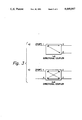
- FIG. 1 shows a schematic drawing of a dual-tree architecture of a fiber optic network of the preferred embodiment of the present invention
- FIG. 2 shows a functional block diagram of an optical interface unit utilized in the fiber optic network of FIG. 1;
- FIG. 3 shows a functional block drawing of the directional couplers utilized in the preferred embodiment of the present invention.
- the fiber optic network 10 includes a first fiber optic cable 11 and a second fiber optic cable 11' each cable forming a bidirectional fiber optic data bus.
- a centralized bus controller (or bus master) 12 is connected to both the first and second fiber optic cable 11, 11', via an input/output unit, I/01 and I/02, 14 and 14' respectively, the bus controller 12 also including controller logic 15.
- the bus controller 12 is a master terminal connected to the fiber optic cables 11, 11' which communicates (receives and transmits) to other terminals (T) 13 connected to the extension of the fiber optic cables 11, 11' described below, the terminals (T) 13 being slave terminals.
- the fiber optic cables 11, 11' are connected to a corresponding coupler 16, 16'.
- Each terminal 13 receives or transmits to the bus controller 12.
- I/O units 14, 14' comprise the optical interface of the bus controller 12.
- the controller logic 15 of the bus controller 12 performs the control function according to a predetermined protocol well known to those skilled in the art and will not be discussed further herein since it is not necessary for an understanding of the present invention.
- FIG. 2 there is shown a functional block diagram of the I/O unit 14 and an optical interface 30 of terminal 13.
- Each I/O unit 14, 14' forms the optical interface between the electrical signals of controller logic 15 and the optical signals of the fiber optic cable 11, 11', respectively.
- Electrical signals from the logic 15 of bus controller 12 are inputted to an electrical-to-optical converter (transmitter) 21, the output of transmitter 21 being an optical power signal which is coupled by a fiber 28 to port 4 of transmitter coupler (Y-coupler) 22.
- Y-coupler 22 is a 1 ⁇ 2 directional coupler.
- Directional couplers currently available deliver nearly 100% of the power from port 4 of the Y-coupler 22 to ports 2 and 3 (of the Y-coupler 22), and have split ratios of power output (i.e., the ratio of power output to port 2 compared with the power output to port 3).
- the split ratio for the Y-coupler 22 of the preferred embodiment of the present invention is chosen such that the power loss from the transmitter 21 to an optical-to-electrical converter (receiver) 23 via a wrap-around loop 25 is approximately equal to the loss from transmitter 21 to an optical-to-electrical converter 33 of the optical interface 30 of the terminal 13.
- Power outputted to port 3 of Y-coupler 22 is coupled to port 1 of receiver coupler (R-coupler) 24, in the preferred embodiment the R-coupler 24 being a 2 ⁇ 2 directional coupler.
- Power which is outputted from port 2 of Y-coupler 22 is coupled via the wrap-around loop 25 to port 2 of R-coupler 24.
- Fifty percent (50%) of the power inputted to port 1 of R-coupler 24 is outputted to port 3 of R-coupler 24 and launched onto the bidirectional fiber optic bus 11.
- Fifty percent (50%) of the power inputted to port 2 of R-coupler 24 is outputted at port 4 of R-coupler 4. (There is some loss of about 1 db in the coupler which has not been considered in order to emphasize the description of the operation of the apparatus.)
- the power outputted at port 4 of the R-coupler 24 is coupled, via fiber optic cable 29, to the receiver 23, thereby permitting the bus controller 12 to monitor the data outputted by its transmitter 21.
- the power outputted from the transmitter 21 which is not coupled to the cable 11, or to the receiver 23 is not used and does not interfere or enhance the performance of the network 10.
- the preferred embodiment of the present invention utilizes standard, commercially available directional couplers, and can be implemented in single mode or multimode systems.
- only a 1 to 3 db additional loss was experienced in providing the monitoring capability of the present invention, the exact loss being dependent on the splitting ratio of the Y-coupler 22.
- FIG. 3 there is shown a functional block drawing of the directional couplers utilized in the preferred embodiment of the present invention, indicating transmission paths and directions of the transmissions between ports.
- Optic power input at port 1 of the 2 ⁇ 2 directional coupler is output to ports 2 and 3.
- the splitting ratio is the power output to port 2 divided by that which is output to port 3.
- the same splitting ratio is observed at output ports 1 and 4 as exists between ports 2 and 3 with input at port 1.
- the port directly across from the input port is the favored port, receiving at least 50% of the input power.
- the other output port is the tap port.
- This observation demonstrates the symmetrical nature of directional couplers. Couplers also demonstrate the property of reciprocity, i.e., the loss between any two ports is independent of the direction of travel of the optic power signal.
- the loss from port 1 to port 3 is the same as the loss from port 3 to 1.
- a dual tree network is not necessary to implement the present invention, and likewise, the tree architecture can be expanded to include triple, quadruple , . . . tree architectures within the spirit of the present invention.
- the 1 ⁇ 3 star couplers utilized in the present invention are commercially available, the coupler used in the preferred embodiment of the present invention is Kaptron C88-7019-26-1. Further, the 1 ⁇ 2 directional coupler and the 2 ⁇ 2 directional coupler used in the preferred embodiment of the present invention are also commercially available.
Abstract
Description
Claims (2)
Priority Applications (1)
| Application Number | Priority Date | Filing Date | Title |
|---|---|---|---|
| US07/423,906 US5068847A (en) | 1989-10-19 | 1989-10-19 | Fiber optic network architecture having data feedback for monitoring communications thereon |
Applications Claiming Priority (1)
| Application Number | Priority Date | Filing Date | Title |
|---|---|---|---|
| US07/423,906 US5068847A (en) | 1989-10-19 | 1989-10-19 | Fiber optic network architecture having data feedback for monitoring communications thereon |
Publications (1)
| Publication Number | Publication Date |
|---|---|
| US5068847A true US5068847A (en) | 1991-11-26 |
Family
ID=23680646
Family Applications (1)
| Application Number | Title | Priority Date | Filing Date |
|---|---|---|---|
| US07/423,906 Expired - Lifetime US5068847A (en) | 1989-10-19 | 1989-10-19 | Fiber optic network architecture having data feedback for monitoring communications thereon |
Country Status (1)
| Country | Link |
|---|---|
| US (1) | US5068847A (en) |
Cited By (4)
| Publication number | Priority date | Publication date | Assignee | Title |
|---|---|---|---|---|
| US5680546A (en) * | 1991-12-20 | 1997-10-21 | Italtel Societa Italiana Telecomunicazioni, S.P.A. | Passive optical network structure with high fault tolerance |
| US20110200336A1 (en) * | 2007-11-08 | 2011-08-18 | Airbus Operations (S.A.S.) | Avionics equipment with optical contact and avionics system comprising such equipment |
| US10263706B2 (en) * | 2017-04-18 | 2019-04-16 | The Boeing Company | Single-fiber bidirectional controller area network bus |
| EP4280552A1 (en) * | 2022-05-17 | 2023-11-22 | Phoenix Contact Gmbh & Co. Kg | Primary communication device, coupling module and communication system |
Citations (3)
| Publication number | Priority date | Publication date | Assignee | Title |
|---|---|---|---|---|
| JPS594341A (en) * | 1982-06-30 | 1984-01-11 | Fujitsu Ltd | Method for monitoring failure |
| SU1145487A1 (en) * | 1983-04-20 | 1985-03-15 | Московский Ордена Трудового Красного Знамени Электротехнический Институт Связи | System for remote monitoring of regenerators of optic communication line |
| US4730888A (en) * | 1986-02-20 | 1988-03-15 | American Telephone And Telegraph Company, At&T Bell Laboratories | Optimized guided wave communication system |
-
1989
- 1989-10-19 US US07/423,906 patent/US5068847A/en not_active Expired - Lifetime
Patent Citations (3)
| Publication number | Priority date | Publication date | Assignee | Title |
|---|---|---|---|---|
| JPS594341A (en) * | 1982-06-30 | 1984-01-11 | Fujitsu Ltd | Method for monitoring failure |
| SU1145487A1 (en) * | 1983-04-20 | 1985-03-15 | Московский Ордена Трудового Красного Знамени Электротехнический Институт Связи | System for remote monitoring of regenerators of optic communication line |
| US4730888A (en) * | 1986-02-20 | 1988-03-15 | American Telephone And Telegraph Company, At&T Bell Laboratories | Optimized guided wave communication system |
Non-Patent Citations (2)
| Title |
|---|
| Petersen et al., "A 90 MHz Fiber Optic Repeater with Regeneration and Remote Control", IEEEE National Telecommunications Conference, Nov.-Dec. 1981 pp. A1.4.1-A1.4.5. |
| Petersen et al., A 90 MHz Fiber Optic Repeater with Regeneration and Remote Control , IEEEE National Telecommunications Conference, Nov. Dec. 1981 pp. A1.4.1 A1.4.5. * |
Cited By (7)
| Publication number | Priority date | Publication date | Assignee | Title |
|---|---|---|---|---|
| US5680546A (en) * | 1991-12-20 | 1997-10-21 | Italtel Societa Italiana Telecomunicazioni, S.P.A. | Passive optical network structure with high fault tolerance |
| US20110200336A1 (en) * | 2007-11-08 | 2011-08-18 | Airbus Operations (S.A.S.) | Avionics equipment with optical contact and avionics system comprising such equipment |
| US8744270B2 (en) * | 2007-11-08 | 2014-06-03 | Airbus Operations (S.A.S) | Avionics equipment with optical contact and avionics system comprising such equipment |
| US10263706B2 (en) * | 2017-04-18 | 2019-04-16 | The Boeing Company | Single-fiber bidirectional controller area network bus |
| US10615876B2 (en) * | 2017-04-18 | 2020-04-07 | The Boeing Company | Single-fiber bidirectional controller area network bus |
| EP4280552A1 (en) * | 2022-05-17 | 2023-11-22 | Phoenix Contact Gmbh & Co. Kg | Primary communication device, coupling module and communication system |
| LU502098B1 (en) * | 2022-05-17 | 2023-12-04 | Phoenix Contact Gmbh & Co | Primary communication device, coupling module and communication system |
Similar Documents
| Publication | Publication Date | Title |
|---|---|---|
| US4573215A (en) | Optical data distribution network with listen-while-talk capabilities | |
| CA1179032A (en) | Coaxial cable/fiber optic bus network | |
| US5790286A (en) | Technique for embodying duplication of optical paths in optical data transmission | |
| EP1451960B1 (en) | Methods of connecting and testing interfaces for cwdm fiberoptic systems | |
| US5007699A (en) | Fiber optic reflective tree architecture | |
| US5068847A (en) | Fiber optic network architecture having data feedback for monitoring communications thereon | |
| US4864650A (en) | Expansion network for increasing the number of subscriber terminations at a passive optical bus system comprising optical mixers | |
| CA1241993A (en) | Closed loop transmission system | |
| JPS58172039A (en) | Optical transmission system | |
| JPS6187439A (en) | On-vehicle data transmission network | |
| JPS6253033A (en) | Optical fiber two-way transmission system | |
| GB2198903A (en) | Optical communication system | |
| JP2800310B2 (en) | Optical fiber branch wiring | |
| GB2224901A (en) | Optical fibre networks | |
| JPS62196934A (en) | Optical fiber switching system | |
| JPS58101536A (en) | Annular optical communication device | |
| JP2853750B2 (en) | Active backup switching transmission system | |
| JPH0388529A (en) | Network device for duplex optical communication | |
| JPH03207132A (en) | Multioutput type optical communication equipment | |
| JPS6253032A (en) | Optical fiber two-way transmission system | |
| KR20030039081A (en) | Half-duplex communication system | |
| JPS622737B2 (en) | ||
| JPH01222533A (en) | Bus system optical network system | |
| JPH07115402A (en) | Loop type optical transmission equipment | |
| JPS59122164A (en) | Optical transmission system |
Legal Events
| Date | Code | Title | Description |
|---|---|---|---|
| AS | Assignment |
Owner name: HONEYWELL INC., HONEYWELL PLAZA, MINNEAPOLIS, MN 5 Free format text: ASSIGNMENT OF ASSIGNORS INTEREST.;ASSIGNOR:STOUT, JAMES C.;REEL/FRAME:005163/0262 Effective date: 19891019 |
|
| FEPP | Fee payment procedure |
Free format text: PAYOR NUMBER ASSIGNED (ORIGINAL EVENT CODE: ASPN); ENTITY STATUS OF PATENT OWNER: LARGE ENTITY |
|
| STCF | Information on status: patent grant |
Free format text: PATENTED CASE |
|
| FPAY | Fee payment |
Year of fee payment: 4 |
|
| FEPP | Fee payment procedure |
Free format text: PAYER NUMBER DE-ASSIGNED (ORIGINAL EVENT CODE: RMPN); ENTITY STATUS OF PATENT OWNER: LARGE ENTITY Free format text: PAYOR NUMBER ASSIGNED (ORIGINAL EVENT CODE: ASPN); ENTITY STATUS OF PATENT OWNER: LARGE ENTITY |
|
| FPAY | Fee payment |
Year of fee payment: 8 |
|
| FEPP | Fee payment procedure |
Free format text: PAYOR NUMBER ASSIGNED (ORIGINAL EVENT CODE: ASPN); ENTITY STATUS OF PATENT OWNER: LARGE ENTITY Free format text: PAYER NUMBER DE-ASSIGNED (ORIGINAL EVENT CODE: RMPN); ENTITY STATUS OF PATENT OWNER: LARGE ENTITY |
|
| FPAY | Fee payment |
Year of fee payment: 12 |
|
| REMI | Maintenance fee reminder mailed |