US5069578A - Method and device for producing a surface coating on a surface such as a road - Google Patents
Method and device for producing a surface coating on a surface such as a road Download PDFInfo
- Publication number
- US5069578A US5069578A US07/556,256 US55625690A US5069578A US 5069578 A US5069578 A US 5069578A US 55625690 A US55625690 A US 55625690A US 5069578 A US5069578 A US 5069578A
- Authority
- US
- United States
- Prior art keywords
- layer
- binding material
- aggregates
- chassis
- chips
- Prior art date
- Legal status (The legal status is an assumption and is not a legal conclusion. Google has not performed a legal analysis and makes no representation as to the accuracy of the status listed.)
- Expired - Lifetime
Links
Images


Classifications
-
- E—FIXED CONSTRUCTIONS
- E01—CONSTRUCTION OF ROADS, RAILWAYS, OR BRIDGES
- E01C—CONSTRUCTION OF, OR SURFACES FOR, ROADS, SPORTS GROUNDS, OR THE LIKE; MACHINES OR AUXILIARY TOOLS FOR CONSTRUCTION OR REPAIR
- E01C19/00—Machines, tools or auxiliary devices for preparing or distributing paving materials, for working the placed materials, or for forming, consolidating, or finishing the paving
- E01C19/002—Apparatus for preparing and placing the materials and for consolidating or finishing the paving
-
- E—FIXED CONSTRUCTIONS
- E01—CONSTRUCTION OF ROADS, RAILWAYS, OR BRIDGES
- E01C—CONSTRUCTION OF, OR SURFACES FOR, ROADS, SPORTS GROUNDS, OR THE LIKE; MACHINES OR AUXILIARY TOOLS FOR CONSTRUCTION OR REPAIR
- E01C11/00—Details of pavings
- E01C11/005—Methods or materials for repairing pavings
-
- E—FIXED CONSTRUCTIONS
- E01—CONSTRUCTION OF ROADS, RAILWAYS, OR BRIDGES
- E01C—CONSTRUCTION OF, OR SURFACES FOR, ROADS, SPORTS GROUNDS, OR THE LIKE; MACHINES OR AUXILIARY TOOLS FOR CONSTRUCTION OR REPAIR
- E01C19/00—Machines, tools or auxiliary devices for preparing or distributing paving materials, for working the placed materials, or for forming, consolidating, or finishing the paving
- E01C19/46—Machines, tools or auxiliary devices for preparing or distributing paving materials, for working the placed materials, or for forming, consolidating, or finishing the paving for preparing and placing the materials, e.g. slurry seals
-
- E—FIXED CONSTRUCTIONS
- E01—CONSTRUCTION OF ROADS, RAILWAYS, OR BRIDGES
- E01C—CONSTRUCTION OF, OR SURFACES FOR, ROADS, SPORTS GROUNDS, OR THE LIKE; MACHINES OR AUXILIARY TOOLS FOR CONSTRUCTION OR REPAIR
- E01C19/00—Machines, tools or auxiliary devices for preparing or distributing paving materials, for working the placed materials, or for forming, consolidating, or finishing the paving
- E01C19/48—Machines, tools or auxiliary devices for preparing or distributing paving materials, for working the placed materials, or for forming, consolidating, or finishing the paving for laying-down the materials and consolidating them, or finishing the surface, e.g. slip forms therefor, forming kerbs or gutters in a continuous operation in situ
- E01C19/4833—Machines, tools or auxiliary devices for preparing or distributing paving materials, for working the placed materials, or for forming, consolidating, or finishing the paving for laying-down the materials and consolidating them, or finishing the surface, e.g. slip forms therefor, forming kerbs or gutters in a continuous operation in situ with tamping or vibrating means for consolidating or finishing, e.g. immersed vibrators, with or without non-vibratory or non-percussive pressing or smoothing means
- E01C19/4853—Apparatus designed for railless operation, e.g. crawler-mounted, provided with portable trackway arrangements
-
- E—FIXED CONSTRUCTIONS
- E01—CONSTRUCTION OF ROADS, RAILWAYS, OR BRIDGES
- E01C—CONSTRUCTION OF, OR SURFACES FOR, ROADS, SPORTS GROUNDS, OR THE LIKE; MACHINES OR AUXILIARY TOOLS FOR CONSTRUCTION OR REPAIR
- E01C2301/00—Machine characteristics, parts or accessories not otherwise provided for
- E01C2301/10—Heated screeds
Definitions
- the invention relates to a method and device for producing a surface coating consisting of aggregates and bitumen on a surface such as a road.
- Worn or damaged roads may be repaired by producing, on the surface of this road, a surface coating based on aggregates, such as loose chips and bitumen.
- the current technique for producing a surface coating includes spraying the road with a thick layer of bituminous binding material (for example a layer of 1.3 to 1.8 kg of bitumen per square meter of road). Then, loose chips, such as crushed rocks, are poured onto the binding material in a quantity which is excessive relative to the quantity required to just cover the road. Finally, compactors are used to ensure the best adhesion possible for the loose chips on the layer of bituminous binding material.
- the cost of the coating produced in this manner is increased by virtue of the fact that good-quality loose chips are wasted.
- first-winter rejection which occurs due to the fact that the aggregates which adhered satisfactorily when the binding material was still plastic are bound in a fragile manner and, when the first cold spell arrives become brittle. Travelling vehicles remove the small percentage of loose chips whose adhesion has not withstood the first cold spell.
- the loose chips which are poured onto the binding material must have as large a surface as possible in contact with the adhesive binding material. Because the crushed loose chips do not have simple geometric shapes, such as the shape of a cube or the shape of a truncated pyramid, a point of a loose chip is often located opposite a face thereof.
- the loose chips When the loose chips are disposed so as to have a point facing upwards, the corresponding disposition affords advantages in that the tires of vehicles grip well in wet weather. On the other hand, this leads to more rapid wear of the tires and to noise being produced due to the contact of the tires with the ridges or points of the loose chips.
- the loose chips must not be dusty or contaminated with soil, and must be dry, which is rarely the case, and, similarly, the surface of the road must be clean and dry;
- the adhesive bituminous binding material must be sufficiently fluid to spread and moisten the loose chips, which requires the coating to be produced during a period of sufficiently hot weather. This limits the period during which surface coating can be laid to repair roads, in the geographical zone to which France belongs, to the five warmest months of the year, from May to September.
- the coating technique is thus risky, since it is sufficient for there to be excessive humidity, rain, a cold spell, for dirty loose chips to be used or for a road surface to be contaminated with soil, for the coating produced on the site to be of insufficient quality.
- Roads which have to be repaired usually have a defective longitudinal or transverse profile which is impossible to rectify using known techniques for producing surface coatings.
- a layer of binding material on a deformed support and then fixing thereto a single layer of loose chips, the initial profile is retained in its general form. This also applies when two or more layers of loose chips are superposed in order to form the coating, the defects being reproduced in each of the successive layers.
- roads are also repaired by depositing layers of bituminous coated products which are bound to the surface of the road by means of a layer of binding material of very small thickness, generally less than 10% of the total quantity of bitumen used.
- the coated material which consists of a mixture of bitumen and aggregates of various particle sizes, has the form of a malleable mass which is spread and compacted on the layer of binding material.
- the covering obtained is generally very compact and smooth, and the absence of roughness leads to poor tire adhesion for this type of covering, particularly in wet weather.
- the spreading and compacting of a relatively homogeneous mass of malleable material on an uneven road generally makes it possible to compensate for the small defects in the roads profile when the covering is sufficiently thick.
- French Patent 2,550,248 discloses a mobile device for the cold production and spreading on site of bituminous coated products for surfacing roads.
- this machine can permit the production and spreading on site of bituminous concrete consisting of a material with a small particle size, such as sand, mixed with an emulsion of bitumen.
- This device which can travel on a road at high speed and on site at low speed, by virtue of a dual transmission, has several possibilities for receiving or storing solid or liquid materials and for processing them.
- This integrated device has never been set hitherto for producing coatings for repairing a road.
- the aim of the invention is thus to propose a method for producing a surface coating consisting of aggregates and bitumen, on a surface such as a road.
- This method includes spreading a layer of bituminous binding material on the surface and at least one layer of aggregates on the layer of binding material and then compacting the layer of aggregates in contact with the layer of binding material.
- the aggregates consist of loose chips covered with a mixture, which has a pasty consistency, of bitumen and of pulverulent material.
- the layer of binding material contains at least 11% of the total quantity of bitumen used for producing the coating.
- the invention also relates to a device which is similar in its general design to the device described in French Patent 2,550,248, but also comprises means which are adapted for producing a coating using the method according to the invention.
- the device may be used either for the cold production of covered aggregates, for spreading them on site, for spreading the layer of binding material and for surfacing the covering, or, alternatively, for receiving and spreading hot-produced aggregates, spreading the binding material and surfacing the covering.
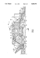
- FIG. 1 is a longitudinal sectional view of a mobile machine permitting the, cold production of covered aggregates and the production of surface coating using these aggregates.
- FIG. 2 is a section through 2--2 in FIG. 1.
- FIG. 3 is a longitudinal sectional view of a mobile machine permitting the production of a surface coating using hot-produced aggregates.
- the mobile machine of the invention is, in general, similar to the device which is the subject of French Patent 2,550,248.
- FIG. 1 shows the device of the invention in its working position on site, and the tipper (or pouring) section of a truck as it supplies loose chips into a hopper of this device.
- the device comprises a chassis 1 resting on four sets of wheels 2a, 2b, 2c, 2d.
- the axles of the sets 2c and 2d are driven by means of drive axles which are operatively connected to a drive unit having a motor 5 associated with a gear box 6.
- the drive unit makes it possible to move the machine both on the road and on site, and is described in detail in French Patent 2,550,248.
- the machine moves over the ground 7 of the site, consisting of the upper surface of a road on which a layer of coating 8 is produced using the method according to the invention.
- the chassis 1 carries a control cab 10 whose width is less than half the width of the chassis and which occupies a position which is offset towards one of the lateral sides of the chassis.
- a bucket elevator 12, inserted between the two side members of the chassis 1, is located in a position which is adjacent to the cab 10 and centrally located relative to the chassis.
- a receiving hopper 14 is located at the front of the machine just above the ground 7, and is fixed to the ends of the side members of the chassis 1 and communicates with the lower end of the bucket elevator 12.
- the bucket elevator 12 and receiving hopper 14 together define an automatic feeding mechanism for the machine.
- the bucket elevator 12 comprises a housing 17 and a set of buckets carried by two chains 18 which ascend towards the rear of the machine, such that they form an angle of about 60° with the plane of the chassis 1.
- An upper part of the chassis 17 communicates, via its discharge opening 19, with the upper part of a hopper 20 for storing granular materials, such as loose chips.
- bucket elevator could be replaced by an elevator of another type.
- the hopper 20 occupies most of the length of the machine and a substantial part of its width, at least in its upper part.
- a device known as a bar leveller, for distributing the loose chips makes it possible to spread the loose chips over the entire length and over the entire width of the storage hopper 20, and is located above the hopper 20 over its entire length.
- the bar leveller 31 consists of one or two endless chains trained about end pinions or pulleys and carrying transverse bars 23.
- the path of the bars of the leveller is very slightly tilted upwards, from front to rear.
- a screw leveller can be used instead of a bar leveller.
- the bucket elevator 12 and the bar leveller 31 are driven, in order to transport the loose chips 27, by hydraulic or electric motors by way of reduction gears (not shown).
- a tipper (or pouring) section 28 of a truck which is adapted to supply loose chips to the machine, is shown in FIG. 1 in its operative position for pouring chips into the receiving hopper 14.
- the chassis of the truck can be connected via a coupling device 29 to the machine, and the rear gate of the tipper section can be connected to a pivoting hook 30.
- the loose chips 27 are poured in a perfectly controlled manner into the receiving hopper 14 and are then transported by the bucket conveyor 18 to the upper part of the hopper 20 where the bar leveller 31 spreads the loose chips over the entire surface of the hopper 20, which has a large cross-section.
- this hopper can have a capacity of 10m 3 .
- a conveyor belt 34 is disposed under the hopper 20 and removes and measures, in terms of volume, the loose chips in the hopper 20 which are conveyed by the conveyor 34 to above an inlet opening of a mixer 35 into which the loose chips fall. Rollers which drive the conveyor 34 are driven in rotation by a hydraulic motor (not shown).
- Pulverulent material contained in a storage hopper 36, is also poured in a measured quantity into the opening of the mixer 35.
- the pulverulent material may consist of stone powder or fine sand and may be poured in a measured quantity into the mixer 35 simultaneously with the loose chips 27.
- the device comprises two lateral reservoirs 43 and 44 located on either side of the storage hopper 20.
- the reservoirs 43 and 44 are adapted to contain bituminous emulsions which may be different or identical.
- a boom 40 for spraying bituminous binding material consisting of the emulsion contained in one of the reservoirs 43 and 44, is fixed on the lower part of the chassis 1 under the mixer 35 and at the rear of the set of wheels 2d.
- the emulsion contained in the second reservoir is adapted to be fed into the mixer 35.
- the mixer 35 then mixes the loose chips coming from the storage hopper 20 with the pulverulent material coming from the hopper 36 and the bituminous emulsion conveyed to the mixer 35 from one of the reservoirs 43 and 44.
- the quantities of loose chips, pulverulent material and bituminous emulsion are measured so that aggregates are produced in the mixer 35 which consist of the loose chips covered with bitumen mixed with the pulverulent material in a proportion such that the aggregate has a pasty consistency.
- the proportion of bitumen relative to solid materials is less than 6% and the resulting product is in the form of aggregates which are distinct from one another and not in the form of a pasty mass, as in the case of the production of a bituminous coated product.
- Such aggregates consisting of loose chips covered with bitumen and mixed with a pulverulent material, may hereinafter be called dressed aggregates in order to distinguish them clearly from bituminous coated products which form an amorphous mass consisting of a mixture of the bitumen, aggregates, one or more sands and a pulverulent material, the aggregates being completely bound together by the bitumen, the pulverulent material and the sand which fill all the gaps between the aggregates.
- the dressed aggregates are poured onto the surface 7 of the road through the discharge opening of the mixer 35 upstream of a spreading and distributing device 41.
- a heating and vibrating surfacing table 42 is fixed in an articulated manner to the rear end 1a of the chassis 1, immediately behind the device 41 for distributing the dressed aggregates 45 cold-produced in the mixer 35.
- the table 42 of a type which is well-known to road work specialists, compacts and surfaces the aggregates in order to form the layer of coating 8 at the rear of the machine which moves in the direction and the sense of the arrow 46 (FIG. 1), this direction corresponding to the longitudinal direction of the site or road.
- the layer of coating 8 is produced in the manner which will be described hereinbelow.
- the boom 40 fed with bituminous emulsion from one of the lateral reservoirs of the mobile machine dispenses a layer of bituminous emulsion of constant thickness, by virtue of a set of spraying nozzles uniformly spaced in the direction of the boom 40 corresponding to the transverse direction of the machine, over the entire width of the road or of the carriageway.
- bituminous emulsion is dispensed at the rear of the last set of wheels 2d, so that the machine producing the coating never rolls over the layer of emulsion which has just been spread on the surface 7 of the road.
- the dressed aggregates emerging from the mixer 35 are dispensed onto the surface 7 of the road where they are spread in a first stage by the spreading and distributing device which preferably comprises an endless screw device 41.
- the vibrating and heating table 42 or finishing table compacts and surfaces the dressed aggregates which have just been dispensed onto the layer of bituminous binding material.
- the boom 40 for spraying the binding material, the zone in which the dressed aggregates 45 are dispensed, and the finishing table 42 are disposed close together, one after the other, at the rear part of the machine for producing the coating, which moves in the direction of the arrow 46.
- the distance between the boom 40 and the rear part of the finishing table 42 is such that, bearing in mind the speed of the machine corresponding to the speed of advance of the site, there are never more than five seconds between the spreading of the bituminous binding material on the surface 7 of the road and the completion of compacting and surfacing of the coating on the corresponding part of the road.
- the speed of advance of the site which corresponds to the speed of the machine in the direction of the arrow 46, is always greater than a value which is approximately equal to ten meters per minute, it being possible for this speed of advance to be of the order of twenty to twenty-five meters per minute.
- This speed which is much higher than the speed of advance of a finisher, in the case of the production of a layer of covering consisting of the prior art bituminous coated products, makes it possible to obtain a particularly good surfacing quality and a very effective reprofiling of the road during repair.
- the road is reprofiled by virtue of the formation of a coating which comprises a different number of superposed layers of loose chips according to the zones of this road which may comprise profile defects which are reflected in hollows of a considerable depth.
- the surfacing performed by the finishing table makes it possible to obtain a layer of coating whose upper surface is perfectly planar, because the hollows in the road are filled by a number of layers of superposed dressed aggregates which is sufficient to compensate for the level of the upper surface of the layer of coating.
- the aggregates in the successive layers bear directly on one another, which makes it possible to produce a material for filling those cavities which cannot be pressed out.
- the dressed aggregates are covered with a pasty layer which is both adhesive and lubricating, and are placed, without difficulty, on the surface of the road or on a lower layer of aggregates by sliding which is enhanced by the dressing layer.
- the speed of displacement, which is greater than ten meters per minute, of the finishing table makes it possible to enhance the displacement and placing of the layers of aggregates.
- the dressed aggregates coated with a pasty and adhesive layer based on bitumen are immediately fixed, one on top of the other, at the time of compacting, so well that any operational rejection is prevented. Moreover, compacting is greatly facilitated by the fact that the loose chips are coated with a lubricating bituminous layer. It is thus possible to use the road for vehicular traffic very soon after the production of the coating.
- the coating obtained makes it possible to reduce the vehicle traffic noise as the surface roughness of the loose chips no longer exists and as the cavities between the loose chips absorb the sound waves.
- the coating obtained using the process according to the invention provides good adhesion for vehicles, even in wet weather, as it has roughness and surface cavities.
- FIG. 3 shows an alternative embodiment of the device described hereinabove and shown in FIGS. 1 and 2.
- the device shown in FIG. 3, whose general structure is similar to that of the mobile device described in French Patent 2,550,248, is intended to be used for producing a coating according to the invention of dressed aggregates produced by hot mixing of dried and heated loose chips, bitumen and pulverulent material in an installation performed by other than the machine which produces the coating.
- the dressed aggregates can be produced, for example, in a conventional hot-coating drum and then transported to the site by dump trucks which are fixed to the front of the coating machine at the hopper 14 in order to pour the hot dressed aggregates into this hopper from the pouring section 28' of the truck. This operation is performed in the same manner as the pouring of the loose chips 27 in the embodiment of FIG. 1.
- the dressed aggregates 50 poured into the hopper 14 carried upwardly by a bar conveyor 12' and then poured into the central hopper 20 at the discharge end of the conveyor 12'.
- a rung conveyor 34' transports the hot dressed aggregates to the rear of the machine where the aggregates 50 are dispensed onto the surface 7 of the road.
- the central hopper 20 may comprise a bar leveller or a screw leveller similar to the leveller 31 in order to increase the storage capacity of the hopper 20.
- the hopper 36 for storing pulverulent material in the first embodiment is replaced, in this second embodiment, by a tank 51 intended to contain the bituminous binding material which may consist of an emulsion.
- the device shown in FIG. 3 includes lateral reservoirs similar to the reservoirs 43 and 44 of the device shown in FIGS. 1 and 2. These reservoirs, and the tank 51, can contain bituminous binding material, such as an emulsion, intended to be spread over the surface 7 of the road, using a variable width spreading boom 52 fixed to the chassis 1 of the machine at the rear of the rear set of wheels 2d.
- bituminous binding material such as an emulsion
- a 15-ton aggregate reserve can be disposed in the central hopper and a 12-ton binding material reserve can be stored in the lateral reservoirs and in the rear tank 51.
- the rear part 1a of the chassis 1 of the machine shown in FIG. 3 carries a vibrating and heating finishing table 42.
- the table 42 is mounted in an articulated manner on the chassis by means of a three point hitch.
- the boom 52 for spreading the binding material and the finishing table 42 are located on the rear part of the chassis 1 so that no more than 5 seconds elapses between the spreading of the binding material on the surface 7 of the road by the boom 52 and the end of compacting and surfacing performed by the finishing table 42, bearing in mind the speed of advance of the machine.
- the hot dressed aggregates 50 are poured out at a point located between the spreading boom 52 and the finisher 42, and slightly in front of an endless-screw distribution device 41.
- the dressed aggregates are at a temperature which is generally greater than 120° C. and which may be in the region of 150° C. when they are spread over the layer of bituminous binding material dispensed by the boom 52 over the surface 7 of the road.
- the speed of advance of the machine shown in FIG. 3, in the direction and the sense of the arrow 46, must be greater than ten meters per minute in order to obtain a perfectly surfaced layer of coating 8 providing an effective reprofiling of the road.
- the advantages are at least equivalent to the advantages obtained when implementing the method by making use of the machine shown in FIGS. 1 and 2.
- the quantity of bitumen contained in the layer of binding material spread over the road before the spreading of the dressed aggregates is slightly less than the quantity of bitumen poured over the road in order to produce the adhesion of dry loose chips in the prior art, and can, in fact, be two to four times less.
- the dressed aggregates are covered with a relatively thick and pasty layer consisting of bitumen and pulverulent material. 2 to 6% of bitumen and, as pulverulent material, either 4 to 5% by weight of stone powder or 10 to 20% of fine sand is incorporated with the loose chips.
- the function of the stone powder or the sand is only to make the fluid bitumen pasty and to thicken the adhesive layer so that the loose chips adhere together in a thicker layer.
- bitumen-coated loose chips are surrounded only by a thin film of hot bitumen, which is thus very fluid and which has a tendency to flow.
- the stone powder (or the fine sand) is added only to make the bitumen, which is too fluid, pasty and to thicken the layer of binding material, which is much too thin to guarantee durable binding between the particles.
- the thickening agent added is thus added for a dual purpose:
- composition of a surface coating according to the prior art comprising two superposed layers (two-layer coating) and the composition of a coating according to the invention will be given hereinbelow.
- the surface coating according to the prior art comprises a first layer of bitumen emulsion spread at the rate of 1.1 kg/m 2 , that is to say 0.8 kg of pure bitumen per square meter.
- a first layer of loose chips with a large particle size is spread over the layer of emulsion.
- This first layer comprises 7 kg of large loos chips per square meter.
- a second layer of emulsion is spread over this first layer of loose chips at the rate of 1.5 kg of emulsion per square meter, that is to say 1 kg of pure bitumen per square meter.
- a second layer of loose chips with a fine particle size is spread over this second layer of emulsion at the rate of 8 kg of fine loose chips per square meter.
- the coating according to the prior art undergoes compacting, after which a relatively large proportion of loose chips are not sufficiently bound to the surface of the road by the bituminous binding material, such that these loose chips risk being thrown up when vehicles pass by.
- the coating method according to the invention consists in spreading a layer of bitumen emulsion over the surface of the road at the rate of 0.95 kg of emulsion per square meter, i.e. 0.60 kg of pure bitumen per square meter.
- a layer of dressed loose chips is spread over this layer of emulsion at the rate of 22 kg of dressed loose chips per square meter.
- the dressed loose chips are dispensed onto the layer of bituminous binding material immediately after it is applied and the layer of dressed loose chips is actually compacted and smoothed immediately after the spreading of the dressed loose chips.
- the quantity of bitumen covering the dressed loose chips is 1.4 kg per square meter of coating.
- the bitumen covering the dressed aggregates is thickened by being mixed with 5 to 6 kg of fine sand or 1 to 2 kg of stone powder per square meter of coating.
- the total quantity of bitumen relative to the solid materials is thus in the region of 5%, which represents approximately the upper limit of the proportion of bitumen spread on the loose chips for forming the dressed aggregates according to the invention.
- the quantity of bituminous binding material used to produce the dressed aggregates from loose chips may be a good deal less than the quantity indicated hereinabove which corresponds substantially to the upper limit for implementation of the invention.
- the quantity of bitumen used for dressing the aggregates must be sufficient to avoid any rejection and any ejection of loose chips after production of the coating.
- the quantity of bitumen used for dressing the loose chips must represent at least 11% of the total quantity of bituminous binding material used per square meter of finished coating.
- bitumen contained in the bituminous binding material spread over the surface of the road before spreading of the dressed aggregates may represent up to 89% of the total quantity of bitumen.
- the quantity of bitumen contained in the binding material must not be less than 11% of the total quantity of bitumen used per square meter of coating.
- the aggregates may thus contain up to 89% of the total quantity of bitumen used.
- the quantity of bitumen contained in the binding material is greater than 20% of the total quantity of bitumen used.
- This quantity of bitumen in the binding material is preferably in the region of 30% of the total quantity of bitumen used.
- the proportion of bitumen relative to the weight of solid materials is generally between 2 and 6%.
- the method according to the invention may be implemented by making use of a bituminous binding material other than an emulsion and, for example, by making use of the bitumen incorporated in a solvent or, alternatively, of hot liquid bitumen.
- the method according to the invention can be implemented regardless of the particle size of the loose chips used to form the coating, within the limit of the particle sizes usually used to produce coatings according to the prior art.
- crushed rock loose chips use may advantageously be made of crushed products from the demolition of old bituminous road layers, these recycled products generally being known as millings.
- material is saved both in respect of the loose chips and bitumen used in the method according to the invention.
- the layer of solid bitumen which remains fixed to the milling to form the pasty coating for the aggregates.
- the method according to the invention may be implemented by making use of machines which are slightly different from those which have been described.
- the totally integrated design of these machines for producing and laying a coating makes it possible, however, to implement the invention under optimum conditions, avoiding any error in adjustment of the parameters required for producing a coating of satisfactory quality.
Abstract
Description
______________________________________
         Coating according
         to the prior art
                    Coating according
         (two-layer)
                    to the invention
______________________________________
Total quantity
           1.8 kg/m.sup.2
                        2.00 kg/m.sup.2
of bitumen
Quantity of
           1.8 kg/m.sup.2
                        0.60 kg/m.sup.2
bitumen spread
over the ground
Quantity of
           0            1.4 kg/m.sup.2
bitumen used to
dress the
aggregates
Total thickness
           15 mm at any 10 to 40 mm depending
of the covering
           point        on the defects of the
                        old support
Total quantity
           17 kg of large
                        22 kg of medium-sized
of loose chips
           loose chips +
                        loose chips
used (per m.sup.2)
           8 kg of small
           loose chips =
           25 kg
Other additives
           if appropriate,
                        an obligatory 5 to
           adhesion additive
                        6 kg of fine sand or
           at the loose 1 to 2 kg of stone
           chips/binding
                        powder in order to
           material interface
                        thicken the bitumen
Total quantity
           25 kg        23 to 28 kg
of solid
material of
mineral origin
______________________________________
Claims (17)
Applications Claiming Priority (2)
| Application Number | Priority Date | Filing Date | Title |
|---|---|---|---|
| FR8909893 | 1989-07-21 | ||
| FR8909893A FR2650005B1 (en) | 1989-07-21 | 1989-07-21 | METHOD AND DEVICE FOR PRODUCING A SURFACE COATING ON A SURFACE SUCH AS A PAVEMENT |
Publications (1)
| Publication Number | Publication Date |
|---|---|
| US5069578A true US5069578A (en) | 1991-12-03 |
Family
ID=9384043
Family Applications (1)
| Application Number | Title | Priority Date | Filing Date |
|---|---|---|---|
| US07/556,256 Expired - Lifetime US5069578A (en) | 1989-07-21 | 1990-07-19 | Method and device for producing a surface coating on a surface such as a road |
Country Status (12)
| Country | Link |
|---|---|
| US (1) | US5069578A (en) |
| EP (1) | EP0409700B1 (en) |
| AT (1) | ATE114757T1 (en) |
| CA (1) | CA2021648C (en) |
| DE (2) | DE409700T1 (en) |
| DK (1) | DK0409700T3 (en) |
| ES (1) | ES2067707T3 (en) |
| FI (1) | FI97308C (en) |
| FR (1) | FR2650005B1 (en) |
| GR (1) | GR3015184T3 (en) |
| NO (1) | NO179110C (en) |
| PT (1) | PT94769B (en) |
Cited By (33)
| Publication number | Priority date | Publication date | Assignee | Title |
|---|---|---|---|---|
| US5178486A (en) * | 1990-06-21 | 1993-01-12 | Colas S.A. | Device for spreading a fluid substance, and machine permitting the simultaneous application of this substance and of the surfacing of a highway |
| US5407299A (en) * | 1993-01-19 | 1995-04-18 | Sutton; John S. | Cement slurry mixing apparatus and method of using cement slurry |
| AU669260B2 (en) * | 1994-02-21 | 1996-05-30 | Screg | Method of producing an ultrathin bituminous road surfacing |
| US5851085A (en) * | 1994-09-29 | 1998-12-22 | Astec Industries, Inc. | Method and apparatus for spraying a tack material from a paving machine having a gravity feed hopper |
| US5895173A (en) * | 1996-07-26 | 1999-04-20 | E. D. Etnyre & Co. | Roadway paving apparatus |
| US6033147A (en) * | 1993-11-27 | 2000-03-07 | Richter; Elk | Method for producing a two-layer asphaltic surfacing |
| US6079901A (en) * | 1997-08-12 | 2000-06-27 | Midland Machinery Co., Inc | Paving machine capable of spraying a liquid binding material |
| US6332736B1 (en) * | 1999-04-08 | 2001-12-25 | James Cape And Sons Company | Method and apparatus for spreading paving materials |
| FR2813619A1 (en) * | 2000-09-01 | 2002-03-08 | Sacer | Procedure and machine for making cold bitumen-bound materials for road surfacing uses initial phase with water added to mixed components |
| US6444258B1 (en) | 2000-07-14 | 2002-09-03 | Phillip Rand Terry | Method of treating a pavement surface and apparatus for performing such method |
| WO2002099198A1 (en) | 2001-06-04 | 2002-12-12 | E.D. Etnyre & Co. | Roadway paving system and method including roadway paving vehicle and supply truck |
| US6513447B1 (en) * | 2001-01-16 | 2003-02-04 | Richard Guzman | Method and apparatus for distributing soil amendments |
| US6514007B2 (en) | 1993-11-27 | 2003-02-04 | Elk Richter | Finisher to lay and compact asphalt layers and method for operating same |
| FR2832743A1 (en) * | 2001-11-28 | 2003-05-30 | Chambard | Machine for simultaneous spreading of road chips and binder on ground comprises chassis supporting chip storage and regulation hoppers, binder tank and manifold and conveyor transferring chips between hoppers |
| FR2842542A1 (en) * | 2002-07-22 | 2004-01-23 | Chambard | Self-propelled vehicle for transferring road stone to a spreading machine used in construction or repairing of road, includes pivotal coupling with hook for engaging fixing element on rear of dump truck to maintain spacing between vehicles |
| US20040151545A1 (en) * | 2002-11-25 | 2004-08-05 | Famaro | Device for spreading liquid binder and roadstone behind a road making machine |
| US20040244646A1 (en) * | 2000-02-25 | 2004-12-09 | Kolo Veidekke A.S. | Process and system for production of a warm foam mix asphalt composition |
| US20060070695A1 (en) * | 2004-08-25 | 2006-04-06 | James Barnat | Method of selecting a binder for a chipsealing process based on its adhesion index |
| US20080268144A1 (en) * | 2007-04-26 | 2008-10-30 | Wilson Jack H | Apparatus and method for applying coatings to a surface |
| US20080292398A1 (en) * | 2007-05-23 | 2008-11-27 | Caterpillar Inc. | Transfer machine, system and paving material transfer method |
| US20090097918A1 (en) * | 2007-10-15 | 2009-04-16 | Larry Larson | Seal Coat Process Utilizing Multiple Applications of Asphalt Binder & Aggregate |
| US20090269134A1 (en) * | 2008-04-28 | 2009-10-29 | Jon Brett Wingo | Rut resistant coating and method of applying rut resistant coating |
| US20110038668A1 (en) * | 2009-08-13 | 2011-02-17 | Road Science, Llc. | Crack resistant coating and method of applying crack resistant coating |
| US20110206455A1 (en) * | 2010-02-24 | 2011-08-25 | Blacklidge Emulsions, Inc. | Hot applied tack coat |
| US20120275860A1 (en) * | 2011-04-26 | 2012-11-01 | Road Science, Llc | Destabilized bituminous bonding layer |
| US20150259864A1 (en) * | 2012-10-24 | 2015-09-17 | Gestion Bprr Inc. | Pothole repair product and mobile apparatus and method of manufacturing an asphalt patch |
| US20170138000A1 (en) * | 2014-06-26 | 2017-05-18 | Colas | Device for spreading a bituminous coating from a film of determined width of the coating, and method for implementing same |
| US9765487B2 (en) * | 2015-09-08 | 2017-09-19 | Baldwin Paving Co., Inc. | Systems for applying roadway surface treatments, and methods of using same |
| US10094074B2 (en) | 2016-03-18 | 2018-10-09 | The Gorman Group Llc | Machine, system and method for resurfacing existing roads |
| RU194100U1 (en) * | 2019-09-16 | 2019-11-28 | Дмитрий Валентинович Челядинов | BINDER DISTRIBUTION DEVICE |
| US10889941B1 (en) | 2015-03-23 | 2021-01-12 | Venture Corporation | Spray paving coating and method |
| US10975530B2 (en) | 2016-03-18 | 2021-04-13 | The Gorman Group Llc | Machine, system and method for resurfacing existing roads using premixed stress absorbing membrane interlayer (SAMI) material |
| US11214930B2 (en) * | 2018-02-19 | 2022-01-04 | McAnany Construction, Inc. | System and method for modifying and repaving paved surfaces |
Families Citing this family (13)
| Publication number | Priority date | Publication date | Assignee | Title |
|---|---|---|---|---|
| FR2675522B1 (en) * | 1991-04-17 | 1993-12-10 | Screg Routes Travaux Publics | DEVICE FOR PRODUCING A ROAD COVERING BY SUCCESSIVE SPREADING ONTO THE ROAD SURFACE TO BE COVERED, A HANGING LAYER AND A LAYER OF HOT BITUMINOUS MATERIAL. |
| FR2677383A1 (en) * | 1991-06-04 | 1992-12-11 | Colas Sa | FINISHER TYPE PAVEMENT CONSTRUCTION MACHINE. |
| GB2291087B (en) | 1994-07-09 | 1997-08-06 | Adrian Holt | A continuous mobile production and laying process for thin macadam surfacing |
| EP0771910A1 (en) * | 1995-10-17 | 1997-05-07 | Jacques Meunier | Method for producing a composite material for roads |
| FR2847599B1 (en) * | 2002-11-27 | 2005-09-23 | Famaro | DEVICE AND METHOD FOR MANUFACTURING AND APPLYING TO A ROAD SURFACE OF A COOL COLD WINDOW |
| FR2909393B1 (en) * | 2006-12-01 | 2010-02-19 | Concept Travaux Publics | MACHINE FOR SPREADING LIQUIDS AND MATERIALS ON A PAVEMENT |
| EP2119831B1 (en) | 2008-05-14 | 2016-03-30 | Joseph Vögele AG | Paver |
| US8562247B2 (en) | 2009-01-02 | 2013-10-22 | Heatwurx, Inc. | Asphalt repair system and method |
| US8556536B2 (en) | 2009-01-02 | 2013-10-15 | Heatwurx, Inc. | Asphalt repair system and method |
| US9416499B2 (en) | 2009-12-31 | 2016-08-16 | Heatwurx, Inc. | System and method for sensing and managing pothole location and pothole characteristics |
| US8801325B1 (en) | 2013-02-26 | 2014-08-12 | Heatwurx, Inc. | System and method for controlling an asphalt repair apparatus |
| USD700633S1 (en) | 2013-07-26 | 2014-03-04 | Heatwurx, Inc. | Asphalt repair device |
| CN111705580A (en) * | 2020-06-10 | 2020-09-25 | 四川轻化工大学 | Green dust-settling environment-friendly construction structure for road and construction method thereof |
Citations (6)
| Publication number | Priority date | Publication date | Assignee | Title |
|---|---|---|---|---|
| GB396625A (en) * | 1932-01-25 | 1933-08-10 | Alphonse Joseph Schars | Improvements in or relating to apparatus for treating roads and other surfaces |
| US4011023A (en) * | 1975-12-15 | 1977-03-08 | Cutler Repaving, Inc. | Asphalt pavement recycling apparatus |
| US4124325A (en) * | 1975-12-31 | 1978-11-07 | Cutler Repaving, Inc. | Asphalt pavement recycling apparatus |
| EP0132202A1 (en) * | 1983-07-13 | 1985-01-23 | Ermont S.A. | Mobile device for the in situ cold mixing and spreading of bitumen-coated products for road surfacings |
| EP0292337A1 (en) * | 1987-02-24 | 1988-11-23 | Screg Routes Et Travaux Publics | Apparatus for spreading a bituminous emulsion on a road surface without lorries circulating over the adhesion layer formed by spreading this emulsion |
| EP0316752A1 (en) * | 1987-11-18 | 1989-05-24 | Egli Ag | Apparatus for reconstructing layers of road surfacings |
-
1989
- 1989-07-21 FR FR8909893A patent/FR2650005B1/en not_active Expired - Fee Related
-
1990
- 1990-07-12 AT AT90402019T patent/ATE114757T1/en not_active IP Right Cessation
- 1990-07-12 DE DE90402019T patent/DE409700T1/en active Pending
- 1990-07-12 DE DE69014459T patent/DE69014459T2/en not_active Expired - Fee Related
- 1990-07-12 ES ES90402019T patent/ES2067707T3/en not_active Expired - Lifetime
- 1990-07-12 DK DK90402019.5T patent/DK0409700T3/en active
- 1990-07-12 EP EP90402019A patent/EP0409700B1/en not_active Expired - Lifetime
- 1990-07-19 PT PT94769A patent/PT94769B/en not_active IP Right Cessation
- 1990-07-19 US US07/556,256 patent/US5069578A/en not_active Expired - Lifetime
- 1990-07-19 NO NO903227A patent/NO179110C/en not_active IP Right Cessation
- 1990-07-19 FI FI903649A patent/FI97308C/en active IP Right Grant
- 1990-07-20 CA CA002021648A patent/CA2021648C/en not_active Expired - Lifetime
-
1995
- 1995-02-27 GR GR940403890T patent/GR3015184T3/en unknown
Patent Citations (7)
| Publication number | Priority date | Publication date | Assignee | Title |
|---|---|---|---|---|
| GB396625A (en) * | 1932-01-25 | 1933-08-10 | Alphonse Joseph Schars | Improvements in or relating to apparatus for treating roads and other surfaces |
| US4011023A (en) * | 1975-12-15 | 1977-03-08 | Cutler Repaving, Inc. | Asphalt pavement recycling apparatus |
| US4124325A (en) * | 1975-12-31 | 1978-11-07 | Cutler Repaving, Inc. | Asphalt pavement recycling apparatus |
| EP0132202A1 (en) * | 1983-07-13 | 1985-01-23 | Ermont S.A. | Mobile device for the in situ cold mixing and spreading of bitumen-coated products for road surfacings |
| FR2550248A1 (en) * | 1983-07-13 | 1985-02-08 | Creusot Loire | MOBILE DEVICE FOR COLD WINDING AND ROAD SPREADING OF BITUMINOUS COATED PRODUCTS FOR ROAD COVERINGS |
| EP0292337A1 (en) * | 1987-02-24 | 1988-11-23 | Screg Routes Et Travaux Publics | Apparatus for spreading a bituminous emulsion on a road surface without lorries circulating over the adhesion layer formed by spreading this emulsion |
| EP0316752A1 (en) * | 1987-11-18 | 1989-05-24 | Egli Ag | Apparatus for reconstructing layers of road surfacings |
Non-Patent Citations (2)
| Title |
|---|
| Complete Specification Improved Manufacture of Bituminous Compositions, No. 682B, Gr. Britian. * |
| Complete Specification-Improved Manufacture of Bituminous Compositions, No. 682B, Gr. Britian. |
Cited By (58)
| Publication number | Priority date | Publication date | Assignee | Title |
|---|---|---|---|---|
| US5178486A (en) * | 1990-06-21 | 1993-01-12 | Colas S.A. | Device for spreading a fluid substance, and machine permitting the simultaneous application of this substance and of the surfacing of a highway |
| US5407299A (en) * | 1993-01-19 | 1995-04-18 | Sutton; John S. | Cement slurry mixing apparatus and method of using cement slurry |
| US6514007B2 (en) | 1993-11-27 | 2003-02-04 | Elk Richter | Finisher to lay and compact asphalt layers and method for operating same |
| US6033147A (en) * | 1993-11-27 | 2000-03-07 | Richter; Elk | Method for producing a two-layer asphaltic surfacing |
| AU669260B2 (en) * | 1994-02-21 | 1996-05-30 | Screg | Method of producing an ultrathin bituminous road surfacing |
| US5851085A (en) * | 1994-09-29 | 1998-12-22 | Astec Industries, Inc. | Method and apparatus for spraying a tack material from a paving machine having a gravity feed hopper |
| US5895173A (en) * | 1996-07-26 | 1999-04-20 | E. D. Etnyre & Co. | Roadway paving apparatus |
| US6079901A (en) * | 1997-08-12 | 2000-06-27 | Midland Machinery Co., Inc | Paving machine capable of spraying a liquid binding material |
| US6332736B1 (en) * | 1999-04-08 | 2001-12-25 | James Cape And Sons Company | Method and apparatus for spreading paving materials |
| US20040244646A1 (en) * | 2000-02-25 | 2004-12-09 | Kolo Veidekke A.S. | Process and system for production of a warm foam mix asphalt composition |
| US6846354B2 (en) | 2000-02-25 | 2005-01-25 | Kolo Veidekke A.S. | Process and system for production of a warm foam mix asphalt composition |
| US6444258B1 (en) | 2000-07-14 | 2002-09-03 | Phillip Rand Terry | Method of treating a pavement surface and apparatus for performing such method |
| FR2813619A1 (en) * | 2000-09-01 | 2002-03-08 | Sacer | Procedure and machine for making cold bitumen-bound materials for road surfacing uses initial phase with water added to mixed components |
| US6513447B1 (en) * | 2001-01-16 | 2003-02-04 | Richard Guzman | Method and apparatus for distributing soil amendments |
| US6776557B2 (en) | 2001-06-04 | 2004-08-17 | E.D. Etnyre & Co. | Roadway paving supply truck |
| AU2002310150B2 (en) * | 2001-06-04 | 2007-05-31 | Arr-Maz Products, L.P. | Roadway paving system and method including roadway paving vehicle and supply truck |
| EP1392930A1 (en) * | 2001-06-04 | 2004-03-03 | E.D. Etnyre & Co. | Roadway paving system and method including roadway paving vehicle and supply truck |
| EP1392930A4 (en) * | 2001-06-04 | 2007-12-12 | Semmaterials Lp | Roadway paving system and method including roadway paving vehicle and supply truck |
| WO2002099198A1 (en) | 2001-06-04 | 2002-12-12 | E.D. Etnyre & Co. | Roadway paving system and method including roadway paving vehicle and supply truck |
| US6805516B2 (en) * | 2001-06-04 | 2004-10-19 | E.D. Etnyre & Co. | Roadway paving system and method including roadway paving vehicle and supply truck |
| WO2003046288A1 (en) * | 2001-11-28 | 2003-06-05 | Chambard | Machine for simultaneously spreading gravel and binder on the ground |
| FR2832743A1 (en) * | 2001-11-28 | 2003-05-30 | Chambard | Machine for simultaneous spreading of road chips and binder on ground comprises chassis supporting chip storage and regulation hoppers, binder tank and manifold and conveyor transferring chips between hoppers |
| FR2842542A1 (en) * | 2002-07-22 | 2004-01-23 | Chambard | Self-propelled vehicle for transferring road stone to a spreading machine used in construction or repairing of road, includes pivotal coupling with hook for engaging fixing element on rear of dump truck to maintain spacing between vehicles |
| US6802464B2 (en) * | 2002-11-25 | 2004-10-12 | Famaro | Device for spreading liquid binder and roadstone behind a road making machine |
| US20040151545A1 (en) * | 2002-11-25 | 2004-08-05 | Famaro | Device for spreading liquid binder and roadstone behind a road making machine |
| US20060070695A1 (en) * | 2004-08-25 | 2006-04-06 | James Barnat | Method of selecting a binder for a chipsealing process based on its adhesion index |
| US7279035B2 (en) | 2004-08-25 | 2007-10-09 | Semmaterials, Lp | Method of selecting a binder for a chipsealing process based on its adhesion index |
| US7963719B2 (en) * | 2007-04-26 | 2011-06-21 | Wilson Sr Jack H | Apparatus and method for applying coatings to a surface |
| US20080268144A1 (en) * | 2007-04-26 | 2008-10-30 | Wilson Jack H | Apparatus and method for applying coatings to a surface |
| US20080292398A1 (en) * | 2007-05-23 | 2008-11-27 | Caterpillar Inc. | Transfer machine, system and paving material transfer method |
| US20090097918A1 (en) * | 2007-10-15 | 2009-04-16 | Larry Larson | Seal Coat Process Utilizing Multiple Applications of Asphalt Binder & Aggregate |
| US7798744B2 (en) * | 2007-10-15 | 2010-09-21 | Road Science, L.L.C. | Seal coat process utilizing multiple applications of asphalt binder and aggregate |
| WO2009134306A1 (en) * | 2008-04-28 | 2009-11-05 | Road Science, Llp | Rut resistant coating and method of applying rut resistant coating |
| US7802941B2 (en) | 2008-04-28 | 2010-09-28 | Road Science, L.L.C. | Rut resistant coating and method of applying rut resistant coating |
| US20090269134A1 (en) * | 2008-04-28 | 2009-10-29 | Jon Brett Wingo | Rut resistant coating and method of applying rut resistant coating |
| EP2464789A4 (en) * | 2009-08-13 | 2014-08-20 | Arr Maz Products Lp | Crack resistant coating and method of applying crack resistant coating |
| US20110142540A1 (en) * | 2009-08-13 | 2011-06-16 | Road Science, Llc | Crack resistant coating and method of applying crack resistant coating |
| EP2464789A1 (en) * | 2009-08-13 | 2012-06-20 | Arr-Maz Products, L.P. | Crack resistant coating and method of applying crack resistant coating |
| US20110142538A1 (en) * | 2009-08-13 | 2011-06-16 | Road Science, Llc | Crack resistant coating and method of applying crack resistant coating |
| US8329250B2 (en) * | 2009-08-13 | 2012-12-11 | Arr-Maz Products, L.P. | Crack resistant coating and method of applying crack resistant coating |
| US8465843B2 (en) | 2009-08-13 | 2013-06-18 | Arr-Maz Products, L.P. | Crack resistant coating and method of applying crack resistant coating |
| US20110038668A1 (en) * | 2009-08-13 | 2011-02-17 | Road Science, Llc. | Crack resistant coating and method of applying crack resistant coating |
| US10273637B2 (en) * | 2010-02-24 | 2019-04-30 | Blacklidge Emulsions, Inc. | Hot applied tack coat |
| US20110206455A1 (en) * | 2010-02-24 | 2011-08-25 | Blacklidge Emulsions, Inc. | Hot applied tack coat |
| WO2011106562A2 (en) | 2010-02-24 | 2011-09-01 | Blacklidge Emulsions, Inc. | Hot applied tack coat |
| US20120275860A1 (en) * | 2011-04-26 | 2012-11-01 | Road Science, Llc | Destabilized bituminous bonding layer |
| US9587358B2 (en) * | 2012-10-24 | 2017-03-07 | Gestion Acbk Inc. | Pothole repair product and mobile apparatus and method of manufacturing an asphalt patch |
| US20150259864A1 (en) * | 2012-10-24 | 2015-09-17 | Gestion Bprr Inc. | Pothole repair product and mobile apparatus and method of manufacturing an asphalt patch |
| US20170138000A1 (en) * | 2014-06-26 | 2017-05-18 | Colas | Device for spreading a bituminous coating from a film of determined width of the coating, and method for implementing same |
| US10889941B1 (en) | 2015-03-23 | 2021-01-12 | Venture Corporation | Spray paving coating and method |
| US11560674B2 (en) | 2015-03-23 | 2023-01-24 | Venture Corporation | Spray paving coating and method |
| US9765487B2 (en) * | 2015-09-08 | 2017-09-19 | Baldwin Paving Co., Inc. | Systems for applying roadway surface treatments, and methods of using same |
| US10233596B2 (en) * | 2015-09-08 | 2019-03-19 | Baldwin Paving Co., Inc. | Systems for applying roadway surface treatments, and methods of using same |
| US10094074B2 (en) | 2016-03-18 | 2018-10-09 | The Gorman Group Llc | Machine, system and method for resurfacing existing roads |
| US10781561B2 (en) | 2016-03-18 | 2020-09-22 | The Gorman Group Llc | Machine, system and method for resurfacing existing roads |
| US10975530B2 (en) | 2016-03-18 | 2021-04-13 | The Gorman Group Llc | Machine, system and method for resurfacing existing roads using premixed stress absorbing membrane interlayer (SAMI) material |
| US11214930B2 (en) * | 2018-02-19 | 2022-01-04 | McAnany Construction, Inc. | System and method for modifying and repaving paved surfaces |
| RU194100U1 (en) * | 2019-09-16 | 2019-11-28 | Дмитрий Валентинович Челядинов | BINDER DISTRIBUTION DEVICE |
Also Published As
| Publication number | Publication date |
|---|---|
| FI97308C (en) | 1996-11-25 |
| ES2067707T3 (en) | 1995-04-01 |
| EP0409700B1 (en) | 1994-11-30 |
| FI903649A0 (en) | 1990-07-19 |
| NO903227L (en) | 1991-01-22 |
| CA2021648A1 (en) | 1991-01-22 |
| EP0409700A1 (en) | 1991-01-23 |
| FI97308B (en) | 1996-08-15 |
| PT94769A (en) | 1991-03-20 |
| FR2650005B1 (en) | 1994-04-15 |
| CA2021648C (en) | 1998-08-11 |
| GR3015184T3 (en) | 1995-05-31 |
| ATE114757T1 (en) | 1994-12-15 |
| FR2650005A1 (en) | 1991-01-25 |
| NO179110C (en) | 1996-08-07 |
| DK0409700T3 (en) | 1995-01-16 |
| NO903227D0 (en) | 1990-07-19 |
| DE409700T1 (en) | 1993-11-25 |
| NO179110B (en) | 1996-04-29 |
| PT94769B (en) | 1997-10-31 |
| DE69014459T2 (en) | 1995-07-13 |
| DE69014459D1 (en) | 1995-01-12 |
Similar Documents
| Publication | Publication Date | Title |
|---|---|---|
| US5069578A (en) | Method and device for producing a surface coating on a surface such as a road | |
| EP1818455B1 (en) | Method for recycling asphalt mixture layer of pavement in place continuously and self-propelled vehicle system therefor | |
| US5735634A (en) | Road finisher and a method of applying surface layers | |
| US4974993A (en) | Method of renewing a road surface of bituminous mix, with cold application of the recycled covering material | |
| US20140270953A1 (en) | Road strengthening and reinforcement during a recycling process | |
| US20080193214A1 (en) | Method for Adding Foaming Agents to Pavement Aggregate | |
| US7287818B1 (en) | Vertical milling apparatus for a paved surface | |
| CN112982089B (en) | Ultrathin overlay asphalt mixture laying device | |
| CN211472012U (en) | Signal lamp crossing filling type composite pavement | |
| US6514007B2 (en) | Finisher to lay and compact asphalt layers and method for operating same | |
| CN111622050A (en) | Construction method for cold regeneration of mixture by adopting foamed asphalt and mixture mixing system | |
| Scherocman et al. | Placement of asphalt concrete mixtures in | |
| CN202202242U (en) | Seal machine for wide asphalt | |
| CN114016430A (en) | Asphalt concrete bridge deck pavement method | |
| CN109468904A (en) | A kind of pitch composite seal coat construction method for road in airport | |
| CN211171471U (en) | High-performance steel slag pavement | |
| CN206385430U (en) | A kind of construction equipment for being used to plant stone formula interlayer treatment | |
| CN212175372U (en) | Splicing structure between new and old road surfaces | |
| CN114381981A (en) | Construction method for double-layer combined paving test section of guide way | |
| US2068702A (en) | Pavement constructing | |
| JPH11152709A (en) | Spraying device of finisher | |
| CN110438861B (en) | Double-color asphalt pavement structure and construction process thereof | |
| CN111996876A (en) | Construction process for changing cement concrete pavement into asphalt pavement | |
| WO1999041456A1 (en) | Machine and method for the renewal of an asphalt surface | |
| EP0691433B1 (en) | Mobile apparatus and method for producing and laying a cold or emulsion macadam on a surface |
Legal Events
| Date | Code | Title | Description |
|---|---|---|---|
| AS | Assignment |
Owner name: SCREG ROUTES ET TRAVAUX PUBLICS, FRANCE Free format text: ASSIGNMENT OF ASSIGNORS INTEREST.;ASSIGNORS:PATTE, JEAN-FRANSOIS;BENSE, PIERRE;REEL/FRAME:005443/0612 Effective date: 19900723 |
|
| STCF | Information on status: patent grant |
Free format text: PATENTED CASE |
|
| FEPP | Fee payment procedure |
Free format text: PAYOR NUMBER ASSIGNED (ORIGINAL EVENT CODE: ASPN); ENTITY STATUS OF PATENT OWNER: LARGE ENTITY |
|
| FPAY | Fee payment |
Year of fee payment: 4 |
|
| FEPP | Fee payment procedure |
Free format text: PAYER NUMBER DE-ASSIGNED (ORIGINAL EVENT CODE: RMPN); ENTITY STATUS OF PATENT OWNER: LARGE ENTITY Free format text: PAYOR NUMBER ASSIGNED (ORIGINAL EVENT CODE: ASPN); ENTITY STATUS OF PATENT OWNER: LARGE ENTITY |
|
| FPAY | Fee payment |
Year of fee payment: 8 |
|
| FPAY | Fee payment |
Year of fee payment: 12 |
|
| REMI | Maintenance fee reminder mailed | ||
| AS | Assignment |
Owner name: ROAD SCIENCE, LLC,OKLAHOMA Free format text: ASSIGNMENT OF ASSIGNORS INTEREST;ASSIGNOR:SCREG ROUTES ET TRAVAUX PUBLICS (THROUGH ITS SUCCESSOR COLAS, S.A.);REEL/FRAME:024170/0758 Effective date: 20100401 |