BACKGROUND OF THE INVENTION
The present invention relates to a method of and an apparatus for operating a display screen, and more particularly to a method of and an apparatus for controlling a display device which is used for displaying a logical screen different in size from a physical screen and which has a function of zooming a displayed image.
In a display device for displaying a logical screen larger in size than a physical screen, only part of the logical screen is displayed on the physical screen. In this case, when it is indicated by one of input devices such as a keyboard and a pointing device (hereinafter referred to as "mouse") that a displayed area is to become narrower, an enlarged image of a character or figure is displayed on the physical screen. When the enlarged image is displayed, a displayed area of the logical screen corresponding to the physical screen becomes smaller than an initial displayed area of the logical screen. As a result, in some cases, a desired character or figure may vanish from the physical screen. In such cases, for example, a method has hitherto been used which is described in a Japanese Patent Application JP-A-55-78335. In this method, the displayed area is continuously moved in a desired direction until the desired character or figure is displayed on the physical screen.
In the above method, however, there arise three problems, a first one of which is that a zooming operation command and a displayed-area moving command are separately issued, and thus the number of operations increases. A second problem is that an operation is required to issue each of the zooming operation command and the displayed-area moving command a plurality of times till a desired area on the logical screen is displayed on the physical screen. This is because an enlarged or contacted image may be displayed in a state that the moving distance necessary for reaching the desired area on the logical screen is erroneously estimated or the movement for reaching the desired area on the logical screen is forgotten. A third problem is that it is required to display a plurality of areas of the logical screen on the physical screen till the desired area of the logical screen is displayed, and hence the amount of processing executed by a computer and the processing time thereof are increased.
SUMMARY OF THE INVENTION
A first object of the present invention is to provide a method of and an apparatus for operating a display device having a zooming function, in such a manner that an indication for requiring a zooming operation and an indication for specifying a desired logical area are given by a one-touch operation.
A second object of the present invention is to provide a method of and an apparatus for operating a display device having a zooming function, in which method and apparatus a desired logical area can be directly displayed on a physical screen without displaying any other logical area.
In order to attain the above objects, according to the present invention, there is provided a method of operating a display device having a zooming function which comprises the steps of: displaying on a physical screen a first frame similar in shape to a logical screen; displaying on the physical screen a second frame similar in shape to an area of the logical screen which is displayed on the physical screen; displaying on the physical screen a third frame similar in shape to an area of the logical screen which is to be subjected to a zooming operation; and moving the third frame to a desired position in the first frame by using one of a mouse and a keyboard.
When an operator selects an icon indicative of a zooming operation by using a coordinate input device such as a mouse, the first frame similar to the logical screen, the second frame similar to that area of the logical screen which is now displayed on a physical screen, and the third frame similar to that area of the logical screen which is to be subjected to a zooming operation, are all displayed on the physical screen at predetermined positions. Hence, the operator can readily know the present mapping relation between the logical screen and the physical screen from the first and second frames. Further, that area of the logical screen which is to be subjected to a zooming operation, can be predicted from the third frame.
When it is supposed that a desired character or figure may exist outside of a displayed area and thus may vanish from the physical screen, the operator moves the third frame to an appropriate position by using a mouse, and then a button of the mouse is released, to complete a desired indication.
As soon as the desired indication is completed, enlarged or contracted images of characters and figures which exist in a specified area, are displayed on the physical screen. That is, by using the above operating method, a zooming operation and a displayed-area changing operation can be specified at once.
Incidentally, the applicants has proposed a method of changing a displayed area, in U.S. Pat. No. 4,786,897 entitled "Display Screen Control Device", granted for a patent application Ser. No. 888,979.
BRIEF DESCRIPTION OF THE DRAWINGS
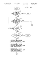
FIGS. 1(a)-1(e) show schematic diagrams for explaining the principle of the present invention.
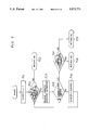
FIG. 2 is a block diagram showing the whole construction of an apparatus for controlling a display device in accordance with the present invention.
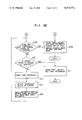
FIG. 3 is a block diagram showing a relation among various kinds of programs and data.
FIG. 4 is a schematic diagram showing the contents of the screen table of FIG. 3.
FIG. 5 is a schematic diagram showing the contents of the command table of FIG. 3.
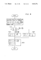
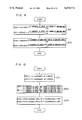
FIGS. 6A and 6b are flow charts showing the processing executed by a zooming main program.
FIG. 7 is a flow chart showing the processing executed by a command check program.
FIG. 8 is a flow chart showing the processing executed by a program for calculating the first rectangle position.
FIG. 9 is a flow chart showing the processing executed by a program for calculating the second rectangle position.
FIG. 10 is a flow chart showing the processing executed by a program for calculating the third rectangle position.
FIG. 11 is a flow chart showing the processing executed by a program for calculating the coordinates of a displayed area.
DESCRIPTION OF THE PREFERRED EMBODIMENT
An embodiment of the present invention will be explained below in detail, with reference to the drawings.
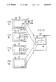
At first, the principle and outline of the present invention will be explained, with reference to FIG. 1. FIG. 1(a) shows an example of a display screen. A displayed area 105 on a logical screen 104 shown in FIG. 1(e) is displayed in a viewport 102 of a physical screen 101 shown in FIG. 1(a). In FIG. 1(a), reference numeral 103 designates an operation menu for the viewport 102. A zooming-operation indicating icon 106 is included in the above menu. In order to display an enlarged image in a state shown in FIG. 1(a), it is necessary to move a cursor 107 which is indicated by an arrow, by using a mouse 108 so that the cursor 107 is placed on the icon 106, and to depress a right button 109 mounted on the mouse 108. When the right button 109 is depressed, a command for making the magnification of image twice larger than the present magnification is issued. While, in order to display a contracted image, it is necessary to depress a left button 110 mounted on the mouse 108. When the left button 110 is depressed, a command for making the magnification of image equal to one-half the present magnification is issued. When an operator moves the cursor 107 as above while depressing the button 109 or 110 of the mouse 108, the state of the physical screen 101 is changed as shown in FIG. 1(b). That is, the first rectangular frame 111 for indicating the logical screen 104 is displayed in the viewport 102, the second rectangular frame 112 for indicating the position and size of the present displayed area 105 relative to the logical screen 104 is also displayed in the viewport 102, and further the third rectangular frame 115 for indicating the position and size of a logical area 113 which is to be enlarged or contracted, relative to the logical screen 104 is displayed in the viewport 102.
In a case where a desired character or figure exists in the logical area 113 and thus it is unnecessary to change the logical area 113, the button 109 or 110 of the mouse 108 is released. In a case where the desired character or figure exists outside of the logical area 113 and hence it is necessary to substitute a logical area 116 shown in FIG. 1(e) for the logical area 113, the operator moves the cursor 107 in a state that the button 109 or 110 of the mouse 8 is depressed, while observing the display screen of FIG. 1(e), to move the third rectangular frame 115 to a desired position 117 as shown in FIG. 1(c).
When the button 109 or 110 of the mouse 8 is released in a state that the third rectangular frame 115 has been moved to the position 117, an enlarged or contracted image of the newly displayed area 116 of the logical screen 104 is displayed in the viewport 102 of the physical screen 101, as shown in FIG. 1(d).
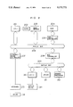
FIG. 2 is a block diagram showing the whole construction of an embodiment of an apparatus for controlling a display device in accordance with the present invention. In FIG. 2, reference numeral 201 designates a CPU (namely, central processing unit), 202 a clock signal generator, 203 a main memory for storing programs and data, 204 a disk, 205 a disk controller, 206 a system bus for transferring data which is used in the whole of the present embodiment, 207 a keyboard/mouse controller connected to a keyboard 213 and the mouse 108, 209 a display bus for transferring data which is used in a display system, 208 a bus controller for connecting the system bus 206 and the display bus 209, 212 a drawing processor, 211 a VRAM (namely, vides random access memory), and 210 a CRTC (namely, CRT controller) connected to a display device 214.
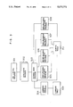
FIG. 3 shows a relation among various kinds of programs and data which are stored in the main memory 203. In FIG. 3, reference numeral 301 designates a job control program for controlling the execution of each of the following programs, 302 an application program, 303 a zooming main program, 304 a command check program for checking a command which is selected by the mouse, 305 a program for calculating the display position of the first rectangular frame 111, 306 a program for calculating the display position of the second rectangular frame 112, 307 a program for calculating the display position of the third rectangular frame 115, 308 a program for calculating a displayed area which is specified by the movement of the cursor, 309 a command table for indicating display positions of commands, and 310 a screen table for storing information on the logical and physical screens.
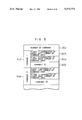
FIG. 4 shows the contents of the screen table 310. In FIG. 4, reference numeral 401 designates an area for storing the value of width LW of the logical screen 104, 402 an area for storing the value of height LH of the logical screen 104, 403 an area for storing the values of X- and Y-coordinates WX1 and WY1 of the upper left corner of the displayed area 105, 404 an area for storing the values of X- and Y-coordinates WX2 and WY2 of the lower right corner of the displayed area 105, 405 an area for storing the zooming ratio of X-coordinates, 406 an area for storing the zooming ratio of Y-coordinates, 407 an area for storing the values of X- and Y-coordinates VX1 and VY1 of the upper left corner of the viewport 102 included in the physical screen 101, 408 an area for storing the values of X- and Y-coordinates VX2 and VY2 of the lower right corner of the viewport 102, 409 an area for storing the values of X-and Y-coordinates R1X1 and R1Y1 of the upper left corner of the first rectangular frame 111, 410 an area for storing the values of X- and Y-coordinates R1X2 and R1Y2 of the lower right corner of the first rectangular frame 111, 411 an area for storing the values of X- and Y-coordinates R2X1 and R2Y1 of the upper left corner of the second rectangular frame 112, 412 an area for storing the values of X- and Y-coordinates R2X2 and R2Y2 of the lower right corner of the second rectangular frame 112, 413 an area for storing the values of X- and Y-coordinates R3X1 and R3Y1 of the upper left corner of the third rectangular frame 115, and 414 an area for storing the values of X- and Y-coordinates R3X2 and R3Y2 of the lower right corner of the third rectangular frame 115.
FIG. 5 shows the contents of the command table 308. In FIG. 5, reference numeral 501 designates an area for storing the number of commands, 502 an area for storing information on a command-1, and 506 an area for storing information on a command-2. The area 502 includes a sub-area 503 for storing the coordinate values of the upper left corner of a command indicating area (namely, command area) where the command-1 is indicated, a sub-area 504 for storing the coordinate values of the lower right corner of the above command area, and a sub-area 505 for storing a command ID indicative of the kind of the command-1. Although only the command-1 and command-2 are shown in FIG. 5, the command table 308 also contains information on a command-3 and so forth.
FIGS. 6A and 6b are flow charts which show the processing executed by the zooming main program. In step 601, the command check program 304 is read out from the main memory, to check whether or not the button of the mouse is depressed in a state the cursor is placed in the zooming icon 106. The command check program 304 will be explained later in detail, with reference to FIG. 7. In a case where the button is depressed in the above state, the processing in step 602 is carried out. While, in a case where the button is not depressed in the above state, processing terminates without requiring any other operation. In the step 602, it is checked whether or not the button is released in the state that the cursor exists in the zooming icon 106. When the button is released in the above state, the zooming processing in step 609 is carried out. While, in a case where the button is not released in the above state, the processing in step 603 is carried out. In the step 603, it is checked whether or not the cursor is moved to the outside of the zooming icon 106. When the cursor is moved to the outside of icon 106, the processing in step 604 is carried out. When the cursor is not moved to the outside of the icon 106, the processing in the step 602 is again carried out. In the step 604, it is checked whether or not the cursor 107 exists in the viewport 102. In more detail, it is checked whether or not the coordinate values of the cursor 107 exist in a range restricted by the X- and Y-coordinates VX1 and VY1 of the upper left corner of the viewport 102 and the X- and Y-coordinates VX2 and VY2 of the lower right corner thereof. When the coordinate values of the cursor exist in the above range, the processing in step 605 is carried out. When the cursor does not exist in the viewport, processing terminates without requiring any other operation. In the step 605, the first-rectangular calculating program 305 is read out from the main memory, to calculate the coordinate values of the upper left and lower right corners of the first rectangular frame 111, thereby forming the first frame 111. The program 305 will be explained later in detail, with reference to FIG. 8. In step 606, the second-rectangle calculating program 306 is read out, to calculate the coordinate values of the upper left and lower right corners of the second rectangular frame 112, thereby forming the second frame 112. The program 306 will be explained later in detail, with reference to FIG. 9. In step 607, the third-rectangle calculating program 307 is read out, to calculate the coordinate values of the upper left and lower right corners of the third rectangular frame 115, thereby forming the third frame 115. The program 307 will be explained later in detail, with reference to FIG. 10. In step 608, the X- and Y-coordinates of the cursor 107 are compared with the X- and Y-coordinates of the upper left corner of the viewport 102 which are stored in the area 407 of FIG. 4, and are compared with the X- and Y-coordinates of the lower right corner of the viewport 102 which are stored in the area 408 of FIG. 4, to check whether or not the button of the mouse is released in a state that the cursor exists in the viewport 102. When the button of the mouse is released in the above state, the processing in step 609 is carried out. In the step 609, the first frame 111, the second frame 112 and the third frame 115 are erased. Next, the program 308 for calculating the desired, displayed area 116 is read out, to substitute the desired, display area 116 corresponding to the frame 117 for the displayed area 115. The program 308 will be explained later in detail, with reference to FIG. 11. Further, the screen table 310 is updated in accordance with the frame 117, and then an enlarged or contracted image is displayed. When the button of the mouse is not released in the state that the cursor exists in the viewport 102, the processing in step 610 is carried out. In the step 610, it is checked whether or not the cursor is moved to the outside of the viewport 102. In a case where the cursor is moved to the outside of the viewport 102, processing is considered to be cancelled, and thus the processing in step 611 is carried out. That is, in the step 611, the first frame 111, the second frame 112 and the third frame 115 are erased, and processing terminates without any additional operation. In a case where the cursor is not moved to the outside of the viewport 102, the processing in step 612 is carried out, that is, the third frame is erased. In step 613, the coordinate values of the cursor are updated. In step 614, the third-rectangle calculating program 307 is read out, to calculate the coordinate values of the upper left and lower right corners of the new third frame, thereby plotting the new third frame. Then, the processing in the step 608 is again carried out. A zooming operation can be performed in the above-mentioned manner.
FIG. 7 is a flow chart which shows the processing executed by the command check program 304 for checking whether or not the cursor 107 exists in the zooming icon 106. In step 701, the value of a counter provided in a work area is first set to one. In step 702, the value of the counter is compared with the number of commands which is stored in the area 501 of the command table 309. In a case where the value of the counter is greater than the number of commands, the processing in step 703 is carried out, that is, a response indicative of "NO" is sent to the zooming main program 303 which was used to read out the command check program 304. In a case where the value of the counter is not greater than the number of commands, the processing in step 704 is carried out. In the step 704, information on a command corresponding to the value of the counter is read out. In step 705, the X- and Y-coordinates of the cursor 107 are compared with the X- and Y-coordinates of the upper left corner of a command indicating area and are also compared with the X- and Y-coordinates of the lower right corner of the command indicating area, to check whether or not the cursor 107 exists in the command indicating area. It is needless to say that the X- and Y-coordinates of each of the upper left and lower right corners are included in the read-out information. In a case where the cursor 107 exists outside of the command indicating area, the value of the counter is incremented by one in step 706, and then the processing in the step 702 is again carried out. In a case where the cursor 107 exists in the command indicating area, it is checked in step 707 whether or not the command ID included in the read-out information indicates a zooming command. In a case where the command ID indicates the zooming command, a response indicative of "YES" is sent to the zooming main program 303 (step 708). In a case where the command ID does not indicate the zooming command, a response indicative of "NO" is sent to the zooming main program 303 (step 709).
FIG. 8 is a flow chart which shows the processing executed by the first-rectangle calculating program 305. In step 801, the width VW of the viewport 102 and the height VH thereof are determined from the X- and Y-coordinates VX1 and VY1 of the upper left corner of the viewport 102 and the X- and Y-coordinates VX2 and VY2 of the lower right corner of the viewport 102, that is, the width VW and the height VH are given by the following equations:
VW=VX2-VX1, VH=VY2-VY1
The coordinates VX1, VY1, VX2 and VY2 are listed on the screen table 310. Further, the width LW of the logical screen and the height LH thereof are read out from the areas 401 and 402 of the table 310. In step 802, a ratio LH/LW is compared with the ratio VH/VW. In a case where the ratio LH/LW is greater than or equal to the ratio VH/VW, the processing in step 803 is carried out. In the step 803, the width R1W of the first rectangular frame 111 and the height R1H thereof are determined by the following equations: ##EQU1## In a case where the ratio LH/LW is smaller than the ratio VH/VW, the processing in step 804 is carried out. In the step 804, the width R1W and the height R1H of the first rectangular frame are determined by the following equations: ##EQU2## In step 805, the X- and Y-coordinates of the upper left corner of the first rectangular frame 111 and the X- and Y-coordinates of the lower right corner of the first rectangular frame 111 are determined by the following equations: ##EQU3## where R1X1 indicates the X-coordinate of the upper left corner of the first rectangular frame 111, R1Y1 the Y-coordinate of the upper left corner of the first rectangular frame 111, R1X2 the X-coordinate of the lower right corner of the first rectangular frame 111, R1Y2 the Y-coordinate of the lower right corner of the first rectangular frame 111, VX2 the X-coordinate of the lower right corner of the viewport, VY2 the Y-coordinate of the lower right corner of the viewport. R1W the width of the first rectangular frame 111, and R1H the height of the first rectangular frame 111. The X- and Y-coordinates of each of the upper left and lower right corners of the first rectangular frame 111 can be determined in the above-mentioned manner.
FIG. 9 is a flow chart which shows the processing executed by the second-rectangle calculating program 306 for determining the positions of the upper left and lower right corners of the second rectangular frame 112. In step 901, the X- and Y-coordinates of the upper left corner of the second rectangular frame 112 are determined by the following equations:
R2X1=R1X1+R1W×WX1/LW
R2Y1=R1Y1+R1H×WY1/LH
In step 902, the X- and Y-coordinates of the lower right corner of the second rectangular frame 112 are determined by the following equations:
R2X2=R1X1+R1W×WX2/LW
R2Y2=R1Y1+R1H×WY2/LH
In four equations mentioned above, R2X1 indicates the X-coordinate of the upper left corner of the second rectangular frame 112, R2Y1 the Y-coordinate of the upper left corner of the second rectangular frame 112, R2X2 the X-coordinate of the lower right corner of the second rectangular frame 112, R2Y2 the Y-coordinate of the lower right corner of the second rectangular frame 112, R1X1 the X-coordinate of the upper left corner of the first rectangular frame 111, R1Y1 the Y-coordinate of the upper left corner of the first rectangular frame 111, R1W the width of the first rectangular frame 111, R1H the height of the first rectangular frame 111, WX1 the X-coordinate of the upper left corner of the displayed area 105 on the logical screen 104, WY1 the Y-coordinate of the upper left corner of the displayed area 105, WX2 the X-coordinate of the lower right corner of the displayed area 105, WY2 the Y-coordinate of the lower right corner of the displayed area 105, LW the width of the logical screen 104 written in the area 401 of the screen table 310, and LH the height of the logical screen 104 written in the area 402 of the screen table 310. The display positions of the upper left and lower right corners of the second rectangular frame 112 are determined by the above processing.
FIG. 10 is a flow chart which shows the processing executed by the third-rectangle calculating program 307 for determining the display positions of the upper left and lower right corners of the third rectangular frame 115. In step 1001, the X- and Y-coordinates of the cursor 107 are written, as the X- and Y-coordinates of the upper left corner of the third rectangular frame 115, in the area 413 of the screen table 310. In step 1002, the width and height of the displayed area 105 are determined from the contents of the screen table 310 by the following equations:
WW=WX2-WX1, WH=WY2-WY1
In step 1003, the X- and Y-coordinates of the lower right corner of the third rectangular frame 115 are determined by the following equations:
R3X2=R3X1+SX×WW, R3Y2=R3Y1+SY×WH
In four equations mentioned above, WW indicates the width of the displayed area 105, WH the height of the displayed area 105, WX1 the X-coordinate of the upper left corner of the displayed area 105, WX2 the X-coordinate of the lower right corner of the displayed area 105, WY1 the Y-coordinate of the upper left corner of the displayed area 105, WY2 the Y-coordinate of the lower right corner of the displayed area 105, R3X1 the X-coordinate of the upper left corner of the third rectangular frame 115, R3X2 the X-coordinate of the lower right corner of the third rectangular frame 115, R3Y1 the Y-coordinate of the upper left corner of the third rectangular frame 115, R3Y2 the Y-coordinate of the lower right corner of the third rectangular frame 115, SX the zooming ratio of X-coordinates which is specified and written in the area 405 of the screen table 310, and SY the zooming ratio of Y-coordinates which is specified and written in the area 406 of the screen table 310. The display position of the third rectangular frame 115 can be calculated in the above-mentioned manner.
FIG. 11 is a flow chart which shows the processing executed by the program 308 for calculating the positions of the upper left and lower right corners of the new displayed area 116 specified by the rectangular frame 117. In step 1101, the position of the upper left corner of the new displayed area 116 is calculated by the following equations:
WX1=LW×(R3X1-R1X1)/(R1X2-R1X1)
WY1=LH×(R3Y1×R1Y1)/R1Y2-R1Y1)
Further, in step 1102, the position of the lower right corner of the new displayed area 116 is calculated by the following equations:
WX2=LW×(R3X2-R1X1)/(R1X2-R1X1)
WY2=LH×(R3Y2×R1Y1)/(R1Y2-R1Y1)
In four equations mentioned above, WX1 indicates the X-coordinate of the upper left corner of the displayed area 116, WY1 the Y-coordinate of the upper left corner of the displayed area 116, WX2 the X-coordinate of the lower right corner of the displayed area 116, WY2 the Y-coordinate of the lower right corner of the displayed area 116, LW the width of the logical screen, LH the height of the logical screen, R3X1 the X-coordinate of the upper left corner of the rectangular frame 117, R3Y1 the Y-coordinate of the upper left corner of the rectangular frame 117, R3X2 the X-coordinate of the lower right corner of the rectangular frame 117, R3Y2 the Y-coordinate of the lower right corner of the rectangular frame 117, R1X1 the X-coordinate of the upper left corner of the first rectangular frame 111, R1X2 the X-coordinate of the lower right corner of the first rectangular frame 111, R1Y1 the Y-coordinate of the upper left corner of the first rectangular frame 111, and R1Y2 the Y-coordinate of the lower right corner of the first rectangular frame 111. In step 1103, a new SX (namely, newly specified zooming ratio of X-coordinates) is written in the area 405 of the screen table 310, and a new SY (namely, newly specified zooming ratio of Y-coordinates) is written in the area 406 of the screen table. As mentioned above, the positions of the upper left and lower right corners of the new displayed area 116 are determined, and the new SX and new SY are specified. Thus, the contents of each of the areas 403, 404, 405 and 406 of the screen table 310 are updated.
In the above, explanation has been made of a case where a single window is formed in a display screen. However, the present invention is not limited to the above case, but is applicable to a display device capable of forming a multi-window.
As can be seen from the above explanation, according to the present invention, an indication for requiring a zooming operation and an indication for requiring the change of displayed area are given, by a one-touch operation, to a display device which is required to display a logical screen larger in size than a physical screen, and which has a zooming function. Thus, the operation procedure becomes simpler, as compared with the conventional method, and the operability of the display device is improved. Further, a desired logical area can be directly displayed without displaying other logical areas, and hence an access time can be shortened.