US5075873A - Drawing coordinate system and scale setting method - Google Patents
Drawing coordinate system and scale setting method Download PDFInfo
- Publication number
- US5075873A US5075873A US07/465,218 US46521890A US5075873A US 5075873 A US5075873 A US 5075873A US 46521890 A US46521890 A US 46521890A US 5075873 A US5075873 A US 5075873A
- Authority
- US
- United States
- Prior art keywords
- coordinate system
- tablet
- coordinates
- points
- scale
- Prior art date
- Legal status (The legal status is an assumption and is not a legal conclusion. Google has not performed a legal analysis and makes no representation as to the accuracy of the status listed.)
- Expired - Fee Related
Links
Images


Classifications
-
- G—PHYSICS
- G06—COMPUTING; CALCULATING OR COUNTING
- G06T—IMAGE DATA PROCESSING OR GENERATION, IN GENERAL
- G06T11/00—2D [Two Dimensional] image generation
- G06T11/20—Drawing from basic elements, e.g. lines or circles
- G06T11/206—Drawing of charts or graphs
-
- G—PHYSICS
- G06—COMPUTING; CALCULATING OR COUNTING
- G06F—ELECTRIC DIGITAL DATA PROCESSING
- G06F3/00—Input arrangements for transferring data to be processed into a form capable of being handled by the computer; Output arrangements for transferring data from processing unit to output unit, e.g. interface arrangements
- G06F3/01—Input arrangements or combined input and output arrangements for interaction between user and computer
- G06F3/048—Interaction techniques based on graphical user interfaces [GUI]
- G06F3/0487—Interaction techniques based on graphical user interfaces [GUI] using specific features provided by the input device, e.g. functions controlled by the rotation of a mouse with dual sensing arrangements, or of the nature of the input device, e.g. tap gestures based on pressure sensed by a digitiser
- G06F3/0488—Interaction techniques based on graphical user interfaces [GUI] using specific features provided by the input device, e.g. functions controlled by the rotation of a mouse with dual sensing arrangements, or of the nature of the input device, e.g. tap gestures based on pressure sensed by a digitiser using a touch-screen or digitiser, e.g. input of commands through traced gestures
-
- G—PHYSICS
- G06—COMPUTING; CALCULATING OR COUNTING
- G06T—IMAGE DATA PROCESSING OR GENERATION, IN GENERAL
- G06T11/00—2D [Two Dimensional] image generation
- G06T11/20—Drawing from basic elements, e.g. lines or circles
- G06T11/203—Drawing of straight lines or curves
Definitions
- This invention relates to a method of setting a drawing coordinate system and scale. More particularly, the invention relates to a method of setting the coordinate system and scale of a figure drawn on a drawing set upon a tablet.
- the scale is set by directly entering a drawing scale value "S" from a keyboard.
- a drawing scale value "S" is selected and the coordinates (x 0 ,y 0 ) of this point in the drawing coordinate system are entered from the keyboard.
- a point Q on the drawing DW which will render a line segment PQ parallel to or coincident with the X axis of the drawing coordinate system is entered, thereby setting the drawing coordinate system.
- the system uses the initially set scale S to obtain axial distance components S.x 0 , S y 0 , in the tablet coordinate system X T .Y T , from the point P to the origin O of the drawing coordinate system.
- the system thereafter point at distances of S.x 0 , S.y 0 from the point P along the respective axes and, regarding this point as being the origin O of the drawing coordinate system, sets the drawing coordinate system on the tablet surface.
- an object of the present invention is to provide a method in which a drawing coordinate system and scale can be set by one and the same operation, and in which the drawing coordinate system and scale can be set without knowing the directions of axes on the drawing.
- the present invention provides a method of setting the coordinate system and scale of a figure drawn on a drawing set upon a tablet.
- Coordinates (xt 1 ,yt 1 ), (xt 2 ,yt 2 ) in a tablet coordinate system are obtained by selecting two points P1, P2 on a drawing, the coordinates of which points in the drawing coordinate system are already known, and the distance between these two points in the tablet coordinate system is calculated.
- the distance between the two points in the drawing coordinate system is calculated using coordinates (xf 1 ,yf 1 ), (xf 2 ,yf 2 ) in the drawing coordinate system.
- a scale S of the drawing is obtained based upon a ratio of the distance between the two points in the drawing coordinate system and the distance between the two points in the tablet coordinate system.
- the drawing coordinate system is set on the tablet surface based on the scale S and the coordinates of the two point P1, P2 in the drawing coordinate system and in the tablet coordinate system.
- FIG. 1 is a block diagram of an NC unit having an automatic programming function for realizing the present invention
- FIG. 2 is a view for describing the principal portions of a menu chart in the present invention
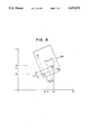
- FIG. 3 is a view showing a drawing placed upon a tablet surface
- FIG. 4A and FIG. 4B are a flowchart of processing according to the present invention.
- FIG. 5 is a view for describing the present invention.
- FIG. 6 is a view for describing a conventional method of setting a coordinate system.
- FIG. 1 is a block diagram of an NC unit having an automatic programming function for realizing the present invention.
- Numeral 1 denotes a processor, 2 a ROM, 3 a RAM for storing defined figure elements as well as the results of processing, 4 an NC data memory for storing created NC data, 5 a keyboard, 6 a disk controller, FL a floppy, 7 a graphic display unit (CRT), and 8 a tablet device.
- numeral 8a denotes a tablet surface
- 8b a menu chart
- 8c a tablet sensing area
- 8d a tablet cursor.
- the menu chart 8b is affixed to the tablet surface 8a.
- the tablet cursor 8d By using the tablet cursor 8d to select prescribed items written on the menu chart 8b, various items and data can be entered. Further, by moving the tablet cursor 8d on the tablet sensing area 8c and picking a desired point, the selected position can be entered in the tablet coordinate system.
- FIG. 2 is a view for describing the principal portions of the menu chart 108b, in which numeral 11 denotes an "EXECUTE” section, 12 a “POINT DEFINITION” section, 13 a “STRAIGHT-LINE DEFINITION” section, and 14 a "CIRCLE DEFINITION” section.
- CCT in the "EXECUTE” section 11 represents a "COORDINATE SYSTEM SETTING" item.
- FIG. 3 is a view showing a drawing DRW of the figure FIG of a manufactured part, which is drawn free hand, placed on the tablet sensing area 8c of the tablet device 8.
- FIG. 4 is a flowchart of processing for setting a drawing coordinate system and scale according to the present invention
- FIG. 5 is a view for describing the flowchart.
- the method of the invention for setting the drawing coordinate system and scale will now be described on the assumption that the drawing DRW (FIG. 3) has been placed upon the tablet sensing area 8c. It is assumed that a system program for executing drawing coordinate systems and scale processing has been stored in the RAM 3 from the floppy FL in advance, and that the drawing coordinate system to be set is a standard coordinate system (right-hand rectangular coordinate system).
- the operator selects the "COORDINATE SETTING" item CCT from the menu chart 8b shown in FIG. 2 (step 101).
- a message for specifying two points of known coordinates in the drawing coordinate system is displayed on the display screen of the graphic display unit 7. Therefore, in response to the message, the operator uses the tablet cursor 8d to select two points P 1 , P 2 (see FIG. 5) that are located in the tablet sensing area 8c and whose coordinates is the drawing coordinate system are evident (step 102).
- the processor 1 obtains coordinates (xt 1 ,yt 1 ), (xt 2 ,yt 2 ) of these two points in the tablet coordinate system X T -.Y T , computes a distance LT between these two points in accordance with the following equation: ##EQU2## and stores the distance in the RAM 3 (step 104).
- the operator enters coordinates (xf 1 ,yf 1 ), (xf 2 ,yf 2 ) of the two points P 1 , p 2 in the drawing coordinate system by the keyboard 5 or the like (step 105).
- the processor 1 uses the entered coordinates of the two points P 1 , P 2 in the drawing coordinate system to calculate a distance LF between the two points in the drawing coordinate system in accordance with the following equation (step 106): ##EQU3## compares the distance LF between the two points in the drawing coordinate system and the distance LT between the two points in the tablet coordinate system, obtains the figure scale
- the processor 1 performs processing for setting the drawing coordinate system based on the scale S and the coordinates of the two points P 1 , P 2 . More specifically, the processor obtains a circular arc C 1 (see FIG. 5) whose center is the point P 1 and whose radius is S.
- the reason for specifying the right.hand intersection Q 1 is that the orientation of the X axis of a right.hand rectangular coordinate system is on the right-hand side.
- the processor obtains S ⁇ xf 1 , which is found by multiplying the X component xf 1 of point P 1 in the drawing coordinate system by scale S, and obtains a point P 0 found by offsetting point P 1 leftward by a distance of S ⁇ xf 1 along the line segment P 1 Q 1 (step 111).
- a straight line perpendicular to the line segment P 0 Q 1 at point P 0 is adopted as the Y axis of the drawing coordinate system X D -Y D (step 112).
- the processor then obtains S ⁇ yf 1 , which is found by multiplying the Y component yf 1 of point P 1 in the drawing coordinate system by the scale S, obtains a point O found by offsetting point P 0 downward by a distance of S ⁇ yf 1 along the Y axis of the drawing coordinate system, adopts the point O as the origin of the drawing coordinate system X D -Y D , obtains a straight line perpendicular to the Y axis at point O, and adopts this straight line as the X axis of the drawing coordinate system (step 113).
- the processor 1 obtains a transformation matrix for transforming coordinates in the tablet coordinate system X T -Y T into coordinates in the drawing coordinate system X D -Y D , and stores the matrix in the RAM 3 (step 114).
- the transformation matrix is obtained as follows: Angles of inclination ⁇ T , ⁇ D of the straight line P 1 P 2 in the tablet coordinate system X T -Y T and drawing coordinate system X D -Y D are obtained from the following equations:
- FIG of the manufactured article on the drawing DRW is defined by repeating the processing of obtaining coordinates (x,y) of points on the drawing DRW in the table coordinate system X T -X T and transforming these coordinates into coordinates (x',y') in the drawing coordinate system X D -Y D using the transformation matrix obtained above.
- the present invention is arranged to obtain the coordinates of two points on a figure, the coordinates of which two points are known in a drawing coordinate system, in a tablet coordinate system, calculate the distance between the two points in the tablet coordinate system, calculate the distance between the two points in the drawing coordinate system using keyed.in coordinates of the two points in the drawing coordinate system, obtain a scale of the figure by comparing the distance between the two points in the drawing coordinate system and the distance between the two points in the tablet coordinate system, and set the drawing coordinate system on the drawing based on the scale and the two known points.
Abstract
The invention relates to a method of setting the coordinate system (XD -YD) of a figure drawn on a drawing (DRW) on a tablet surface (8c), and of setting scale. The method includes entering coordinates in a tablet coordinate system (XT -YT) by selecting two points (P1, P2) whose coordinates are known in the drawing coordinate system, calculating the distance between the two points in the tablet coordinate system and the distance between the two points in the drawing coordinate system using the abovementioned coordinates and the known coordinates, and obtaining a scale S of the figure based on a ratio of the distances between the two points in both coordinate systems. The drawing coordinate system (XD -YD) is placed upon the tablet surface based on the scale S and the coordinates of the two points (P1, P2) in each of the coordinate systems.
Description
1. Technical Field
This invention relates to a method of setting a drawing coordinate system and scale. More particularly, the invention relates to a method of setting the coordinate system and scale of a figure drawn on a drawing set upon a tablet.
2. Background Art
There are cases where a drawing as drawn free hand or the shape of a manufactured article on a drawing which does not include dimensions is defined. In such case, the drawing is placed upon a tablet sensing area of a tablet, the tablet device is made to recognize the scale of the drawing or the drawing coordinate system, (the scale or the drawing coordinate system is set), and then a transformation matrix is obtained for transforming the coordinates of the tablet coordinate system into the coordinates of the drawing coordinate system. Thereafter, the coordinates of points on the drawing are found in the tablet coordinate system, and these coordinates are transformed into those in the drawing coordinate system by the aforementioned transformation matrix. This processing is repeated to define the shape of the manufactured article on the drawing.
The method of setting the scale and the drawing coordinate system will be described with reference to FIG. 6. First, the scale is set by directly entering a drawing scale value "S" from a keyboard. Next, one point P on a drawing DW placed upon a tablet is selected and the coordinates (x0,y0) of this point in the drawing coordinate system are entered from the keyboard. After which a point Q on the drawing DW which will render a line segment PQ parallel to or coincident with the X axis of the drawing coordinate system is entered, thereby setting the drawing coordinate system. More specifically, the system uses the initially set scale S to obtain axial distance components S.x0, S y0, in the tablet coordinate system XT.YT, from the point P to the origin O of the drawing coordinate system. The system thereafter point at distances of S.x0, S.y0 from the point P along the respective axes and, regarding this point as being the origin O of the drawing coordinate system, sets the drawing coordinate system on the tablet surface. If S represents the scale, (x0 ',y0 ') the coordinates of the origin O in the tablet coordinate system and θ the angle of inclination between the two coordinate systems, then transformation equations for transforming coordinates (x,y) in the tablet coordinate system into coordinates (x',y') in the drawing coordinate system will be as follows: ##EQU1##
x.sub.0 '=x.sub.1 -(S.x.sub.0. cosθ-y.sub.0.sinθ)(2)
y.sub.0 '=x.sub.1 -(S.x.sub.0. cosθ+y.sub.0.sinθ)(3)
θ=tan.sup.-1 (y.sub.2 -y.sub.1)/x.sub.2 -x.sub.1) (4)
where (x1,y1),(x2,y2) are the coordinates of points P, Q in the tablet coordinate system XT.YT.
However, with the conventional method of setting scale and drawing coordinate system, the setting of scale and the setting of the drawing coordinate system involve two entirely different operations. As a result, the setting procedure is a troublesome one.
In addition, the conventional method cannot be applied unless the X-axis or Y-axis direction on the drawing is already known.
Accordingly, an object of the present invention is to provide a method in which a drawing coordinate system and scale can be set by one and the same operation, and in which the drawing coordinate system and scale can be set without knowing the directions of axes on the drawing.
The present invention provides a method of setting the coordinate system and scale of a figure drawn on a drawing set upon a tablet.
Coordinates (xt1,yt1), (xt2,yt2) in a tablet coordinate system are obtained by selecting two points P1, P2 on a drawing, the coordinates of which points in the drawing coordinate system are already known, and the distance between these two points in the tablet coordinate system is calculated. The distance between the two points in the drawing coordinate system is calculated using coordinates (xf1,yf1), (xf2,yf2) in the drawing coordinate system. A scale S of the drawing is obtained based upon a ratio of the distance between the two points in the drawing coordinate system and the distance between the two points in the tablet coordinate system. The drawing coordinate system is set on the tablet surface based on the scale S and the coordinates of the two point P1, P2 in the drawing coordinate system and in the tablet coordinate system.
FIG. 1 is a block diagram of an NC unit having an automatic programming function for realizing the present invention;
FIG. 2 is a view for describing the principal portions of a menu chart in the present invention;
FIG. 3 is a view showing a drawing placed upon a tablet surface;
FIG. 4A and FIG. 4B are a flowchart of processing according to the present invention;
FIG. 5 is a view for describing the present invention; and
FIG. 6 is a view for describing a conventional method of setting a coordinate system.
FIG. 1 is a block diagram of an NC unit having an automatic programming function for realizing the present invention.
Numeral 1 denotes a processor, 2 a ROM, 3 a RAM for storing defined figure elements as well as the results of processing, 4 an NC data memory for storing created NC data, 5 a keyboard, 6 a disk controller, FL a floppy, 7 a graphic display unit (CRT), and 8 a tablet device.
In the tablet device 8, numeral 8a denotes a tablet surface, 8b a menu chart, 8c a tablet sensing area, and 8d a tablet cursor. The menu chart 8b is affixed to the tablet surface 8a. By using the tablet cursor 8d to select prescribed items written on the menu chart 8b, various items and data can be entered. Further, by moving the tablet cursor 8d on the tablet sensing area 8c and picking a desired point, the selected position can be entered in the tablet coordinate system.
FIG. 2 is a view for describing the principal portions of the menu chart 108b, in which numeral 11 denotes an "EXECUTE" section, 12 a "POINT DEFINITION" section, 13 a "STRAIGHT-LINE DEFINITION" section, and 14 a "CIRCLE DEFINITION" section. CCT in the "EXECUTE" section 11 represents a "COORDINATE SYSTEM SETTING" item.
FIG. 3 is a view showing a drawing DRW of the figure FIG of a manufactured part, which is drawn free hand, placed on the tablet sensing area 8c of the tablet device 8.
FIG. 4 is a flowchart of processing for setting a drawing coordinate system and scale according to the present invention, and FIG. 5 is a view for describing the flowchart. The method of the invention for setting the drawing coordinate system and scale will now be described on the assumption that the drawing DRW (FIG. 3) has been placed upon the tablet sensing area 8c. It is assumed that a system program for executing drawing coordinate systems and scale processing has been stored in the RAM 3 from the floppy FL in advance, and that the drawing coordinate system to be set is a standard coordinate system (right-hand rectangular coordinate system).
First, using the tablet cursor 8d, the operator selects the "COORDINATE SETTING" item CCT from the menu chart 8b shown in FIG. 2 (step 101). As a result, a message for specifying two points of known coordinates in the drawing coordinate system is displayed on the display screen of the graphic display unit 7. Therefore, in response to the message, the operator uses the tablet cursor 8d to select two points P1, P2 (see FIG. 5) that are located in the tablet sensing area 8c and whose coordinates is the drawing coordinate system are evident (step 102).
When the points P1, P2 have been chosen, the processor 1 obtains coordinates (xt1,yt1), (xt2,yt2) of these two points in the tablet coordinate system XT -.YT, computes a distance LT between these two points in accordance with the following equation: ##EQU2## and stores the distance in the RAM 3 (step 104).
Next, the operator enters coordinates (xf1,yf1), (xf2,yf2) of the two points P1, p2 in the drawing coordinate system by the keyboard 5 or the like (step 105). As a result, the processor 1 uses the entered coordinates of the two points P1, P2 in the drawing coordinate system to calculate a distance LF between the two points in the drawing coordinate system in accordance with the following equation (step 106): ##EQU3## compares the distance LF between the two points in the drawing coordinate system and the distance LT between the two points in the tablet coordinate system, obtains the figure scale
S=LT/LF
and stores the scale in the RAM 3 (step 107).
When the scale S has been obtained, the processor 1 performs processing for setting the drawing coordinate system based on the scale S and the coordinates of the two points P1, P2. More specifically, the processor obtains a circular arc C1 (see FIG. 5) whose center is the point P1 and whose radius is S.|xf2 -xf1 | (step 108), a circular arc C2 whose center is the point P2 and whose radius is S.|yf2 -yf1 | (step 109), and a point of intersection Q1, which is the right-hand intersection of two points of intersection Q1, Q2 between the circular arcs C1, C2 (step 110). The reason for specifying the right.hand intersection Q1 is that the orientation of the X axis of a right.hand rectangular coordinate system is on the right-hand side.
Next, the processor obtains S·xf1, which is found by multiplying the X component xf1 of point P1 in the drawing coordinate system by scale S, and obtains a point P0 found by offsetting point P1 leftward by a distance of S·xf1 along the line segment P1 Q1 (step 111). A straight line perpendicular to the line segment P0 Q1 at point P0 is adopted as the Y axis of the drawing coordinate system XD -YD (step 112).
The processor then obtains S·yf1, which is found by multiplying the Y component yf1 of point P1 in the drawing coordinate system by the scale S, obtains a point O found by offsetting point P0 downward by a distance of S·yf1 along the Y axis of the drawing coordinate system, adopts the point O as the origin of the drawing coordinate system XD -YD, obtains a straight line perpendicular to the Y axis at point O, and adopts this straight line as the X axis of the drawing coordinate system (step 113).
When the drawing coordinate system has been set, the processor 1 obtains a transformation matrix for transforming coordinates in the tablet coordinate system XT -YT into coordinates in the drawing coordinate system XD -YD, and stores the matrix in the RAM 3 (step 114). The transformation matrix is obtained as follows: Angles of inclination θT, θD of the straight line P1 P2 in the tablet coordinate system XT -YT and drawing coordinate system XD -YD are obtained from the following equations:
θ.sub.T =tan.sup.-1 (yt.sub.2 -yt.sub.1)/(xt.sub.2 -xt.sub.1)
θ.sub.D =tan.sup.-1 (yf.sub.2 -yf.sub.1)/(xf.sub.2 -xf.sub.1)
and the angle of inclination θ of the drawing coordinate system with respect to the tablet coordinate system is obtained from the following equation:
θ=θ.sub.T-θ.sub.D
Accordingly, transformation equations for transforming coordinates (x,y) in the tablet coordinate system into coordinates (x,,y,) in the drawing coordinate system are as follows: ##EQU4##
X.sub.0 '=xt.sub.1 -(S·xf.sub.1 ·cosθ-S·yf.sub.1 ·sinθ)
Y.sub.0 '=xt.sub.1 -(S·yf.sub.1 ·cosθ-S·xf.sub.1 ·sinθ)
Next, the scale S (e.g., S=0.5) and the drawing coordinate system XD -YD are displayed on the display screen (step 115; see 7b in FIG. 1) and the processing for setting the drawing coordinate system and scale is terminated.
Thereafter, the figure FIG of the manufactured article on the drawing DRW is defined by repeating the processing of obtaining coordinates (x,y) of points on the drawing DRW in the table coordinate system XT -XT and transforming these coordinates into coordinates (x',y') in the drawing coordinate system XD -YD using the transformation matrix obtained above.
Thus, in accordance with the present invention, it is arranged to obtain the coordinates of two points on a figure, the coordinates of which two points are known in a drawing coordinate system, in a tablet coordinate system, calculate the distance between the two points in the tablet coordinate system, calculate the distance between the two points in the drawing coordinate system using keyed.in coordinates of the two points in the drawing coordinate system, obtain a scale of the figure by comparing the distance between the two points in the drawing coordinate system and the distance between the two points in the tablet coordinate system, and set the drawing coordinate system on the drawing based on the scale and the two known points. This makes it possible to define the shape of a manufactured article easily and quickly, as a result of which NC data obtained based upon shape definition data can also be created easily and quickly.
Claims (2)
1. A drawing coordinate system and scale setting method for automatically setting in a tablet device a drawing coordinate system and a scale S of a figure drawn on a drawing placed on a tablet surface having a tablet coordinate system comprising the steps of:
(a) obtaining coordinates (xt1, yt1), (xt2,yt2) in the tablet coordinate system by touching two points P1 and P2 on the figure;
(b) calculating a distance between said two points in the tablet coordinate system;
(c) inputting coordinates (xf1,yf1), (xf2,yf2) of said two points P1,P2 from the drawing coordinate system;
(d) calculating a distance between said two points in the drawing coordinate system using the coordinates of said two points P1, P2 in the drawing coordinate system;
(e) obtaining the scale S of the figure by using the distance between said two points in the drawing coordinate system and the distance between said two points in the tablet coordinate system;
(f) obtaining in the table coordinate system a line segment P1,O1 being parallel to an X axis of the drawing coordinate system, where O1 represents a point of intersection between a circle whose center is the point P1 and whose radius is S * |xf2 -xf1 |, and a circle whose center is the point P2 and whose radius is S * |yf2 -yf1 |;
(g) setting in the tablet device coordinates defining a straight line as a Y axis of the drawing coordinate system, which is perpendicular to the line segment P1 O1 passing through a point P0 that is on an extension of line segment P1 O1 and located at a distance of S * xf1 from the point P1 ; and
(h) setting in the tablet device coordinates defining a point as an origin of the drawing coordinate system which is on the Y axis at a distance of S * yf1 from the point P0
(i) displaying the drawing coordinate system.
2. A drawing coordinate system and scale setting method according to claim 1, further comprising the steps of:
determining an inclination (74 (angle) between the tablet coordinate system and the drawing coordinate system;
obtaining a transformation matrix, which is for transforming coordinates in the tablet coordinate system into coordinates in the drawing coordinate system, by using the scale S, said inclination θ, and coordinates of the point P1 in both of the coordinate systems;
obtaining said coordinates of points on the drawing in the tablet coordinate system; and
transforming said coordinates of the tablet coordinate system into said coordinates in the drawing coordinate system by said transformation matrix.
Applications Claiming Priority (2)
| Application Number | Priority Date | Filing Date | Title |
|---|---|---|---|
| JP63-174922 | 1988-07-15 | ||
| JP63174922A JPH0225977A (en) | 1988-07-15 | 1988-07-15 | Drawing coordinate system and scale setting method |
Publications (1)
| Publication Number | Publication Date |
|---|---|
| US5075873A true US5075873A (en) | 1991-12-24 |
Family
ID=15987061
Family Applications (1)
| Application Number | Title | Priority Date | Filing Date |
|---|---|---|---|
| US07/465,218 Expired - Fee Related US5075873A (en) | 1988-07-15 | 1989-07-05 | Drawing coordinate system and scale setting method |
Country Status (4)
| Country | Link |
|---|---|
| US (1) | US5075873A (en) |
| EP (1) | EP0386252A4 (en) |
| JP (1) | JPH0225977A (en) |
| WO (1) | WO1990000778A1 (en) |
Cited By (10)
| Publication number | Priority date | Publication date | Assignee | Title |
|---|---|---|---|---|
| US5307455A (en) * | 1990-04-11 | 1994-04-26 | Hewlett Packard Company | Display of multiple variable relationships |
| US5317680A (en) * | 1990-06-22 | 1994-05-31 | Broderbund Software, Inc. | Using regular graphic shapes to identify a pointer-selected graphic object |
| US5463731A (en) * | 1990-06-27 | 1995-10-31 | Telefonaktiebolaget L M Ericsson | Monitor screen graphic value indicator system |
| US5491779A (en) * | 1992-04-03 | 1996-02-13 | Bezjian; Richard D. | Three dimensional presentation of multiple data sets in unitary format with pie charts |
| US5526520A (en) * | 1993-09-21 | 1996-06-11 | Krause; Gary M. | Method to organize and manipulate blueprint documents using hypermedia links from a primary document to recall related secondary documents |
| US5602453A (en) * | 1992-02-27 | 1997-02-11 | Mitsubishi Denki Kabushiki Kaisha | Coordinate system display guide for a numerical control apparatus |
| US5712656A (en) * | 1994-08-08 | 1998-01-27 | Sharp Kabushiki Kaisha | Graphic drawing apparatus |
| US5847972A (en) * | 1993-09-24 | 1998-12-08 | Eick; Stephen Gregory | Method and apparatus for graphically analzying a log-file |
| US5850210A (en) * | 1996-09-30 | 1998-12-15 | Wu; Yongan | Display pointing device provided for correlating display cursor locations to physical locations pointed by the display pointing device |
| US5950206A (en) * | 1997-04-23 | 1999-09-07 | Krause; Gary Matthew | Method and apparatus for searching and tracking construction projects in a document information database |
Families Citing this family (5)
| Publication number | Priority date | Publication date | Assignee | Title |
|---|---|---|---|---|
| JPH0618250A (en) * | 1992-04-08 | 1994-01-25 | Sharp Corp | Electronic measure |
| CN1094829A (en) * | 1993-05-04 | 1994-11-09 | 王向阳 | Multi-pen interactive computer graph design method and device |
| JP4053642B2 (en) * | 1998-01-12 | 2008-02-27 | 株式会社ミツトヨ | Coordinate system setting method and image measuring apparatus |
| ITCO20110035A1 (en) * | 2011-09-05 | 2013-03-06 | Xorovo Srl | METHOD OF ADDING AN IMAGE OF AN OBJECT TO AN IMAGE OF A BACKGROUND AND ITS ELECTRONIC DEVICE |
| JP7088181B2 (en) | 2017-05-29 | 2022-06-21 | 東洋紡株式会社 | Clothing for measuring biological information |
Citations (1)
| Publication number | Priority date | Publication date | Assignee | Title |
|---|---|---|---|---|
| US4577214A (en) * | 1981-05-06 | 1986-03-18 | At&T Bell Laboratories | Low-inductance power/ground distribution in a package for a semiconductor chip |
Family Cites Families (7)
| Publication number | Priority date | Publication date | Assignee | Title |
|---|---|---|---|---|
| JPS58149577A (en) * | 1982-02-27 | 1983-09-05 | Fanuc Ltd | Setting system of coordinate system |
| JPS59114609A (en) * | 1982-12-22 | 1984-07-02 | Hitachi Ltd | Method and device for controlling robot |
| JPS60204006A (en) * | 1984-03-27 | 1985-10-15 | Seiko Epson Corp | Control device of robot |
| JPS61109175A (en) * | 1984-10-31 | 1986-05-27 | Mitsubishi Electric Corp | Electronic file device for drawing |
| US4710758A (en) * | 1985-04-26 | 1987-12-01 | Westinghouse Electric Corp. | Automatic touch screen calibration method |
| JPS62278679A (en) * | 1986-05-27 | 1987-12-03 | Tokyo Gas Co Ltd | Graphic processing mechanism |
| JPS63104105A (en) * | 1986-10-22 | 1988-05-09 | Aisin Seiki Co Ltd | Conversion method for robot visual coordinate system |
-
1988
- 1988-07-15 JP JP63174922A patent/JPH0225977A/en active Pending
-
1989
- 1989-07-05 WO PCT/JP1989/000676 patent/WO1990000778A1/en not_active Application Discontinuation
- 1989-07-05 US US07/465,218 patent/US5075873A/en not_active Expired - Fee Related
- 1989-07-05 EP EP19890908276 patent/EP0386252A4/en not_active Withdrawn
Patent Citations (1)
| Publication number | Priority date | Publication date | Assignee | Title |
|---|---|---|---|---|
| US4577214A (en) * | 1981-05-06 | 1986-03-18 | At&T Bell Laboratories | Low-inductance power/ground distribution in a package for a semiconductor chip |
Non-Patent Citations (8)
| Title |
|---|
| English Abs of Japanese A 59 114609, Jul. 2, 84. * |
| English Abs of Japanese A-59 114609, Jul. 2, 84. |
| English Abs. of Japanese A 60 204006, Oct. 15, 85. * |
| English Abs. of Japanese A 61108175, May 27, 86. * |
| English Abs. of Japanese A 62278679, Dec. 3, 87. * |
| English Abs. of Japanese A 63104105, May 8, 88. * |
| English Abs. of Japanese A-60 204006, Oct. 15, 85. |
| English Abs. of Japanese A-63104105, May 8, 88. |
Cited By (10)
| Publication number | Priority date | Publication date | Assignee | Title |
|---|---|---|---|---|
| US5307455A (en) * | 1990-04-11 | 1994-04-26 | Hewlett Packard Company | Display of multiple variable relationships |
| US5317680A (en) * | 1990-06-22 | 1994-05-31 | Broderbund Software, Inc. | Using regular graphic shapes to identify a pointer-selected graphic object |
| US5463731A (en) * | 1990-06-27 | 1995-10-31 | Telefonaktiebolaget L M Ericsson | Monitor screen graphic value indicator system |
| US5602453A (en) * | 1992-02-27 | 1997-02-11 | Mitsubishi Denki Kabushiki Kaisha | Coordinate system display guide for a numerical control apparatus |
| US5491779A (en) * | 1992-04-03 | 1996-02-13 | Bezjian; Richard D. | Three dimensional presentation of multiple data sets in unitary format with pie charts |
| US5526520A (en) * | 1993-09-21 | 1996-06-11 | Krause; Gary M. | Method to organize and manipulate blueprint documents using hypermedia links from a primary document to recall related secondary documents |
| US5847972A (en) * | 1993-09-24 | 1998-12-08 | Eick; Stephen Gregory | Method and apparatus for graphically analzying a log-file |
| US5712656A (en) * | 1994-08-08 | 1998-01-27 | Sharp Kabushiki Kaisha | Graphic drawing apparatus |
| US5850210A (en) * | 1996-09-30 | 1998-12-15 | Wu; Yongan | Display pointing device provided for correlating display cursor locations to physical locations pointed by the display pointing device |
| US5950206A (en) * | 1997-04-23 | 1999-09-07 | Krause; Gary Matthew | Method and apparatus for searching and tracking construction projects in a document information database |
Also Published As
| Publication number | Publication date |
|---|---|
| EP0386252A1 (en) | 1990-09-12 |
| EP0386252A4 (en) | 1992-08-12 |
| JPH0225977A (en) | 1990-01-29 |
| WO1990000778A1 (en) | 1990-01-25 |
Similar Documents
| Publication | Publication Date | Title |
|---|---|---|
| US5075873A (en) | Drawing coordinate system and scale setting method | |
| US7812841B2 (en) | Display controlling apparatus, information terminal unit provided with display controlling apparatus, and viewpoint location controlling apparatus | |
| US4786897A (en) | Display screen control method | |
| US5565887A (en) | Method and apparatus for moving a cursor on a computer screen | |
| US6014127A (en) | Cursor positioning method | |
| EP2278797A2 (en) | Method and apparatus for selecting items in an on-screen menu | |
| US6057827A (en) | Automatic pointer positioning for 3D computer modeling | |
| US5471569A (en) | Retrieval space determination system for three-dimensionally shaped parts in a CAD system | |
| US6542148B1 (en) | Cursor display device for use with a multi-display system | |
| JP3128415B2 (en) | Cursor control method | |
| JP3361652B2 (en) | 3D figure arrangement input method and graphic system | |
| JPH0512208A (en) | Command input system | |
| JPH04180180A (en) | Three-dimensional position input method and device | |
| JPH0683540A (en) | Cursor position designating method | |
| JP2751114B2 (en) | Character processing method | |
| JP4386527B2 (en) | Drawing support method and medium storing CAD program | |
| JP3691105B2 (en) | 3D image processing system | |
| JPH0981784A (en) | Three-dimensional object selection device | |
| JP2004259024A (en) | Operation simulation device | |
| JPH06119430A (en) | Graphic display device | |
| KR0160739B1 (en) | Mage display method | |
| US5444831A (en) | Developed product shape deciding method for a computer-aided design system | |
| JP2664903B2 (en) | Graphic system | |
| JP3381994B2 (en) | Display screen switching device | |
| JP2003178330A (en) | Three-dimensional solid arrangement editing method and three-dimensional solid arrangement editing device |
Legal Events
| Date | Code | Title | Description |
|---|---|---|---|
| AS | Assignment |
Owner name: FANUC LTD, JAPAN Free format text: ASSIGNMENT OF ASSIGNORS INTEREST.;ASSIGNORS:SEKI, MASAKI;TAKEGAHARA, TAKASHI;KAJITANI, AKIRA;REEL/FRAME:005462/0055 Effective date: 19900316 |
|
| FEPP | Fee payment procedure |
Free format text: PAYOR NUMBER ASSIGNED (ORIGINAL EVENT CODE: ASPN); ENTITY STATUS OF PATENT OWNER: LARGE ENTITY |
|
| CC | Certificate of correction | ||
| FPAY | Fee payment |
Year of fee payment: 4 |
|
| REMI | Maintenance fee reminder mailed | ||
| LAPS | Lapse for failure to pay maintenance fees | ||
| FP | Lapsed due to failure to pay maintenance fee |
Effective date: 19991224 |
|
| STCH | Information on status: patent discontinuation |
Free format text: PATENT EXPIRED DUE TO NONPAYMENT OF MAINTENANCE FEES UNDER 37 CFR 1.362 |