US5084151A - Method and apparatus for forming prosthetic device having a biocompatible carbon film thereon - Google Patents
Method and apparatus for forming prosthetic device having a biocompatible carbon film thereon Download PDFInfo
- Publication number
- US5084151A US5084151A US07/480,094 US48009490A US5084151A US 5084151 A US5084151 A US 5084151A US 48009490 A US48009490 A US 48009490A US 5084151 A US5084151 A US 5084151A
- Authority
- US
- United States
- Prior art keywords
- carbon
- substrate
- cathode
- chamber
- sputtered
- Prior art date
- Legal status (The legal status is an assumption and is not a legal conclusion. Google has not performed a legal analysis and makes no representation as to the accuracy of the status listed.)
- Expired - Lifetime
Links
Images


Classifications
-
- A—HUMAN NECESSITIES
- A61—MEDICAL OR VETERINARY SCIENCE; HYGIENE
- A61F—FILTERS IMPLANTABLE INTO BLOOD VESSELS; PROSTHESES; DEVICES PROVIDING PATENCY TO, OR PREVENTING COLLAPSING OF, TUBULAR STRUCTURES OF THE BODY, e.g. STENTS; ORTHOPAEDIC, NURSING OR CONTRACEPTIVE DEVICES; FOMENTATION; TREATMENT OR PROTECTION OF EYES OR EARS; BANDAGES, DRESSINGS OR ABSORBENT PADS; FIRST-AID KITS
- A61F2/00—Filters implantable into blood vessels; Prostheses, i.e. artificial substitutes or replacements for parts of the body; Appliances for connecting them with the body; Devices providing patency to, or preventing collapsing of, tubular structures of the body, e.g. stents
- A61F2/02—Prostheses implantable into the body
- A61F2/30—Joints
- A61F2/30767—Special external or bone-contacting surface, e.g. coating for improving bone ingrowth
-
- C—CHEMISTRY; METALLURGY
- C23—COATING METALLIC MATERIAL; COATING MATERIAL WITH METALLIC MATERIAL; CHEMICAL SURFACE TREATMENT; DIFFUSION TREATMENT OF METALLIC MATERIAL; COATING BY VACUUM EVAPORATION, BY SPUTTERING, BY ION IMPLANTATION OR BY CHEMICAL VAPOUR DEPOSITION, IN GENERAL; INHIBITING CORROSION OF METALLIC MATERIAL OR INCRUSTATION IN GENERAL
- C23C—COATING METALLIC MATERIAL; COATING MATERIAL WITH METALLIC MATERIAL; SURFACE TREATMENT OF METALLIC MATERIAL BY DIFFUSION INTO THE SURFACE, BY CHEMICAL CONVERSION OR SUBSTITUTION; COATING BY VACUUM EVAPORATION, BY SPUTTERING, BY ION IMPLANTATION OR BY CHEMICAL VAPOUR DEPOSITION, IN GENERAL
- C23C14/00—Coating by vacuum evaporation, by sputtering or by ion implantation of the coating forming material
- C23C14/06—Coating by vacuum evaporation, by sputtering or by ion implantation of the coating forming material characterised by the coating material
- C23C14/0605—Carbon
-
- C—CHEMISTRY; METALLURGY
- C23—COATING METALLIC MATERIAL; COATING MATERIAL WITH METALLIC MATERIAL; CHEMICAL SURFACE TREATMENT; DIFFUSION TREATMENT OF METALLIC MATERIAL; COATING BY VACUUM EVAPORATION, BY SPUTTERING, BY ION IMPLANTATION OR BY CHEMICAL VAPOUR DEPOSITION, IN GENERAL; INHIBITING CORROSION OF METALLIC MATERIAL OR INCRUSTATION IN GENERAL
- C23C—COATING METALLIC MATERIAL; COATING MATERIAL WITH METALLIC MATERIAL; SURFACE TREATMENT OF METALLIC MATERIAL BY DIFFUSION INTO THE SURFACE, BY CHEMICAL CONVERSION OR SUBSTITUTION; COATING BY VACUUM EVAPORATION, BY SPUTTERING, BY ION IMPLANTATION OR BY CHEMICAL VAPOUR DEPOSITION, IN GENERAL
- C23C14/00—Coating by vacuum evaporation, by sputtering or by ion implantation of the coating forming material
- C23C14/06—Coating by vacuum evaporation, by sputtering or by ion implantation of the coating forming material characterised by the coating material
- C23C14/14—Metallic material, boron or silicon
- C23C14/20—Metallic material, boron or silicon on organic substrates
- C23C14/205—Metallic material, boron or silicon on organic substrates by cathodic sputtering
-
- C—CHEMISTRY; METALLURGY
- C23—COATING METALLIC MATERIAL; COATING MATERIAL WITH METALLIC MATERIAL; CHEMICAL SURFACE TREATMENT; DIFFUSION TREATMENT OF METALLIC MATERIAL; COATING BY VACUUM EVAPORATION, BY SPUTTERING, BY ION IMPLANTATION OR BY CHEMICAL VAPOUR DEPOSITION, IN GENERAL; INHIBITING CORROSION OF METALLIC MATERIAL OR INCRUSTATION IN GENERAL
- C23C—COATING METALLIC MATERIAL; COATING MATERIAL WITH METALLIC MATERIAL; SURFACE TREATMENT OF METALLIC MATERIAL BY DIFFUSION INTO THE SURFACE, BY CHEMICAL CONVERSION OR SUBSTITUTION; COATING BY VACUUM EVAPORATION, BY SPUTTERING, BY ION IMPLANTATION OR BY CHEMICAL VAPOUR DEPOSITION, IN GENERAL
- C23C14/00—Coating by vacuum evaporation, by sputtering or by ion implantation of the coating forming material
- C23C14/22—Coating by vacuum evaporation, by sputtering or by ion implantation of the coating forming material characterised by the process of coating
- C23C14/34—Sputtering
- C23C14/35—Sputtering by application of a magnetic field, e.g. magnetron sputtering
- C23C14/354—Introduction of auxiliary energy into the plasma
- C23C14/355—Introduction of auxiliary energy into the plasma using electrons, e.g. triode sputtering
-
- A—HUMAN NECESSITIES
- A61—MEDICAL OR VETERINARY SCIENCE; HYGIENE
- A61F—FILTERS IMPLANTABLE INTO BLOOD VESSELS; PROSTHESES; DEVICES PROVIDING PATENCY TO, OR PREVENTING COLLAPSING OF, TUBULAR STRUCTURES OF THE BODY, e.g. STENTS; ORTHOPAEDIC, NURSING OR CONTRACEPTIVE DEVICES; FOMENTATION; TREATMENT OR PROTECTION OF EYES OR EARS; BANDAGES, DRESSINGS OR ABSORBENT PADS; FIRST-AID KITS
- A61F2/00—Filters implantable into blood vessels; Prostheses, i.e. artificial substitutes or replacements for parts of the body; Appliances for connecting them with the body; Devices providing patency to, or preventing collapsing of, tubular structures of the body, e.g. stents
- A61F2/02—Prostheses implantable into the body
- A61F2/30—Joints
- A61F2/3094—Designing or manufacturing processes
-
- A—HUMAN NECESSITIES
- A61—MEDICAL OR VETERINARY SCIENCE; HYGIENE
- A61F—FILTERS IMPLANTABLE INTO BLOOD VESSELS; PROSTHESES; DEVICES PROVIDING PATENCY TO, OR PREVENTING COLLAPSING OF, TUBULAR STRUCTURES OF THE BODY, e.g. STENTS; ORTHOPAEDIC, NURSING OR CONTRACEPTIVE DEVICES; FOMENTATION; TREATMENT OR PROTECTION OF EYES OR EARS; BANDAGES, DRESSINGS OR ABSORBENT PADS; FIRST-AID KITS
- A61F2310/00—Prostheses classified in A61F2/28 or A61F2/30 - A61F2/44 being constructed from or coated with a particular material
- A61F2310/00389—The prosthesis being coated or covered with a particular material
- A61F2310/00574—Coating or prosthesis-covering structure made of carbon, e.g. of pyrocarbon
Definitions
- the invention relates to a prosthetic device having a thin continuous biocompatible film of carbon firmly adherent to a substrate, and to a method of and apparatus for forming the prosthetic device.
- Representative of the prior art techniques for coating a carbon film on a substrate of a prosthetic device include chemical vapor deposition, thermal evaporation by means of an electron beam and ion plating.
- the deposited carbon is not biocompatible and does not firmly adhere to the substrate.
- the carbon on the substrate is in form of graphite which has been found not to be biocompatible.
- the deposited carbon tends to separate and is removed from the substrate during use causing body fluids and tissue to attack and degrade the prosthetic device.
- the ion plating technique is a modification of vacuum evaporation in which the substrate is held during the deposition at a high negative potential so that it is bombarded by positive ions, in order to improve the adhesion and the structural properties of the film.
- this technique cannot be advantageously employed with electrically insulated substrates, like polymers.
- non-conductive desirable substrates such as DACRON (a polyester resin), TEFLON (polytetrafluoroethylene) and other relatively low melting polymers.
- a new and unique prosthetic device which includes a biocompatible carbon film firmly adherent to a substrate.
- the carbon preferably is turbostratic and is preferably very thin, e.g., less than about one micron.
- the thin carbon biocompatible film is dense and covers at least that portion of the substrate which will be in contact with body tissue and/or fluids to insure against physiological rejection and degradation of the prosthetic device.
- the carbon can be deposited on a variety of substrates, including low temperature substrates, in situ, without adversely affecting the mechanical properties of the substrate.
- the preferred substrates include fabrics of medical grade DACRON and TEFLON which have relatively low softening points, and non-refractory metals, such as Haynes 25 alloy.
- the prosthetic devices of the present invention include valves, particularly cardiac valves, grafts and patches, including vascular grafts, tubular prostheses, sutures, catheters, otologic prostheses, tendon and ligament prostheses, dental implants, jaw replacements and other prosthetic devices for the repair or replacement of bones and joints.
- valves particularly cardiac valves, grafts and patches, including vascular grafts, tubular prostheses, sutures, catheters, otologic prostheses, tendon and ligament prostheses, dental implants, jaw replacements and other prosthetic devices for the repair or replacement of bones and joints.
- a new and unique method of and apparatus for forming the prosthetic devices of the present invention wherein the carbon is deposited on the substrate, in situ, at a low temperature and pressure and in a manner which enhances the adhesion of the carbon and does nor adversely affect the properties of the substrate.
- the prosthetic devices of the invention are formed by triode sputtering vacuum deposition which achieves the desired results with respect to the carbon and the substrate and the required adherence therebetween.
- triode sputtering vacuum deposition of the present invention there is provided an upper and remote ionization chamber for generating a plasma beam of an inert gas containing positively charged ions of high energy, a lower sputtering chamber, including a carbon source (target) spaced from the ionization chamber which is negatively charged and surrounded by an anode, an intermediate magnetic coil about the sputtering chamber for collimating the plasma beam, and a substrate of the prosthetic device positioned within the sputtering chamber and in proximity to the target for receiving the carbon atoms sputtered from the target by the bombarding ions of the plasma beam.
- target carbon source
- intermediate magnetic coil about the sputtering chamber for collimating the plasma beam
- substrate of the prosthetic device positioned within the sputtering chamber and in proximity to the target for receiving
- the ionization of the inert gas and generation of plasma is achieved in an ionization chamber which is remote from the target. Since the substrate is in relative proximity to the target, and remote from the ionization chamber, the substrate is insulated from the high temperatures used to generate the plasma. Accordingly, the present invention minimizes transfer of heat to the substrate.
- means are provided for cooling the target and the anode which further serves to minimize the transfer of heat to the substrate.
- the present invention employs a high voltage, low current (preferably direct current) to the target (carbon cathode) which further reduces the heat generated in the lower sputtering chamber.
- Another feature of the invention is to operate the sputtering chamber at low pressures so that the force and speed of the sputtered carbon is not deterred by its environment.
- the present invention operates at low temperatures and pressures so that the substrates are not adversely affected and the sputtered carbon firmly adheres thereto.
- Another feature of the present invention is that either graphite or pyrolytic carbon can be used for the target.
- the carbon deposited on the substrate is a biocompatible carbon which is turbostratic in structure.
- the invention produces a thin, uniform, dense film of turbostratic carbon thereon. This is accomplished by movably positioning the substrates within the sputtering chamber to insure uniform deposition of carbon.
- Still another feature of the present invention is that specific temperature gradients can be used at the substrates to improve adherence of the biocompatible carbon being deposited thereon.
- the desired prosthetic device including a biocompatible film of turbostratic carbon of the desired thinness and uniformity, deposited on and firmly adherent to a substrate so that the device has and maintains its integrity.
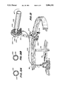
- FIG. 1 is a perspective view of a preferred embodiment of a triode sputtering vacuum deposition apparatus for carrying out the present invention
- FIG. 2 is a perspective view of the triode sputtering vacuum apparatus of FIG. 1 wherein the bell jar (ionization and sputtering chambers) is hydraulically raised from its base to expose the target and surrounding anode;
- FIG. 3 is a top view of the apparatus of FIG. 1, wherein the bell jar has been rotated out of the way for purpose of loading substrates to be coated and for removing coated substrates;
- FIG. 4 is a longitudinal sectional view of the sputtering apparatus of FIGS. 1-3, illustrating the ionization and sputtering chambers, the target and anode, and an internal housing including disks for holding the substrates to be coated;
- FIG. 5 is a perspective view of a lower rotatable ring of the apparatus of FIGS. 1-3, upon which the internal housing is placed, and an upper stationary ring for engaging and causing the disks to rotate about their centers as the housing and disks are rotated by the lower rotatable ring about the longitudinal axis of the bell jar;
- FIG. 6 is a schematic view of the apparatus of FIG. 1 illustrating the electric circuits and heating, cooling, hydraulic and vacuum systems utilized by the invention, along with showing the plasma beam generated in the ionization chamber centered and directed to the target area;
- FIG. 7 is a perspective view of a disk and frame for holding a substrate which is to be coated in accordance with the present invention.
- FIG. 8 is a perspective view of the coated substrate of the invention after it has been removed from the disk and frame shown in FIG. 7;
- FIG. 8A is a cross sectional view of the coated substrate of FIG. 8;
- FIG. 9 is a schematic view of a component for a cardiac valve encased within the coated substrate of FIG. 8;
- FIGS. 10, 11, 11A and 12 are similar to FIGS. 7, 8, 8A and 9, but illustrate the use of a disk and frame (FIG. 10) for coating a masked substrate which allows the substrate to be coated only over selected portions (FIG. 11 and 11A) for use in a ring of a mechanical cardiac valve (FIG. 12);
- FIG. 13 is a perspective view of an apparatus of the invention for coating tubing, e.g., vascular tubing, which can be positioned in the apparatus of FIGS. 1-5;
- tubing e.g., vascular tubing
- FIG. 13A is a cross sectional view of the coated tubing prior to inversion
- FIG. 13B is a cross sectional view of the coated tubing after inversion
- FIG. 14 is a perspective view of another apparatus of the invention for coating suture yarn which also can be positioned in the device of FIGS. 1-5;
- FIG. 15 is an enlarged view of the frame and suture yarn of FIG. 14.
- FIG. 16 is a cross sectional view of the coated yarn.
- FIGS. 1-9 there is shown a triode vacuum apparatus 10 (FIGS. 1-7) for coating a substrate 2 with a thin, uniform, dense coating or film 4 of biocompatible carbon firmly adherent to the substrate 2 (FIGS. 8 and 8A) for use in a prosthetic device 6 (FIG. 9).
- a triode vacuum apparatus 10 for coating a substrate 2 with a thin, uniform, dense coating or film 4 of biocompatible carbon firmly adherent to the substrate 2 (FIGS. 8 and 8A) for use in a prosthetic device 6 (FIG. 9).
- the apparatus 10 (FIGS. 1-6) includes a bell jar 12 mounted on a hydraulically operated telescoping arm 13 for moving the jar 12 to and from a base 14.
- the bell jar 12 has an upper ionization chamber 16 and a lower sputtering chamber 18.
- a target 20 Positioned in the sputtering chamber 18 when the jar 12 is closed (FIGS. 1 and 4) is a target 20 which provides a source for the biocompatible carbon and which is circumscribed by an anode 22.
- a removable support structure or housing 24 for the substrates 2 to be coated by the carbon (FIG. 4).
- This illustrative apparatus is of the general type marketed by Balzers AG of Liechtenstein under Model BB 800 033 PE 7503.
- the ionization chamber 16 generates a plasma beam 28 (FIGS. 1 and 6) of concentrated ionized particles which are drawn to the target 20 for sputtering carbon onto the substrates 2.
- the chamber 16 includes a filament 30 at its upper end, an auxiliary anode 32 at its lower end having a central opening 34 therethrough and an intermediate inlet 36 for an inert gas, such as argon, which forms the plasma beam 28.
- the argon gas flows from a source (FIG.
- a valve controlled conduit 38 connected to the inlet 36 and into the ionization chamber 16, wherein the heated filament 30 ionizes the argon into concentrated positively charged ions which are drawn through the opening 34 of the auxiliary anode 32 into sputtering chamber 18 to the target 20.
- the argon ions are drawn through the sputtering chamber 18 they are collimated into the shape schematically illustrated in FIG. 6 by a magnetic field coil 40 centrally positioned about the outer wall of the sputtering chamber 18.
- gases in the sputtering chamber 18 can be removed by a vacuum pump connected to a vacuum outlet 44 in the base 14 via the valve controlled conduit 46 (FIGS. 3 and 4). Throughout the operation the vacuum pump maintains the sputtering chamber 18 at low pressures so that the environmental effect on the force and speed of the sputtered carbon is minimal.
- the target 20 and the substrates 2 are spaced from the ionization chamber 16. Accordingly the heat generated in forming the plasma beam 28, in substance, does not reach or adversely affect the substrates 2.
- the target 20 and anode 22 are mounted within and on a stand 48 affixed to the base 14 (FIGS. 2, 4 and 6).
- the target 20 is positioned within a cylindrical cavity 50 and is circumscribed by the annular anode 22.
- the target 20 can comprise graphite, pyrolytic carbon or a combination thereof. Surprisingly and unexpectedly in each embodiment the carbon sputtered onto the substrates 2 is in a biocompatible form, namely turbostratic.
- the target 20 is cylindrical and comprises a graphite base 52 upon which is positioned an outer layer 54 of pyrolytic carbon.
- high voltages and low currents are used for the target 20 by the electric source (FIG. 6). Also, the target 20 and anode 22 are water cooled. By so doing, heat from infrared radiation from the target 20 and anode 22 is minimized.
- the relatively high voltages e.g., at least about 500 volts and preferably about 1000 to 3000 volts, provide the energy needed to properly adhere the sputtered carbon to the substrate and a suitable deposition rate, while low direct currents, e.g., about 0.05 to 0.3 amps., minimize infrared and ultraviolet radiation.
- low voltage levels adversely affect the adhesion of the carbon to the substrate without meaningfully changing the generation of infrared radiation and high currents produce infrared and ultraviolet radiation that can adversely affect the substrates 2.
- the internal housing 24 for the substrates 2 Removably and rotatably positioned within the sputtering chamber 18 is the internal housing 24 for the substrates 2 (FIGS. 4 and 5).
- the housing 24 and related structure are designed to facilitate the coating of the substrates 2 with a dense thin film of turbostratic carbon from the sputtered target 20.
- such structure positions the substrates 2 relative to the target 20 and simultaneously rotates such substrates 2 at predetermined rates about their axis and the longitudinal axis of the bell jar 12 to optimize uniform coating thereon.
- the housing 24 is cylindrical and is supported at its lower end on a rotatable cylindrical ring 59 driven by a belt driven roller 60 and supported by idler rollers 62.
- the roller 60 is connected to the upper end of a shaft 64 rotated by a belt 66 which is driven by a motor (not shown).
- the idler rolls 62 are connected to the upper ends of shafts 68 which are connected at their lower ends to the base 14.
- the housing 24 extends upwardly from the lower rotable ring 59, about the target 20 and anode 22 and into the upper portion of the sputtering chamber 18.
- a cylindrical rail 72 is secured to the inner wall of the housing 24 and traverses the openings 70.
- a notch 74 centrally positioned in each opening 70 for allowing access to an annular slot 76 in the rear wall of the rail 72.
- the described structure of the housing 24 is adapted to receive disks 78 which hold the substrates 2.
- Each disk 78 has a shaft 80 centrally connected to its convex rear wall which is removably seated in the notch 74 and adjacent slot 76, and a hanger 82 extending upwardly therefrom to facilitate carrying, holding and storing of the disks 78.
- Each disk 78 also includes a frame 84 on its concave front wall which is secured to the disk 78 by a screw or other means 86 and which is used to hold the substrate 2.
- a separate stationary ring 88 having rods 89 depending therefrom which are connected at their lower ends to the base 14.
- the disks 78 tilt slightly forward with their lower ends frictionally engaging the stationary ring 88.
- the disks 78 simultaneously rotate about their axis and the longitudinal axis of the bell jar 12 for uniform coating of the substrate 2.
- the disks 73 are tilted forwardly toward the target 20 and positioned a predetermined distance therefrom to optimize uniform coating of the sputtered carbon onto the rotating substrates 2.
- the disks 78 can be used to secure a variety of substrates 2. Referring to FIGS. 7 through 9 a rectangular shaped substrate 2 is secured in a correspondingly shaped frame 84 on a disk 78 by screws or other means 94. After forming the biocompatible carbon film 4 on the substrate 2 in accordance with the present invention, the coated substrate 2 is removed from the frame 84 and can be wrapped around and secured to a stent of a cardiac valve, for example, to form the prosthetic device 6 shown in FIG. 9. In doing so, biocompatible carbon coated sutures, which are preferably also prepared in accordance with the present invention as hereinafter more particularly described, can be used.
- Certain prosthetic devices require only portions of the substrate to be coated with a biocompatible carbon film.
- cardiac valves may have only a portion of the valve exposed to physiological fluids, or it may be desirable to have portions of the prosthetic device attached by tissues after implantation. Those portions not exposed to tissues and fluids or portions which are desirably attached to tissues are masked prior to coating. In such instance the triode sputtering vacuum process of the invention will provide a carbon film only on the unmasked portions. More specifically, and as shown in FIG. 10, the frame 84 has masking segments 98 overlaying the substrate 2. As a result, the present invention will provide a substrate 2 including coated and uncoated portions 99 and 100 (FIGS. 11 and 11A) which can be used to form a ring 101 (FIG. 12) for a cardiac valve comprising a substrate 2 having coated and uncoated regions 99 and 100, respectively.
- the present invention can be used for producing grafts and patches, tubular prostheses, sutures, catheters, otologic prostheses, tendon and ligament prostheses, dental implants, jaw replacements and other prosthetic devices.
- the prosthetic devices of the invention are especially useful as implants because they are biocompatible with body fluids and tissue.
- the implanted prosthetic devices of the invention resist physiological rejection and degradation.
- the prosthetic device consists of or includes a substrate 2 with a thin, uniform, dense film or coating 4 and 99 of biocompatible carbon adherent thereto. See illustrative FIGS. 8A and 11A.
- the invention is particularly well suited for substrates comprising organic polymers having relatively low softening points.
- the substrates includes DACRON which exhibits a change in elasticity at about 150° C. Therefore, it is preferred when coating DACRON to have the substrate exposed to temperatures no higher than the range of 80°-90° C.
- TEFLON is another suitable material which has low softening point substrate.
- TEFLON can withstand temperatures of about 250° C. before softening. It is preferred to limit the temperature in proximity of a TEFLON substrate to no more than about 160°-180° C.
- low temperature materials which can be used for the substrate include silicone, polyacetal resins (DELRIN), polyurethane, low density polyethylene, and non-refractory metals, such as Haynes 25 cobalt-chromium alloys, titanium and titanium alloys.
- the thickness of the substrates will vary depending on the form of and type of material.
- Substrates in the form of woven or knit fabrics, such as DACRON or TEFLON fabrics used in cardiac valves typically are from about 0.1 to 1.0 mm in thickness, and desirably 0.3 mm.
- the carbon films or coatings of the invention deposited on the described substrates are biocompatible, continuous, uniform, dense and cover at least those portions of the substrates which are in contact with physiological fluids that can degrade uncoated substrates.
- the carbon film preferably is thin within the range of about 0.2 to 0.8 micron. Films having a thickness exceeding the preferred range tend to separate from the substrate and/or take too long to produce. Films below the preferred thickness may not uniformly cover the substrate surface.
- the carbon film of the invention is dense, e.g., 2.2 gm/cm 3 , and preferably is turbostratic because this form of carbon is known to be biocompatible.
- the carbon film of the invention also strongly adheres to the substrate so that the coated substrate is able to repeatedly flex without separation of the film. The adhesion is tested in accordance with the ASTM 03359 standard procedure.
- the process of the invention is admirably suited for forming the described biocompatible film on a wide variety of prosthetic devices consisting of or including coated substrates.
- the following describes the process utilizing the illustrative embodiment of the apparatus 10 for forming the prosthetic device as shown in FIGS. 1 and 8, including low temperature substrates of medical grade DACRON and TEFLON.
- the substrates 2 to be used are rectangular in shape as shown in FIG. 8. Prior to initiating the operational phase of the process, the DACRON substrates are cleansed by a non-corrosive solvent.
- the cleansed substrates 2 are mounted by the frame 84 to the disks 78 (FIG. 9) and the loaded disks 78 are mounted on the rail 72 of the housing 24 (FIGS. 4 and 5). In so doing, the disks 78 tilt forward.
- the bell jar 12 is raised from its base 14 by the hydraulically operated telescoping arm 13 and rotated on such arm 13 away from the base 14 as shown in FIG. 3.
- the housing 24 with the assembled disks 78 are placed on the lower rotatable ring 59 and the lower ends of the tilted disks 78 frictionally engage the stationary rail 88 positioned within the housing 24.
- the bell jar 12 is then rotated over the housing 24 and lowered by the hydraulically operated telescoping arm 13 about the housing 24 and into sealing engagement with the base 14 (FIGS. 2 and 1).
- the sputtering chamber 18 is then evacuated and maintained at low pressure levels (10 -4 mbar-10 -2 mbar and preferably 10 -3 mbar) by a vacuum pump via the outlet 44 and conduit 46. This is done to enhance the adhesion of the sputtered and the deposited carbon on the substrates 2. At such low pressure levels, the sputtered carbon atoms maintain their high energy level.
- the target 20 is cleansed by bombardment of the plasma beam 28, and the bell jar 12 is cleansed by removal of moisture and gaseous impurities.
- the cleansing of the bell jar 12 is accomplished by feeding hot water through the helical conduit 57 about the wall of the sputtering chamber 18 and such chamber 18 is evacuated by a vacuum pump to remove vapors and gases.
- the temperature within the sputtering chamber 18 is maintained at about 80° C. by the use of the electric quartz lamps 55.
- the filament 30 is operated at a current of about 80 to about 90 amperes, and preferably about 85 amperes, and argon gas is fed into the chamber 16 via conduit 38 and inlet 36, whereupon a plasma beam 28 is generated consisting of high energy positively charged ions.
- the plasma beam 28 is drawn from the ionization chamber 16 into the sputtering chamber 18 where it is focused or collimated by the magnetic field coil 40 and directed to the target 20.
- the coil 40 also serves to minimize exposure of the substrate 2 to secondary electrons. For such purposes, the coil 40 is operated at about 12 amperes.
- the high energy argon ions of the plasma beam 28 bombard the target 20 causing carbon atoms to separate from the surface of the graphitic or pyrolytic target and flow in the acute angular direction schematically shown in FIG. 4 at substantial speeds onto the substrates 2.
- the substrates 2 are rotated about the longitudinal axis of the bell jar 12 and about their own axis to enhance uniform deposition of carbon.
- rotation about the jar 12 is at the rate of about 4 to 5 revolutions per minute while the disks 59 rotate about 2 revolutions about their axis for each revolution about the jar 12.
- the target 20 is maintained at high voltages and low direct currents, such as 3000 volts and 0.3 amps, by the electric source.
- the high voltages help generate a suitable number of sputtered carbon atoms of the desired high energy while the low currents minimize the generation of infrared and ultraviolet radiation.
- the anode 22 and target 20 are cooled by water flowing at about 20° C. through their respective conduits 56 and 58 to minimize the generation of heat.
- the ionization chamber 16 is at the upper end of the sputtering chamber 18 and spaced a considerable distance from the substrate 2. In this illustrative example, the ionization chamber 16 is about 25 cm from the substrates 2.
- the described process is continued until the carbon film 4 uniformly deposited on the DACRON substrates is about 0.3 microns in thickness. To achieve this thickness, the process is operated for about 5 hours.
- the argon gas feed is shut off.
- the bell jar 12 is opened and the housing 24 is removed from the base 14. Thereafter, the disks 78 are removed from the housing 24 and the coated substrates 2 are removed from the frames 84.
- the prosthetic devices thereby obtained include the desired carbon film 4 on the substrate 2 with the necessary adhesion therebetween and without adversely affecting the substrate.
- the quartz electric lamps 55 are operated so as to heat the environment at the substrates 2 to about 180° C. until about one-sixth of the total desired thickness cf the carbon film (0.3 microns) is deposited on the TEFLON substrates. Thereafter, heating of the substrate is terminated and the temperature in and about the substrates 2 is cooled down to and maintained at about 40° C.
- the prosthetic devices obtained by the process produced the desired carbon films 4 on the TEFLON substrates 2 with the required adhesion therebetween and without adversely affecting the TEFLON.
- the coating of flat substrates 2 for use in prosthetic devices can be used to provide biocompatible carbon films of a variety of prosthetic devices of different configurations, including tubular structures (e.g., vascular tubing and catheters) and yarns (e.g., sutures).
- tubular structures e.g., vascular tubing and catheters
- yarns e.g., sutures
- vascular tubing 200 is coated with a carbon film 201 of the present invention (FIG. 13A).
- the illustrative apparatus 202 includes a drive assembly 204 comprising a gear mechanism 206 which rotates a spindle 208 having the tubular substrate 200 thereon.
- the drive assembly 204 is secured to the stationary rail 88 by a clamp 208 and bolt 214.
- a bar 216 of the assembly 204 is adjustably secured at one end to the clamp 210 by bolts 220 and 222 and at its other end to the gear mechanism 206.
- the gear mechanism 206 is rotated by a rotable flexible cable 226 connected at one end to the gear mechanism 206 and its other end to the previously described idler roller. Rotation of the ring 59 by the drive roller 60 (FIG. 6) causes the idler roller 62 to rotate cable 226 which, in turn, rotates the gear mechanism 206. In so doing, the gear mechanism 206 rotates the spindle 208 and tubing 200 thereon.
- the tubular substrate 200 is rotated during the sputtering process whereby sputtered carbon atoms from the target 20, as already described and illustrated (FIGS. 1-6), impinge on the tubular substrate 200 until a uniform thin biocompatible carbon film 201 is obtained.
- the coated exterior surface of the tubing 200 can be inverted by inserting the tubing within itself to provide an inert coated interior surface. Also, this technique can be used for coating both surfaces of the tubing 200 by simply remounting the inverted tubing 200 on the spindle 208 and repeating the process to coat its "new" uncoated exterior surface.
- tubing of DACRON was coated with the biocompatible carbon film 201 of the invention by rotating the tubing 200 about 5 revolutions per minute in about 9 hours under conditions similar to the described conditions for coating the substrate 2 of DACRON.
- Biocompatible carbon coated yarns such as sutures, also can be produced in accordance with the present invention.
- a device 300 for coating suture yarn 301 with a uniform, thin and dense adherent film of biocompatible carbon 302 (FIG. 16).
- the device 300 includes a frame 303 attached to a disk 304 secured by a clamp 306 to the stationary rail 88.
- the frame 300 includes vertical supports 308 and 310 with transverse rods 312 and 314 therebetween.
- the lower rod 312 is rotated by a drive assembly 316 including a rotatable flexible cable 318 connected at one end to the lower rod 312 for rotation thereof, and at the other end to a gear mechanism 320, which, in turn, is rotatably connected to the previously described idler roller 62.
- a drive assembly 316 including a rotatable flexible cable 318 connected at one end to the lower rod 312 for rotation thereof, and at the other end to a gear mechanism 320, which, in turn, is rotatably connected to the previously described idler roller 62.
- the rods 312 and 314 include grooves 321 therein for receiving progressive loops of the suture yarn 301 (FIG. 15) as it is rotated by the rod 312.
- carbon is sputtered from the target 20, as previously described (FIGS. 1-6), and is deposited on and firmly adheres to the moving yarn 301 to form the biocompatible carbon film 302 (FIG. 16).
- the grooves 321 are arranged in spaced apart relationship along the rods 312 and 314. As the yarn 301 moves from one groove 321 to another, it is slightly twisted thereby progressively exposing uncoated portions of the yarn to the sputtered carbon.
- a threading assembly 322 including rotatable pulleys 324 and 326 supported by supports 328 and frame 303.
- the suture yarn 301 comes off the far end 329 of the rod 314 after being coated, it is engaged by the threading assembly 322 and transported to the near end 330 of the bar 314 for further coating as described above.
- the threading assembly 322 thereby provides means for coating the yarn 301 continuously until the desired coating thickness is obtained.
- suture yarn 301 of DACRON was coated with the biocompatible carbon film 302 of the invention by progressive looping the yarn 301 over the device 300 for about 6.5 hours.
- the present invention includes a wide variety of prosthetic devices, as well as methods of and apparatus for forming such devices.
- the invention is not limited to the specific described embodiments and departures may be made therefrom within the scope of the accompanying claims without departing from the principles of the invention and without sacrificing its chief advantages.
Abstract
Description
Claims (20)
Priority Applications (1)
| Application Number | Priority Date | Filing Date | Title |
|---|---|---|---|
| US07/480,094 US5084151A (en) | 1985-11-26 | 1990-02-14 | Method and apparatus for forming prosthetic device having a biocompatible carbon film thereon |
Applications Claiming Priority (3)
| Application Number | Priority Date | Filing Date | Title |
|---|---|---|---|
| US80175385A | 1985-11-26 | 1985-11-26 | |
| US46462990A | 1990-01-03 | 1990-01-03 | |
| US07/480,094 US5084151A (en) | 1985-11-26 | 1990-02-14 | Method and apparatus for forming prosthetic device having a biocompatible carbon film thereon |
Related Parent Applications (1)
| Application Number | Title | Priority Date | Filing Date |
|---|---|---|---|
| US46462990A Division | 1985-11-26 | 1990-01-03 |
Publications (1)
| Publication Number | Publication Date |
|---|---|
| US5084151A true US5084151A (en) | 1992-01-28 |
Family
ID=27412932
Family Applications (1)
| Application Number | Title | Priority Date | Filing Date |
|---|---|---|---|
| US07/480,094 Expired - Lifetime US5084151A (en) | 1985-11-26 | 1990-02-14 | Method and apparatus for forming prosthetic device having a biocompatible carbon film thereon |
Country Status (1)
| Country | Link |
|---|---|
| US (1) | US5084151A (en) |
Cited By (98)
| Publication number | Priority date | Publication date | Assignee | Title |
|---|---|---|---|---|
| US5328582A (en) * | 1992-12-04 | 1994-07-12 | Honeywell Inc. | Off-axis magnetron sputter deposition of mirrors |
| US5472592A (en) * | 1994-07-19 | 1995-12-05 | American Plating Systems | Electrolytic plating apparatus and method |
| US5593719A (en) * | 1994-03-29 | 1997-01-14 | Southwest Research Institute | Treatments to reduce frictional wear between components made of ultra-high molecular weight polyethylene and metal alloys |
| US5605714A (en) * | 1994-03-29 | 1997-02-25 | Southwest Research Institute | Treatments to reduce thrombogeneticity in heart valves made from titanium and its alloys |
| US5605608A (en) * | 1993-10-18 | 1997-02-25 | Pixel International S.A. | Device for sputtering a metallic material on a plate |
| US5725573A (en) * | 1994-03-29 | 1998-03-10 | Southwest Research Institute | Medical implants made of metal alloys bearing cohesive diamond like carbon coatings |
| US5731045A (en) * | 1996-01-26 | 1998-03-24 | Southwest Research Institute | Application of diamond-like carbon coatings to cobalt-cemented tungsten carbide components |
| US5780119A (en) * | 1996-03-20 | 1998-07-14 | Southwest Research Institute | Treatments to reduce friction and wear on metal alloy components |
| US5827327A (en) * | 1994-09-23 | 1998-10-27 | Impra, Inc. | Carbon containing vascular graft and method of making same |
| US5945153A (en) * | 1994-07-11 | 1999-08-31 | Southwest Research Institute | Non-irritating antimicrobial coating for medical implants and a process for preparing same |
| US6087025A (en) * | 1994-03-29 | 2000-07-11 | Southwest Research Institute | Application of diamond-like carbon coatings to cutting surfaces of metal cutting tools |
| US6203505B1 (en) | 1998-06-05 | 2001-03-20 | Advanced Cardiovascular Systems, Inc. | Guidewires having a vapor deposited primer coat |
| US6248127B1 (en) | 1998-08-21 | 2001-06-19 | Medtronic Ave, Inc. | Thromboresistant coated medical device |
| US6379383B1 (en) | 1999-11-19 | 2002-04-30 | Advanced Bio Prosthetic Surfaces, Ltd. | Endoluminal device exhibiting improved endothelialization and method of manufacture thereof |
| US20020165600A1 (en) * | 1999-11-19 | 2002-11-07 | Advanced Bio Prosthetic Surfaces, Ltd. | Guidewires and thin film catheter-sheaths and method of making same |
| US20020188350A1 (en) * | 2001-06-11 | 2002-12-12 | Pietro Arru | Annuloplasty prosthesis and a method for its manufacture |
| US20030028246A1 (en) * | 1999-11-19 | 2003-02-06 | Palmaz Julio C. | Compliant implantable medical devices and methods of making same |
| US6537310B1 (en) | 1999-11-19 | 2003-03-25 | Advanced Bio Prosthetic Surfaces, Ltd. | Endoluminal implantable devices and method of making same |
| US20030059640A1 (en) * | 1999-11-19 | 2003-03-27 | Denes Marton | High strength vacuum deposited nitinol alloy films and method of making same |
| US20030125803A1 (en) * | 2001-11-13 | 2003-07-03 | Franco Vallana | Carrier and kit for intraluminal delivery of active principles or agents |
| US6596084B1 (en) | 1999-05-20 | 2003-07-22 | Medicalcv, Inc. | Pyrolytic carbon coating apparatus having feed gas actuator |
| US20030195613A1 (en) * | 1996-12-30 | 2003-10-16 | Sorin Biomedica Cardio S.P.A. | Stent for angioplasty and associated production process |
| US20030220686A1 (en) * | 2002-03-27 | 2003-11-27 | Pietro Arru | Prosthesis for annuloplasty comprising a perforated element |
| US6673025B1 (en) | 1993-12-01 | 2004-01-06 | Advanced Cardiovascular Systems, Inc. | Polymer coated guidewire |
| US6695865B2 (en) | 2000-03-20 | 2004-02-24 | Advanced Bio Prosthetic Surfaces, Ltd. | Embolic protection device |
| US6699281B2 (en) | 2001-07-20 | 2004-03-02 | Sorin Biomedica Cardio S.P.A. | Angioplasty stents |
| US6733513B2 (en) | 1999-11-04 | 2004-05-11 | Advanced Bioprosthetic Surfaces, Ltd. | Balloon catheter having metal balloon and method of making same |
| US20040098094A1 (en) * | 2002-09-26 | 2004-05-20 | Boyle Christopher T. | Implantable graft and methods of making same |
| US20040167612A1 (en) * | 2003-02-21 | 2004-08-26 | Andrea Grignani | Process for producing stents and corresponding stents |
| US6849085B2 (en) | 1999-11-19 | 2005-02-01 | Advanced Bio Prosthetic Surfaces, Ltd. | Self-supporting laminated films, structural materials and medical devices manufactured therefrom and method of making same |
| US20050084672A1 (en) * | 2003-10-20 | 2005-04-21 | O'brien Robert C. | Implantable electrical lead wire |
| US20050131521A1 (en) * | 2000-05-12 | 2005-06-16 | Denes Marton | Self-supporting laminated films, structural materials and medical devices manufactured therefrom and methods of making same |
| US20050163816A1 (en) * | 2002-03-08 | 2005-07-28 | Board Of Regents, The University Of Texas Systems | Gas-plasma treatment of implants |
| US20050209681A1 (en) * | 2004-02-05 | 2005-09-22 | Maria Curcio | Stent for endoluminal delivery of active principles or agents |
| US20060074479A1 (en) * | 2001-02-14 | 2006-04-06 | Bailey Steven R | In VIVO sensor and method of making same |
| US20060116751A1 (en) * | 2000-11-07 | 2006-06-01 | Bayle Christopher T | Endoluminal stent, self-supporting endoluminal graft and methods of making same |
| US20060178740A1 (en) * | 2005-02-10 | 2006-08-10 | Sorin Biomedica Cardio S.R.L. | Cardiac-valve prosthesis |
| US20070061006A1 (en) * | 2005-09-14 | 2007-03-15 | Nathan Desatnik | Methods of making shape memory films by chemical vapor deposition and shape memory devices made thereby |
| US20070065418A1 (en) * | 2005-09-20 | 2007-03-22 | Franco Vallana | Method and device for cellular therapy |
| US7195641B2 (en) | 1999-11-19 | 2007-03-27 | Advanced Bio Prosthetic Surfaces, Ltd. | Valvular prostheses having metal or pseudometallic construction and methods of manufacture |
| US20070118221A1 (en) * | 2002-10-04 | 2007-05-24 | Zimmer Trabecular Metal Technology, Inc. | Prosthetic disc and vertebral body replacement device having pyrolytic carbon bearing members |
| EP1803420A1 (en) | 2005-12-28 | 2007-07-04 | Sorin Biomedica Cardio S.R.L. | Annuloplasty prosthesis with an auxetic structure |
| US20070178221A1 (en) * | 2006-01-31 | 2007-08-02 | Sims Daniel D | Methods of making medical devices |
| EP1834606A1 (en) | 2006-03-16 | 2007-09-19 | Sorin Biomedica Cardio S.R.L. | Stents |
| US7300457B2 (en) | 1999-11-19 | 2007-11-27 | Advanced Bio Prosthetic Surfaces, Ltd. | Self-supporting metallic implantable grafts, compliant implantable medical devices and methods of making same |
| US20080046796A1 (en) * | 2004-10-29 | 2008-02-21 | International Business Machines Corporation | System, method and storage medium for providing fault detection and correction in a memory subsystem |
| US20080147182A1 (en) * | 2006-12-19 | 2008-06-19 | Sorin Biomedica Cardio S.R.L. | Instrument and method for in situ deployment of cardiac valve prostheses |
| US20080147180A1 (en) * | 2006-12-19 | 2008-06-19 | Sorin Biomedica Cardio S.R.L. | Device for in situ positioning of cardiac valve prostheses |
| US20080146967A1 (en) * | 1997-06-04 | 2008-06-19 | Richardson Mark T | Polymer coated guidewire |
| US20080255662A1 (en) * | 2004-03-03 | 2008-10-16 | Sorin Biomedica Cardio S.R.L. | Minimally-invasive cardiac-valve prosthesis |
| US7455646B2 (en) | 1997-06-04 | 2008-11-25 | Advanced Cardiovascular Systems, Inc. | Polymer coated guide wire |
| US20090069886A1 (en) * | 2007-09-07 | 2009-03-12 | Sorin Biomedica Cardio S.R.L. | Prosthetic valve delivery system including retrograde/antegrade approach |
| US20090099653A1 (en) * | 2007-10-12 | 2009-04-16 | Sorin Biomedica Cardio S.R.L. | Expandable valve prosthesis with sealing mechanism |
| US20090105794A1 (en) * | 2007-09-07 | 2009-04-23 | Ziarno W Andrew | Microprocessor controlled delivery system for cardiac valve prosthesis |
| US20090132022A1 (en) * | 1999-11-19 | 2009-05-21 | Advanced Bio Prosthetic Surfaces, Ltd. | Stents with metallic covers and methods of making same |
| US20090299463A1 (en) * | 2001-11-30 | 2009-12-03 | Advanced Cardiovascular Systems, Inc. | Modified Surface For An Implantable Device And A Method Of Producing The Same |
| US20100098740A1 (en) * | 2001-05-11 | 2010-04-22 | Exogenesis Corporation | Method of controlling a drug release rate |
| US20100292784A1 (en) * | 2009-05-13 | 2010-11-18 | Sorin Biomedica Cardio S.r. I. | Device for the in situ delivery of heart valves |
| US20100292783A1 (en) * | 2009-05-13 | 2010-11-18 | Sorin Biomedica Cardio S.R.L. | Device for surgical interventions |
| US20100292782A1 (en) * | 2009-05-13 | 2010-11-18 | Sorin Biomedica Cardio S.R.L. | Device for the in situ delivery of heart valves |
| US20110082539A1 (en) * | 2009-10-05 | 2011-04-07 | Mayo Foundation For Medical Education And Research | Minimally invasive aortic valve replacement |
| DE102010000983A1 (en) * | 2010-01-18 | 2011-07-21 | Joanneum Research Forschungsges. M.B.H. | Plasma- or ion-supported system for the production of adhesive coatings on fluoropolymers |
| US8114154B2 (en) | 2007-09-07 | 2012-02-14 | Sorin Biomedica Cardio S.R.L. | Fluid-filled delivery system for in situ deployment of cardiac valve prostheses |
| US8123799B1 (en) * | 2001-11-30 | 2012-02-28 | Advanced Cardiovascular Systems, Inc. | Modified implantable device surface and a method of making the same |
| WO2012087730A1 (en) | 2010-12-21 | 2012-06-28 | Advanced Technologies And Regenerative Medicine, Llc | Silicone polymer substrates having improved biological response from hkdcs |
| WO2012087616A2 (en) | 2010-12-21 | 2012-06-28 | Advanced Technologies And Regenerative Medicine, Llc | Polymer substrates having improved biological response from hkdcs |
| US8313523B2 (en) | 2003-05-07 | 2012-11-20 | Advanced Bio Prosthetic Surfaces, Ltd. | Metallic implantable grafts and method of making same |
| WO2012174054A1 (en) | 2011-06-17 | 2012-12-20 | Ethicon, Inc. | Process for in situ plasma polymerization of silicone coating for surgical needles |
| US20130014700A1 (en) * | 2011-07-11 | 2013-01-17 | Hariharakeshava Sarpangala Hegde | Target shield designs in multi-target deposition system. |
| US8458879B2 (en) | 2001-07-03 | 2013-06-11 | Advanced Bio Prosthetic Surfaces, Ltd., A Wholly Owned Subsidiary Of Palmaz Scientific, Inc. | Method of fabricating an implantable medical device |
| US8512397B2 (en) | 2009-04-27 | 2013-08-20 | Sorin Group Italia S.R.L. | Prosthetic vascular conduit |
| US8685084B2 (en) | 2011-12-29 | 2014-04-01 | Sorin Group Italia S.R.L. | Prosthetic vascular conduit and assembly method |
| US8834563B2 (en) | 2008-12-23 | 2014-09-16 | Sorin Group Italia S.R.L. | Expandable prosthetic valve having anchoring appendages |
| US8840661B2 (en) | 2008-05-16 | 2014-09-23 | Sorin Group Italia S.R.L. | Atraumatic prosthetic heart valve prosthesis |
| US8992606B2 (en) | 2010-03-19 | 2015-03-31 | Xavier Ruyra Baliarda | Prosthetic device for repairing a mitral valve |
| US9005696B2 (en) | 2008-08-07 | 2015-04-14 | Exogenesis Corporation | Medical device for bone implant and method for producing such a device |
| US9155622B2 (en) | 2013-08-14 | 2015-10-13 | Sorin Group Italia S.R.L. | Apparatus and method for chordal replacement |
| US9161836B2 (en) | 2011-02-14 | 2015-10-20 | Sorin Group Italia S.R.L. | Sutureless anchoring device for cardiac valve prostheses |
| US9248017B2 (en) | 2010-05-21 | 2016-02-02 | Sorin Group Italia S.R.L. | Support device for valve prostheses and corresponding kit |
| US9289289B2 (en) | 2011-02-14 | 2016-03-22 | Sorin Group Italia S.R.L. | Sutureless anchoring device for cardiac valve prostheses |
| WO2016075650A1 (en) * | 2014-11-13 | 2016-05-19 | Antonio Sambusseti | Elastic device for reconstructing rotator cuffs |
| US10058313B2 (en) | 2011-05-24 | 2018-08-28 | Sorin Group Italia S.R.L. | Transapical valve replacement |
| US10480059B2 (en) | 2015-05-06 | 2019-11-19 | safematic GmbH | Coating unit |
| US10507095B2 (en) | 2014-11-13 | 2019-12-17 | Antonio Sambusseti | Resorbable device for reconstructing rotator cuffs |
| US10526695B2 (en) | 2015-05-06 | 2020-01-07 | safematic GmbH | Sputter unit |
| US10702380B2 (en) | 2011-10-19 | 2020-07-07 | Twelve, Inc. | Devices, systems and methods for heart valve replacement |
| US10702378B2 (en) | 2017-04-18 | 2020-07-07 | Twelve, Inc. | Prosthetic heart valve device and associated systems and methods |
| US10709591B2 (en) | 2017-06-06 | 2020-07-14 | Twelve, Inc. | Crimping device and method for loading stents and prosthetic heart valves |
| US10729541B2 (en) | 2017-07-06 | 2020-08-04 | Twelve, Inc. | Prosthetic heart valve devices and associated systems and methods |
| US10751173B2 (en) | 2011-06-21 | 2020-08-25 | Twelve, Inc. | Prosthetic heart valve devices and associated systems and methods |
| US10786352B2 (en) | 2017-07-06 | 2020-09-29 | Twelve, Inc. | Prosthetic heart valve devices and associated systems and methods |
| US10945835B2 (en) | 2011-10-19 | 2021-03-16 | Twelve, Inc. | Prosthetic heart valve devices, prosthetic mitral valves and associated systems and methods |
| US11197758B2 (en) | 2011-10-19 | 2021-12-14 | Twelve, Inc. | Prosthetic heart valve devices, prosthetic mitral valves and associated systems and methods |
| US11202704B2 (en) | 2011-10-19 | 2021-12-21 | Twelve, Inc. | Prosthetic heart valve devices, prosthetic mitral valves and associated systems and methods |
| US11452533B2 (en) | 2019-01-10 | 2022-09-27 | Abbott Cardiovascular Systems Inc. | Guide wire tip having roughened surface |
| US11452599B2 (en) | 2019-05-02 | 2022-09-27 | Twelve, Inc. | Fluid diversion devices for hydraulic delivery systems and associated methods |
| US11504231B2 (en) | 2018-05-23 | 2022-11-22 | Corcym S.R.L. | Cardiac valve prosthesis |
| US11759552B2 (en) | 2017-02-23 | 2023-09-19 | Cook Medical Technologies Llc | Regulation/modification of stent contact surface for polymer free drug coating |
Citations (78)
| Publication number | Priority date | Publication date | Assignee | Title |
|---|---|---|---|---|
| US3399969A (en) * | 1966-02-10 | 1968-09-03 | Gulf General Atomic Inc | Deposition of massive pyrolytic carbon |
| GB1165698A (en) * | 1965-11-05 | 1969-10-01 | Guinness De Laszlo M A P Henry | Improvements in or relating to Prostheses |
| US3472751A (en) * | 1965-06-16 | 1969-10-14 | Ion Physics Corp | Method and apparatus for forming deposits on a substrate by cathode sputtering using a focussed ion beam |
| US3526005A (en) * | 1967-06-29 | 1970-09-01 | Gulf General Atomic Inc | Method of preparing an intravascular defect by implanting a pyrolytic carbon coated prosthesis |
| DE2020804A1 (en) * | 1969-04-30 | 1970-11-12 | Gulf General Atomic Inc | Heart valve |
| US3546711A (en) * | 1968-04-09 | 1970-12-15 | Gulf Energy & Environ Systems | Heart valve |
| US3547676A (en) * | 1965-10-22 | 1970-12-15 | Atomic Energy Commission | Pyrolytic carbon structures and process for making same |
| US3623164A (en) * | 1969-10-06 | 1971-11-30 | Gulf Oil Corp | Prosthetic device |
| US3676179A (en) * | 1968-10-03 | 1972-07-11 | Gulf Oil Corp | Coated article and method for making same |
| US3677795A (en) * | 1969-05-01 | 1972-07-18 | Gulf Oil Corp | Method of making a prosthetic device |
| US3685059A (en) * | 1970-07-28 | 1972-08-22 | Gulf General Atomic Inc | Prosthetic blood circulation device having a pyrolytic carbon coated blood contacting surface |
| US3707006A (en) * | 1970-08-26 | 1972-12-26 | Gulf Oil Corp | Orthopedic device for repair or replacement of bone |
| US3722004A (en) * | 1971-12-08 | 1973-03-27 | Baxter Laboratories Inc | Disc for heart valves |
| US3738906A (en) * | 1970-08-21 | 1973-06-12 | Atlantic Res Corp | Pyrolytic graphite silicon carbide microcomposites |
| US3737919A (en) * | 1971-03-16 | 1973-06-12 | Univ Minnesota | Pivoted disc-type heart valve |
| US3783868A (en) * | 1971-05-06 | 1974-01-08 | Gulf Oil Corp | Percutaneous implant |
| US3825956A (en) * | 1972-07-13 | 1974-07-30 | Medical Inc | Heart valve with two-part base |
| US3835475A (en) * | 1971-03-16 | 1974-09-17 | Univ Minnesota | Pivoting disc-type heart valve with two-piece base |
| US3839182A (en) * | 1971-10-06 | 1974-10-01 | Balzers Patent Beteilig Ag | Triode device for sputtering material by means of a low voltage discharge |
| US3840451A (en) * | 1971-10-28 | 1974-10-08 | V Golyanov | Method of producing an artificial diamond film |
| US3877080A (en) * | 1972-10-30 | 1975-04-15 | Atlantic Res Corp | Acicular silicon carbide dispersion in pyrolytic graphite matrix for use in biomedical implants |
| US3901808A (en) * | 1974-02-25 | 1975-08-26 | Gen Atomic Co | Blood filter |
| US3907660A (en) * | 1970-07-31 | 1975-09-23 | Ppg Industries Inc | Apparatus for coating glass |
| US3924034A (en) * | 1970-08-21 | 1975-12-02 | Atlantic Res Corp | Process of making pyrolytic graphite-silicon carbide microcomposites |
| US3952334A (en) * | 1974-11-29 | 1976-04-27 | General Atomic Company | Biocompatible carbon prosthetic devices |
| US3969130A (en) * | 1973-02-05 | 1976-07-13 | General Atomic Company | Carbon-coated articles and method of making same |
| US3971134A (en) * | 1975-01-31 | 1976-07-27 | General Atomic Company | Carbon dental implant with artificial periodontal ligament |
| US3972818A (en) * | 1974-08-22 | 1976-08-03 | General Atomic Company | Blood filter using glassy carbon fibers |
| US3977923A (en) * | 1966-12-05 | 1976-08-31 | The General Tire & Rubber Company | Method and solid propellant with unsaturated aziridine cured binder |
| US3977896A (en) * | 1972-03-09 | 1976-08-31 | General Atomic Company | Process for depositing pyrolytic carbon coatings |
| US4015601A (en) * | 1975-10-14 | 1977-04-05 | General Atomic Company | Blood access device |
| US4029844A (en) * | 1973-04-24 | 1977-06-14 | Atlantic Research Corporation | Rocket nozzle comprising pyrolytic graphite-silicon carbide inserts |
| US4038703A (en) * | 1975-11-14 | 1977-08-02 | General Atomic Company | Prosthetic devices having a region of controlled porosity |
| FR2364273A1 (en) * | 1976-09-09 | 1978-04-07 | Balzers Patent Beteilig Ag | MANUFACTURING OF CARBON COATINGS |
| US4092983A (en) * | 1977-01-31 | 1978-06-06 | General Atomic Company | Blood access device |
| US4108173A (en) * | 1977-04-11 | 1978-08-22 | General Atomic Company | Blood access device |
| US4126924A (en) * | 1977-02-07 | 1978-11-28 | General Atomic Company | Socket and joint prostheses |
| US4131957A (en) * | 1977-08-12 | 1979-01-02 | General Atomic Company | Ball and socket prosthetic joint |
| FR2399237A1 (en) * | 1977-08-03 | 1979-03-02 | Gen Atomic Co | ARTIFICIAL PROSTHESIS IN CLOTH, ESPECIALLY FOR VASCULAR GRAFTS |
| US4142958A (en) * | 1978-04-13 | 1979-03-06 | Litton Systems, Inc. | Method for fabricating multi-layer optical films |
| US4149277A (en) * | 1977-06-22 | 1979-04-17 | General Atomic Company | Artificial tendon prostheses |
| US4166292A (en) * | 1977-09-08 | 1979-09-04 | Carbomedics, Inc. | Stress reinforced artificial joint prostheses |
| US4169477A (en) * | 1977-07-07 | 1979-10-02 | Carbomedics, Inc. | Anastomatic couplings |
| US4194028A (en) * | 1977-08-31 | 1980-03-18 | Wacher-Chemitronic Gesellschaft fur Elektronik-Grundstoffe mbH | Process for applying a protective layer to shaped carbon bodies |
| US4197593A (en) * | 1978-03-03 | 1980-04-15 | Kastec Corporation | Rotatably positionable heart valve and method |
| US4204542A (en) * | 1977-08-03 | 1980-05-27 | Carbomedics, Inc. | Multistrand carbon coated sutures |
| US4254159A (en) * | 1977-12-23 | 1981-03-03 | Balzers Aktiengesellschaft Fur Hochvakuumtechnik Und Dunne Schichten | Method of producing gold-color coatings |
| US4254508A (en) * | 1979-07-30 | 1981-03-10 | Carbomedics, Inc. | Bileaflet heart valve with improved pivot |
| US4272854A (en) * | 1979-08-07 | 1981-06-16 | Carbomedics, Inc. | Bi-leaflet heart valve |
| US4274437A (en) * | 1980-02-28 | 1981-06-23 | Watts Len S | Heart valve |
| US4276658A (en) * | 1977-11-02 | 1981-07-07 | St. Jude Medical, Inc. | Heart valve prosthesis |
| US4300245A (en) * | 1979-12-10 | 1981-11-17 | Queen's University At Kingston | Pneumatic leg |
| US4300244A (en) * | 1979-09-19 | 1981-11-17 | Carbomedics, Inc. | Cardiovascular grafts |
| US4308624A (en) * | 1979-08-07 | 1982-01-05 | Hemex, Inc. | Heart valve prosthesis |
| US4319364A (en) * | 1979-10-24 | 1982-03-16 | Robert L. Kaster | Pivoting disc heart valve |
| US4325373A (en) * | 1978-08-01 | 1982-04-20 | Carbo Mediec Inc. | Apparatus for forming an osteotomy for a dental implant |
| US4326305A (en) * | 1979-11-26 | 1982-04-27 | Davidas Jean P | Method for making artifacts usable in vivo and a artifacts made by said method |
| US4326304A (en) * | 1980-09-17 | 1982-04-27 | Hemex, Inc. | Heart valve with pivoted occluder |
| US4328592A (en) * | 1979-08-07 | 1982-05-11 | Hemex, Inc. | Heart valve prosthesis |
| CH631743A5 (en) * | 1977-06-01 | 1982-08-31 | Balzers Hochvakuum | METHOD FOR EVAPORATING MATERIAL IN A VACUUM EVAPORATION SYSTEM. |
| US4349498A (en) * | 1981-01-16 | 1982-09-14 | Carbomedics, Inc. | Radio-opaque markers for pyrolytic carbon prosthetic members |
| DE3116040A1 (en) * | 1981-04-22 | 1982-11-04 | Fraunhofer-Gesellschaft zur Förderung der angewandten Forschung e.V., 8000 München | Biocompatible carbon layers for coating flexible materials, and process for applying the layers |
| US4376688A (en) * | 1981-04-03 | 1983-03-15 | Xerox Corporation | Method for producing semiconductor films |
| US4421507A (en) * | 1980-12-24 | 1983-12-20 | Carbomedics, Inc. | Plug-type fluid access devices |
| CH641063A5 (en) * | 1979-12-06 | 1984-02-15 | Balzers Hochvakuum | METHOD FOR COATING A SURFACE PART OF AN ELASTIC BODY WITH A CONTINUOUS LAYER. |
| US4443894A (en) * | 1982-04-12 | 1984-04-24 | Hemex, Inc. | Heart valve with dog-leg pivot |
| US4451937A (en) * | 1982-02-08 | 1984-06-05 | Hemex, Inc. | Heart valve having ear guided occluders |
| US4474556A (en) * | 1982-10-13 | 1984-10-02 | Carbomedics, Inc. | Dental implant |
| US4486286A (en) * | 1982-09-28 | 1984-12-04 | Nerken Research Corp. | Method of depositing a carbon film on a substrate and products obtained thereby |
| US4534761A (en) * | 1981-08-14 | 1985-08-13 | Bentley Laboratories, Inc. | Implant device |
| US4535483A (en) * | 1983-01-17 | 1985-08-20 | Hemex, Inc. | Suture rings for heart valves |
| US4537791A (en) * | 1984-03-27 | 1985-08-27 | Cordis Corporation | Carbon coating of grafts or catheters |
| US4546012A (en) * | 1984-04-26 | 1985-10-08 | Carbomedics, Inc. | Level control for a fluidized bed |
| US4594270A (en) * | 1984-08-31 | 1986-06-10 | Carbomedics, Inc. | Bed sampler for a high-temperature fluidized bed |
| US4608051A (en) * | 1981-04-29 | 1986-08-26 | Ernst Leitz Wetzlar Gmbh | Auditory canal wall prosthesis and process for producing same |
| US4624822A (en) * | 1983-07-25 | 1986-11-25 | Sorin Biomedica S.P.A. | Methods for manufacture of valve flaps for cardiac valve prostheses |
| US4666442A (en) * | 1984-03-03 | 1987-05-19 | Sorin Biomedica S.P.A. | Cardiac valve prosthesis with valve flaps of biological tissue |
| US4793908A (en) * | 1986-12-29 | 1988-12-27 | Rockwell International Corporation | Multiple ion source method and apparatus for fabricating multilayer optical films |
-
1990
- 1990-02-14 US US07/480,094 patent/US5084151A/en not_active Expired - Lifetime
Patent Citations (83)
| Publication number | Priority date | Publication date | Assignee | Title |
|---|---|---|---|---|
| US3472751A (en) * | 1965-06-16 | 1969-10-14 | Ion Physics Corp | Method and apparatus for forming deposits on a substrate by cathode sputtering using a focussed ion beam |
| US3547676A (en) * | 1965-10-22 | 1970-12-15 | Atomic Energy Commission | Pyrolytic carbon structures and process for making same |
| GB1165698A (en) * | 1965-11-05 | 1969-10-01 | Guinness De Laszlo M A P Henry | Improvements in or relating to Prostheses |
| US3399969A (en) * | 1966-02-10 | 1968-09-03 | Gulf General Atomic Inc | Deposition of massive pyrolytic carbon |
| US3977923A (en) * | 1966-12-05 | 1976-08-31 | The General Tire & Rubber Company | Method and solid propellant with unsaturated aziridine cured binder |
| US3526005A (en) * | 1967-06-29 | 1970-09-01 | Gulf General Atomic Inc | Method of preparing an intravascular defect by implanting a pyrolytic carbon coated prosthesis |
| US3546711A (en) * | 1968-04-09 | 1970-12-15 | Gulf Energy & Environ Systems | Heart valve |
| US3676179A (en) * | 1968-10-03 | 1972-07-11 | Gulf Oil Corp | Coated article and method for making same |
| US3579645A (en) * | 1969-04-30 | 1971-05-25 | Gulf Energy & Environ Systems | Cardiac valve occluder having a density approximately equal to blood |
| DE2020804A1 (en) * | 1969-04-30 | 1970-11-12 | Gulf General Atomic Inc | Heart valve |
| US3677795A (en) * | 1969-05-01 | 1972-07-18 | Gulf Oil Corp | Method of making a prosthetic device |
| US3623164A (en) * | 1969-10-06 | 1971-11-30 | Gulf Oil Corp | Prosthetic device |
| US3685059A (en) * | 1970-07-28 | 1972-08-22 | Gulf General Atomic Inc | Prosthetic blood circulation device having a pyrolytic carbon coated blood contacting surface |
| US3907660A (en) * | 1970-07-31 | 1975-09-23 | Ppg Industries Inc | Apparatus for coating glass |
| US3738906A (en) * | 1970-08-21 | 1973-06-12 | Atlantic Res Corp | Pyrolytic graphite silicon carbide microcomposites |
| US3924034A (en) * | 1970-08-21 | 1975-12-02 | Atlantic Res Corp | Process of making pyrolytic graphite-silicon carbide microcomposites |
| US3707006A (en) * | 1970-08-26 | 1972-12-26 | Gulf Oil Corp | Orthopedic device for repair or replacement of bone |
| US3835475A (en) * | 1971-03-16 | 1974-09-17 | Univ Minnesota | Pivoting disc-type heart valve with two-piece base |
| US3737919A (en) * | 1971-03-16 | 1973-06-12 | Univ Minnesota | Pivoted disc-type heart valve |
| US3783868A (en) * | 1971-05-06 | 1974-01-08 | Gulf Oil Corp | Percutaneous implant |
| US3839182A (en) * | 1971-10-06 | 1974-10-01 | Balzers Patent Beteilig Ag | Triode device for sputtering material by means of a low voltage discharge |
| US3840451A (en) * | 1971-10-28 | 1974-10-08 | V Golyanov | Method of producing an artificial diamond film |
| US3722004A (en) * | 1971-12-08 | 1973-03-27 | Baxter Laboratories Inc | Disc for heart valves |
| US3977896A (en) * | 1972-03-09 | 1976-08-31 | General Atomic Company | Process for depositing pyrolytic carbon coatings |
| US3825956A (en) * | 1972-07-13 | 1974-07-30 | Medical Inc | Heart valve with two-part base |
| US3877080A (en) * | 1972-10-30 | 1975-04-15 | Atlantic Res Corp | Acicular silicon carbide dispersion in pyrolytic graphite matrix for use in biomedical implants |
| US3969130A (en) * | 1973-02-05 | 1976-07-13 | General Atomic Company | Carbon-coated articles and method of making same |
| US4029844A (en) * | 1973-04-24 | 1977-06-14 | Atlantic Research Corporation | Rocket nozzle comprising pyrolytic graphite-silicon carbide inserts |
| US3901808A (en) * | 1974-02-25 | 1975-08-26 | Gen Atomic Co | Blood filter |
| US3972818A (en) * | 1974-08-22 | 1976-08-03 | General Atomic Company | Blood filter using glassy carbon fibers |
| US3952334A (en) * | 1974-11-29 | 1976-04-27 | General Atomic Company | Biocompatible carbon prosthetic devices |
| US3971134A (en) * | 1975-01-31 | 1976-07-27 | General Atomic Company | Carbon dental implant with artificial periodontal ligament |
| US4015601A (en) * | 1975-10-14 | 1977-04-05 | General Atomic Company | Blood access device |
| US4038703A (en) * | 1975-11-14 | 1977-08-02 | General Atomic Company | Prosthetic devices having a region of controlled porosity |
| FR2364273A1 (en) * | 1976-09-09 | 1978-04-07 | Balzers Patent Beteilig Ag | MANUFACTURING OF CARBON COATINGS |
| US4173522A (en) * | 1976-09-09 | 1979-11-06 | Balzers Patent- Und Beteiligungs-Aktiengesellschaft | Method and apparatus for producing carbon coatings by sputtering |
| US4108174A (en) * | 1977-01-31 | 1978-08-22 | General Atomic Company | Catheter interlock system |
| US4092983A (en) * | 1977-01-31 | 1978-06-06 | General Atomic Company | Blood access device |
| US4126924A (en) * | 1977-02-07 | 1978-11-28 | General Atomic Company | Socket and joint prostheses |
| US4108173A (en) * | 1977-04-11 | 1978-08-22 | General Atomic Company | Blood access device |
| CH631743A5 (en) * | 1977-06-01 | 1982-08-31 | Balzers Hochvakuum | METHOD FOR EVAPORATING MATERIAL IN A VACUUM EVAPORATION SYSTEM. |
| US4149277A (en) * | 1977-06-22 | 1979-04-17 | General Atomic Company | Artificial tendon prostheses |
| US4169477A (en) * | 1977-07-07 | 1979-10-02 | Carbomedics, Inc. | Anastomatic couplings |
| FR2399237A1 (en) * | 1977-08-03 | 1979-03-02 | Gen Atomic Co | ARTIFICIAL PROSTHESIS IN CLOTH, ESPECIALLY FOR VASCULAR GRAFTS |
| US4164045A (en) * | 1977-08-03 | 1979-08-14 | Carbomedics, Inc. | Artificial vascular and patch grafts |
| US4204542A (en) * | 1977-08-03 | 1980-05-27 | Carbomedics, Inc. | Multistrand carbon coated sutures |
| US4131957A (en) * | 1977-08-12 | 1979-01-02 | General Atomic Company | Ball and socket prosthetic joint |
| US4194028A (en) * | 1977-08-31 | 1980-03-18 | Wacher-Chemitronic Gesellschaft fur Elektronik-Grundstoffe mbH | Process for applying a protective layer to shaped carbon bodies |
| US4166292A (en) * | 1977-09-08 | 1979-09-04 | Carbomedics, Inc. | Stress reinforced artificial joint prostheses |
| US4276658A (en) * | 1977-11-02 | 1981-07-07 | St. Jude Medical, Inc. | Heart valve prosthesis |
| US4254159A (en) * | 1977-12-23 | 1981-03-03 | Balzers Aktiengesellschaft Fur Hochvakuumtechnik Und Dunne Schichten | Method of producing gold-color coatings |
| US4197593A (en) * | 1978-03-03 | 1980-04-15 | Kastec Corporation | Rotatably positionable heart valve and method |
| US4142958A (en) * | 1978-04-13 | 1979-03-06 | Litton Systems, Inc. | Method for fabricating multi-layer optical films |
| US4325373A (en) * | 1978-08-01 | 1982-04-20 | Carbo Mediec Inc. | Apparatus for forming an osteotomy for a dental implant |
| US4254508A (en) * | 1979-07-30 | 1981-03-10 | Carbomedics, Inc. | Bileaflet heart valve with improved pivot |
| US4308624A (en) * | 1979-08-07 | 1982-01-05 | Hemex, Inc. | Heart valve prosthesis |
| US4272854A (en) * | 1979-08-07 | 1981-06-16 | Carbomedics, Inc. | Bi-leaflet heart valve |
| US4328592A (en) * | 1979-08-07 | 1982-05-11 | Hemex, Inc. | Heart valve prosthesis |
| US4300244A (en) * | 1979-09-19 | 1981-11-17 | Carbomedics, Inc. | Cardiovascular grafts |
| US4319364A (en) * | 1979-10-24 | 1982-03-16 | Robert L. Kaster | Pivoting disc heart valve |
| US4326305A (en) * | 1979-11-26 | 1982-04-27 | Davidas Jean P | Method for making artifacts usable in vivo and a artifacts made by said method |
| EP0029787B1 (en) * | 1979-11-26 | 1985-09-11 | Jean-Paul Davidas | Process for producing artificial parts to be used in vivo, and artificial parts realized by this process |
| CH641063A5 (en) * | 1979-12-06 | 1984-02-15 | Balzers Hochvakuum | METHOD FOR COATING A SURFACE PART OF AN ELASTIC BODY WITH A CONTINUOUS LAYER. |
| US4300245A (en) * | 1979-12-10 | 1981-11-17 | Queen's University At Kingston | Pneumatic leg |
| US4274437A (en) * | 1980-02-28 | 1981-06-23 | Watts Len S | Heart valve |
| US4326304A (en) * | 1980-09-17 | 1982-04-27 | Hemex, Inc. | Heart valve with pivoted occluder |
| US4421507A (en) * | 1980-12-24 | 1983-12-20 | Carbomedics, Inc. | Plug-type fluid access devices |
| US4349498A (en) * | 1981-01-16 | 1982-09-14 | Carbomedics, Inc. | Radio-opaque markers for pyrolytic carbon prosthetic members |
| US4376688A (en) * | 1981-04-03 | 1983-03-15 | Xerox Corporation | Method for producing semiconductor films |
| DE3116040A1 (en) * | 1981-04-22 | 1982-11-04 | Fraunhofer-Gesellschaft zur Förderung der angewandten Forschung e.V., 8000 München | Biocompatible carbon layers for coating flexible materials, and process for applying the layers |
| US4608051A (en) * | 1981-04-29 | 1986-08-26 | Ernst Leitz Wetzlar Gmbh | Auditory canal wall prosthesis and process for producing same |
| US4534761A (en) * | 1981-08-14 | 1985-08-13 | Bentley Laboratories, Inc. | Implant device |
| US4451937A (en) * | 1982-02-08 | 1984-06-05 | Hemex, Inc. | Heart valve having ear guided occluders |
| US4443894A (en) * | 1982-04-12 | 1984-04-24 | Hemex, Inc. | Heart valve with dog-leg pivot |
| US4486286A (en) * | 1982-09-28 | 1984-12-04 | Nerken Research Corp. | Method of depositing a carbon film on a substrate and products obtained thereby |
| US4474556A (en) * | 1982-10-13 | 1984-10-02 | Carbomedics, Inc. | Dental implant |
| US4535483A (en) * | 1983-01-17 | 1985-08-20 | Hemex, Inc. | Suture rings for heart valves |
| US4624822A (en) * | 1983-07-25 | 1986-11-25 | Sorin Biomedica S.P.A. | Methods for manufacture of valve flaps for cardiac valve prostheses |
| US4666442A (en) * | 1984-03-03 | 1987-05-19 | Sorin Biomedica S.P.A. | Cardiac valve prosthesis with valve flaps of biological tissue |
| US4537791A (en) * | 1984-03-27 | 1985-08-27 | Cordis Corporation | Carbon coating of grafts or catheters |
| US4546012A (en) * | 1984-04-26 | 1985-10-08 | Carbomedics, Inc. | Level control for a fluidized bed |
| US4594270A (en) * | 1984-08-31 | 1986-06-10 | Carbomedics, Inc. | Bed sampler for a high-temperature fluidized bed |
| US4793908A (en) * | 1986-12-29 | 1988-12-27 | Rockwell International Corporation | Multiple ion source method and apparatus for fabricating multilayer optical films |
Non-Patent Citations (57)
| Title |
|---|
| A. D. Haubold et al., "Biocompatibility of Clinical Implant Material", vol. II (1981). |
| A. D. Haubold et al., Biocompatibility of Clinical Implant Material , vol. II (1981). * |
| Aisenberg et al., "Ion-Beam . . . Carbon", J. of Appl. Phys., vol. 42, No. 7, 6/71, pp. 2953-2958. |
| Aisenberg et al., Ion Beam . . . Carbon , J. of Appl. Phys., vol. 42, No. 7, 6/71, pp. 2953 2958. * |
| Antithrombogenicity of Pyrolytic Carbon, pp. 57 60, H. Brauner et al., 1976. * |
| Antithrombogenicity of Pyrolytic Carbon, pp. 57-60, H. Brauner et al., 1976. |
| Banks et al., "Ion Beam . . . Films", J. Vac. Sci. Technol., vol. 21, No. 3, Sep./Oct. 1982, pp. 807-814. |
| Banks et al., Ion Beam . . . Films , J. Vac. Sci. Technol., vol. 21, No. 3, Sep./Oct. 1982, pp. 807 814. * |
| Biolite, Intermedics Orthopedics (pub. date unknown). * |
| Biomat. Med. Dev. Art. Org., 10(3), pp. 187 203, Harvey S. Borovetz et al., 1982. * |
| Biomat. Med. Dev. Art. Org., 10(3), pp. 187-203, Harvey S. Borovetz et al., 1982. |
| Blood/Carbon Interactions, pp. 88 92, Dr. Axel D. Haubold, 4/83. * |
| Blood/Carbon Interactions, pp. 88-92, Dr. Axel D. Haubold, 4/83. |
| C. H. Myer et al., "Development of Carbon Film Composites for Use in Prosthetic Devices". |
| C. H. Myer et al., Development of Carbon Film Composites for Use in Prosthetic Devices . * |
| C. Weissmantel, "Ion Beam . . . Structures", J. Vac. Sciene. Technol., 18(2), 3/81, pp. 179-185. |
| C. Weissmantel, Ion Beam . . . Structures , J. Vac. Sciene. Technol., 18(2), 3/81, pp. 179 185. * |
| CarbonMedics Inc. Publication, date unknown, 4 pages. * |
| Catalog, pp. 1 8, Balzers Aktiengeselschaft (publ. date unknown). * |
| Catalog, pp. 1-8, Balzers Aktiengeselschaft (publ. date unknown). |
| Conferences on Carbon, vol. 13, pp. 338 339, N. K. Agarwal et al., 1977. * |
| Conferences on Carbon, vol. 13, pp. 338-339, N. K. Agarwal et al., 1977. |
| H. S. Borovetz et al., "Scanning Electron Microscopic and Surface Analytical Study of an Isotropic Vapor Deposited Carbon Film on Microporous Membrane," Scanning Electron Microscopy, vol. II, 1978, pp. 85-94. |
| H. S. Borovetz et al., Scanning Electron Microscopic and Surface Analytical Study of an Isotropic Vapor Deposited Carbon Film on Microporous Membrane, Scanning Electron Microscopy, vol. II, 1978, pp. 85 94. * |
| H. S. Shim et al., "The Wear Behavior of Vacuum-Vapor-Deposited Carbon Films," Journal of Bioengineering, vol. 2 (1973), pp. 341-343. |
| H. S. Shim et al., The Wear Behavior of Vacuum Vapor Deposited Carbon Films, Journal of Bioengineering, vol. 2 (1973), pp. 341 343. * |
| J. Appl. Chem., vol. 6, pp 477 481, G. E. Bacon, 11/56. * |
| J. Appl. Chem., vol. 6, pp 477-481, G. E. Bacon, 11/56. |
| J. Biomed. Mater. Res. Symposium, No. 2 (Part 1), pp. 41 47, Jim Benson, 1971. * |
| J. Biomed. Mater. Res. Symposium, No. 2 (Part 1), pp. 41-47, Jim Benson, 1971. |
| J. C. Bokros, "Carbon Biomedical Devices", Carbon, vol. 15 (1977), pp. 355-371. |
| J. C. Bokros, Carbon Biomedical Devices , Carbon, vol. 15 (1977), pp. 355 371. * |
| J. Kakinoki et al., "Electron Diffraction Study of Evaporated Carbon Films", Acta Cryst., (1960), 13, 171. |
| J. Kakinoki et al., Electron Diffraction Study of Evaporated Carbon Films , Acta Cryst., (1960), 13, 171. * |
| J. N. Kent et al., "Pyrolytic Carbon and Carbon-Coated Metallic Dental Implants," Dental Clinics in North America, vol. 24 (1980), pp. 465-485. |
| J. N. Kent et al., Pyrolytic Carbon and Carbon Coated Metallic Dental Implants, Dental Clinics in North America, vol. 24 (1980), pp. 465 485. * |
| J. Vac. Sci. Technol., vol. 12, No. 5, pp. 1058 1066, T. C. Tisone et al., 1975. * |
| J. Vac. Sci. Technol., vol. 12, No. 5, pp. 1058-1066, T. C. Tisone et al., 1975. |
| Journal of Biomedical Materials Research, vol. 14, 145 154, Harvey S. Borovetz et al., 1980. * |
| Journal of Biomedical Materials Research, vol. 14, 145-154, Harvey S. Borovetz et al., 1980. |
| Meadox Medicals, Inc., Cooley Double Velour Graft, 4 pages. * |
| Meadox Medicals, Inc., Meadox Dardik Biograft, 2 pages. * |
| Meadox Medicals, Inc., Microvel Double Velour Graft, 2 pages. * |
| Miramed S.p.A. Label, 1 page. * |
| N. K. Agarwal et al., "Vacuum-Deposited Carbon Coatings", Thin Solid Films, vol. 40 (1977), pp. 299-308. |
| N. K. Agarwal et al., Vacuum Deposited Carbon Coatings , Thin Solid Films, vol. 40 (1977), pp. 299 308. * |
| Pyrolite, Intermedics Orthopedics, 1982. * |
| Pyrolytic Carbon Coated Grafts, pp. 203 212, William V. Sharp et al (publ. date unknown). * |
| Pyrolytic Carbon-Coated Grafts, pp. 203-212, William V. Sharp et al (publ. date unknown). |
| Pyrolytic Graphite, pp. 139 195, William H. Smith et al., (pub. date unknown). * |
| Pyrolytic Graphite, pp. 139-195, William H. Smith et al., (pub. date unknown). |
| R. Yamada et al., "Measurement of Chemical Sputtering Yields of Various Types of Carbon", Journal of Nuclear Materials, 95 (1980), 278-284. |
| R. Yamada et al., Measurement of Chemical Sputtering Yields of Various Types of Carbon , Journal of Nuclear Materials, 95 (1980), 278 284. * |
| The Handbook of Thin Film Technology, L. I. Maissel et al., 1970. * |
| Trans. Am. Cos. Artif. Intern. Organs, W. V. Sharp et al., 1978. * |
| Z. Marinkovic et al., "Preparation and Properties of Sputtered `Glassy` Carbon Films", Carbon, vol. 14 (1976), pp. 329-331. |
| Z. Marinkovic et al., Preparation and Properties of Sputtered Glassy Carbon Films , Carbon, vol. 14 (1976), pp. 329 331. * |
Cited By (220)
| Publication number | Priority date | Publication date | Assignee | Title |
|---|---|---|---|---|
| US5328582A (en) * | 1992-12-04 | 1994-07-12 | Honeywell Inc. | Off-axis magnetron sputter deposition of mirrors |
| US5605608A (en) * | 1993-10-18 | 1997-02-25 | Pixel International S.A. | Device for sputtering a metallic material on a plate |
| US6673025B1 (en) | 1993-12-01 | 2004-01-06 | Advanced Cardiovascular Systems, Inc. | Polymer coated guidewire |
| US5593719A (en) * | 1994-03-29 | 1997-01-14 | Southwest Research Institute | Treatments to reduce frictional wear between components made of ultra-high molecular weight polyethylene and metal alloys |
| US5605714A (en) * | 1994-03-29 | 1997-02-25 | Southwest Research Institute | Treatments to reduce thrombogeneticity in heart valves made from titanium and its alloys |
| US5725573A (en) * | 1994-03-29 | 1998-03-10 | Southwest Research Institute | Medical implants made of metal alloys bearing cohesive diamond like carbon coatings |
| US6087025A (en) * | 1994-03-29 | 2000-07-11 | Southwest Research Institute | Application of diamond-like carbon coatings to cutting surfaces of metal cutting tools |
| US5945153A (en) * | 1994-07-11 | 1999-08-31 | Southwest Research Institute | Non-irritating antimicrobial coating for medical implants and a process for preparing same |
| US6361567B1 (en) | 1994-07-11 | 2002-03-26 | Southwest Research Institute | Non-irritating antimicrobial coating for medical implants and a process for preparing same |
| US5984905A (en) * | 1994-07-11 | 1999-11-16 | Southwest Research Institute | Non-irritating antimicrobial coating for medical implants and a process for preparing same |
| US5472592A (en) * | 1994-07-19 | 1995-12-05 | American Plating Systems | Electrolytic plating apparatus and method |
| US5827327A (en) * | 1994-09-23 | 1998-10-27 | Impra, Inc. | Carbon containing vascular graft and method of making same |
| US5731045A (en) * | 1996-01-26 | 1998-03-24 | Southwest Research Institute | Application of diamond-like carbon coatings to cobalt-cemented tungsten carbide components |
| US5780119A (en) * | 1996-03-20 | 1998-07-14 | Southwest Research Institute | Treatments to reduce friction and wear on metal alloy components |
| US7946019B2 (en) | 1996-12-30 | 2011-05-24 | Sorin Biomedica Cardio S.R.L. | Process for producing a stent for angioplasty |
| US20030195613A1 (en) * | 1996-12-30 | 2003-10-16 | Sorin Biomedica Cardio S.P.A. | Stent for angioplasty and associated production process |
| US20100216376A1 (en) * | 1996-12-30 | 2010-08-26 | Sorin Biomedica Cardio S.R.L. | Process for producing a stent for angioplasty |
| US7607208B2 (en) | 1996-12-30 | 2009-10-27 | Sorin Biomedica Cardio S.R.L. | Method of making a medicated stent |
| US7494474B2 (en) | 1997-06-04 | 2009-02-24 | Advanced Cardiovascular Systems, Inc. | Polymer coated guidewire |
| US7455646B2 (en) | 1997-06-04 | 2008-11-25 | Advanced Cardiovascular Systems, Inc. | Polymer coated guide wire |
| US20080146967A1 (en) * | 1997-06-04 | 2008-06-19 | Richardson Mark T | Polymer coated guidewire |
| US6203505B1 (en) | 1998-06-05 | 2001-03-20 | Advanced Cardiovascular Systems, Inc. | Guidewires having a vapor deposited primer coat |
| US6569107B2 (en) | 1998-06-05 | 2003-05-27 | Advanced Cardiovascular Systems, Inc. | Guidewires having a vapor deposited primer coat |
| US20050261608A1 (en) * | 1998-06-05 | 2005-11-24 | Jalisi Marc M | Guidewires having a vapor deposited primer coat |
| US6248127B1 (en) | 1998-08-21 | 2001-06-19 | Medtronic Ave, Inc. | Thromboresistant coated medical device |
| USRE39438E1 (en) * | 1998-08-21 | 2006-12-19 | Medtronic Vascular, Inc. | Thromboresistant coated medical device |
| US6361819B1 (en) | 1998-08-21 | 2002-03-26 | Medtronic Ave, Inc. | Thromboresistant coating method |
| US6830583B2 (en) | 1998-08-21 | 2004-12-14 | Medtronic Ave, Inc. | Thromboresistant coating composition |
| US6596084B1 (en) | 1999-05-20 | 2003-07-22 | Medicalcv, Inc. | Pyrolytic carbon coating apparatus having feed gas actuator |
| US6733513B2 (en) | 1999-11-04 | 2004-05-11 | Advanced Bioprosthetic Surfaces, Ltd. | Balloon catheter having metal balloon and method of making same |
| US6936066B2 (en) | 1999-11-19 | 2005-08-30 | Advanced Bio Prosthetic Surfaces, Ltd. | Complaint implantable medical devices and methods of making same |
| US10745799B2 (en) | 1999-11-19 | 2020-08-18 | Vactronix Scientific, Llc | Compliant implantable medical devices and methods of making same |
| US7670690B2 (en) | 1999-11-19 | 2010-03-02 | Advanced Bio Prosthetic Surfaces, Ltd. | High strength vacuum deposited nitinol alloy films and method of making same |
| US6379383B1 (en) | 1999-11-19 | 2002-04-30 | Advanced Bio Prosthetic Surfaces, Ltd. | Endoluminal device exhibiting improved endothelialization and method of manufacture thereof |
| US7641682B2 (en) | 1999-11-19 | 2010-01-05 | Advanced Bio Prosthetic Surfaces, Ltd. | Compliant implantable medical devices and methods of making same |
| US8715335B2 (en) | 1999-11-19 | 2014-05-06 | Advanced Bio Prosthetic Surfaces, Ltd., A Wholly Owned Subsidiary Of Palmaz Scientific, Inc. | Endoluminal implantable stent-grafts |
| US20040181252A1 (en) * | 1999-11-19 | 2004-09-16 | Boyle Christopher T. | Balloon catheter having metal balloon and method of making same |
| US6820676B2 (en) | 1999-11-19 | 2004-11-23 | Advanced Bio Prosthetic Surfaces, Ltd. | Endoluminal device exhibiting improved endothelialization and method of manufacture thereof |
| US7641680B2 (en) | 1999-11-19 | 2010-01-05 | Advanced Bio Prosthetic Surfaces, Ltd. | Endoluminal implantable stent-grafts |
| US6849085B2 (en) | 1999-11-19 | 2005-02-01 | Advanced Bio Prosthetic Surfaces, Ltd. | Self-supporting laminated films, structural materials and medical devices manufactured therefrom and method of making same |
| US20050072544A1 (en) * | 1999-11-19 | 2005-04-07 | Palmaz Julio C. | Endoluminal device exhibiting improved endothelialization and method of manufacture thereof |
| US20100217373A1 (en) * | 1999-11-19 | 2010-08-26 | Advanced Bio Prosthetic Surfaces, Ltd., A Wholly Owned Subsidiary Of Palmaz Scientific, Inc. | Implantable graft and methods of making same |
| US7625594B2 (en) | 1999-11-19 | 2009-12-01 | Advanced Bio Prosthetic Surfaces, Ltd. | Endoluminal device exhibiting improved endothelialization and method of manufacture thereof |
| US8910363B2 (en) * | 1999-11-19 | 2014-12-16 | Advanced Bio Prosthetic Surfaces, Ltd. | Compliant implantable medical devices and methods of making same |
| US20020165600A1 (en) * | 1999-11-19 | 2002-11-07 | Advanced Bio Prosthetic Surfaces, Ltd. | Guidewires and thin film catheter-sheaths and method of making same |
| US20100191317A1 (en) * | 1999-11-19 | 2010-07-29 | Advanced Bio Prosthetic Surfaces, Ltd., A Wholly Owned Subsidiary Of Palmaz Scientific, Inc. | Endoluminal implantable stent-grafts |
| US9132001B2 (en) | 1999-11-19 | 2015-09-15 | Advanced Bio Prosthetic Surfaces, Ltd., A Wholly Owned Subsidiary Of Palmaz Scientific, Inc. | Metallic implantable grafts and method of making same |
| US20030130718A1 (en) * | 1999-11-19 | 2003-07-10 | Palmas Julio C. | Endoluminal implantable stent-grafts |
| US20060015175A1 (en) * | 1999-11-19 | 2006-01-19 | Advanced Bio Prosthetic Surfaces, Ltd. | Compliant implantable medical devices and methods of making same |
| US8083908B2 (en) | 1999-11-19 | 2011-12-27 | Advanced Bio Prosthetic Surfaces, Ltd. | High strength vacuum deposited nitinol alloy films and method of making same |
| US20090132022A1 (en) * | 1999-11-19 | 2009-05-21 | Advanced Bio Prosthetic Surfaces, Ltd. | Stents with metallic covers and methods of making same |
| US10092390B2 (en) | 1999-11-19 | 2018-10-09 | Vactronix Scientific, Llc | Method of making implantable medical devices having controlled surface properties |
| US20150328025A1 (en) * | 1999-11-19 | 2015-11-19 | Advanced Bio Prosthetic Surfaces, Ltd., A Wholly Owned Subsidiary Of Palmaz Scientific, Inc. | Compliant implantable medical devices and methods of making same |
| US20130334032A1 (en) * | 1999-11-19 | 2013-12-19 | Advanced Bio Prosthetic Surfaces, Ltd. a wholly owned subsidiary of Palmaz Scientific, Inc. | Compliant implantable medical devices and methods of making same |
| US20030074053A1 (en) * | 1999-11-19 | 2003-04-17 | Palmaz Julio C. | Endoluminal implantable stent-grafts |
| US10106884B2 (en) * | 1999-11-19 | 2018-10-23 | Vactronix Scientific, Llc | Compliant implantable medical devices and methods of making same |
| US7195641B2 (en) | 1999-11-19 | 2007-03-27 | Advanced Bio Prosthetic Surfaces, Ltd. | Valvular prostheses having metal or pseudometallic construction and methods of manufacture |
| US9284637B2 (en) | 1999-11-19 | 2016-03-15 | Advanced Bio Prosthetic Surfaces, Ltd., A Wholly Owned Subsidiary Of Palmaz Scientific, Inc. | Implantable graft and methods of making same |
| US9320626B2 (en) | 1999-11-19 | 2016-04-26 | Advanced Bio Prosthetic Surfaces, Ltd. | Guidewires and thin film catheter-sheaths and method of making same |
| US7235092B2 (en) | 1999-11-19 | 2007-06-26 | Advanced Bio Prosthetic Surfaces, Ltd. | Guidewires and thin film catheter-sheaths and method of making same |
| US10172730B2 (en) | 1999-11-19 | 2019-01-08 | Vactronix Scientific, Llc | Stents with metallic covers and methods of making same |
| US10874532B2 (en) | 1999-11-19 | 2020-12-29 | Vactronix Scientific, Llc | Implantable medical devices having controlled surface properties for improved healing response |
| US8460333B2 (en) | 1999-11-19 | 2013-06-11 | Advanced Bio Prosthetic Surfaces, Ltd. | Balloon catheter having metal balloon and method of making same |
| US7491226B2 (en) | 1999-11-19 | 2009-02-17 | Advanced Bio Prosthetic Surfaces, Ltd. | Endoluminal implantable stent-grafts |
| US9375330B2 (en) | 1999-11-19 | 2016-06-28 | Advanced Bio Prosthetic Surfaces, Ltd. | Methods of making medical devices |
| US7300457B2 (en) | 1999-11-19 | 2007-11-27 | Advanced Bio Prosthetic Surfaces, Ltd. | Self-supporting metallic implantable grafts, compliant implantable medical devices and methods of making same |
| US20080027388A1 (en) * | 1999-11-19 | 2008-01-31 | Advanced Bio Prosthetic Surfaces, Ltd. | Guidewires and thin film catheter-sheaths and method of making same |
| US20030028246A1 (en) * | 1999-11-19 | 2003-02-06 | Palmaz Julio C. | Compliant implantable medical devices and methods of making same |
| US7335426B2 (en) | 1999-11-19 | 2008-02-26 | Advanced Bio Prosthetic Surfaces, Ltd. | High strength vacuum deposited nitinol alloy films and method of making same |
| US20030059640A1 (en) * | 1999-11-19 | 2003-03-27 | Denes Marton | High strength vacuum deposited nitinol alloy films and method of making same |
| US9463305B2 (en) | 1999-11-19 | 2016-10-11 | Advanced Bio Prosthetic Surfaces, Ltd., A Wholly Owned Subsidiary Of Palmaz Scientific, Inc. | Balloon catheter having metal balloon and method of making same |
| US9662230B2 (en) | 1999-11-19 | 2017-05-30 | Vactronix Scientific, Inc. | Implantable medical devices having controlled surface properties for improved healing response |
| US10363125B2 (en) | 1999-11-19 | 2019-07-30 | Vactronix Scientific, Llc | Method of making implantable medical devices having controlled surface properties |
| US6537310B1 (en) | 1999-11-19 | 2003-03-25 | Advanced Bio Prosthetic Surfaces, Ltd. | Endoluminal implantable devices and method of making same |
| US20080171214A1 (en) * | 1999-11-19 | 2008-07-17 | Advanced Bio Prosthetic Surfaces, Ltd. | High strength vacuum deposited nitinol alloy films and method of making same |
| US6695865B2 (en) | 2000-03-20 | 2004-02-24 | Advanced Bio Prosthetic Surfaces, Ltd. | Embolic protection device |
| US20050165468A1 (en) * | 2000-05-12 | 2005-07-28 | Denes Marton | Self-supporting laminated films, structural materials and medical devices manufactured therefrom and methods of making same |
| US10449030B2 (en) | 2000-05-12 | 2019-10-22 | Vactronix Scientific, Llc | Self-supporting laminated films, structural materials and medical devices manufactured therefrom and methods of making same |
| US10357354B2 (en) | 2000-05-12 | 2019-07-23 | Vactronix Scientific, Llc | Monolithic biocompatible implantable laminated materials |
| US8845713B2 (en) | 2000-05-12 | 2014-09-30 | Advanced Bio Prosthetic Surfaces, Ltd., A Wholly Owned Subsidiary Of Palmaz Scientific, Inc. | Self-supporting laminated films, structural materials and medical devices manufactured therefrom and methods of making same |
| US20050131521A1 (en) * | 2000-05-12 | 2005-06-16 | Denes Marton | Self-supporting laminated films, structural materials and medical devices manufactured therefrom and methods of making same |
| US10939991B2 (en) | 2000-05-12 | 2021-03-09 | Vactronix Scientific, Llc | Monolithic biocompatible implantable laminated materials |
| US10945828B2 (en) | 2000-05-12 | 2021-03-16 | Vactronix Scientific, Llc | Self-supporting laminated films, structural materials and medical devices manufactured therefrom and methods of making same |
| US9566148B2 (en) | 2000-05-12 | 2017-02-14 | Vactronix Scientific, Inc. | Self-supporting laminated films, structural materials and medical devices manufactured therefrom and methods of making same |
| US20060116751A1 (en) * | 2000-11-07 | 2006-06-01 | Bayle Christopher T | Endoluminal stent, self-supporting endoluminal graft and methods of making same |
| US8641754B2 (en) | 2000-11-07 | 2014-02-04 | Advanced Bio Prosthetic Surfaces, Ltd. a wholly owned subsidiary of Palmaz Scientific, Inc. | Endoluminal stent, self-supporting endoluminal graft and methods of making same |
| US20060074479A1 (en) * | 2001-02-14 | 2006-04-06 | Bailey Steven R | In VIVO sensor and method of making same |
| US10660528B2 (en) | 2001-02-14 | 2020-05-26 | Vactronix Scientific, Llc | Method of using an in vivo sensor having differential material properties |
| US8372139B2 (en) | 2001-02-14 | 2013-02-12 | Advanced Bio Prosthetic Surfaces, Ltd. | In vivo sensor and method of making same |
| US9433515B2 (en) | 2001-02-14 | 2016-09-06 | Advanced Bio Prosthetic Surfaces, Ltd. | In vivo sensor and method of making same |
| US20100098740A1 (en) * | 2001-05-11 | 2010-04-22 | Exogenesis Corporation | Method of controlling a drug release rate |
| US20020188350A1 (en) * | 2001-06-11 | 2002-12-12 | Pietro Arru | Annuloplasty prosthesis and a method for its manufacture |
| US8458879B2 (en) | 2001-07-03 | 2013-06-11 | Advanced Bio Prosthetic Surfaces, Ltd., A Wholly Owned Subsidiary Of Palmaz Scientific, Inc. | Method of fabricating an implantable medical device |
| US7344563B2 (en) | 2001-07-20 | 2008-03-18 | Sorin Biomedica Cardio S.R.L. | Angioplasty stents |
| US20040172124A1 (en) * | 2001-07-20 | 2004-09-02 | Sorin Biomedica Cardio S.P.A. | Angioplasty stents |
| US6699281B2 (en) | 2001-07-20 | 2004-03-02 | Sorin Biomedica Cardio S.P.A. | Angioplasty stents |
| US20030125803A1 (en) * | 2001-11-13 | 2003-07-03 | Franco Vallana | Carrier and kit for intraluminal delivery of active principles or agents |
| US20060030937A1 (en) * | 2001-11-13 | 2006-02-09 | Sorin Biomedica Cardio S.P.A. | Carrier and kit for intraluminal delivery of active principles or agents |
| US20110066228A1 (en) * | 2001-11-13 | 2011-03-17 | Sorin Biomedica Cardio S.R.L. | Carrier and kit for intraluminal delivery of active principles or agents |
| US8864818B2 (en) | 2001-11-30 | 2014-10-21 | Abbott Cardiovascular Systems Inc. | TiNxOy Modified surface for an implantable device and a method of producing the same |
| US8834555B2 (en) | 2001-11-30 | 2014-09-16 | Abbott Cardiovascular Systems Inc. | TiNxCy modified surface for an implantable device and a method of producing the same |
| US20090299463A1 (en) * | 2001-11-30 | 2009-12-03 | Advanced Cardiovascular Systems, Inc. | Modified Surface For An Implantable Device And A Method Of Producing The Same |
| US8123799B1 (en) * | 2001-11-30 | 2012-02-28 | Advanced Cardiovascular Systems, Inc. | Modified implantable device surface and a method of making the same |
| US8382815B2 (en) | 2001-11-30 | 2013-02-26 | Advanced Cardiovascular Systems, Inc. | TiNxCy modified surface for an implantable device and a method of producing the same |
| US8470019B1 (en) | 2001-11-30 | 2013-06-25 | Advanced Cardiovascular Systems, Inc. | TiNxOy modified surface for an implantable device and a method of producing the same |
| US7803393B2 (en) | 2002-03-08 | 2010-09-28 | Board Of Regents, The University Of Texas System | Preparing an implant by gas-plasma treatment of a substrate to couple cells |
| US20050163816A1 (en) * | 2002-03-08 | 2005-07-28 | Board Of Regents, The University Of Texas Systems | Gas-plasma treatment of implants |
| EP2153799A1 (en) | 2002-03-27 | 2010-02-17 | Sorin Biomedica Cardio S.r.l. | A prosthesis for annuloplasty comprising a perforated element |
| US20030220686A1 (en) * | 2002-03-27 | 2003-11-27 | Pietro Arru | Prosthesis for annuloplasty comprising a perforated element |
| US7220277B2 (en) | 2002-03-27 | 2007-05-22 | Sorin Biomedica Cardio S.P.A. | Prosthesis for annuloplasty comprising a perforated element |
| US7704274B2 (en) | 2002-09-26 | 2010-04-27 | Advanced Bio Prothestic Surfaces, Ltd. | Implantable graft and methods of making same |
| US20040098094A1 (en) * | 2002-09-26 | 2004-05-20 | Boyle Christopher T. | Implantable graft and methods of making same |
| US10465274B2 (en) | 2002-09-26 | 2019-11-05 | Vactronix Scientific, Llc | Implantable graft and methods of making same |
| US7749272B2 (en) * | 2002-10-04 | 2010-07-06 | Zimmer Trabecular Metal Technology, Inc. | Prosthetic disc and vertebral body replacement device having pyrolytic carbon bearing members |
| US20070118221A1 (en) * | 2002-10-04 | 2007-05-24 | Zimmer Trabecular Metal Technology, Inc. | Prosthetic disc and vertebral body replacement device having pyrolytic carbon bearing members |
| EP2253339A1 (en) | 2003-02-21 | 2010-11-24 | Sorin Biomedica Cardio S.r.l. | A process for producing stents and corresponding stent |
| US20040167612A1 (en) * | 2003-02-21 | 2004-08-26 | Andrea Grignani | Process for producing stents and corresponding stents |
| US8084076B2 (en) | 2003-02-21 | 2011-12-27 | Sorin Biomedica Cardio S.R.L. | Process for producing stents and corresponding stents |
| US20080140186A1 (en) * | 2003-02-21 | 2008-06-12 | Sorin Biomedica Cardio S.R.L. | Process for producing stents and corresponding stents |
| US8313523B2 (en) | 2003-05-07 | 2012-11-20 | Advanced Bio Prosthetic Surfaces, Ltd. | Metallic implantable grafts and method of making same |
| US20100189879A1 (en) * | 2003-10-20 | 2010-07-29 | Greatbatch Ltd. | Method For Providing An Implantable Electrical Lead Wire |
| US20050084672A1 (en) * | 2003-10-20 | 2005-04-21 | O'brien Robert C. | Implantable electrical lead wire |
| US20050209681A1 (en) * | 2004-02-05 | 2005-09-22 | Maria Curcio | Stent for endoluminal delivery of active principles or agents |
| US8109996B2 (en) | 2004-03-03 | 2012-02-07 | Sorin Biomedica Cardio, S.R.L. | Minimally-invasive cardiac-valve prosthesis |
| US8535373B2 (en) | 2004-03-03 | 2013-09-17 | Sorin Group Italia S.R.L. | Minimally-invasive cardiac-valve prosthesis |
| US9867695B2 (en) | 2004-03-03 | 2018-01-16 | Sorin Group Italia S.R.L. | Minimally-invasive cardiac-valve prosthesis |
| US20080255662A1 (en) * | 2004-03-03 | 2008-10-16 | Sorin Biomedica Cardio S.R.L. | Minimally-invasive cardiac-valve prosthesis |
| US20080046796A1 (en) * | 2004-10-29 | 2008-02-21 | International Business Machines Corporation | System, method and storage medium for providing fault detection and correction in a memory subsystem |
| US8920492B2 (en) | 2005-02-10 | 2014-12-30 | Sorin Group Italia S.R.L. | Cardiac valve prosthesis |
| US7857845B2 (en) | 2005-02-10 | 2010-12-28 | Sorin Biomedica Cardio S.R.L. | Cardiac-valve prosthesis |
| US9895223B2 (en) | 2005-02-10 | 2018-02-20 | Sorin Group Italia S.R.L. | Cardiac valve prosthesis |
| US20080249619A1 (en) * | 2005-02-10 | 2008-10-09 | Sorin Biomedica Cardio S.R.L. | Cardiac-valve prosthesis |
| US9486313B2 (en) | 2005-02-10 | 2016-11-08 | Sorin Group Italia S.R.L. | Cardiac valve prosthesis |
| EP2319458A1 (en) | 2005-02-10 | 2011-05-11 | Sorin Biomedica Cardio S.r.l. | Cardiac-valve prosthesis |
| US20060178740A1 (en) * | 2005-02-10 | 2006-08-10 | Sorin Biomedica Cardio S.R.L. | Cardiac-valve prosthesis |
| US8540768B2 (en) | 2005-02-10 | 2013-09-24 | Sorin Group Italia S.R.L. | Cardiac valve prosthesis |
| US8539662B2 (en) | 2005-02-10 | 2013-09-24 | Sorin Group Italia S.R.L. | Cardiac-valve prosthesis |
| US20070061006A1 (en) * | 2005-09-14 | 2007-03-15 | Nathan Desatnik | Methods of making shape memory films by chemical vapor deposition and shape memory devices made thereby |
| US20070065418A1 (en) * | 2005-09-20 | 2007-03-22 | Franco Vallana | Method and device for cellular therapy |
| US8034103B2 (en) | 2005-12-28 | 2011-10-11 | Sorin Biomedica Cardio S.R.L. | Annuloplasty prosthesis with an auxetic structure |
| US20070162112A1 (en) * | 2005-12-28 | 2007-07-12 | Sorin Biomedica Cardio | Annuloplasty prosthesis with an auxetic structure |
| EP1803420A1 (en) | 2005-12-28 | 2007-07-04 | Sorin Biomedica Cardio S.R.L. | Annuloplasty prosthesis with an auxetic structure |
| US7736687B2 (en) | 2006-01-31 | 2010-06-15 | Advance Bio Prosthetic Surfaces, Ltd. | Methods of making medical devices |
| US20110056909A1 (en) * | 2006-01-31 | 2011-03-10 | Advanced Bio Prosthetic Surfaces, Ltd., A Wholly Owned Subsidiary Of Palmaz Scientific, Inc. | Methods of making medical devices |
| US8647700B2 (en) | 2006-01-31 | 2014-02-11 | Advanced Bio Prosthetic Surfaces, Ltd. | Methods of making medical devices |
| US20070178221A1 (en) * | 2006-01-31 | 2007-08-02 | Sims Daniel D | Methods of making medical devices |
| US8247020B2 (en) | 2006-01-31 | 2012-08-21 | Advanced Bio Prosthetic Surfaces, Ltd. | Methods of making medical devices |
| US20070219626A1 (en) * | 2006-03-16 | 2007-09-20 | Giovanni Rolando | Stents made of biodegradable and non-biodegradable materials |
| EP1834606A1 (en) | 2006-03-16 | 2007-09-19 | Sorin Biomedica Cardio S.R.L. | Stents |
| US20080262507A1 (en) * | 2006-12-19 | 2008-10-23 | Sorin Biomedica Cardio S.R.L. | Instrument and method for in situ deployment of cardiac valve prostheses |
| US8470024B2 (en) | 2006-12-19 | 2013-06-25 | Sorin Group Italia S.R.L. | Device for in situ positioning of cardiac valve prosthesis |
| US20080147180A1 (en) * | 2006-12-19 | 2008-06-19 | Sorin Biomedica Cardio S.R.L. | Device for in situ positioning of cardiac valve prostheses |
| US8057539B2 (en) | 2006-12-19 | 2011-11-15 | Sorin Biomedica Cardio S.R.L. | System for in situ positioning of cardiac valve prostheses without occluding blood flow |
| US7993392B2 (en) | 2006-12-19 | 2011-08-09 | Sorin Biomedica Cardio S.R.L. | Instrument and method for in situ deployment of cardiac valve prostheses |
| US20080147182A1 (en) * | 2006-12-19 | 2008-06-19 | Sorin Biomedica Cardio S.R.L. | Instrument and method for in situ deployment of cardiac valve prostheses |
| US9056008B2 (en) | 2006-12-19 | 2015-06-16 | Sorin Group Italia S.R.L. | Instrument and method for in situ development of cardiac valve prostheses |
| US8070799B2 (en) | 2006-12-19 | 2011-12-06 | Sorin Biomedica Cardio S.R.L. | Instrument and method for in situ deployment of cardiac valve prostheses |
| US20090105794A1 (en) * | 2007-09-07 | 2009-04-23 | Ziarno W Andrew | Microprocessor controlled delivery system for cardiac valve prosthesis |
| US8114154B2 (en) | 2007-09-07 | 2012-02-14 | Sorin Biomedica Cardio S.R.L. | Fluid-filled delivery system for in situ deployment of cardiac valve prostheses |
| US20090069886A1 (en) * | 2007-09-07 | 2009-03-12 | Sorin Biomedica Cardio S.R.L. | Prosthetic valve delivery system including retrograde/antegrade approach |
| US8475521B2 (en) | 2007-09-07 | 2013-07-02 | Sorin Group Italia S.R.L. | Streamlined delivery system for in situ deployment of cardiac valve prostheses |
| US8486137B2 (en) | 2007-09-07 | 2013-07-16 | Sorin Group Italia S.R.L. | Streamlined, apical delivery system for in situ deployment of cardiac valve prostheses |
| US8808367B2 (en) | 2007-09-07 | 2014-08-19 | Sorin Group Italia S.R.L. | Prosthetic valve delivery system including retrograde/antegrade approach |
| US9848981B2 (en) | 2007-10-12 | 2017-12-26 | Mayo Foundation For Medical Education And Research | Expandable valve prosthesis with sealing mechanism |
| US10966823B2 (en) | 2007-10-12 | 2021-04-06 | Sorin Group Italia S.R.L. | Expandable valve prosthesis with sealing mechanism |
| US20090099653A1 (en) * | 2007-10-12 | 2009-04-16 | Sorin Biomedica Cardio S.R.L. | Expandable valve prosthesis with sealing mechanism |
| US8840661B2 (en) | 2008-05-16 | 2014-09-23 | Sorin Group Italia S.R.L. | Atraumatic prosthetic heart valve prosthesis |
| US9005696B2 (en) | 2008-08-07 | 2015-04-14 | Exogenesis Corporation | Medical device for bone implant and method for producing such a device |
| US8834563B2 (en) | 2008-12-23 | 2014-09-16 | Sorin Group Italia S.R.L. | Expandable prosthetic valve having anchoring appendages |
| US10098733B2 (en) | 2008-12-23 | 2018-10-16 | Sorin Group Italia S.R.L. | Expandable prosthetic valve having anchoring appendages |
| US8512397B2 (en) | 2009-04-27 | 2013-08-20 | Sorin Group Italia S.R.L. | Prosthetic vascular conduit |
| US8353953B2 (en) | 2009-05-13 | 2013-01-15 | Sorin Biomedica Cardio, S.R.L. | Device for the in situ delivery of heart valves |
| US9168105B2 (en) | 2009-05-13 | 2015-10-27 | Sorin Group Italia S.R.L. | Device for surgical interventions |
| US20100292782A1 (en) * | 2009-05-13 | 2010-11-18 | Sorin Biomedica Cardio S.R.L. | Device for the in situ delivery of heart valves |
| US20100292783A1 (en) * | 2009-05-13 | 2010-11-18 | Sorin Biomedica Cardio S.R.L. | Device for surgical interventions |
| US8403982B2 (en) | 2009-05-13 | 2013-03-26 | Sorin Group Italia S.R.L. | Device for the in situ delivery of heart valves |
| US20100292784A1 (en) * | 2009-05-13 | 2010-11-18 | Sorin Biomedica Cardio S.r. I. | Device for the in situ delivery of heart valves |
| US20110082539A1 (en) * | 2009-10-05 | 2011-04-07 | Mayo Foundation For Medical Education And Research | Minimally invasive aortic valve replacement |
| US8808369B2 (en) | 2009-10-05 | 2014-08-19 | Mayo Foundation For Medical Education And Research | Minimally invasive aortic valve replacement |
| DE102010000983A1 (en) * | 2010-01-18 | 2011-07-21 | Joanneum Research Forschungsges. M.B.H. | Plasma- or ion-supported system for the production of adhesive coatings on fluoropolymers |
| US8992606B2 (en) | 2010-03-19 | 2015-03-31 | Xavier Ruyra Baliarda | Prosthetic device for repairing a mitral valve |
| US9248017B2 (en) | 2010-05-21 | 2016-02-02 | Sorin Group Italia S.R.L. | Support device for valve prostheses and corresponding kit |
| WO2012087730A1 (en) | 2010-12-21 | 2012-06-28 | Advanced Technologies And Regenerative Medicine, Llc | Silicone polymer substrates having improved biological response from hkdcs |
| WO2012087616A2 (en) | 2010-12-21 | 2012-06-28 | Advanced Technologies And Regenerative Medicine, Llc | Polymer substrates having improved biological response from hkdcs |
| US9161836B2 (en) | 2011-02-14 | 2015-10-20 | Sorin Group Italia S.R.L. | Sutureless anchoring device for cardiac valve prostheses |
| US9289289B2 (en) | 2011-02-14 | 2016-03-22 | Sorin Group Italia S.R.L. | Sutureless anchoring device for cardiac valve prostheses |
| US10058313B2 (en) | 2011-05-24 | 2018-08-28 | Sorin Group Italia S.R.L. | Transapical valve replacement |
| WO2012174054A1 (en) | 2011-06-17 | 2012-12-20 | Ethicon, Inc. | Process for in situ plasma polymerization of silicone coating for surgical needles |
| US11712334B2 (en) | 2011-06-21 | 2023-08-01 | Twelve, Inc. | Prosthetic heart valve devices and associated systems and methods |
| US10751173B2 (en) | 2011-06-21 | 2020-08-25 | Twelve, Inc. | Prosthetic heart valve devices and associated systems and methods |
| US11523900B2 (en) | 2011-06-21 | 2022-12-13 | Twelve, Inc. | Prosthetic heart valve devices and associated systems and methods |
| US20130014700A1 (en) * | 2011-07-11 | 2013-01-17 | Hariharakeshava Sarpangala Hegde | Target shield designs in multi-target deposition system. |
| US10702380B2 (en) | 2011-10-19 | 2020-07-07 | Twelve, Inc. | Devices, systems and methods for heart valve replacement |
| US11617648B2 (en) | 2011-10-19 | 2023-04-04 | Twelve, Inc. | Prosthetic heart valve devices, prosthetic mitral valves and associated systems and methods |
| US11826249B2 (en) | 2011-10-19 | 2023-11-28 | Twelve, Inc. | Devices, systems and methods for heart valve replacement |
| US11497603B2 (en) | 2011-10-19 | 2022-11-15 | Twelve, Inc. | Prosthetic heart valve devices, prosthetic mitral valves and associated systems and methods |
| US11628063B2 (en) | 2011-10-19 | 2023-04-18 | Twelve, Inc. | Prosthetic heart valve devices, prosthetic mitral valves and associated systems and methods |
| US11202704B2 (en) | 2011-10-19 | 2021-12-21 | Twelve, Inc. | Prosthetic heart valve devices, prosthetic mitral valves and associated systems and methods |
| US11197758B2 (en) | 2011-10-19 | 2021-12-14 | Twelve, Inc. | Prosthetic heart valve devices, prosthetic mitral valves and associated systems and methods |
| US10945835B2 (en) | 2011-10-19 | 2021-03-16 | Twelve, Inc. | Prosthetic heart valve devices, prosthetic mitral valves and associated systems and methods |
| US9138314B2 (en) | 2011-12-29 | 2015-09-22 | Sorin Group Italia S.R.L. | Prosthetic vascular conduit and assembly method |
| US8685084B2 (en) | 2011-12-29 | 2014-04-01 | Sorin Group Italia S.R.L. | Prosthetic vascular conduit and assembly method |
| US9155622B2 (en) | 2013-08-14 | 2015-10-13 | Sorin Group Italia S.R.L. | Apparatus and method for chordal replacement |
| US9700413B2 (en) | 2013-08-14 | 2017-07-11 | Sorin Group Italia, S.r.l. | Apparatus and method for chordal replacement |
| WO2016075650A1 (en) * | 2014-11-13 | 2016-05-19 | Antonio Sambusseti | Elastic device for reconstructing rotator cuffs |
| CN107106731A (en) * | 2014-11-13 | 2017-08-29 | 安东尼奥·桑布瑟蒂 | Elastic device for reconstructing rotator cuff |
| US10507095B2 (en) | 2014-11-13 | 2019-12-17 | Antonio Sambusseti | Resorbable device for reconstructing rotator cuffs |
| US10526695B2 (en) | 2015-05-06 | 2020-01-07 | safematic GmbH | Sputter unit |
| US10480059B2 (en) | 2015-05-06 | 2019-11-19 | safematic GmbH | Coating unit |
| US11759552B2 (en) | 2017-02-23 | 2023-09-19 | Cook Medical Technologies Llc | Regulation/modification of stent contact surface for polymer free drug coating |
| US11654021B2 (en) | 2017-04-18 | 2023-05-23 | Twelve, Inc. | Prosthetic heart valve device and associated systems and methods |
| US10702378B2 (en) | 2017-04-18 | 2020-07-07 | Twelve, Inc. | Prosthetic heart valve device and associated systems and methods |
| US11464659B2 (en) | 2017-06-06 | 2022-10-11 | Twelve, Inc. | Crimping device for loading stents and prosthetic heart valves |
| US10709591B2 (en) | 2017-06-06 | 2020-07-14 | Twelve, Inc. | Crimping device and method for loading stents and prosthetic heart valves |
| US10786352B2 (en) | 2017-07-06 | 2020-09-29 | Twelve, Inc. | Prosthetic heart valve devices and associated systems and methods |
| US10729541B2 (en) | 2017-07-06 | 2020-08-04 | Twelve, Inc. | Prosthetic heart valve devices and associated systems and methods |
| US11877926B2 (en) | 2017-07-06 | 2024-01-23 | Twelve, Inc. | Prosthetic heart valve devices and associated systems and methods |
| US11504231B2 (en) | 2018-05-23 | 2022-11-22 | Corcym S.R.L. | Cardiac valve prosthesis |
| US11452533B2 (en) | 2019-01-10 | 2022-09-27 | Abbott Cardiovascular Systems Inc. | Guide wire tip having roughened surface |
| US11452599B2 (en) | 2019-05-02 | 2022-09-27 | Twelve, Inc. | Fluid diversion devices for hydraulic delivery systems and associated methods |
Similar Documents
| Publication | Publication Date | Title |
|---|---|---|
| US5084151A (en) | Method and apparatus for forming prosthetic device having a biocompatible carbon film thereon | |
| US5387247A (en) | Prosthetic device having a biocompatible carbon film thereon and a method of and apparatus for forming such device | |
| US5133845A (en) | Method for making prosthesis of polymeric material coated with biocompatible carbon | |
| US5370684A (en) | Prosthesis of polymeric material coated with biocompatible carbon | |
| EP0224080B1 (en) | Improvements in and relating to the manufacture of prosthetic devices | |
| US5118400A (en) | Method of making biocompatible electrodes | |
| CA2572072C (en) | Porous coatings for biomedical implants | |
| EP1036210B1 (en) | Apparatus for surface modification of polymer, metal and ceramic materials using ion beam | |
| Jaulin et al. | Two original pieces of apparatus for the preparation of coatings using dynamic ion beam mixing: first applications | |
| US6355350B1 (en) | Tetracarbon | |
| AU783336B2 (en) | Endoluminal device exhibiting improved endothelialization and method of manufacture thereof | |
| US20030050691A1 (en) | Non-thrombogenic implantable devices | |
| JPH0153350B2 (en) | ||
| US6503373B2 (en) | Method of applying a coating by physical vapor deposition | |
| WO2001048262A1 (en) | Method for forming a tio2-x film on a material surface by using plasma immersion ion implantation and the use thereof | |
| GB2287473A (en) | Diamond coated polymer devices for biomedical applications | |
| EP0102328B1 (en) | Method of manufacturing a prosthetic device having a coating of bio-compatible carbonaceous material and a prosthetic device having such a coating | |
| EP0010971B1 (en) | Deposition process | |
| KR20190122601A (en) | Equipment and Method for Doped Coating Using Filtered Cathodic Vacuum Arc | |
| US5264256A (en) | Apparatus and process for glow discharge comprising substrate temperature control by shutter adjustment | |
| JP3305786B2 (en) | Manufacturing method of permanent magnet with excellent corrosion resistance | |
| US5024721A (en) | Method of forming metal surface thin film having high corrosion resistance and high adhesion | |
| CN1413269A (en) | Method for foring Tio2-X film on material surface by using plasma immersion ion implantation and use thereof | |
| JP3427583B2 (en) | Method for forming silver film and method for forming silver-coated article | |
| CA2616781C (en) | Endoluminal device exhibiting improved endothelialization and method of manufacture thereof |
Legal Events
| Date | Code | Title | Description |
|---|---|---|---|
| FEPP | Fee payment procedure |
Free format text: PAYOR NUMBER ASSIGNED (ORIGINAL EVENT CODE: ASPN); ENTITY STATUS OF PATENT OWNER: LARGE ENTITY |
|
| STCF | Information on status: patent grant |
Free format text: PATENTED CASE |
|
| FPAY | Fee payment |
Year of fee payment: 4 |
|
| AS | Assignment |
Owner name: SORIN BIOMEDICA CARDIO S.P.A., ITALY Free format text: CERTIFIED COPY OF DEED OF AMENDMENT TO DEED OF CONFERMENT OF INDUSTRIAL COMPANY UNIT FROM SORIN BIOMEDICA S.P.A. TO SORIN BIOMEDICA CARDIO S.P.A. INCLUDING THE ASSIGNMENT OF PATENTS, TOGETHER WITH A NOTARIZED TRANSLATION OF THE DEED AND A LIST OF THE UNITED STATES PATENTS AND APPLICATIONS BEING TRANSFERRED;ASSIGNOR:SORIN BIOMEDICA S.P.A.;REEL/FRAME:008098/0001 Effective date: 19931229 |
|
| FEPP | Fee payment procedure |
Free format text: PAYER NUMBER DE-ASSIGNED (ORIGINAL EVENT CODE: RMPN); ENTITY STATUS OF PATENT OWNER: LARGE ENTITY Free format text: PAYOR NUMBER ASSIGNED (ORIGINAL EVENT CODE: ASPN); ENTITY STATUS OF PATENT OWNER: LARGE ENTITY |
|
| FPAY | Fee payment |
Year of fee payment: 8 |
|
| FPAY | Fee payment |
Year of fee payment: 12 |
|
| AS | Assignment |
Owner name: SORIN BIOMEDICA CARDIO S.R.L., ITALY Free format text: CHANGE OF NAME;ASSIGNOR:SORIN BIOMEDICA CARDIO S.P.A.;REEL/FRAME:021876/0393 Effective date: 20041006 |