US5107830A - Lung ventilator device - Google Patents
Lung ventilator device Download PDFInfo
- Publication number
- US5107830A US5107830A US07/501,757 US50175790A US5107830A US 5107830 A US5107830 A US 5107830A US 50175790 A US50175790 A US 50175790A US 5107830 A US5107830 A US 5107830A
- Authority
- US
- United States
- Prior art keywords
- pressure
- patient
- flow
- volume
- gas
- Prior art date
- Legal status (The legal status is an assumption and is not a legal conclusion. Google has not performed a legal analysis and makes no representation as to the accuracy of the status listed.)
- Expired - Lifetime
Links
Images


Classifications
-
- A—HUMAN NECESSITIES
- A61—MEDICAL OR VETERINARY SCIENCE; HYGIENE
- A61M—DEVICES FOR INTRODUCING MEDIA INTO, OR ONTO, THE BODY; DEVICES FOR TRANSDUCING BODY MEDIA OR FOR TAKING MEDIA FROM THE BODY; DEVICES FOR PRODUCING OR ENDING SLEEP OR STUPOR
- A61M16/00—Devices for influencing the respiratory system of patients by gas treatment, e.g. mouth-to-mouth respiration; Tracheal tubes
- A61M16/0051—Devices for influencing the respiratory system of patients by gas treatment, e.g. mouth-to-mouth respiration; Tracheal tubes with alarm devices
-
- A—HUMAN NECESSITIES
- A61—MEDICAL OR VETERINARY SCIENCE; HYGIENE
- A61M—DEVICES FOR INTRODUCING MEDIA INTO, OR ONTO, THE BODY; DEVICES FOR TRANSDUCING BODY MEDIA OR FOR TAKING MEDIA FROM THE BODY; DEVICES FOR PRODUCING OR ENDING SLEEP OR STUPOR
- A61M16/00—Devices for influencing the respiratory system of patients by gas treatment, e.g. mouth-to-mouth respiration; Tracheal tubes
- A61M16/021—Devices for influencing the respiratory system of patients by gas treatment, e.g. mouth-to-mouth respiration; Tracheal tubes operated by electrical means
- A61M16/022—Control means therefor
- A61M16/024—Control means therefor including calculation means, e.g. using a processor
-
- A—HUMAN NECESSITIES
- A61—MEDICAL OR VETERINARY SCIENCE; HYGIENE
- A61M—DEVICES FOR INTRODUCING MEDIA INTO, OR ONTO, THE BODY; DEVICES FOR TRANSDUCING BODY MEDIA OR FOR TAKING MEDIA FROM THE BODY; DEVICES FOR PRODUCING OR ENDING SLEEP OR STUPOR
- A61M16/00—Devices for influencing the respiratory system of patients by gas treatment, e.g. mouth-to-mouth respiration; Tracheal tubes
- A61M16/0057—Pumps therefor
- A61M16/0066—Blowers or centrifugal pumps
-
- A—HUMAN NECESSITIES
- A61—MEDICAL OR VETERINARY SCIENCE; HYGIENE
- A61M—DEVICES FOR INTRODUCING MEDIA INTO, OR ONTO, THE BODY; DEVICES FOR TRANSDUCING BODY MEDIA OR FOR TAKING MEDIA FROM THE BODY; DEVICES FOR PRODUCING OR ENDING SLEEP OR STUPOR
- A61M16/00—Devices for influencing the respiratory system of patients by gas treatment, e.g. mouth-to-mouth respiration; Tracheal tubes
- A61M16/0057—Pumps therefor
- A61M16/0072—Tidal volume piston pumps
-
- A—HUMAN NECESSITIES
- A61—MEDICAL OR VETERINARY SCIENCE; HYGIENE
- A61M—DEVICES FOR INTRODUCING MEDIA INTO, OR ONTO, THE BODY; DEVICES FOR TRANSDUCING BODY MEDIA OR FOR TAKING MEDIA FROM THE BODY; DEVICES FOR PRODUCING OR ENDING SLEEP OR STUPOR
- A61M16/00—Devices for influencing the respiratory system of patients by gas treatment, e.g. mouth-to-mouth respiration; Tracheal tubes
- A61M16/0003—Accessories therefor, e.g. sensors, vibrators, negative pressure
- A61M2016/003—Accessories therefor, e.g. sensors, vibrators, negative pressure with a flowmeter
- A61M2016/0033—Accessories therefor, e.g. sensors, vibrators, negative pressure with a flowmeter electrical
- A61M2016/0039—Accessories therefor, e.g. sensors, vibrators, negative pressure with a flowmeter electrical in the inspiratory circuit
Definitions
- the present invention relates to a method and device to assist in ventilating the lungs of a patient in proportion to patient effort.
- Ventilators are devices which are used to force gases, usually air or oxygen-enriched air, into the lungs of patients who, for one reason or another, are incapable of sustaining adequate ventilation entirely through their own efforts.
- the source of pressure may be a piston device, a built in blower or a high pressure line.
- Commercially-available ventilators utilize various mechanisms to regulate the pressure applied to the patient. In all cases, a breath is triggered which sets in motion a sequence of events during which pressure is applied until a volume or pressure target is reached, at which time the pressure cycle ends. Once the cycle is triggered, the ventilator proceeds in a predetermined manner, set by adjustments of dials on the control panel of the unit. With available devices and methods of ventilation, the ability of the patient to modulate breathing output through his own effort is limited or non-existent, as is apparent from the description below.
- volume cycled ventilation the ventilator delivers pressure in whatever amount and time pattern is necessary to cause a predetermined flow pattern and tidal volume to be achieved during the assisted breath.
- the operator of the ventilator i.e. physician or therapist
- the ventilator determines the flow and volume to be delivered. If the patient makes an inspiratory effort during the inhalation phase, the ventilator simply decreases the pressure it provides in such a way that the flow and volume delivered are the same as prescribed. The more inspiratory effort the patient makes, the less the pressure delivered by the ventilator (FIG. 2, left to right). Conversely, if the patient does not wish to receive the prescribed volume or flow, and fights back, the machine generates a greater pressure to offset the patient's opposing effort. There results, therefore, an antagonistic relation between patient and machine.
- the delivered pressure is a predetermined function of time, usually an intended square wave pressure beginning at the onset of inspiration and terminating as flow rate declines to a specific amount.
- the pressure delivered is, therefore, independent of how much inspiratory effort the patient is making during inspiration (see FIG. 3). Any inspiratory effort the patient makes during the breath would produce greater flow and volume (FIG. 3, A to C).
- the pressure delivered is independent of effort, the ventilatory consequences of patient effort are still subject to the abnormal relation between effort and lung expansion dictated by the disease (FIG. 1). Although the overall relation between effort and ventilation is improved, the ability of the patient to alter ventilation in response to varying needs continues to be impaired.
- APRV airway pressure release ventilation
- the present invention permits the delivery of pressure in proportion to patient effort without the need for direct recording of activity, and through the use of algorithms that permit the inference of degree of effort from easily measurable variables, such as flow and volume.
- Poon et al "A Device to Provide Respiratory Mechanical Unloading", IEEE Trans. Biomed. Eng. 33: 361 to 365, 1986, described a modification to a commercially-available volume ventilator which permits the ventilator to deliver pressure in proportion to inspired flow.
- this device was developed originally to simulate and amplify the effect of helium in reducing respiratory resistance during experimental studies on exercising humans, it can theoretically be used in patients to provide partial ventilatory support.
- the device would develop pressure with a time pattern that resembles inspiratory flow, which is highest early in inspiration and declines later. Since this pattern is poorly (or even negatively) correlated with patient inspiratory effort, which rises continuously during the inspiratory phase, this pattern of support is quite unlike the method of the present invention, where pressure is intended to be a function of inspiratory effort throughout inspiration, as described in more detail below. Not only is the method completely different (simple resistive unloading vs assist in proportion to effort) but the apparatus described herein is much more suitable for our method (Proportional Assist Ventilation, PAV) than a modification of existing volume ventilators which are designed to regulate flow and not pressure.
- PAV Proportional Assist Ventilation
- the design of the invention permits unlimited flow and there is no delay between onset of inspiratory effort and onset of flow from ventilator to patient, since no triggering is required before the gas delivery system is communicated to the patient.
- the system of the invention also can effect proportional assist through positive pressure at the airway or negative pressure at body surface, whereas a modified positive pressure, gas powered ventilator can serve the former function only.
- U.S. Pat. No. 3,985,124 describes a spirometer for measurement of the rate and volume of expiratory breathing to create a graphic record of the same. This device possesses an expansible chamber of the piston type which expands in proportion to the exhaled air.
- U.S. Pat. No. 3,669,097 describes a device for increasing the capacity and strength of lungs.
- An expansible bellows chamber is connected to a conduit having a mouthpiece.
- a selectively-adjustable valve is present in the conduit for constricting the passage from the mouthpiece to the inlet to the bellows chamber, so that a force in excess of the normal pressure developed by the lungs is required to expand the bellows.
- U.S. Pat. No. 4,301,810 describes a ventilatory muscle training apparatus comprising a reservoir and a mouthpiece and also having a simple valving system to vent stale air from the reservoir during exhalation and let fresh air into the reservoir during inhalation. The air flow through the mouthpiece is monitored to ensure the intended manner of use of the apparatus is maintained.
- U.S. Pat. No. 4,462,410 describes a recording spirometer for performing a breath test which uses a movable pusher plate which is moved in response to the breathing of the patient and a recording medium which enables a record to be made of the volume of air expelled by a patient as a function of time.
- U.S. Pat. No. 4,487,207 describes a lung exercise device which has a mouthpiece through which a patient inhales.
- a conduit connects the conduit to an air inlet and a valve is located in the conduit, normally biased to a closed position. Upon inhaling, the valve is opened and the amount of air inhaled is monitored.
- U.S. Pat. No. 4,459,982 by Fry discloses a lung ventilator device which comprises a chamber means which delivers respiratory gases to a patient.
- This patent describes, as one embodiment, the provision of a flow rate directly controlled by the patient's instantaneous demand under spontaneous breathing of the patient, and hence, at first sight, may be considered relevant to the present invention.
- the operation of the device and its control require movement of the piston in the chamber to maintain the pressure at the patient's airway constant and equal to a reference pressure determined by the operator. Since the device operates to maintain airway pressure constant throughout inspiration, it is apparent that it does not deliver pressure in proportion to patient effort (which varies throughout inspiration), as is the case of the present method (PAV).
- PAV present method
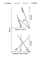
- British Patent No. 1,541,852 describes a piston, driven by a motor which alters the pressure in the piston according to the power supplied to motor.
- This system is designed to deliver pressure according to a predetermined pressure-time profile (as in pressure cycled ventilators) or to force a given volume of gas into the patient (as in volume cycled methods).
- a predetermined pressure-time profile as in pressure cycled ventilators
- volume cycled methods as in volume cycled methods.
- neither pressure nor flow and volume is/are predetermined. Rather, the patient determines his own flow pattern and tidal volume through his own effort, while the ventilator delivers pressure in a manner that parallels the patient's ongoing effort (which is obviously not predetermined).
- Stawitcke (U.S. Pat. No. 4,448,192, U.K. Patent No. 2,121,292) describes a system with motor driven pistons and extremely complex controls, the intent of which are to reduce conflict between patient and ventilator.
- a control system continuously computes an ideal pressure-volume trajectory designed to cause the ventilator to deliver gas in the amount (tidal volume) and flow rate specified by the physician while allowing for different degrees of patient effort. Although this system permits the patient to over-ride physician-specified delivery pattern within an inhalation or over a brief period, the control system readjusts the terms in the equation, so that physician-determined criteria are ultimately met.
- the principle of control is, therefore, similar to volume-cycled methods, in that an increase in patient effort is met with a decrease in machine assist to return ventilator output to what the physician prescribes.
- the main difference from other volume-cycled methods is in the freedom the patient is accorded to transiently over-ride the prescriptions by the physician.
- This principle of operation is diametrically opposite to that executed by the method of the present invention.
- the physician sets targets for volume, flow and timing and the machine alters the various parameters in the control system equation in such a way as to meet physician requirements.
- the proportionalities between pressure, on one hand, and volume and flow on the other hand are the parameters that are predetermined, while the patient is left entirely free to select volume, amount and pattern of flow, and timing of each breath.
- prior art patient ventilation systems provide ventilatory support to a patient in accordance with parameters which are determined mainly by a physician and not by the patient.
- the prior art has required some target flow rate, target pressure, target volume, and/or target frequency or inspiratory or expiratory time. Such requirements give rise to the various problems discussed above.
- the present invention is directed to a quite different approach to ventilatory support from those of the prior art described above.
- the pressure delivered by the ventilator increases in direct proportion to patient effort, and the proportionality applies from breath to breath, as well as continuously throughout each inspiration.
- patient effort is amplified, thereby normalizing the relation between effort and ventilation, while leaving the patient entirely in control of all aspects of his breathing.
- the pressure delivered by the ventilator to the patient reflects the amplitude as well as the time pattern of patient effort (see FIG. 5). There is no target flow rate, no target pressure, no target volume, and no target frequency or inspiratory or expiratory time, as there is in the prior art.
- the ventilation procedure of the present invention may be termed proportional assist ventilation (PAV).
- a novel type of lung ventilator apparatus which delivers PAV with a relatively simple electrically-powered operation.
- the gas pressure at the patient's airway is determined by the action of an electric motor acting on a piston reciprocating in a chamber in relation to any desired command input.
- the electrical motor moves the piston with a force proportional to the magnitude of the power applied to the motor.
- On-going rate of flow (V) and volume of flow (V) of gas moving from chamber to patient are monitored with electronic circuitry that permits the independent adjustment of the gain or amplifications of each of the two signals.
- the electronic circuitry provides electric power to the motor in proportion to the sum of the suitably amplified V and V signals. As is described in more detail below, this procedure causes the device to provide pressure in proporation to patient effort.
- the difference between proportional assist ventilation and other modalities is that the patient has total control over his breathing pattern.
- the apparatus works on the principle of positive feedback, namely the more volume and flow the patient takes, the more pressure the machine provides.
- the adjustable parameter is not a target pressure or a target volume, but a degree of assist (or proportionality) to the patient's breathing pattern.
- the machine may be adjusted to provide a specified amount of pressure/unit of inhaled air.
- the proportionality is set to 20 cmH 2 O/L, the patient has to do half the elastic work and the machine does the other half, and so on. There is no requirement that the patient take in a certain volume or reach a certain pressure. As soon as the patient decreases his own effort, air stops flowing in and the machine stops pumping.
- a method for providing breathing assistance in proportion to patient ongoing inspiratory effort comprises providing a free flow of gas from a gas delivery system to a patient in response to a pressure gradient generated by patient inspiratory effort; determining the rate and volume of flow of the gas to the patient; independently amplifying signals corresponding to the determined rate and volume of flow; and providing a pressure assist to the gas in proportion to the sum of the determined and amplified rate and volume of flow.
- the present invention also provides apparatus for delivering proportional assist ventilation to a patient, comprising means for delivering a free flow of gas to the patient in response to patient inhalatory effort; means operatively connected to the gas delivery means for generating pressure in the free flow of gas in response to an electrical command signal; detection means for detecting the instantaneous volume and rate of gas flow to the patient and for generating a separate electrical signal corresponding in magnitude to each of the detected values; means for selectively applying amplification to each of the electrical signals; and means for generating the electrical command signal to the pressure generating means in proportion to the sum of the amplified electrical signals corresponding in magnitude to the instantaneous rate and volume of flow.
- the first advantage is one of comfort, in that the relation between machine and patient is not only synchronous, but entirely harmonious. There is no fighting between patient and machine, and, in fact, the ventilator becomes an extension of the patient's own muscles. Since with PAV pressure is only delivered if patient effort is present, and the pressure is proportional to patient effort throughout inspiration, the patient must contribute a fraction of the pressure used to expand the patient's chest. The ventilator needs to deliver less pressure for a given tidal volume, as compared with other devices. With other forms of ventilation, patient contribution cannot be relied upon and often patient contribution is antagonistic. The required peak airway pressure is higher with such devices than in the present invention.
- the ventilator is simply an extension of the patient's own muscles and is, hence, subject to all the intrinsic control mechanisms that adjust ventilation to varying needs and protect against various injuries.
- Such control mechanisms can potentially be of considerable benefit.
- the respiratory system is endowed with powerful reflexes to protect the lungs from overdistension. Overdistension would reflexly cause inhibition of inspiratory effort and recruitment of expiratory effort. Since the ventilator ceases its pressure when inspiratory effort is terminated, overdistension would reflexly cause the ventilator to cycle off. The risk of barotrauma is reduced.
- a patient's metabolic needs may vary greatly from time to time as a result of movement, shivering or temperature changes. Normally, the respiratory control changes inspiratory effort so that ventilation matches metabolic demands.
- An essential and distinguishing feature of the procedure of the present invention is that the pressure generated by the ventilator follows the exchange of gas from machine to patient as opposed to leading or causing it, as in conventional devices. Flow and volume must first be altered before the ventilator alters its pressure output.
- the ventilating apparatus of the invention was designed specifically for the purpose of delivering this proportional assist mode, the design principles used to accomplish this end also make it possible to use the machine, with very minor electronic additions, to deliver pressure in proportion to any desired input. This extreme versatility permits adaptations to fit future needs with minimal modification.
- FIG. 1 is a graphical representation of patient effort and respiratory flow and volume
- FIG. 2 is a graphical representative of volume cycled ventilation (VCV) according to one prior art procedure
- FIG. 3 is a graphical representation of pressure support ventilation (PSV), according to another prior art procedure
- FIG. 4 is a graphical representative of airway pressure release ventilation (APRV) according to a further prior art procedure
- FIG. 5 is a graphical representative of proportional assist ventilation (PAV) according to the present invention.
- FIG. 6 is a graphical representative comparing proportional assist ventilation (PAV) in accordance with the present invention with prior art procedures;
- FIG. 7 shows a schematic of a device for providing proportional assist ventilation and a graphical representative of ventilator gain and patient elastance
- FIG. 8 is a schematic representation of a lung ventilator device provided in accordance with one embodiment of the invention.
- FIG. 9 is a schematic representation of the electronic circuitry used with the apparatus of FIG. 8;
- FIG. 10 is a schematic representation of the various command signals for the electronic circuitry of FIG. 9.
- FIG. 11 is a schematic representative of a lung ventilator device for effecting proportional assist ventilation in accordance with another embodiment of the invention.
- Inspiratory effort can be defined as the degree of inspiratory muscle activation (Ei) relative to the maximal possible activation (E max ). Inspiratory activity results in generation of inspiratory pressure (P mus i) according to the relationship:
- f is the function that governs the conversion of activity to pressure. This function is primarily influenced by muscle strength, lung volume (V) and inspiratory flow (V) (see Younes et al, A model for the relation between respiratory neural and mechanical outputs. I.Theory, J.Appl. Physiol 51:963-978, 1981, incorporated herein by reference). Since maximal inspiratory pressure is not affected by volume in the resting tidal volume range and flow at resting levels is associated with very small velocities of muscle shortening relative to the maximal possible velocity (Younes et al, supra), the funcction that governs the relation between effort and P mus is primarily affected by muscle strength under resting levels of ventilation.
- FRC passive Functional Residual Capacity
- V is the volume above ERC
- E rs is the elastance of the respiratory system in the linear range (in cmH 2 O/L)
- V is the flow rate
- R rs is respiratory system (including ventilating apparatus) resistance (in cmH 2 O/L/sec).
- P appl pressure generated by the respiratory muscles
- P vent machine generated pressure
- the latter may take the form of positive pressure at the airway or negative pressure at a body surface (e.g. by tank or cuirass).
- V,V and P vent can be continuously measured and E rs and R rs can be measured or estimated
- P mus can be computed continuously, by any convenient computing device, from the measured values, and the ventilator device made to change pressure in proportion to the instantaneous P mus .
- A is the proportionality between P vent and P mus in cmH 2 O/cmH 2 O.
- K 1 is a gain factor applied to the volume signal (in cmH 2 O/L) and K 2 is a gain factor applied to the flow signal (in cmH 2 O/L/sec).
- equation (3) the use of individually adjustable gain factors for flow and volume permits unequal unloading of the resistive and elastic properties, which may have advantages in particular clinical situations.
- measurement of E rs and R rs are difficult to obtain or are unreliable, but with the use of equation (3), the gain factors for V and V can be separately adjusted to patient comfort, thereby obviating the necessity of having to know E rs and R rs .
- An example of a system which operates in accordance with this principle is shown in FIG. 11 and described below.
- PAV proportional assist ventilation
- a system that operates according to this sequence displays positive feedback.
- such a system is inherently unstable and tends to "run-away", since, as some air leaves the system, it generates pressure which causes more air to leave, causing the system to generate even more pressure, and so on.
- the positive feedback inherent to the ventilator is counteracted by the negative feedback provided by the mechanical properties of the patient, namely elastance and resistance.
- FIG. 7 schematically illustrates how the interaction between a PAV system and a patient tends to eliminate the potential for "run-away” and causes the system to simply amplify the ventilatory consequences of patient effort.
- the upper portion of FIG. 7 illustrates a simple design which satisfies the criteria of a PAV delivery system.
- the patient is attached to a freely-moving piston. Movement of air from the piston to patient is sensed by a flowmeter, resulting in flow and volume signals.
- the latter signals as measurements of the instantaneous rate and instantaneous volume of flow of ga are used to activate a motor which applies force to the back of the piston in proportion to the flow and volume signals.
- Separate gain controls determine the proportionalities between flow and volume on the one hand and the force exerted, namely resulting pressure, on the other hand.
- Such gain volumes are analogous to the terms K 1 and K 2 in equation (3).
- This increased volume is sensed and, according to the gain factor; causes P vent to rise an additional one unit, which itself results in the transfer of one more unit of volume, and so on.
- the extent of amplification of the elastic component of P mus is a function of the gain on the ventilator volume signal (K 1 ) relative to the patients own elastance (E rs ). Since the total elastic pressure (V.E rs ) is balanced in part by the elastic component of P mus (P mus (el)) and in part by the elastic assist of the ventilator (V.K 1 ), it follows that: ##EQU1##
- K 1 is 1/2 E rs , as in the example of FIG. 7, then the amplification factor is 2.
- the amplification factor is 4, and so on.
- K 1 equals or exceeds E rs , amplification would be infinite and a run-away situation would result.
- E rs increases progressively as long as volume increases, a run-away situation produced by the gain factor accidentally being higher than E rs near functional residual capacity, would soon be aborted as lung volume increases and E rs increases.
- FIG. 7 is intended as an oversimplification to explain the principles involved in the present invention.
- the resistance is never zero and part of P mus is expended against the resistance elements of the system (patient plus equipment).
- P mus the resistance component of P mus
- the total pressure used to offset the flow-related pressure gradient is given by V. R, where R is the total resistance for airflow from ventilator to chest wall and includes equipment resistance. This pressure is provided in part by the ventilator (V.K 2 ) and in part by the resistance component of P mus (P mus (res)).
- P mus (res) contributes the largest fraction of P mus early in inspiration with this fraction declining to nearly zero by the end of inspiration.
- the correlation between instantaneous flow, and hence P mus (res), and instantaneous effort, i.e. total P mus is quite poor and, in fact, negative later in inspiration.
- An assist related to flow only therefore, would amplify effort early in inspiration, where effort is small, while leaving the muscles essentially unsupported late in inspiration, where effort is greatest.
- FIG. 7 also should not be interpreted as implying that the control should proceed in a sequential manner as illustrated.
- Analog control circuitry can function just as well. In both cases (digital and analog) the command signal to the pressure generator changes only subsequent to, and not in advance of, a change in flow and volume thereby rendering the ventilator subservient to the patient and not the opposite.
- the second embodiment (FIG. 11) is suitable where the relation between power delivered to motor and pressure in the bellows is linear in the range of motion required for ventilation.
- This is achieved by mechanical design that minimizes inertial and resistive losses during movement of piston or bellows and by insuring that the motor operates in a linear range (i.e. fixed relation between power supply and force output) through the entire clinically-useful volume range of piston or bellows.
- the use of such mechanical design obviates the need for using pressure feedback and error signal to control the motor.
- the use of pressure feedback in the PAV modality destabilizes the device (because the desired pressure is not itself a fixed reference or function but is highly labile and influenced by the pressure in the system). Eliminating the pressure feedback from the command signal, therefore, results in a much more stable system. Filtering can be minimal with enhanced responsiveness of the device. The operation of such device then would be essentially errorless.
- a lung ventilating apparatus 10 comprises a plurality of components housed in housing 12.
- the components located in the housing 12 comprise a rolling seal piston head 14 of low inertia and low resistance, a drive motor 16 for the piston 14, an electrical power supply 18 for the unit 10, and air blower 20 and electronic controls 22.
- the piston head 14 is mounted for reciprocal movement in the housing 12 to provide a chamber 24 of variable volume depending on the position of the piston head 14.
- the cross-sectional area of the piston head 14 as well as the maximum distance of reciprocation determine the range of ventilation for which the unit 10 may be used.
- the piston head 14 should move with little inertia and frictional resistance, so that the initial movement of the piston follows free flow of gas to the patient upon initial patient inhalation effort.
- a light plastic material may be employed as the material of construction, or, as illustrated, an aluminum sheel 26 with a foamed polymer reinforcement, such as, Styrofoam. Frictional resistance to piston movement may be decreased by using high quality bearings and low resistance seals, such as a rolling seal 28 between the piston head 14 and the interior chamber wall 30.
- the chamber 24 is provided with an inlet/outlet opening 32 which is arranged to be joined by a flexible air pipe 34 to the airway of a patient.
- a one-way valve 36 communicates with the pipe 34, to allow ambient gas, usually air, to enter the piston chamber 24 through the inlet/outlet opening 32 during the exhalatory phase of the respiratory cycle, as described in more detail below.
- the chamber 24 is illustrated as possessing an additional gas inlet 38 controlled by a solenoid valve 40 to permit the optional introduction of selected gas mixtures, if desired, to the chamber 24.
- the solenoid valve 40 is opened during expiration as the piston head 14 reciprocates to its baseline position.
- the oxygen content of the inspired gas may be enriched by admitting a continous flow of oxygen into the chamber 24 through an optional gas inlet 42.
- the piston head 14 is mounted on a piston rod 44 for reciprocation of the piston head 14 for the purpose of alternatively decreasing and increasing the volume of the cylinder 24.
- the piston rod 46 is mounted in sliding relation to a suitable bearing 45.
- a position sensing device 46 in the form of a potentiometer, is mounted on the piston rod 44 to provide an electrical signal corresponding to the position of the piston head 14.
- a pressure transducer 48 is operatively connected to the piston chamber 24 to determine the pressure in the chamber 24 which, in turn, determines the force output required by motor 16, as explained in more detail below.
- the piston chamber 24 also is connected to a three-way solenoid valve 50.
- the solenoid valve 50 is connected via tube 51 to an expiratory valve 52 connected by flexible tubing 54 to the patient airway.
- the solenoid valve 50 connects the chamber 24 to the expiratory valve 52, shutting it off.
- the solenoid valve 50 connects the expiratory valve 52 to a variable pressure in order to set the level of positive end-expiratory pressure (PEEP).
- PEEP positive end-expiratory pressure
- the variable pressure is produced by controlling the resistance of a needle valve 55 mounted into the pipe 56 connecting the solenoid valve 50 to the blower 20.
- the motor 16 is of the type which possesses a moving part, such as a shaft or coil, to exert a force in a forward (positive) or backward (negative) direction in proportion to the power applied to the motor 16.
- the maximum force requirement of the motor is determined by the area (A) of the piston head and the maximum pressure range (Pmax) for which the unit 10 is built.
- the equation to calculate the required force is: ##EQU2## Hence, for example, for a piston of area 200 cm 2 and maximum pressure range 50 cm H 2 O, the motor 16 should be able to generate up to 10 kg of force.
- a velocity transducer 57 (FIG. 9) is mounted to the core of the motor 16 to generate a signal 58 proportional to the rate of motion of the piston head 14. This signal is used for a variety of purposes, as described below with respect to FIG. 9.
- the motor 16 is powered by a power line 60 from the electronic module 22 (see also FIG. 9).
- the electronic module 22 functions to provide the electrical signal drive input 60 to the motor 16 to cause the motor 16 to generate a drive force to the piston 14 of a pattern and magnitude that reproduces, as closely as possible, the desired pattern and magnitude of pressure to be delivered to the patient from the chamber 24. It is preferred to employ a fast-responding motor, so that a change in drive input results in an almost instantaneous change in drive force, thereby permitting almost unlimited patterns of pressure applications in response to patient inspiratory effort.
- a large variety of electronic components may be used in the electronic circuitry in conjunction with the pressure generating device (i.e. the combination of motor 16, piston head 14 and power supply 18) to produce a corresponding variety of pressure patterns, as described further below.
- the pressure generating device i.e. the combination of motor 16, piston head 14 and power supply 18
- the motor 16 responds to the instantaneous difference, after suitable amplification, between a desired output, being the command signal, and the actual output.
- a desired output is inputted by line 70 to a summing amplifier 72 to which also is fed a feedback signal (corresponding to the actual state of affairs) by line 74.
- the inspired volume signal is connected to the command signal.
- the pressure in the piston chamber 24, as measured by the pressure transducer 48, is used as feedback. If the measured pressure in the chamber 24 is different from the one desired as determined by the summing amplifier 72, then an error signal is generated in line 76.
- the error signal after suitable amplification by amplifiers 78, 80, then controls the output of a power amplifier 82 which provides the control signal in line 60 to the motor 16.
- the ventilator unit 10 can deliver pressure from the piston chamber 24 in proportion to inspired volume (as just described) or inspired flow rate (with the flow rate used as the command signal).
- the ventilator unit delivers pressure from the piston in response to a combination of the instantaneous inspired volume and inspired flow rate, and in accordance with the desired proportional assist.
- This basis design also can be used to implement other methods of assist as per prior art methods. For example, if a sine wave or a ramp voltage is used as the command signal, the ventilator unit produces pressure in the corresponding manner. As a result of this versatility, it is possible to employ the unit 10 as a high frequency ventilator alone or in combination with volume and flow assist.
- the unit If inspired volume is used as a feedback, the unit also delivers pressure in a pattern which causes inspired volume to follow the pattern of the command signal, thereby functioning as a volume ventilator.
- the summing amplifier 72 also receives feedback from the velocity transducer 57 by line 58. This additional feedback tends to prevent rapid changes in pressure which otherwise may trigger oscillations, as previously discussed with reference to equation (2).
- the output of the velocity transducer 57 reflects the motion of the piston as air moves into the subject as well as motion related to compression or decompression of gas in the system.
- the former component is a relatively slow event whereas the latter component incorporates high frequency components, which are desirable as feedback to prevent oscillations.
- the signal in line 58 is passed through a high pass filter 84.
- the filter output in line 106 is used as a velocity feedback in three arms.
- One arm of the net velocity signal in line 106 is passed through a bidirectional peak clipping circuit 108, which clips the signal above and below an adjustable level.
- the signal so produced in line 110 is amplified and passed to the summing amplifier 72.
- a second arm of the net velocity signal in line 106 is passed through a window clipping circuit 112, which passes only that part of the signal above or below an adjustable level and is designed to abort massive oscillations in the event of failure of other feedback.
- the level above or below which net velocity signal is passed is adjusted to be above the signal level associated with response to the control signal.
- the third arm, in line 114, containing the entire net velocity signal, is passed through an adjustable attenuator with the resulting signal passing by line 118 to the summing amplifier 72. With the two clipping circuits 108 and 112 in place, the gain on the main velocity signal in line 114 need only be small.
- switches permit the operator to select the function or combination of functions to be channeled to the summing amplifier 72 and variable gain controls permit selection of the magnitude of the assist.
- the various functions available for the illustrated embodiment are shown schematically in FIG. 10 and will now be described:
- (b) inspired volume The signal related to inspired flow (line 89) may be integrated in integrator 92 to provide a signal corresponding to inspired volume and hence represents, at any given time, the instantaneous gas flow volume.
- the ventilator unit 10 develops pressure in proportion to inspired volume.
- the magnitude of the assist obtained again may be controlled by a gain device 96 by suitable amplification of the electrical signal corresponding in magnitude to the detected instantaneous inspired flow volume.
- Ramp generator This mode of operation permits the ventilator unit 10 to function independent of patient effort and provides a controlled ventilation. This function can be activated by the operator by throwing switch 98 to bring the function generator 100 into the circuit. Alternatively, provision may be made for the ramp generator to be routed automatically to the summing amplifier 72 in the event of the failure of the patient to breathe spontaneously for a specified period of time (not shown).
- D.C. output An adjustable DC output provided by an offset amplifier 101 also is routed to the summing amplifier 72, to result in the generation of continuous pressure.
- the electronic circuitry 22 also includes cycling controls (not shown) to take into account that air is exchanged between patient and ventilator unit 10 only during the inspiration phase of the respiratory cycle and it is necessary to reset various controls in the "off" phase in preparation for the next cycle. These controls also effect closure of the expiratory valve 52 during the pumping phase.
- the piston head 14 begins to move forward in the chamber 24, either as a result of the patient pulling in (assist mode) or as a result of the piston pushing (in response to a ramp command in the controlled mode).
- This forward motion then generates a flow signal which, when it exceeds a predetermined level, causes the expiratory valve 52 to close to ensure that pressure is conveyed to the patient.
- This result is achieved by summing the flow signal in line 89 with a DC offset voltage in line 102 from offset amplifier 103 and passing the summed signal in line 104 through a zero crossing detection circuit.
- the level of the offset voltage 102 may be varied and usually is kept slightly above zero. Once the flow exceeds this minimal level, a square voltage output is generated which activates valve 50, thereby connecting the chamber 24 to the valve 52 and closing the latter. Flow then continues into the patient as long as patient effort plus pressure output by the ventilator unit 10 exceed the elastic recoil of the respiratory system. When patient effort declines at the end of the patient's spontaneous inspiration, inspiratory flow ceases.
- valve 50 As the flow signal crosses the offset level on its return to zero at the end of the inspiratory cycle, the valve 50 is inactivated, so releasing the pressure in the expiratory valve 52 and allowing the patient to exhale.
- a negative voltage is gated to the summing amplifier 72, which causes the piston head 14 to pull back allowing air to enter the chamber 24 through the one-way valve 36, if air is the desired gas.
- the solenoid valve 40 may be opened at the same time to permit pressurized gas of a specific composition to be admitted.
- the piston head 14 retracts until the piston position, as indicated by the output of the potentiometer 46, reaches a preset level.
- the negative voltage to the summing amplifier 72 is interrupted and the solenoid valve 40 is closed.
- the active command signal is the output of the offset amplifier.
- the pressure in the piston chamber 24 remains at this level throughout the remainder of the expiratory phase and until the beginning of the next inspiratory phase.
- the output of the offset amplifier is normally set just below its PEEP level, so that the patient need only exert minimal effort to get the piston head 14 moving at the beginning of inspiration.
- the electronic circuitry 22 may include safety features powered by battery in the event of power failure. For example, an alarm may be made to sound in the event that there is a power failure, a failure of pressure to cycle for a preset period, an excess pressure or a large inspired volume.
- gauges, read-outs and recorders may be provided to display, store or compilate a variety of parameters, including breath by breath or moving averages, of tidal volume, ventilation frequency, inspiratory duration, duty cycle (inspiratory duration/cycle duration) and respiratory system compliance.
- FIG. 11 there is illustrated therein another preferred embodiment of the invention, which is a much simplified version of the embodiment of FIG. 8, and currently is the best mode known to the applicant for carrying the invention (PAV) into effect.
- a low inertia, low resistance rolling seal piston 201 freely moves within a chamber 202.
- the chamber 202 receives gas through a one-way valve with an appropriate opening pressure level 203 during the exhalation phase while, during the inhalation phase, gas moves from the chamber 202 to patient 208 through another one-way valve 204.
- the piston 201 is coupled to the coil of a linear drive motor 205, which itself moves freely within a fixed magnet 206.
- the coil 205 pushes or pulls on the piston 201 in proportion to the magnitude of the drive potential supplied to the coil 205 via a cable 207.
- any other type of bellows-motor combination would be suitable, provided that the requirement is satisfied that there is permitted a free flow of gas to the patient under a gradient generated by the patient. This requirement can be met either through the inherent mechanical properties (i.e. low inertia, low resistance) of the bellow-motor combinations or through appropriate servo-control of bellows position, as in prior art.
- the rate of flow of gas from the chamber 202 to the patient 208 is measured by a flow meter 209 mounted on the inhalation conduit 210 which generates an instantaneous flow signal.
- the rate of gas flow can be measured using a velocity transducer that monitors the rate of piston movement (not shown).
- the position of the piston 201 is also monitored using a potentiometer 211 or other appropriate device, as described above with respect to FIGS. 8 to 10.
- the instantaneous flow signal (i.e., an electrical signal indicative of the instantaneous rate of flow of gas through the inhalation conduit 210) is conditioned through an externally adjustable gain control 212.
- This is the equivalent of K 2 in equation 3 above.
- the amplification may be constant or variable to allow for non-linear behaviour of the pressure-flow relation of patient and/or external tubing.
- the instantaneous flow signal is also integrated using an integrator 213 to provide a signal corresponding to instantaneous inhaled volume 214 (i.e., an electrical signal indicative of the instantaneous volume of flow of gas through the inhalation conduit 210).
- the latter is also conditioned through an externally adjustable gain control 215.
- the amplified flow and volume signals 216, 217 are summed using a summing amplifier 218, to generate a composite output signal.
- the summing amplifier may also receive other inputs 219 to permit the unit to be operated in a non-proportonal assist mode. These additional inputs are described below.
- a switch mechanism 220 channels the output of the summing amplifier 218 to the motor 205 during the inhalation phase and the later part of the exhalation phase. During the early part of the exhalation, the switch 220 channels instead a constant negative voltage 221 to return the piston 201 to a preset location, as judged by the potentiometer signal 211. In either case, the command signal 222 is first suitably amplified using a power amplifier 223 and power supply 224.
- exhalation tube 225 and exhalation valve 226 insure gas flow from patient to the ambient atmosphere during the exhalation phase. Any of a variety of commercially available exhalation valves can be used.
- the exhalation valve 226 is opened or closed according to its valve control mechanism 228.
- a differential pressure transducer 227 measures the pressure gradient between a point upstream and a point downstream from the one-way valve 204 that directs flow on the inhalation line 210.
- the downstream point is preferably as close as possible to the patient to enhance the sensitivity of the transducer 227 to flow, while the upstream point may be conveniently located at the chamber 202.
- the inhalation phase is defined as any time during which the pressure upstream is higher than the pressure at the point nearer the patient.
- the exhalation phase is when pressure on the patient side of the valve 204 is higher than in the chamber 202.
- the output of the differential transducer 227 is channeled to the exhalation valve control mechanism 228 and to the switching mechanism 220 for the motor drive 205.
- the integrator 213 At transition from inhalation to exhalation, as defined by transducer 227 output, the integrator 213 is reset to return the volume signal 214 to zero, in preparation for the next cycle.
- Other inputs 219 to the summing amplifier 218 may include any of a variety of functions. Two preferred functions are a constant voltage, to provide continuous positive airway pressure (CPAP) if desired, and an input designed to cancel out the effect of inhalation tube resistance. In the latter case, the output of the differential transducer 227 is channeled to the summing amplifier 218 after suitable amplification and rectification (positive gradients from chamber to patient only). In this fashion, the piston generates a positive pressure component that equals the pressure gradient between chamber and patient, thereby essentially eliminating the resistive effect of the tubing at all flow rates.
- CPAP continuous positive airway pressure
- Other inputs 219 may also include back-up functions, for example repetitive ramp or square wave voltage vs time functions to insure ventilation in the event of apnea.
- back-up functions for example repetitive ramp or square wave voltage vs time functions to insure ventilation in the event of apnea.
- manufacturers may wish to add other types of conventional ventilation methods in machines that deliver PAV, so that these additional methods, for example, airway pressure release ventilation (APRV) or synchronized intermittent mandatory ventilation (SIMV) or pressure support (PS), may be used jointly or alternately with PAV.
- APRV airway pressure release ventilation
- SIMV synchronized intermittent mandatory ventilation
- PS pressure support
- the piston 201 retracts under the influence of the negative voltage 221, acquiring fresh gas of a desired composition through the one-way valve 203 until it reaches a preset level.
- the switching mechanism 220 then disconnects the negative voltage and channels the output of the summing amplifier 218 to the motor 205.
- the conditioned flow signal 216 is zero and the conditioned volume signal 217 is also zero as a result of integrator 213 resetting.
- the only drive is from other inputs 219. In the event a constant voltage is applied via other inputs 219, the motor 205 will pressurize the piston 201 to a constant level in preparation for the next inhalation.
- the level of constant pressure is typically set to be just below the level of desired positive end expiratory pressure (PEEP), as determined by the exhalation valve control or other suitable PEEP device.
- PEEP positive end expiratory pressure
- the output of the summing amplifier changes according to the sum of the conditioned flow 216 and volume 217 signals and the constant voltage, if any, via other inputs 219. This causes the pressure in the chamber 202 to rise.
- the chamber pressure is not adequate by itself to entirely support the elastic recoil and resistive pressure losses and the patient is, therefore, contributing to the total pressure, and flow and volume remain responsive to patient effort.
- the patient terminates his own respiratory effort, there is accordingly not enough pressure to sustain the elastic recoil of the respiratory system.
- Pressure in the airway rises above chamber pressure and this, via the differential pressure transducer 227, causes the opening of the exhalation valve 226, resetting of the integrator 223 and hence loss of chamber pressure and the cycle is repeated.
- this design has the distinct advantage of making it unnecessary to utilize servo-feedback of pressure output, as is necessary in the embodiment of FIGS. 8 to 10.
- the present invention provides a novel ventilation unit and ventilating procedure which are able to deliver air to a patient in proportion to patient ongoing inspiratory effort (Proportinoal Assist Ventilation, PAV). Modifications are possible within the scope of this invention.
Abstract
Description
[i.e. E.sub.max ]P.sub.mus i=fEi/E.sub.max
P.sub.appl =P.sub.el +P.sub.res
P.sub.appl =V·E.sub.rs +V·R.sub.rs
P.sub.mus +P.sub.vent =V·E.sub.rs +V·R.sub.rs(1)
P.sub.mus =V·E.sub.rs +V·R.sub.rs -P.sub.vent(2)
P.sub.vent =A·P.sub.mus
P.sub.vent =K.sub.1 V+K.sub.2 V (3)
P.sub.vent =A·V·E.sub.rs +A·V·R.sub.rs -A·P.sub.vent
P.sub.vent (1+A)=A·E.sub.rs ·V+A·R.sub.rs ·V
P.sub.vent =[A/(1+A)]E.sub.rs ·V+[A/(1+A)]R.sub.rs ·V
F(el)-V·E.sub.rs /V[E.sub.rs -K.sub.1 ]=E.sub.rs /[E.sub.rs -K.sub.1 ]
F(res)=R/[R-K2]
Claims (16)
P.sub.vent =K.sub.1 V+K.sub.2 V
P.sub.vent =A·P.sub.mus
P.sub.mus =V·E.sub.rs +V·R.sub.rs -P.sub.vent
Priority Applications (3)
| Application Number | Priority Date | Filing Date | Title |
|---|---|---|---|
| CA002038971A CA2038971C (en) | 1990-03-30 | 1991-03-25 | Lung ventilator device |
| EP01104067A EP1103279A3 (en) | 1990-03-30 | 1991-03-28 | Lung ventilator device |
| EP19910302754 EP0452001A3 (en) | 1990-03-30 | 1991-03-28 | Lung ventilator device |
Applications Claiming Priority (2)
| Application Number | Priority Date | Filing Date | Title |
|---|---|---|---|
| GB8704104 | 1987-02-21 | ||
| GB878704104A GB8704104D0 (en) | 1987-02-21 | 1987-02-21 | Respiratory system load apparatus |
Related Parent Applications (1)
| Application Number | Title | Priority Date | Filing Date |
|---|---|---|---|
| US07/496,172 Continuation-In-Part US5044362A (en) | 1987-02-21 | 1990-03-20 | Lung ventilator device |
Publications (1)
| Publication Number | Publication Date |
|---|---|
| US5107830A true US5107830A (en) | 1992-04-28 |
Family
ID=10612718
Family Applications (2)
| Application Number | Title | Priority Date | Filing Date |
|---|---|---|---|
| US07/496,172 Expired - Lifetime US5044362A (en) | 1987-02-21 | 1990-03-20 | Lung ventilator device |
| US07/501,757 Expired - Lifetime US5107830A (en) | 1987-02-21 | 1990-03-30 | Lung ventilator device |
Family Applications Before (1)
| Application Number | Title | Priority Date | Filing Date |
|---|---|---|---|
| US07/496,172 Expired - Lifetime US5044362A (en) | 1987-02-21 | 1990-03-20 | Lung ventilator device |
Country Status (8)
| Country | Link |
|---|---|
| US (2) | US5044362A (en) |
| EP (1) | EP0283141B1 (en) |
| AT (1) | ATE128036T1 (en) |
| CA (1) | CA1319175C (en) |
| DE (1) | DE3854482T2 (en) |
| ES (1) | ES2076158T3 (en) |
| GB (1) | GB8704104D0 (en) |
| GR (1) | GR3017454T3 (en) |
Cited By (188)
| Publication number | Priority date | Publication date | Assignee | Title |
|---|---|---|---|---|
| US5271388A (en) * | 1989-06-07 | 1993-12-21 | Caduceus Limited | Medical ventilator |
| US5303698A (en) * | 1991-08-27 | 1994-04-19 | The Boc Group, Inc. | Medical ventilator |
| US5307795A (en) * | 1989-06-07 | 1994-05-03 | Caduceus Limited | Medical ventilators |
| US5313937A (en) * | 1989-09-22 | 1994-05-24 | Respironics Inc. | Leak compensation method and apparatus for a breathing system |
| US5385142A (en) * | 1992-04-17 | 1995-01-31 | Infrasonics, Inc. | Apnea-responsive ventilator system and method |
| US5400777A (en) * | 1990-10-31 | 1995-03-28 | Siemens Aktiengesellschaft | Ventilator |
| US5438980A (en) * | 1993-01-12 | 1995-08-08 | Puritan-Bennett Corporation | Inhalation/exhalation respiratory phase detection circuit |
| US5492113A (en) * | 1991-11-01 | 1996-02-20 | Respironics, Inc | Sleep apnea treatment apparatus having multiple ramp cycles |
| US5531221A (en) * | 1994-09-12 | 1996-07-02 | Puritan Bennett Corporation | Double and single acting piston ventilators |
| US5535738A (en) * | 1994-06-03 | 1996-07-16 | Respironics, Inc. | Method and apparatus for providing proportional positive airway pressure to treat sleep disordered breathing |
| US5540222A (en) * | 1991-02-19 | 1996-07-30 | University Of Manitoba | Piston-based ventilator design and operation |
| US5596984A (en) * | 1994-09-12 | 1997-01-28 | Puritan-Bennett Corporation | Lung ventilator safety circuit |
| WO1997022377A1 (en) * | 1995-12-20 | 1997-06-26 | University Of Manitoba | Device for the determination of at least two parameters of a patient's respiratory system and method therefor |
| US5645053A (en) * | 1991-11-14 | 1997-07-08 | University Technologies International, Inc. | Auto CPAP system and method for preventing patient disturbance using airflow profile information |
| US5660171A (en) * | 1990-05-11 | 1997-08-26 | Puritan-Bennett Corporation | System and method for flow triggering of pressure supported ventilation by comparison of inhalation and exhalation flow rates |
| US5664560A (en) * | 1995-02-08 | 1997-09-09 | Puritan-Bennett Corporation | Gas mixing apparatus for a ventilator |
| US5673689A (en) * | 1995-02-09 | 1997-10-07 | Puritan Bennett Corporation | Piston based ventilator |
| US5683232A (en) * | 1994-02-28 | 1997-11-04 | Adahan; Carmeli | Pump particularly useful in respirator apparatus and exhalation valve assembly thereof |
| US5694926A (en) | 1994-10-14 | 1997-12-09 | Bird Products Corporation | Portable drag compressor powered mechanical ventilator |
| US5694924A (en) * | 1995-10-19 | 1997-12-09 | Siemens-Elema Ab | Anesthetic administration system with active regulation of the volume of the gas reservoir during a breathing cycle |
| US5720278A (en) * | 1995-12-01 | 1998-02-24 | Siemens Elema Ab | Inverse proportional assist ventilation apparatus |
| US5794615A (en) * | 1994-06-03 | 1998-08-18 | Respironics, Inc. | Method and apparatus for providing proportional positive airway pressure to treat congestive heart failure |
| US5803065A (en) * | 1989-09-22 | 1998-09-08 | Respironics Inc. | Breathing gas delivery method and apparatus |
| US5813399A (en) * | 1993-03-16 | 1998-09-29 | Puritan Bennett Corporation | System and method for closed loop airway pressure control during the inspiratory cycle of a breath in a patient ventilator using the exhalation valve as a microcomputer-controlled relief valve |
| US5820572A (en) * | 1995-11-21 | 1998-10-13 | The Penn State Research Foundation | Negative pressure chest brace |
| US5865173A (en) * | 1995-11-06 | 1999-02-02 | Sunrise Medical Hhg Inc. | Bilevel CPAP system with waveform control for both IPAP and EPAP |
| US5884622A (en) * | 1996-12-20 | 1999-03-23 | University Of Manitoba | Automatic determination of passive elastic and resistive properties of the respiratory system during assisted mechanical ventilation |
| US5931162A (en) * | 1996-06-03 | 1999-08-03 | Siemens Aktiengesellschaft | Ventilator which allows spontaneous inhalation and expiration within a controlled breathing mode |
| WO2000010634A1 (en) | 1998-08-21 | 2000-03-02 | Respironics, Inc. | Apparatus and method for determining respiratory mechanics of a patient and for controlling a ventilator based thereon |
| US6091973A (en) * | 1995-04-11 | 2000-07-18 | Resmed Limited | Monitoring the occurrence of apneic and hypopneic arousals |
| US6105575A (en) * | 1994-06-03 | 2000-08-22 | Respironics, Inc. | Method and apparatus for providing positive airway pressure to a patient |
| US6119723A (en) | 1997-02-14 | 2000-09-19 | Resmed Limited, | Apparatus for varying the flow area of a conduit |
| US6123082A (en) | 1996-12-18 | 2000-09-26 | Resmed Limited | Device for preventing or reducing the passage of air through the mouth |
| US6135967A (en) | 1999-04-26 | 2000-10-24 | Fiorenza; Anthony Joseph | Respiratory ventilator with automatic flow calibration |
| US6138675A (en) * | 1993-11-05 | 2000-10-31 | Resmed Ltd. | Determination of the occurrence of an apnea |
| US6142150A (en) * | 1998-03-24 | 2000-11-07 | Nellcor Puritan-Bennett | Compliance compensation in volume control ventilator |
| US6155986A (en) * | 1995-06-08 | 2000-12-05 | Resmed Limited | Monitoring of oro-nasal respiration |
| US6182657B1 (en) | 1995-09-18 | 2001-02-06 | Resmed Limited | Pressure control in CPAP treatment or assisted respiration |
| US6213119B1 (en) * | 1995-10-23 | 2001-04-10 | Resmed Limited | Inspiratory duration in CPAP or assisted respiration treatment |
| US6216691B1 (en) | 1997-11-03 | 2001-04-17 | Resmed Limited | Mounting body |
| US6237592B1 (en) | 1995-07-03 | 2001-05-29 | Resmed Limited | Auto-calibration of pressure transducer offset |
| US6240921B1 (en) | 1993-12-01 | 2001-06-05 | Resmed, Ltd. | Automated stop/start control in the administration of CPAP treatment |
| US6240919B1 (en) | 1999-06-07 | 2001-06-05 | Macdonald John J. | Method for providing respiratory airway support pressure |
| US6253764B1 (en) | 1996-05-08 | 2001-07-03 | Resmed, Ltd. | Control of delivery pressure in CPAP treatment or assisted respiration |
| US6279569B1 (en) | 1996-08-14 | 2001-08-28 | Resmed Limited | Determination of leak and respiratory airflow |
| US6321748B1 (en) | 1998-03-10 | 2001-11-27 | Nellcor Puritan Bennett | Closed loop control in a piston ventilator |
| US6332463B1 (en) | 1995-09-15 | 2001-12-25 | Resmed Limited | Flow estimation and compensation of flow-induced pressure swings in CPAP treatment and assisted respiration |
| US6336454B1 (en) | 1997-05-16 | 2002-01-08 | Resmed Limited | Nasal ventilation as a treatment for stroke |
| US6397841B1 (en) | 1997-06-18 | 2002-06-04 | Resmed Limited | Apparatus for supplying breathable gas |
| US6398739B1 (en) | 1987-06-26 | 2002-06-04 | Resmed Limited | Device and method for nonclinical monitoring of breathing during sleep, control of CPAP treatment and preventing apnea |
| US6439229B1 (en) * | 2000-08-08 | 2002-08-27 | Newport Medical Instruments, Inc. | Pressure support ventilation control system and method |
| US6467477B1 (en) | 1999-03-26 | 2002-10-22 | Respironics, Inc. | Breath-based control of a therapeutic treatment |
| WO2003008027A1 (en) * | 2001-07-19 | 2003-01-30 | Resmed Ltd. | Pressure support ventilation of patients |
| JP2003509134A (en) * | 1999-09-15 | 2003-03-11 | レスメッド・リミテッド | Synchronizing patient and ventilator using two phase sensors |
| US6533739B1 (en) | 1995-11-21 | 2003-03-18 | The Penn State Research Foundation | Chest brace and method of using same |
| US6532959B1 (en) | 1998-05-22 | 2003-03-18 | Resmed, Ltd. | Ventilatory assistance for treatment of cardiac failure and cheyne-stokes breathing |
| US6532957B2 (en) | 1996-09-23 | 2003-03-18 | Resmed Limited | Assisted ventilation to match patient respiratory need |
| US6532956B2 (en) | 2000-03-30 | 2003-03-18 | Respironics, Inc. | Parameter variation for proportional assist ventilation or proportional positive airway pressure support devices |
| US6571795B2 (en) | 1992-06-15 | 2003-06-03 | Nellcor Puritan Bennett France Developpement | Breathing aid apparatus in particular for treating sleep apnoea |
| US20030111078A1 (en) * | 2001-06-21 | 2003-06-19 | Habashi Nader Maher | Ventilation method and control of a ventilator based on same |
| US6581596B1 (en) * | 1999-09-24 | 2003-06-24 | Respironics, Inc. | Apparatus and method of providing high frequency variable pressure to a patient |
| US20030121519A1 (en) * | 1994-06-03 | 2003-07-03 | Estes Mark C. | Method and apparatus for providing positive airway pressure to a patient |
| US6588422B1 (en) * | 1999-01-15 | 2003-07-08 | Resmed Ltd. | Method and apparatus to counterbalance intrinsic positive end expiratory pressure |
| US20030145855A1 (en) * | 1999-08-03 | 2003-08-07 | Fuhrman Bradley P. | Device and method of reducing bias flow in oscillatory ventilators |
| US20030159700A1 (en) * | 1997-04-07 | 2003-08-28 | Laufer Michael D. | Method of increasing gas exchange of a lung |
| US6629527B1 (en) | 1991-10-17 | 2003-10-07 | Respironics, Inc. | Sleep apnea treatment apparatus |
| US6629934B2 (en) | 2000-02-02 | 2003-10-07 | Healthetech, Inc. | Indirect calorimeter for medical applications |
| US20030188748A1 (en) * | 1998-06-04 | 2003-10-09 | Christer Sinderby | Automatic adjustment of applied levels of ventilatory support and extrinsic peep by closed-loop control of neuro-ventilatory efficiency |
| US6631716B1 (en) * | 1998-07-17 | 2003-10-14 | The Board Of Trustees Of The Leland Stanford Junior University | Dynamic respiratory control |
| US6634363B1 (en) * | 1997-04-07 | 2003-10-21 | Broncus Technologies, Inc. | Methods of treating lungs having reversible obstructive pulmonary disease |
| US6651657B1 (en) * | 1999-12-18 | 2003-11-25 | DRäGER MEDIZINTECHNIK GMBH | Respirator for different forms of respiration |
| US6672300B1 (en) * | 1999-06-23 | 2004-01-06 | Graham Cameron Grant | Respiration assistor |
| US6679258B1 (en) * | 1998-08-25 | 2004-01-20 | Siemens Elema Ab | Ventilator operable in a compensated volume support mode |
| US20040016433A1 (en) * | 1991-11-01 | 2004-01-29 | Respironics, Inc. | Sleep apnea treatment apparatus |
| US6758216B1 (en) | 1999-09-15 | 2004-07-06 | Resmed Limited | Ventilatory assistance using an external effort sensor |
| US6770037B2 (en) | 1987-06-26 | 2004-08-03 | Resmed Limited | Method and apparatus useful in the diagnosis of obstructive sleep apnea of a patient |
| US20040200472A1 (en) * | 2003-01-09 | 2004-10-14 | Suny Stony Brook/Respironics | Method of treating functional somatic syndromes and diagnosing sleep disorders based on functional somatic syndrome symptoms |
| US6837242B2 (en) | 2000-04-26 | 2005-01-04 | The University Of Manitoba | Method and apparatus for determining respiratory system resistance during assisted ventilation |
| US6866040B1 (en) | 1994-09-12 | 2005-03-15 | Nellcor Puritan Bennett France Developpement | Pressure-controlled breathing aid |
| US20050187579A1 (en) * | 1997-04-07 | 2005-08-25 | Asthmatx, Inc. | Method for treating an asthma attack |
| US20060021620A1 (en) * | 1996-12-12 | 2006-02-02 | Resmed Limited | Method and apparatus for substance delivery in system for supplying breathable gas |
| US20060070624A1 (en) * | 2004-10-01 | 2006-04-06 | Ric Investments, Llc | Method and apparatus for treating cheyne-stokes respiration |
| US7044129B1 (en) | 2003-09-03 | 2006-05-16 | Ric Investments, Llc. | Pressure support system and method |
| US7128069B2 (en) | 2003-06-20 | 2006-10-31 | Resmed Limited | Method and apparatus for improving the comfort of CPAP |
| US20070100390A1 (en) * | 2000-10-17 | 2007-05-03 | Asthmatx, Inc. | Modification of airways by application of energy |
| US20070102011A1 (en) * | 1998-06-10 | 2007-05-10 | Asthmatx, Inc. | Methods of evaluating individuals having reversible obstructive pulmonary disease |
| US20070101999A1 (en) * | 2005-11-08 | 2007-05-10 | Viasys Manufacturing, Inc. | High frequency oscillator ventilator |
| US20070119454A1 (en) * | 1991-12-20 | 2007-05-31 | Resmed Limited | Patient interface assembly for CPAP respiratory apparatus |
| US20070157930A1 (en) * | 2006-01-10 | 2007-07-12 | Viasys Manufacturing, Inc. | System and method for circuit compliance compensated volume assured pressure control in a patient respiratory ventilator |
| US20070209662A1 (en) * | 1999-11-01 | 2007-09-13 | Ric Investments, Llc | Method and apparatus for monitoring and controlling a medical device |
| US20070221221A1 (en) * | 2006-02-23 | 2007-09-27 | Cooke Richard H | Ventilator for Rapid Response to Respiratory Disease Conditions |
| US20070273216A1 (en) * | 2006-05-24 | 2007-11-29 | Farbarik John M | Systems and Methods for Reducing Power Losses in a Medical Device |
| US20070272242A1 (en) * | 2006-04-21 | 2007-11-29 | Sanborn Warren G | Work of breathing display for a ventilation system |
| US20070274693A1 (en) * | 2006-05-24 | 2007-11-29 | Farbarik John M | Systems and Methods for Regulating Power in a Medical Device |
| US7305987B2 (en) * | 2000-03-24 | 2007-12-11 | Gottlieb Weinmann Gerate Fur Medizin Und Arbeitsschutz Gmbh & Co. | Procedure for the control of a respirator device as well as apparatus for monitoring |
| US20080066754A1 (en) * | 2006-09-15 | 2008-03-20 | Faram Joseph D | Continuous high-frequency oscillation breathing treatment apparatus |
| US20080115787A1 (en) * | 2006-06-30 | 2008-05-22 | Aeris Therapeutics | Respiratory assistance apparatus and method |
| WO2008100859A2 (en) | 2007-02-12 | 2008-08-21 | Ric Investments, Llc | Pressure support system and method with automatic comfort feature modification |
| US20080216833A1 (en) * | 2007-03-07 | 2008-09-11 | Pujol J Raymond | Flow Sensing for Gas Delivery to a Patient |
| US20080283051A1 (en) * | 2007-05-18 | 2008-11-20 | Joseph Dee Faram | Lung therapy device |
| US20090007915A1 (en) * | 2006-01-30 | 2009-01-08 | Hamilton Medical Ag | Apparatus for regulating a mechanical ventilation |
| US20090020121A1 (en) * | 2004-01-07 | 2009-01-22 | David John Bassin | Methods for providing expiratory pressure relief in positive airway pressure therapy |
| US20090069797A1 (en) * | 1997-04-07 | 2009-03-12 | Asthmatx, Inc. | Bipolar devices for modification of airways by transfer of energy |
| US20090082831A1 (en) * | 2007-09-21 | 2009-03-26 | Paul Zachary D | Vestibular Stimulation System |
| US20090114222A1 (en) * | 2007-11-02 | 2009-05-07 | Drager Medical Ag & Co. Kg | Process for operating a respirator or anesthesia device in the aprv mode taking into account the impedance and/or the impedance change |
| US20090114224A1 (en) * | 2007-11-07 | 2009-05-07 | Drager Medical Ag & Co. Kg | Method for automatically controlling a ventilation or breathing system as well as a corresponding ventilation or breathing system |
| US20090156953A1 (en) * | 2007-05-18 | 2009-06-18 | Breathe Technologies, Inc. | Methods and devices for sensing respiration and providing ventilation therapy |
| US20090159082A1 (en) * | 2007-12-21 | 2009-06-25 | Drager Medical Ag & Co. Kg | Method of automatically controlling a respiration system and a corresponding respirator |
| US20090165795A1 (en) * | 2007-12-31 | 2009-07-02 | Nellcor Puritan Bennett Llc | Method and apparatus for respiratory therapy |
| US20090301488A1 (en) * | 2005-11-23 | 2009-12-10 | Jianguo Sun | Method And Apparatus For Providing Positive Airway Pressure To A Patient |
| US20100186744A1 (en) * | 2003-07-29 | 2010-07-29 | Claude Andrieux | System and process for supplying respiratory gas under pressure or volumetrically |
| US7837679B2 (en) | 2000-10-17 | 2010-11-23 | Asthmatx, Inc. | Control system and process for application of energy to airway walls and other mediums |
| US20100306992A1 (en) * | 2006-02-23 | 2010-12-09 | Richard Henry Cooke | Ventilator for Rapid Response to Respiratory Disease Conditions |
| US20100312575A1 (en) * | 2007-12-04 | 2010-12-09 | Koninklijke Philips Electronics N.V. | Method of operating a medical device |
| EP2263635A1 (en) | 2001-05-25 | 2010-12-22 | Respironics, Inc. | Exhaust port assembly for a pressure support system |
| GB2472116A (en) * | 2009-07-25 | 2011-01-26 | Fleur T Tehrani | A method and an apparatus for controlling a ventilator to automatically adjust ventilation assistance to an active or passive subject |
| US7909033B2 (en) | 2006-05-03 | 2011-03-22 | Comedica Incorporated | Breathing treatment apparatus |
| US7921855B2 (en) | 1998-01-07 | 2011-04-12 | Asthmatx, Inc. | Method for treating an asthma attack |
| US20110088697A1 (en) * | 2003-08-04 | 2011-04-21 | Devries Douglas F | Mechanical ventilation system utilizing bias valve |
| US20110100364A1 (en) * | 2009-11-02 | 2011-05-05 | Joseph Dee Faram | Multiple conduit connector apparatus and method |
| US20110100360A1 (en) * | 2009-11-02 | 2011-05-05 | Joseph Dee Faram | Composite lung therapy device and method |
| WO2011080604A1 (en) | 2009-12-28 | 2011-07-07 | Koninklijke Philips Electronics N.V. | Exhaust port assembly that minimizes noise |
| WO2011086434A1 (en) | 2010-01-14 | 2011-07-21 | Koninklijke Philips Electronics N.V. | Servo ventilation using pressure drop from baseline |
| WO2011086435A2 (en) | 2010-01-14 | 2011-07-21 | Koninklijke Philips Electronics N.V. | Servo ventilation using negative pressure support |
| US20110209705A1 (en) * | 2003-08-11 | 2011-09-01 | Breathe Technologies, Inc. | Tracheal catheter and prosthesis and method of respiratory support of a patient |
| US20120000466A1 (en) * | 2003-06-18 | 2012-01-05 | New York University | System and Method for Improved Treatment of Sleeping Disorders using Therapeutic Positive Airway Pressure |
| US8136527B2 (en) | 2003-08-18 | 2012-03-20 | Breathe Technologies, Inc. | Method and device for non-invasive ventilation with nasal interface |
| US8181656B2 (en) | 1998-06-10 | 2012-05-22 | Asthmatx, Inc. | Methods for treating airways |
| US20120167885A1 (en) * | 2010-12-29 | 2012-07-05 | Nellcor Puritan Bennett Llc | Systems And Methods For Ventilation To Obtain A Predetermined Patient Effort |
| US8251070B2 (en) | 2000-03-27 | 2012-08-28 | Asthmatx, Inc. | Methods for treating airways |
| US8251876B2 (en) | 2008-04-22 | 2012-08-28 | Hill-Rom Services, Inc. | Breathing exercise apparatus |
| US8302602B2 (en) | 2008-09-30 | 2012-11-06 | Nellcor Puritan Bennett Llc | Breathing assistance system with multiple pressure sensors |
| US8360060B2 (en) | 1993-11-05 | 2013-01-29 | Resmed Limited | Distinguishing between closed and open airway apneas and treating patients accordingly |
| US8381729B2 (en) | 2003-06-18 | 2013-02-26 | Breathe Technologies, Inc. | Methods and devices for minimally invasive respiratory support |
| US20130056006A1 (en) * | 2010-05-11 | 2013-03-07 | Koninklijke Philips Electronics N.V. | Inductance compensation in a pressure support system |
| US8418694B2 (en) | 2003-08-11 | 2013-04-16 | Breathe Technologies, Inc. | Systems, methods and apparatus for respiratory support of a patient |
| US8434482B2 (en) | 2006-03-15 | 2013-05-07 | Carefusion 207, Inc. | Closed loop control system for a high frequency oscillation ventilator |
| US20130133655A1 (en) * | 2009-12-15 | 2013-05-30 | Koninklijke Philips Electronics N.V. | System and method for supporting sub-physiologic and physiologic tidal volumes in spontaneous or non-spontaneous breathing during high frequency ventilation |
| US8483831B1 (en) | 2008-02-15 | 2013-07-09 | Holaira, Inc. | System and method for bronchial dilation |
| US8567399B2 (en) | 2007-09-26 | 2013-10-29 | Breathe Technologies, Inc. | Methods and devices for providing inspiratory and expiratory flow relief during ventilation therapy |
| US8677999B2 (en) | 2008-08-22 | 2014-03-25 | Breathe Technologies, Inc. | Methods and devices for providing mechanical ventilation with an open airway interface |
| US8720441B2 (en) | 2008-08-28 | 2014-05-13 | St. Michael's Hospital | Determining patient-ventilator breath contribution index in spontaneously breathing, mechanically ventilated patients |
| US8740895B2 (en) | 2009-10-27 | 2014-06-03 | Holaira, Inc. | Delivery devices with coolable energy emitting assemblies |
| US8770193B2 (en) | 2008-04-18 | 2014-07-08 | Breathe Technologies, Inc. | Methods and devices for sensing respiration and controlling ventilator functions |
| US8776792B2 (en) | 2011-04-29 | 2014-07-15 | Covidien Lp | Methods and systems for volume-targeted minimum pressure-control ventilation |
| US8776793B2 (en) | 2008-04-18 | 2014-07-15 | Breathe Technologies, Inc. | Methods and devices for sensing respiration and controlling ventilator functions |
| US8783250B2 (en) | 2011-02-27 | 2014-07-22 | Covidien Lp | Methods and systems for transitory ventilation support |
| US8808280B2 (en) | 2008-05-09 | 2014-08-19 | Holaira, Inc. | Systems, assemblies, and methods for treating a bronchial tree |
| US8826907B2 (en) | 2008-06-06 | 2014-09-09 | Covidien Lp | Systems and methods for determining patient effort and/or respiratory parameters in a ventilation system |
| US8844537B1 (en) | 2010-10-13 | 2014-09-30 | Michael T. Abramson | System and method for alleviating sleep apnea |
| US8911439B2 (en) | 2009-11-11 | 2014-12-16 | Holaira, Inc. | Non-invasive and minimally invasive denervation methods and systems for performing the same |
| US8925545B2 (en) | 2004-02-04 | 2015-01-06 | Breathe Technologies, Inc. | Methods and devices for treating sleep apnea |
| US8939152B2 (en) | 2010-09-30 | 2015-01-27 | Breathe Technologies, Inc. | Methods, systems and devices for humidifying a respiratory tract |
| US8955518B2 (en) | 2003-06-18 | 2015-02-17 | Breathe Technologies, Inc. | Methods, systems and devices for improving ventilation in a lung area |
| US8985099B2 (en) | 2006-05-18 | 2015-03-24 | Breathe Technologies, Inc. | Tracheostoma spacer, tracheotomy method, and device for inserting a tracheostoma spacer |
| WO2015082666A1 (en) * | 2013-12-06 | 2015-06-11 | Institut National De La Sante Et De La Recherche Medicale (Inserm) | Breathing simulator, system and method for calibrating a gas flowmeter with such a breathing simulator |
| US9132250B2 (en) | 2009-09-03 | 2015-09-15 | Breathe Technologies, Inc. | Methods, systems and devices for non-invasive ventilation including a non-sealing ventilation interface with an entrainment port and/or pressure feature |
| US9149328B2 (en) | 2009-11-11 | 2015-10-06 | Holaira, Inc. | Systems, apparatuses, and methods for treating tissue and controlling stenosis |
| US20150290407A1 (en) * | 2014-04-11 | 2015-10-15 | Carefusion 2200, Inc. | Lung ventilation apparatus |
| US9179861B2 (en) | 2009-01-16 | 2015-11-10 | St. Michael's Hospital | Method for measuring changes in inspiratory load |
| US9180270B2 (en) | 2009-04-02 | 2015-11-10 | Breathe Technologies, Inc. | Methods, systems and devices for non-invasive open ventilation with gas delivery nozzles within an outer tube |
| US9180271B2 (en) | 2012-03-05 | 2015-11-10 | Hill-Rom Services Pte. Ltd. | Respiratory therapy device having standard and oscillatory PEP with nebulizer |
| US9272132B2 (en) | 2012-11-02 | 2016-03-01 | Boston Scientific Scimed, Inc. | Medical device for treating airways and related methods of use |
| US9283374B2 (en) | 2012-11-05 | 2016-03-15 | Boston Scientific Scimed, Inc. | Devices and methods for delivering energy to body lumens |
| US9339618B2 (en) | 2003-05-13 | 2016-05-17 | Holaira, Inc. | Method and apparatus for controlling narrowing of at least one airway |
| US9358355B2 (en) | 2013-03-11 | 2016-06-07 | Covidien Lp | Methods and systems for managing a patient move |
| US9375542B2 (en) | 2012-11-08 | 2016-06-28 | Covidien Lp | Systems and methods for monitoring, managing, and/or preventing fatigue during ventilation |
| US9398933B2 (en) | 2012-12-27 | 2016-07-26 | Holaira, Inc. | Methods for improving drug efficacy including a combination of drug administration and nerve modulation |
| US9592086B2 (en) | 2012-07-24 | 2017-03-14 | Boston Scientific Scimed, Inc. | Electrodes for tissue treatment |
| US9713690B2 (en) | 2007-08-17 | 2017-07-25 | Resmed Limited | Methods and apparatus for pressure therapy in the treatment of sleep disordered breathing |
| US9770293B2 (en) | 2012-06-04 | 2017-09-26 | Boston Scientific Scimed, Inc. | Systems and methods for treating tissue of a passageway within a body |
| US9795752B2 (en) | 2012-12-03 | 2017-10-24 | Mhs Care-Innovation, Llc | Combination respiratory therapy device, system, and method |
| US9839760B2 (en) | 2014-04-11 | 2017-12-12 | Vyaire Medical Capital Llc | Methods for controlling mechanical lung ventilation |
| US9962512B2 (en) | 2009-04-02 | 2018-05-08 | Breathe Technologies, Inc. | Methods, systems and devices for non-invasive ventilation including a non-sealing ventilation interface with a free space nozzle feature |
| US9993604B2 (en) | 2012-04-27 | 2018-06-12 | Covidien Lp | Methods and systems for an optimized proportional assist ventilation |
| US10099028B2 (en) | 2010-08-16 | 2018-10-16 | Breathe Technologies, Inc. | Methods, systems and devices using LOX to provide ventilatory support |
| US20180368758A1 (en) * | 2015-12-01 | 2018-12-27 | Koninklijke Philips N.V. | Method and device for treating ataxic breathing |
| US10183139B2 (en) | 2014-04-11 | 2019-01-22 | Vyaire Medical Capital Llc | Methods for controlling mechanical lung ventilation |
| US10252020B2 (en) | 2008-10-01 | 2019-04-09 | Breathe Technologies, Inc. | Ventilator with biofeedback monitoring and control for improving patient activity and health |
| CN110248599A (en) * | 2017-02-03 | 2019-09-17 | 马奎特紧急护理公司 | Neuromuscular efficiency is determined during mechanical ventilation |
| US10478247B2 (en) | 2013-08-09 | 2019-11-19 | Boston Scientific Scimed, Inc. | Expandable catheter and related methods of manufacture and use |
| US10668239B2 (en) | 2017-11-14 | 2020-06-02 | Covidien Lp | Systems and methods for drive pressure spontaneous ventilation |
| US10792449B2 (en) | 2017-10-03 | 2020-10-06 | Breathe Technologies, Inc. | Patient interface with integrated jet pump |
| US10905837B2 (en) | 2015-04-02 | 2021-02-02 | Hill-Rom Services Pte. Ltd. | Respiratory therapy cycle control and feedback |
| US11154672B2 (en) | 2009-09-03 | 2021-10-26 | Breathe Technologies, Inc. | Methods, systems and devices for non-invasive ventilation including a non-sealing ventilation interface with an entrainment port and/or pressure feature |
| US11285281B2 (en) | 2007-05-30 | 2022-03-29 | Gilbert Jacobus Kuypers | Electrically operable resuscitators |
| US11324954B2 (en) | 2019-06-28 | 2022-05-10 | Covidien Lp | Achieving smooth breathing by modified bilateral phrenic nerve pacing |
| US11517691B2 (en) | 2018-09-07 | 2022-12-06 | Covidien Lp | Methods and systems for high pressure controlled ventilation |
Families Citing this family (41)
| Publication number | Priority date | Publication date | Assignee | Title |
|---|---|---|---|---|
| CA2038971C (en) * | 1990-03-30 | 1996-06-18 | Magdy Younes | Lung ventilator device |
| EP1103279A3 (en) * | 1990-03-30 | 2001-06-27 | The University Of Manitoba | Lung ventilator device |
| DE4038499A1 (en) * | 1990-12-03 | 1992-06-04 | Draegerwerk Ag | CONVEYOR UNIT FOR A VENTILATOR |
| DE4120913A1 (en) * | 1991-06-25 | 1993-01-07 | Draegerwerk Ag | PISTON-CYLINDER UNIT FOR BREATHING GAS DELIVERY AS A CYLINDER CONDENSER FOR THE LIFTING DISTANCE MEASUREMENT |
| US6289322B1 (en) * | 1998-03-03 | 2001-09-11 | Checkfree Corporation | Electronic bill processing |
| FR2680467B1 (en) * | 1991-08-21 | 1997-04-04 | Intertechnique Sa | RESPIRATORY PROTECTION EQUIPMENT AGAINST POLLUTANTS. |
| US5183038A (en) * | 1991-11-04 | 1993-02-02 | The Trustees Of The University Of Pennsylvania | Gated programmable ventilator |
| US5188098A (en) * | 1991-11-04 | 1993-02-23 | The Trustees Of The University Of Pennsylvania | Method and apparatus for ECG gated ventilation |
| US5211171A (en) * | 1992-01-31 | 1993-05-18 | Robert Choromokos | Portable lung purger and ventilator system |
| WO1994006499A1 (en) * | 1992-09-18 | 1994-03-31 | Pierre Medical S.A. | Breathing aid device |
| FR2695830B1 (en) * | 1992-09-18 | 1994-12-30 | Pierre Medical Sa | Breathing aid device. |
| US5398676A (en) * | 1993-09-30 | 1995-03-21 | Press; Roman J. | Portable emergency respirator |
| FR2724322A1 (en) * | 1994-09-12 | 1996-03-15 | Pierre Medical Sa | PRESSURE CONTROLLED BREATHING AID |
| US5452713A (en) * | 1994-10-24 | 1995-09-26 | Tuthill Corporation | Portable ventilator with reversible inlet fitting |
| SE9704300D0 (en) * | 1997-11-20 | 1997-11-20 | Siemens Elema Ab | Gas pressure generator |
| US6352525B1 (en) | 1999-09-22 | 2002-03-05 | Akio Wakabayashi | Portable modular chest drainage system |
| DE19949633C2 (en) * | 1999-10-14 | 2003-04-10 | Map Medizin Technologie Gmbh | Device for supplying a breathing gas under positive pressure |
| SE9904382D0 (en) * | 1999-12-02 | 1999-12-02 | Siemens Elema Ab | High Frequency Oscillation Patient Fan System |
| AU9320301A (en) * | 2000-09-28 | 2002-04-08 | Invacare Corp | Carbon dioxide-based bi-level cpap control |
| US6622726B1 (en) | 2000-10-17 | 2003-09-23 | Newport Medical Instruments, Inc. | Breathing apparatus and method |
| DE10204098A1 (en) * | 2002-02-01 | 2003-08-14 | Weinmann G Geraete Med | Method and device for providing breathing gas |
| US8439893B2 (en) * | 2002-06-11 | 2013-05-14 | Medela Holding Ag | System and method for efficient drainage of body cavity |
| US7484508B2 (en) * | 2002-06-27 | 2009-02-03 | Yrt Limited | Method and device for monitoring and improving patient-ventilator interaction |
| US7621270B2 (en) | 2003-06-23 | 2009-11-24 | Invacare Corp. | System and method for providing a breathing gas |
| US7152598B2 (en) | 2003-06-23 | 2006-12-26 | Invacare Corporation | System and method for providing a breathing gas |
| SE526141C2 (en) * | 2003-10-20 | 2005-07-12 | Hudson Rci Ab | Anesthetic recovery device and method |
| WO2005068005A1 (en) * | 2004-01-05 | 2005-07-28 | Trustees Of Boston University | Servo-controlled pneumatic pressure oscillator for respiratory impedance measurements and high-frequency ventilation |
| US8146592B2 (en) | 2004-02-26 | 2012-04-03 | Ameriflo, Inc. | Method and apparatus for regulating fluid flow or conserving fluid flow |
| US7617826B1 (en) | 2004-02-26 | 2009-11-17 | Ameriflo, Inc. | Conserver |
| US20080060647A1 (en) * | 2006-09-12 | 2008-03-13 | Invacare Corporation | System and method for delivering a breathing gas |
| WO2009022043A1 (en) * | 2007-07-30 | 2009-02-19 | Fundación Para La Investigación Biomédica Del Hospital Universitario La Paz | Anaesthesia machine simulator |
| CA2696773A1 (en) | 2007-08-23 | 2009-02-26 | Invacare Corporation | Method and apparatus for adjusting desired pressure in positive airway pressure devices |
| US8307827B2 (en) * | 2008-03-10 | 2012-11-13 | University Of Florida Research Foundation, Inc. | Automated inspiratory muscle training for patients receiving mechanical ventilation |
| US8393323B2 (en) | 2008-09-30 | 2013-03-12 | Covidien Lp | Supplemental gas safety system for a breathing assistance system |
| FR2945217B1 (en) * | 2009-05-07 | 2012-09-21 | Assist Publ Hopitaux De Paris | PHONATION ASSISTANCE DEVICE FOR A TRACHEOTOMISED PATIENT. |
| US8434484B2 (en) | 2009-12-03 | 2013-05-07 | Covidien Lp | Ventilator Respiratory Variable-Sized Gas Accumulator |
| JP6619738B2 (en) * | 2013-12-17 | 2019-12-11 | コーニンクレッカ フィリップス エヌ ヴェKoninklijke Philips N.V. | Dual parts for multiple breathing support modes |
| EP4114491A4 (en) * | 2020-04-05 | 2024-04-03 | Respirana Inc | Piston resuscitator and/or ventilator systems, devices, and methods for using same |
| US11872349B2 (en) | 2020-04-10 | 2024-01-16 | Covidien Lp | Systems and methods for increasing ventilator oxygen concentration |
| WO2021207600A1 (en) | 2020-04-10 | 2021-10-14 | Covidien Lp | Gas mixing system for medical ventilator |
| WO2023242748A1 (en) * | 2022-06-15 | 2023-12-21 | Tecnologie Meccaniche S.P.A. | Lung ventilator and its method of operation |
Citations (18)
| Publication number | Priority date | Publication date | Assignee | Title |
|---|---|---|---|---|
| US1406141A (en) * | 1921-03-05 | 1922-02-07 | Anston George | Respiratory apparatus |
| US3669097A (en) * | 1969-06-19 | 1972-06-13 | Edward Fitz | Lung exercising apparatus and method |
| US3985124A (en) * | 1975-03-26 | 1976-10-12 | Thermo Electron Corporation | Spirometer |
| FR2328452A1 (en) * | 1975-10-24 | 1977-05-20 | Hoffmann La Roche | DIRECT ACTION ARTIFICIAL BREATHING DEVICE CONTROL |
| US4036221A (en) * | 1972-05-01 | 1977-07-19 | Sutter Hospitals Medical Research Foundation | Respirator |
| US4121578A (en) * | 1976-10-04 | 1978-10-24 | The Bendix Corporation | Physiological responsive control for an oxygen regulator |
| GB2054387A (en) * | 1979-06-21 | 1981-02-18 | Engstrom Medical Ab | A lung ventilator |
| US4301810A (en) * | 1980-02-29 | 1981-11-24 | City Of Hope National Medical Center | Ventilatory muscle training apparatus |
| DE3306607A1 (en) * | 1982-03-05 | 1983-09-08 | Hewlett-Packard Co., 94304 Palo Alto, Calif. | VENTILATOR |
| US4459982A (en) * | 1982-09-13 | 1984-07-17 | Bear Medical Systems, Inc. | Servo-controlled demand regulator for respiratory ventilator |
| US4462410A (en) * | 1981-06-26 | 1984-07-31 | Lse Corp. | Spirometer |
| US4487207A (en) * | 1981-10-15 | 1984-12-11 | Edward Fitz | Lung exercising device and method |
| US4587967A (en) * | 1985-07-09 | 1986-05-13 | Lifecare Services, Inc. | Oxygen enriched reciprocating piston respirator |
| US4617637A (en) * | 1985-07-09 | 1986-10-14 | Lifecare Services, Inc. | Servo control system for a reciprocating piston respirator |
| US4726366A (en) * | 1986-04-18 | 1988-02-23 | Life Products, Incorporated | Apparatus and method for controlling lung ventilation |
| US4823788A (en) * | 1988-04-18 | 1989-04-25 | Smith Richard F M | Demand oxygen controller and respiratory monitor |
| US4957107A (en) * | 1988-05-10 | 1990-09-18 | Sipin Anatole J | Gas delivery means |
| US4971049A (en) * | 1989-11-06 | 1990-11-20 | Pulsair, Inc. | Pressure sensor control device for supplying oxygen |
-
1987
- 1987-02-21 GB GB878704104A patent/GB8704104D0/en active Pending
-
1988
- 1988-02-22 EP EP88301493A patent/EP0283141B1/en not_active Expired - Lifetime
- 1988-02-22 AT AT88301493T patent/ATE128036T1/en not_active IP Right Cessation
- 1988-02-22 ES ES88301493T patent/ES2076158T3/en not_active Expired - Lifetime
- 1988-02-22 DE DE3854482T patent/DE3854482T2/en not_active Expired - Lifetime
- 1988-02-22 CA CA000559483A patent/CA1319175C/en not_active Expired - Lifetime
-
1990
- 1990-03-20 US US07/496,172 patent/US5044362A/en not_active Expired - Lifetime
- 1990-03-30 US US07/501,757 patent/US5107830A/en not_active Expired - Lifetime
-
1995
- 1995-09-21 GR GR950400053T patent/GR3017454T3/en unknown
Patent Citations (21)
| Publication number | Priority date | Publication date | Assignee | Title |
|---|---|---|---|---|
| US1406141A (en) * | 1921-03-05 | 1922-02-07 | Anston George | Respiratory apparatus |
| US3669097A (en) * | 1969-06-19 | 1972-06-13 | Edward Fitz | Lung exercising apparatus and method |
| US4036221A (en) * | 1972-05-01 | 1977-07-19 | Sutter Hospitals Medical Research Foundation | Respirator |
| US3985124A (en) * | 1975-03-26 | 1976-10-12 | Thermo Electron Corporation | Spirometer |
| FR2328452A1 (en) * | 1975-10-24 | 1977-05-20 | Hoffmann La Roche | DIRECT ACTION ARTIFICIAL BREATHING DEVICE CONTROL |
| GB1541852A (en) * | 1975-10-24 | 1979-03-07 | Hoffmann La Roche | Respiration apparatus |
| US4121578A (en) * | 1976-10-04 | 1978-10-24 | The Bendix Corporation | Physiological responsive control for an oxygen regulator |
| GB2054387A (en) * | 1979-06-21 | 1981-02-18 | Engstrom Medical Ab | A lung ventilator |
| US4301810A (en) * | 1980-02-29 | 1981-11-24 | City Of Hope National Medical Center | Ventilatory muscle training apparatus |
| US4462410A (en) * | 1981-06-26 | 1984-07-31 | Lse Corp. | Spirometer |
| US4487207A (en) * | 1981-10-15 | 1984-12-11 | Edward Fitz | Lung exercising device and method |
| GB2121292A (en) * | 1982-03-05 | 1983-12-21 | Hewlett Packard Co | Parametrically controlled medical ventilator for patient ventilation |
| US4448192A (en) * | 1982-03-05 | 1984-05-15 | Hewlett Packard Company | Medical ventilator device parametrically controlled for patient ventilation |
| DE3306607A1 (en) * | 1982-03-05 | 1983-09-08 | Hewlett-Packard Co., 94304 Palo Alto, Calif. | VENTILATOR |
| US4459982A (en) * | 1982-09-13 | 1984-07-17 | Bear Medical Systems, Inc. | Servo-controlled demand regulator for respiratory ventilator |
| US4587967A (en) * | 1985-07-09 | 1986-05-13 | Lifecare Services, Inc. | Oxygen enriched reciprocating piston respirator |
| US4617637A (en) * | 1985-07-09 | 1986-10-14 | Lifecare Services, Inc. | Servo control system for a reciprocating piston respirator |
| US4726366A (en) * | 1986-04-18 | 1988-02-23 | Life Products, Incorporated | Apparatus and method for controlling lung ventilation |
| US4823788A (en) * | 1988-04-18 | 1989-04-25 | Smith Richard F M | Demand oxygen controller and respiratory monitor |
| US4957107A (en) * | 1988-05-10 | 1990-09-18 | Sipin Anatole J | Gas delivery means |
| US4971049A (en) * | 1989-11-06 | 1990-11-20 | Pulsair, Inc. | Pressure sensor control device for supplying oxygen |
Cited By (448)
| Publication number | Priority date | Publication date | Assignee | Title |
|---|---|---|---|---|
| US7004908B2 (en) | 1987-06-26 | 2006-02-28 | Resmed Limited | Method and apparatus useful in the diagnosis of obstructive sleep apnea of a patient |
| US6398739B1 (en) | 1987-06-26 | 2002-06-04 | Resmed Limited | Device and method for nonclinical monitoring of breathing during sleep, control of CPAP treatment and preventing apnea |
| US20050283089A1 (en) * | 1987-06-26 | 2005-12-22 | Colin Sullivan | Method and apparatus useful in the diagnosis of obstructive sleep apnea of a patient |
| US7141021B2 (en) | 1987-06-26 | 2006-11-28 | Resmed Limited | Method and apparatus useful in the diagnosis of obstructive sleep apnea of a patient |
| US6770037B2 (en) | 1987-06-26 | 2004-08-03 | Resmed Limited | Method and apparatus useful in the diagnosis of obstructive sleep apnea of a patient |
| US20070051371A1 (en) * | 1987-06-26 | 2007-03-08 | Sullivan Colin E | Method and apparatus useful in the diagnosis of obstructive sleep apnea of a patient |
| US5271388A (en) * | 1989-06-07 | 1993-12-21 | Caduceus Limited | Medical ventilator |
| US5307795A (en) * | 1989-06-07 | 1994-05-03 | Caduceus Limited | Medical ventilators |
| US20070044796A1 (en) * | 1989-09-22 | 2007-03-01 | Ric Investments, Inc. | Breathing gas delivery method and apparatus |
| US7100607B2 (en) | 1989-09-22 | 2006-09-05 | Ric Investments, Inc. | Breathing gas delivery method and apparatus |
| US6948497B2 (en) | 1989-09-22 | 2005-09-27 | Ric Investments, Inc. | Breathing gas delivery method and apparatus |
| US5433193A (en) * | 1989-09-22 | 1995-07-18 | Respironics Inc. | Breathing gas delivery method and apparatus |
| US6305374B1 (en) | 1989-09-22 | 2001-10-23 | Respironics, Inc. | Breathing gas delivery method and apparatus |
| US5803065A (en) * | 1989-09-22 | 1998-09-08 | Respironics Inc. | Breathing gas delivery method and apparatus |
| US6029664A (en) * | 1989-09-22 | 2000-02-29 | Respironics, Inc. | Breathing gas delivery method and apparatus |
| US5313937A (en) * | 1989-09-22 | 1994-05-24 | Respironics Inc. | Leak compensation method and apparatus for a breathing system |
| US6539940B2 (en) | 1989-09-22 | 2003-04-01 | Respironics, Inc. | Breathing gas delivery method and apparatus |
| US20050224078A1 (en) * | 1989-09-22 | 2005-10-13 | Ric Investments, Inc. | Breathing gas delivery method and apparatus |
| US5660171A (en) * | 1990-05-11 | 1997-08-26 | Puritan-Bennett Corporation | System and method for flow triggering of pressure supported ventilation by comparison of inhalation and exhalation flow rates |
| US5400777A (en) * | 1990-10-31 | 1995-03-28 | Siemens Aktiengesellschaft | Ventilator |
| US5540222A (en) * | 1991-02-19 | 1996-07-30 | University Of Manitoba | Piston-based ventilator design and operation |
| US5303698A (en) * | 1991-08-27 | 1994-04-19 | The Boc Group, Inc. | Medical ventilator |
| US6629527B1 (en) | 1991-10-17 | 2003-10-07 | Respironics, Inc. | Sleep apnea treatment apparatus |
| US5904141A (en) * | 1991-11-01 | 1999-05-18 | Respironics, Inc. | Sleep apnea treatment apparatus with reset feature |
| US5492113A (en) * | 1991-11-01 | 1996-02-20 | Respironics, Inc | Sleep apnea treatment apparatus having multiple ramp cycles |
| US20060118112A1 (en) * | 1991-11-01 | 2006-06-08 | Ric Investments, Llc | Sleep apnea treatment apparatus |
| US5970975A (en) * | 1991-11-01 | 1999-10-26 | Respironics, Inc. | Sleep apnea treatment apparatus |
| US5823187A (en) * | 1991-11-01 | 1998-10-20 | Estes; Mark C. | Sleep apnea treatment apparatus with a therapy delay circuit arrangement |
| US7770578B2 (en) | 1991-11-01 | 2010-08-10 | Ric Investments, Llc | Sleep apnea treatment apparatus |
| US5551418A (en) * | 1991-11-01 | 1996-09-03 | Respironics, Inc. | Sleep apnea treatment apparatus with reset circuitry |
| US7013892B2 (en) | 1991-11-01 | 2006-03-21 | Ric Investments, Llc | Sleep apnea treatment apparatus |
| US20040016433A1 (en) * | 1991-11-01 | 2004-01-29 | Respironics, Inc. | Sleep apnea treatment apparatus |
| US5901704A (en) * | 1991-11-01 | 1999-05-11 | Respironics, Inc. | Sleep apnea treatment apparatus with minimum leakage assurance circuit |
| US6550478B2 (en) | 1991-11-14 | 2003-04-22 | University Technologies International, Inc. | Auto CPAP system profile information |
| US5645053A (en) * | 1991-11-14 | 1997-07-08 | University Technologies International, Inc. | Auto CPAP system and method for preventing patient disturbance using airflow profile information |
| US20030213488A1 (en) * | 1991-11-14 | 2003-11-20 | Remmers John Edward | Auto CPAP system profile information |
| US20060011200A1 (en) * | 1991-11-14 | 2006-01-19 | University Technologies International, Inc. | Auto CPAP system profile information |
| US6920877B2 (en) | 1991-11-14 | 2005-07-26 | University Technologies International, Inc. | Auto CPAP system profile information |
| US7302950B2 (en) | 1991-12-20 | 2007-12-04 | Resmed Limited | Patient interface for respiratory apparatus |
| US7931023B2 (en) | 1991-12-20 | 2011-04-26 | Resmed Limited | Patient interface assembly for CPAP respiratory apparatus |
| US20070119454A1 (en) * | 1991-12-20 | 2007-05-31 | Resmed Limited | Patient interface assembly for CPAP respiratory apparatus |
| US5385142A (en) * | 1992-04-17 | 1995-01-31 | Infrasonics, Inc. | Apnea-responsive ventilator system and method |
| US6571795B2 (en) | 1992-06-15 | 2003-06-03 | Nellcor Puritan Bennett France Developpement | Breathing aid apparatus in particular for treating sleep apnoea |
| US5438980A (en) * | 1993-01-12 | 1995-08-08 | Puritan-Bennett Corporation | Inhalation/exhalation respiratory phase detection circuit |
| US5813399A (en) * | 1993-03-16 | 1998-09-29 | Puritan Bennett Corporation | System and method for closed loop airway pressure control during the inspiratory cycle of a breath in a patient ventilator using the exhalation valve as a microcomputer-controlled relief valve |
| US8752547B2 (en) | 1993-11-05 | 2014-06-17 | Resmed Limited | Distinguishing between closed and open airway apneas and treating patients accordingly |
| US6138675A (en) * | 1993-11-05 | 2000-10-31 | Resmed Ltd. | Determination of the occurrence of an apnea |
| US8381722B2 (en) | 1993-11-05 | 2013-02-26 | Resmed Limited | Distinguishing between closed and open airway apneas and treating patients accordingly |
| US8360060B2 (en) | 1993-11-05 | 2013-01-29 | Resmed Limited | Distinguishing between closed and open airway apneas and treating patients accordingly |
| US6240921B1 (en) | 1993-12-01 | 2001-06-05 | Resmed, Ltd. | Automated stop/start control in the administration of CPAP treatment |
| US5683232A (en) * | 1994-02-28 | 1997-11-04 | Adahan; Carmeli | Pump particularly useful in respirator apparatus and exhalation valve assembly thereof |
| US20080053442A1 (en) * | 1994-06-03 | 2008-03-06 | Ric Investments, Llc | Method and Apparatus for Providing Positive Airway Pressure to a Patient |
| US6105575A (en) * | 1994-06-03 | 2000-08-22 | Respironics, Inc. | Method and apparatus for providing positive airway pressure to a patient |
| US7810496B2 (en) * | 1994-06-03 | 2010-10-12 | Ric Investments, Llc | Method and apparatus for providing positive airway pressure to a patient |
| US6609517B1 (en) | 1994-06-03 | 2003-08-26 | Respironics, Inc. | Method and apparatus for providing positive airway pressure to a patient |
| US20030121519A1 (en) * | 1994-06-03 | 2003-07-03 | Estes Mark C. | Method and apparatus for providing positive airway pressure to a patient |
| US20080053443A1 (en) * | 1994-06-03 | 2008-03-06 | Ric Investments, Llc | Method and Apparatus for Providing Positive Airway Pressure to a Patient |
| US20110036352A1 (en) * | 1994-06-03 | 2011-02-17 | Ric Investments, Llc | Method and apparatus for providing positive airway pressure to a patient |
| US6932084B2 (en) | 1994-06-03 | 2005-08-23 | Ric Investments, Inc. | Method and apparatus for providing positive airway pressure to a patient |
| US20080053444A1 (en) * | 1994-06-03 | 2008-03-06 | Ric Investments, Llc | Method and Apparatus for Providing Positive Airway Pressure to a Patient |
| US5794615A (en) * | 1994-06-03 | 1998-08-18 | Respironics, Inc. | Method and apparatus for providing proportional positive airway pressure to treat congestive heart failure |
| US5535738A (en) * | 1994-06-03 | 1996-07-16 | Respironics, Inc. | Method and apparatus for providing proportional positive airway pressure to treat sleep disordered breathing |
| US7296573B2 (en) | 1994-06-03 | 2007-11-20 | Ric Investments, Llc | Method and apparatus for providing positive airway pressure to a patient |
| US20100024820A1 (en) * | 1994-09-12 | 2010-02-04 | Guy Bourdon | Pressure-Controlled Breathing Aid |
| US8573206B2 (en) * | 1994-09-12 | 2013-11-05 | Covidien Lp | Pressure-controlled breathing aid |
| US20050139212A1 (en) * | 1994-09-12 | 2005-06-30 | Nellcor Puritan Bennett France Developpement | Pressure-controlled breathing aid |
| US5596984A (en) * | 1994-09-12 | 1997-01-28 | Puritan-Bennett Corporation | Lung ventilator safety circuit |
| US6866040B1 (en) | 1994-09-12 | 2005-03-15 | Nellcor Puritan Bennett France Developpement | Pressure-controlled breathing aid |
| US5531221A (en) * | 1994-09-12 | 1996-07-02 | Puritan Bennett Corporation | Double and single acting piston ventilators |
| US5909731A (en) * | 1994-09-12 | 1999-06-08 | Puritan-Bennett Corporation | Lung ventilator safety circuit |
| US5868133A (en) | 1994-10-14 | 1999-02-09 | Bird Products Corporation | Portable drag compressor powered mechanical ventilator |
| US5881722A (en) | 1994-10-14 | 1999-03-16 | Bird Products Corporation | Portable drag compressor powered mechanical ventilator |
| US20050150494A1 (en) * | 1994-10-14 | 2005-07-14 | Devries Douglas F. | Portable drag compressor powered mechanical ventilator |
| US20030230307A1 (en) * | 1994-10-14 | 2003-12-18 | Devries Douglas F. | Portable drag compressor powered mechanical ventilator |
| US5694926A (en) | 1994-10-14 | 1997-12-09 | Bird Products Corporation | Portable drag compressor powered mechanical ventilator |
| US7849854B2 (en) | 1994-10-14 | 2010-12-14 | Bird Products Corporation | Portable drag compressor powered mechanical ventilator |
| US6526970B2 (en) | 1994-10-14 | 2003-03-04 | Devries Douglas F. | Portable drag compressor powered mechanical ventilator |
| EP1270036A2 (en) | 1994-12-02 | 2003-01-02 | Respironics Inc. | Breathing gas delivery method and apparatus |
| EP1649887A2 (en) | 1994-12-02 | 2006-04-26 | RESPIRONICS Inc. | Apparatus for treating sleep apnea syndrome |
| US5934274A (en) * | 1995-02-08 | 1999-08-10 | Puritan-Bennett Corporation | Gas mixing apparatus for a ventilator |
| US6467478B1 (en) | 1995-02-08 | 2002-10-22 | Edwin B. Merrick | Gas mixing apparatus for a ventilator |
| US5664560A (en) * | 1995-02-08 | 1997-09-09 | Puritan-Bennett Corporation | Gas mixing apparatus for a ventilator |
| US6116240A (en) * | 1995-02-08 | 2000-09-12 | Purtian-Bennett Corporation | Gas mixing apparatus for a ventilator |
| US5915382A (en) * | 1995-02-09 | 1999-06-29 | Puritan-Bennett Corporation | Piston based ventillator |
| US5673689A (en) * | 1995-02-09 | 1997-10-07 | Puritan Bennett Corporation | Piston based ventilator |
| US6363270B1 (en) | 1995-04-11 | 2002-03-26 | Resmed Limited | Monitoring the occurrence of apneic and hypopneic arousals |
| US6091973A (en) * | 1995-04-11 | 2000-07-18 | Resmed Limited | Monitoring the occurrence of apneic and hypopneic arousals |
| US6155986A (en) * | 1995-06-08 | 2000-12-05 | Resmed Limited | Monitoring of oro-nasal respiration |
| US6237592B1 (en) | 1995-07-03 | 2001-05-29 | Resmed Limited | Auto-calibration of pressure transducer offset |
| US6332463B1 (en) | 1995-09-15 | 2001-12-25 | Resmed Limited | Flow estimation and compensation of flow-induced pressure swings in CPAP treatment and assisted respiration |
| US6182657B1 (en) | 1995-09-18 | 2001-02-06 | Resmed Limited | Pressure control in CPAP treatment or assisted respiration |
| US6526974B1 (en) | 1995-09-18 | 2003-03-04 | John William Ernest Brydon | Pressure control in CPAP treatment or assisted respiration |
| US5694924A (en) * | 1995-10-19 | 1997-12-09 | Siemens-Elema Ab | Anesthetic administration system with active regulation of the volume of the gas reservoir during a breathing cycle |
| US6213119B1 (en) * | 1995-10-23 | 2001-04-10 | Resmed Limited | Inspiratory duration in CPAP or assisted respiration treatment |
| US5865173A (en) * | 1995-11-06 | 1999-02-02 | Sunrise Medical Hhg Inc. | Bilevel CPAP system with waveform control for both IPAP and EPAP |
| US7618383B2 (en) | 1995-11-21 | 2009-11-17 | The Penn State Research Foundation | Neonatal chest brace and method of using same to prevent collapse of a chest wall |
| US5820572A (en) * | 1995-11-21 | 1998-10-13 | The Penn State Research Foundation | Negative pressure chest brace |
| US6533739B1 (en) | 1995-11-21 | 2003-03-18 | The Penn State Research Foundation | Chest brace and method of using same |
| US20080039748A1 (en) * | 1995-11-21 | 2008-02-14 | Charles Palmer | Neonatal chest brace and method of using same |
| US6951546B2 (en) | 1995-11-21 | 2005-10-04 | The Penn State Research Foundation | Chest brace to prevent collapse of a chest wall and method of using same |
| US5720278A (en) * | 1995-12-01 | 1998-02-24 | Siemens Elema Ab | Inverse proportional assist ventilation apparatus |
| EP1752187A2 (en) * | 1995-12-20 | 2007-02-14 | The University Of Manitoba | Device for the determination of at least two parameters of a patient's respiratory system and method therefor |
| WO1997022377A1 (en) * | 1995-12-20 | 1997-06-26 | University Of Manitoba | Device for the determination of at least two parameters of a patient's respiratory system and method therefor |
| EP1752187A3 (en) * | 1995-12-20 | 2009-04-01 | The University Of Manitoba | Device for the determination of at least two parameters of a patient's respiratory system and method therefor |
| US6253764B1 (en) | 1996-05-08 | 2001-07-03 | Resmed, Ltd. | Control of delivery pressure in CPAP treatment or assisted respiration |
| US5931162A (en) * | 1996-06-03 | 1999-08-03 | Siemens Aktiengesellschaft | Ventilator which allows spontaneous inhalation and expiration within a controlled breathing mode |
| US20040074492A1 (en) * | 1996-08-14 | 2004-04-22 | Michael Berthon-Jones | Determination of leak and respiratory airflow |
| US6945248B2 (en) | 1996-08-14 | 2005-09-20 | Resmed Limited | Determination of leak and respiratory airflow |
| US6279569B1 (en) | 1996-08-14 | 2001-08-28 | Resmed Limited | Determination of leak and respiratory airflow |
| US6659101B2 (en) | 1996-08-14 | 2003-12-09 | Resmed Limited | Determination of leak and respiratory airflow |
| US7661428B2 (en) | 1996-08-14 | 2010-02-16 | Resmed Limited | Determination of leak and respiratory airflow |
| US8763609B2 (en) | 1996-08-14 | 2014-07-01 | Resmed Limited | Determination of leak and respiratory airflow |
| US20100101576A1 (en) * | 1996-08-14 | 2010-04-29 | Michael Berthon-Jones | Determination of leak and respiratory airflow |
| US7644713B2 (en) | 1996-09-23 | 2010-01-12 | Resmed Limited | Method and apparatus for determining instantaneous leak during ventilatory assistance |
| US6575163B1 (en) | 1996-09-23 | 2003-06-10 | Resmed Ltd. | Method for calculating the instantaneous inspired volume of a subject during ventilatory assistance |
| US8051853B2 (en) | 1996-09-23 | 2011-11-08 | Resmed Limited | Method and apparatus for providing ventilatory assistance |
| US6810876B2 (en) | 1996-09-23 | 2004-11-02 | Resmed Ltd. | Assisted ventilation to match patient respiratory need |
| US6532957B2 (en) | 1996-09-23 | 2003-03-18 | Resmed Limited | Assisted ventilation to match patient respiratory need |
| US6688307B2 (en) | 1996-09-23 | 2004-02-10 | Resmed Limited | Methods and apparatus for determining instantaneous elastic recoil and assistance pressure during ventilatory support |
| US8733351B2 (en) | 1996-09-23 | 2014-05-27 | Resmed Limited | Method and apparatus for providing ventilatory assistance |
| US9974911B2 (en) | 1996-09-23 | 2018-05-22 | Resmed Limited | Method and apparatus for providing ventilatory assistance |
| US20060021620A1 (en) * | 1996-12-12 | 2006-02-02 | Resmed Limited | Method and apparatus for substance delivery in system for supplying breathable gas |
| US7779834B2 (en) * | 1996-12-12 | 2010-08-24 | Resmed Limited | Method and apparatus for substance delivery in system for supplying breathable gas |
| US8397716B2 (en) | 1996-12-12 | 2013-03-19 | Resmed Limited | Method and apparatus for substance delivery in system for supplying breathable gas |
| US20100282251A1 (en) * | 1996-12-12 | 2010-11-11 | Resmed Limited | Method and apparatus for substance delivery in system for supplying breathable gas |
| US6123082A (en) | 1996-12-18 | 2000-09-26 | Resmed Limited | Device for preventing or reducing the passage of air through the mouth |
| US5884622A (en) * | 1996-12-20 | 1999-03-23 | University Of Manitoba | Automatic determination of passive elastic and resistive properties of the respiratory system during assisted mechanical ventilation |
| US6119723A (en) | 1997-02-14 | 2000-09-19 | Resmed Limited, | Apparatus for varying the flow area of a conduit |
| US8161978B2 (en) | 1997-04-07 | 2012-04-24 | Asthmatx, Inc. | Methods for treating asthma by damaging nerve tissue |
| US6634363B1 (en) * | 1997-04-07 | 2003-10-21 | Broncus Technologies, Inc. | Methods of treating lungs having reversible obstructive pulmonary disease |
| US10058370B2 (en) | 1997-04-07 | 2018-08-28 | Boston Scientific Scimed, Inc. | Method for treating a lung |
| US7556624B2 (en) | 1997-04-07 | 2009-07-07 | Asthmatx, Inc. | Method of increasing gas exchange of a lung |
| US8267094B2 (en) | 1997-04-07 | 2012-09-18 | Asthmatx, Inc. | Modification of airways by application of ultrasound energy |
| US7938123B2 (en) | 1997-04-07 | 2011-05-10 | Asthmatx, Inc. | Modification of airways by application of cryo energy |
| US8944071B2 (en) | 1997-04-07 | 2015-02-03 | Asthmatx, Inc. | Method for treating an asthma attack |
| US11033317B2 (en) | 1997-04-07 | 2021-06-15 | Boston Scientific Scimed, Inc. | Methods for treating a lung |
| US8640711B2 (en) | 1997-04-07 | 2014-02-04 | Asthmatx, Inc. | Method for treating an asthma attack |
| US9027564B2 (en) | 1997-04-07 | 2015-05-12 | Asthmatx, Inc. | Method for treating a lung |
| US7770584B2 (en) | 1997-04-07 | 2010-08-10 | Asthmatx, Inc. | Modification of airways by application of microwave energy |
| US9956023B2 (en) | 1997-04-07 | 2018-05-01 | Boston Scientific Scimed, Inc. | System for treating a lung |
| US20050187579A1 (en) * | 1997-04-07 | 2005-08-25 | Asthmatx, Inc. | Method for treating an asthma attack |
| US20030159700A1 (en) * | 1997-04-07 | 2003-08-28 | Laufer Michael D. | Method of increasing gas exchange of a lung |
| US7740017B2 (en) | 1997-04-07 | 2010-06-22 | Asthmatx, Inc. | Method for treating an asthma attack |
| US20090069797A1 (en) * | 1997-04-07 | 2009-03-12 | Asthmatx, Inc. | Bipolar devices for modification of airways by transfer of energy |
| US6336454B1 (en) | 1997-05-16 | 2002-01-08 | Resmed Limited | Nasal ventilation as a treatment for stroke |
| US6776155B2 (en) | 1997-05-16 | 2004-08-17 | Resmed Limited | Nasal ventilation as a treatment for stroke |
| US6397841B1 (en) | 1997-06-18 | 2002-06-04 | Resmed Limited | Apparatus for supplying breathable gas |
| US6216691B1 (en) | 1997-11-03 | 2001-04-17 | Resmed Limited | Mounting body |
| US7921855B2 (en) | 1998-01-07 | 2011-04-12 | Asthmatx, Inc. | Method for treating an asthma attack |
| US8584681B2 (en) | 1998-01-07 | 2013-11-19 | Asthmatx, Inc. | Method for treating an asthma attack |
| US9789331B2 (en) | 1998-01-07 | 2017-10-17 | Boston Scientific Scimed, Inc. | Methods of treating a lung |
| US6321748B1 (en) | 1998-03-10 | 2001-11-27 | Nellcor Puritan Bennett | Closed loop control in a piston ventilator |
| US6142150A (en) * | 1998-03-24 | 2000-11-07 | Nellcor Puritan-Bennett | Compliance compensation in volume control ventilator |
| US6532959B1 (en) | 1998-05-22 | 2003-03-18 | Resmed, Ltd. | Ventilatory assistance for treatment of cardiac failure and cheyne-stokes breathing |
| US20040237963A1 (en) * | 1998-05-22 | 2004-12-02 | Michael Berthon-Jones | Ventilatory assistance for treatment of cardiac failure and Cheyne-Stokes breathing |
| US8857430B2 (en) | 1998-05-22 | 2014-10-14 | Resmed Limited | Ventilatory assistance for treatment of cardiac failure and cheyne-stokes breathing |
| US8528556B2 (en) | 1998-05-22 | 2013-09-10 | Resmed Limited | Ventilatory assistance for treatment of cardiac failure and cheyne-stokes breathing |
| US7967012B2 (en) | 1998-05-22 | 2011-06-28 | Resmed Limited | Ventilatory assistance for treatment of cardiac failure and Cheyne-Stokes breathing |
| US6951217B2 (en) | 1998-05-22 | 2005-10-04 | Resmed Limited | Ventilatory assistance for treatment of cardiac failure and cheyne-stokes breathing |
| US7077132B2 (en) | 1998-05-22 | 2006-07-18 | Resmed Limited | Ventilatory assistance for treatment of cardiac failure and Cheyne-Stokes breathing |
| US7021310B1 (en) * | 1998-06-04 | 2006-04-04 | Universite De Montreal | Proportional pressure assist ventilation controlled by a diaphragm electromyographic signal |
| US20030188748A1 (en) * | 1998-06-04 | 2003-10-09 | Christer Sinderby | Automatic adjustment of applied levels of ventilatory support and extrinsic peep by closed-loop control of neuro-ventilatory efficiency |
| US7661427B2 (en) | 1998-06-04 | 2010-02-16 | Universite De Montreal | Proportional pressure assist ventilation controlled by a diaphragm electromyographic signal |
| US6920878B2 (en) | 1998-06-04 | 2005-07-26 | Universite De Montreal | Proportional pressure assist ventilation controlled by a diaphragm electromyographic signal |
| US20070062545A1 (en) * | 1998-06-10 | 2007-03-22 | Asthmatx, Inc. | Methods of regenerating tissue in airways |
| US8733367B2 (en) | 1998-06-10 | 2014-05-27 | Asthmatx, Inc. | Methods of treating inflammation in airways |
| US8464723B2 (en) | 1998-06-10 | 2013-06-18 | Asthmatx, Inc. | Methods of evaluating individuals having reversible obstructive pulmonary disease |
| US7273055B2 (en) | 1998-06-10 | 2007-09-25 | Asthmatx, Inc. | Methods of treating asthma |
| US8443810B2 (en) | 1998-06-10 | 2013-05-21 | Asthmatx, Inc. | Methods of reducing mucus in airways |
| US20060278244A1 (en) * | 1998-06-10 | 2006-12-14 | Asthmatx, Inc. | Methods of reducing mucus in airways |
| US7264002B2 (en) | 1998-06-10 | 2007-09-04 | Asthmatx, Inc. | Methods of treating reversible obstructive pulmonary disease |
| US7542802B2 (en) | 1998-06-10 | 2009-06-02 | Asthmatx, Inc. | Methods of regenerating tissue in airways |
| US8534291B2 (en) | 1998-06-10 | 2013-09-17 | Asthmatx, Inc. | Methods of treating inflammation in airways |
| US20070102011A1 (en) * | 1998-06-10 | 2007-05-10 | Asthmatx, Inc. | Methods of evaluating individuals having reversible obstructive pulmonary disease |
| US20070118190A1 (en) * | 1998-06-10 | 2007-05-24 | Asthmatx, Inc. | Methods of treating asthma |
| US7992572B2 (en) | 1998-06-10 | 2011-08-09 | Asthmatx, Inc. | Methods of evaluating individuals having reversible obstructive pulmonary disease |
| US8181656B2 (en) | 1998-06-10 | 2012-05-22 | Asthmatx, Inc. | Methods for treating airways |
| US6631716B1 (en) * | 1998-07-17 | 2003-10-14 | The Board Of Trustees Of The Leland Stanford Junior University | Dynamic respiratory control |
| US6257234B1 (en) | 1998-08-21 | 2001-07-10 | Respironics, Inc. | Apparatus and method for determining respiratory mechanics of a patient and for controlling a ventilator based thereon |
| WO2000010634A1 (en) | 1998-08-21 | 2000-03-02 | Respironics, Inc. | Apparatus and method for determining respiratory mechanics of a patient and for controlling a ventilator based thereon |
| US6679258B1 (en) * | 1998-08-25 | 2004-01-20 | Siemens Elema Ab | Ventilator operable in a compensated volume support mode |
| US7270128B2 (en) | 1999-01-15 | 2007-09-18 | Resmed Limited | Method and apparatus to counterbalance intrinsic positive end expiratory pressure |
| US20060032503A1 (en) * | 1999-01-15 | 2006-02-16 | Michael Berthon-Jones | Method and apparatus to counterbalance intrinsic positive end expiratory pressure |
| US6915803B2 (en) | 1999-01-15 | 2005-07-12 | Resmed Limited | Method and apparatus to counterbalance intrinsic positive and expiratory pressure |
| US6588422B1 (en) * | 1999-01-15 | 2003-07-08 | Resmed Ltd. | Method and apparatus to counterbalance intrinsic positive end expiratory pressure |
| US6854462B2 (en) | 1999-01-15 | 2005-02-15 | Resmed Limited | Method and apparatus to counterbalance intrinsic positive end expiratory pressure |
| US20030213491A1 (en) * | 1999-01-15 | 2003-11-20 | Michael Berthon-Jones | Method and apparatus to counterbalance intrinsic positive end expiratory pressure |
| US20050005938A1 (en) * | 1999-01-15 | 2005-01-13 | Michael Berthon-Jones | Method and apparatus to counterbalance intrinsic positive end expiratory pressure |
| US6467477B1 (en) | 1999-03-26 | 2002-10-22 | Respironics, Inc. | Breath-based control of a therapeutic treatment |
| US6135967A (en) | 1999-04-26 | 2000-10-24 | Fiorenza; Anthony Joseph | Respiratory ventilator with automatic flow calibration |
| US6240919B1 (en) | 1999-06-07 | 2001-06-05 | Macdonald John J. | Method for providing respiratory airway support pressure |
| US6672300B1 (en) * | 1999-06-23 | 2004-01-06 | Graham Cameron Grant | Respiration assistor |
| US20030145855A1 (en) * | 1999-08-03 | 2003-08-07 | Fuhrman Bradley P. | Device and method of reducing bias flow in oscillatory ventilators |
| US7007693B2 (en) | 1999-08-03 | 2006-03-07 | The Research Foundatilon Of State University Of New York | Device and method of reducing bias flow in oscillatory ventilators |
| US7100609B2 (en) | 1999-09-15 | 2006-09-05 | Resmed Limited | Ventilatory assistance using an external effort sensor |
| US20040221847A1 (en) * | 1999-09-15 | 2004-11-11 | Michael Berthon-Jones | Ventilatory assistance using an external effort sensor |
| JP4667693B2 (en) * | 1999-09-15 | 2011-04-13 | レスメド・リミテッド | Synchronizing patient and ventilator using two phase sensors |
| JP2003509134A (en) * | 1999-09-15 | 2003-03-11 | レスメッド・リミテッド | Synchronizing patient and ventilator using two phase sensors |
| US7934499B2 (en) | 1999-09-15 | 2011-05-03 | Resmed Limited | Patient-ventilator synchronization using dual phase sensors |
| US20060102180A1 (en) * | 1999-09-15 | 2006-05-18 | Michael Berthon-Jones | Patient-ventilator synchronization using dual phase sensors |
| US6758216B1 (en) | 1999-09-15 | 2004-07-06 | Resmed Limited | Ventilatory assistance using an external effort sensor |
| US20030192545A1 (en) * | 1999-09-24 | 2003-10-16 | Respironics, Inc. | Apparatus and method for providing high frequency variable pressure to a patient |
| US7165547B2 (en) | 1999-09-24 | 2007-01-23 | Ric Investments, Llc | Apparatus and method for providing high frequency variable pressure to a patient |
| US6581596B1 (en) * | 1999-09-24 | 2003-06-24 | Respironics, Inc. | Apparatus and method of providing high frequency variable pressure to a patient |
| US8381724B2 (en) | 1999-11-01 | 2013-02-26 | Ric Investments, Llc | Method and apparatus for monitoring and controlling a medical device |
| US20070209662A1 (en) * | 1999-11-01 | 2007-09-13 | Ric Investments, Llc | Method and apparatus for monitoring and controlling a medical device |
| US6651657B1 (en) * | 1999-12-18 | 2003-11-25 | DRäGER MEDIZINTECHNIK GMBH | Respirator for different forms of respiration |
| US6629934B2 (en) | 2000-02-02 | 2003-10-07 | Healthetech, Inc. | Indirect calorimeter for medical applications |
| US7305987B2 (en) * | 2000-03-24 | 2007-12-11 | Gottlieb Weinmann Gerate Fur Medizin Und Arbeitsschutz Gmbh & Co. | Procedure for the control of a respirator device as well as apparatus for monitoring |
| US8459268B2 (en) | 2000-03-27 | 2013-06-11 | Asthmatx, Inc. | Methods for treating airways |
| US9358024B2 (en) | 2000-03-27 | 2016-06-07 | Asthmatx, Inc. | Methods for treating airways |
| US8251070B2 (en) | 2000-03-27 | 2012-08-28 | Asthmatx, Inc. | Methods for treating airways |
| US10278766B2 (en) | 2000-03-27 | 2019-05-07 | Boston Scientific Scimed, Inc. | Methods for treating airways |
| US10561458B2 (en) | 2000-03-27 | 2020-02-18 | Boston Scientific Scimed, Inc. | Methods for treating airways |
| US6532956B2 (en) | 2000-03-30 | 2003-03-18 | Respironics, Inc. | Parameter variation for proportional assist ventilation or proportional positive airway pressure support devices |
| US6837242B2 (en) | 2000-04-26 | 2005-01-04 | The University Of Manitoba | Method and apparatus for determining respiratory system resistance during assisted ventilation |
| EP3156092A1 (en) | 2000-04-26 | 2017-04-19 | The University of Manitoba | Apparatus for determining respiratory system resistance during assisted ventilation |
| US6439229B1 (en) * | 2000-08-08 | 2002-08-27 | Newport Medical Instruments, Inc. | Pressure support ventilation control system and method |
| US9033976B2 (en) | 2000-10-17 | 2015-05-19 | Asthmatx, Inc. | Modification of airways by application of energy |
| US7837679B2 (en) | 2000-10-17 | 2010-11-23 | Asthmatx, Inc. | Control system and process for application of energy to airway walls and other mediums |
| US9931163B2 (en) | 2000-10-17 | 2018-04-03 | Boston Scientific Scimed, Inc. | Energy delivery devices |
| US8257413B2 (en) | 2000-10-17 | 2012-09-04 | Asthmatx, Inc. | Modification of airways by application of energy |
| US20070100390A1 (en) * | 2000-10-17 | 2007-05-03 | Asthmatx, Inc. | Modification of airways by application of energy |
| US7854734B2 (en) | 2000-10-17 | 2010-12-21 | Asthmatx, Inc. | Control system and process for application of energy to airway walls and other mediums |
| US8888769B2 (en) | 2000-10-17 | 2014-11-18 | Asthmatx, Inc. | Control system and process for application of energy to airway walls and other mediums |
| US8465486B2 (en) | 2000-10-17 | 2013-06-18 | Asthmatx, Inc. | Modification of airways by application of energy |
| EP2263635A1 (en) | 2001-05-25 | 2010-12-22 | Respironics, Inc. | Exhaust port assembly for a pressure support system |
| US7246618B2 (en) * | 2001-06-21 | 2007-07-24 | Nader Maher Habashi | Ventilation method and control of a ventilator based on same |
| US20080072901A1 (en) * | 2001-06-21 | 2008-03-27 | Habashi Nader M | Ventilation method and control of a ventilator based on same |
| US20060174884A1 (en) * | 2001-06-21 | 2006-08-10 | Habashi Nader M | Ventilation method and control of a ventilator based on same |
| US8573205B2 (en) | 2001-06-21 | 2013-11-05 | Intensive Care On-Line Network, Inc. | Ventilation method and control of a ventilator based on same |
| US20030111078A1 (en) * | 2001-06-21 | 2003-06-19 | Habashi Nader Maher | Ventilation method and control of a ventilator based on same |
| CN1313172C (en) * | 2001-07-19 | 2007-05-02 | 雷斯姆德公司 | Method and equipment for pressure support ventilation of patients |
| US8225789B2 (en) | 2001-07-19 | 2012-07-24 | Resmed Limited | Pressure support ventilation of patients |
| US20030221689A1 (en) * | 2001-07-19 | 2003-12-04 | Michael Berthon-Jones | Pressure support ventilation of patients |
| US7520279B2 (en) | 2001-07-19 | 2009-04-21 | Resmed Limited | Pressure support ventilation of patients |
| US10046127B2 (en) | 2001-07-19 | 2018-08-14 | Redmed Limited | Pressure support ventilation of patients |
| US20090173347A1 (en) * | 2001-07-19 | 2009-07-09 | Michael Berthon-Jones | Pressure support ventilation of patients |
| WO2003008027A1 (en) * | 2001-07-19 | 2003-01-30 | Resmed Ltd. | Pressure support ventilation of patients |
| US10016592B2 (en) | 2001-10-17 | 2018-07-10 | Boston Scientific Scimed, Inc. | Control system and process for application of energy to airway walls and other mediums |
| US20040200472A1 (en) * | 2003-01-09 | 2004-10-14 | Suny Stony Brook/Respironics | Method of treating functional somatic syndromes and diagnosing sleep disorders based on functional somatic syndrome symptoms |
| US10953170B2 (en) | 2003-05-13 | 2021-03-23 | Nuvaira, Inc. | Apparatus for treating asthma using neurotoxin |
| US9339618B2 (en) | 2003-05-13 | 2016-05-17 | Holaira, Inc. | Method and apparatus for controlling narrowing of at least one airway |
| US8381729B2 (en) | 2003-06-18 | 2013-02-26 | Breathe Technologies, Inc. | Methods and devices for minimally invasive respiratory support |
| US8955518B2 (en) | 2003-06-18 | 2015-02-17 | Breathe Technologies, Inc. | Methods, systems and devices for improving ventilation in a lung area |
| US20120000466A1 (en) * | 2003-06-18 | 2012-01-05 | New York University | System and Method for Improved Treatment of Sleeping Disorders using Therapeutic Positive Airway Pressure |
| US7128069B2 (en) | 2003-06-20 | 2006-10-31 | Resmed Limited | Method and apparatus for improving the comfort of CPAP |
| US20070017518A1 (en) * | 2003-06-20 | 2007-01-25 | Farrugia Steven P | Method and apparatus for improving the comfort of cpap |
| US10293127B2 (en) | 2003-06-20 | 2019-05-21 | Resmed Limited | Method and apparatus for improving the comfort of CPAP |
| US8899232B2 (en) | 2003-06-20 | 2014-12-02 | Resmed Limited | Method and apparatus for improving the comfort of CPAP |
| US8800557B2 (en) * | 2003-07-29 | 2014-08-12 | Covidien Lp | System and process for supplying respiratory gas under pressure or volumetrically |
| US20100186744A1 (en) * | 2003-07-29 | 2010-07-29 | Claude Andrieux | System and process for supplying respiratory gas under pressure or volumetrically |
| US9126002B2 (en) * | 2003-08-04 | 2015-09-08 | Carefusion 203, Inc. | Mechanical ventilation system utilizing bias valve |
| US10118011B2 (en) | 2003-08-04 | 2018-11-06 | Carefusion 203, Inc. | Mechanical ventilation system utilizing bias valve |
| US20110088697A1 (en) * | 2003-08-04 | 2011-04-21 | Devries Douglas F | Mechanical ventilation system utilizing bias valve |
| US8418694B2 (en) | 2003-08-11 | 2013-04-16 | Breathe Technologies, Inc. | Systems, methods and apparatus for respiratory support of a patient |
| US20110209705A1 (en) * | 2003-08-11 | 2011-09-01 | Breathe Technologies, Inc. | Tracheal catheter and prosthesis and method of respiratory support of a patient |
| US8136527B2 (en) | 2003-08-18 | 2012-03-20 | Breathe Technologies, Inc. | Method and device for non-invasive ventilation with nasal interface |
| US8573219B2 (en) | 2003-08-18 | 2013-11-05 | Breathe Technologies, Inc. | Method and device for non-invasive ventilation with nasal interface |
| US20060130835A1 (en) * | 2003-09-03 | 2006-06-22 | Ric Investments, Llc | Pressure support system and method |
| US8567398B2 (en) | 2003-09-03 | 2013-10-29 | Ric Investments, Llc | Pressure support system and method |
| US7044129B1 (en) | 2003-09-03 | 2006-05-16 | Ric Investments, Llc. | Pressure support system and method |
| US10537279B2 (en) | 2004-01-07 | 2020-01-21 | ResMed Pty Ltd | Methods for providing expiratory pressure relief in positive airway pressure therapy |
| US8899231B2 (en) | 2004-01-07 | 2014-12-02 | Resmed Limited | Methods for providing expiratory pressure relief in positive airway pressure therapy |
| US7866318B2 (en) | 2004-01-07 | 2011-01-11 | Resmed Limited | Methods for providing expiratory pressure relief in positive airway pressure therapy |
| EP2286861A2 (en) | 2004-01-07 | 2011-02-23 | ResMed Limited | Methods for providing expiratory pressure relief in positive airway pressure therapy |
| US20090020121A1 (en) * | 2004-01-07 | 2009-01-22 | David John Bassin | Methods for providing expiratory pressure relief in positive airway pressure therapy |
| EP2417993A2 (en) | 2004-01-07 | 2012-02-15 | ResMed Ltd. | Methods for providing expiratory pressure relief in positive airway pressure therapy |
| US20110092841A1 (en) * | 2004-01-07 | 2011-04-21 | David John Bassin | Methods for providing expiratory pressure relief in positive airway pressure therapy |
| US8925545B2 (en) | 2004-02-04 | 2015-01-06 | Breathe Technologies, Inc. | Methods and devices for treating sleep apnea |
| US7717110B2 (en) | 2004-10-01 | 2010-05-18 | Ric Investments, Llc | Method and apparatus for treating Cheyne-Stokes respiration |
| US8220456B2 (en) | 2004-10-01 | 2012-07-17 | Ric Investments, Llc | Method and apparatus for treating cheyne-stokes respiration |
| US8695595B2 (en) | 2004-10-01 | 2014-04-15 | Ric Investments, Llc | Method and apparatus for treating Cheyne-Stokes respiration |
| US20060070624A1 (en) * | 2004-10-01 | 2006-04-06 | Ric Investments, Llc | Method and apparatus for treating cheyne-stokes respiration |
| US20100186743A1 (en) * | 2004-10-01 | 2010-07-29 | Koninklijke Philips Electronics N.V. | Method and apparatus for treating cheyne-stokes respiration |
| US10156232B2 (en) | 2005-11-08 | 2018-12-18 | Carefusion 207, Inc. | High frequency oscillator ventilator |
| JP2009514637A (en) * | 2005-11-08 | 2009-04-09 | バイアシス・マニュファクチュアリング・インコーポレイテッド | High frequency vibration ventilator |
| US20070101999A1 (en) * | 2005-11-08 | 2007-05-10 | Viasys Manufacturing, Inc. | High frequency oscillator ventilator |
| US9427540B2 (en) * | 2005-11-08 | 2016-08-30 | Carefusion 207, Inc. | High frequency oscillator ventilator |
| US8684001B2 (en) | 2005-11-23 | 2014-04-01 | Curative (Beijing) Medical Technology Co. Ltd. | Apparatus for providing positive airway pressure to a patient |
| US20090301488A1 (en) * | 2005-11-23 | 2009-12-10 | Jianguo Sun | Method And Apparatus For Providing Positive Airway Pressure To A Patient |
| US8256417B2 (en) * | 2005-11-23 | 2012-09-04 | Curative (Beijing) Medical Technology Co., Ltd. | Method and apparatus for providing positive airway pressure to a patient |
| US8474455B2 (en) * | 2006-01-10 | 2013-07-02 | Carefusion 207, Inc. | System and method for circuit compliance compensated volume assured pressure control in a patient respiratory ventilator |
| US20070157930A1 (en) * | 2006-01-10 | 2007-07-12 | Viasys Manufacturing, Inc. | System and method for circuit compliance compensated volume assured pressure control in a patient respiratory ventilator |
| US9616187B2 (en) * | 2006-01-30 | 2017-04-11 | Hamilton Medical Ag | Apparatus for regulating a mechanical ventilation |
| US20090007915A1 (en) * | 2006-01-30 | 2009-01-08 | Hamilton Medical Ag | Apparatus for regulating a mechanical ventilation |
| US20070221221A1 (en) * | 2006-02-23 | 2007-09-27 | Cooke Richard H | Ventilator for Rapid Response to Respiratory Disease Conditions |
| US8960194B2 (en) | 2006-02-23 | 2015-02-24 | Spacelabs Healthcare Llc | Ventilator for rapid response to respiratory disease conditions |
| US20100306992A1 (en) * | 2006-02-23 | 2010-12-09 | Richard Henry Cooke | Ventilator for Rapid Response to Respiratory Disease Conditions |
| US8434482B2 (en) | 2006-03-15 | 2013-05-07 | Carefusion 207, Inc. | Closed loop control system for a high frequency oscillation ventilator |
| US8021310B2 (en) | 2006-04-21 | 2011-09-20 | Nellcor Puritan Bennett Llc | Work of breathing display for a ventilation system |
| US8597198B2 (en) | 2006-04-21 | 2013-12-03 | Covidien Lp | Work of breathing display for a ventilation system |
| US10582880B2 (en) | 2006-04-21 | 2020-03-10 | Covidien Lp | Work of breathing display for a ventilation system |
| US20070272242A1 (en) * | 2006-04-21 | 2007-11-29 | Sanborn Warren G | Work of breathing display for a ventilation system |
| US7909033B2 (en) | 2006-05-03 | 2011-03-22 | Comedica Incorporated | Breathing treatment apparatus |
| US8985099B2 (en) | 2006-05-18 | 2015-03-24 | Breathe Technologies, Inc. | Tracheostoma spacer, tracheotomy method, and device for inserting a tracheostoma spacer |
| US7369757B2 (en) * | 2006-05-24 | 2008-05-06 | Nellcor Puritan Bennett Incorporated | Systems and methods for regulating power in a medical device |
| US20070274693A1 (en) * | 2006-05-24 | 2007-11-29 | Farbarik John M | Systems and Methods for Regulating Power in a Medical Device |
| US20070273216A1 (en) * | 2006-05-24 | 2007-11-29 | Farbarik John M | Systems and Methods for Reducing Power Losses in a Medical Device |
| US20080115787A1 (en) * | 2006-06-30 | 2008-05-22 | Aeris Therapeutics | Respiratory assistance apparatus and method |
| US7861710B2 (en) | 2006-06-30 | 2011-01-04 | Aeris Therapeutics, Inc. | Respiratory assistance apparatus and method |
| US8051854B2 (en) | 2006-09-15 | 2011-11-08 | Comedica Incorporated | Continuous high-frequency oscillation breathing treatment apparatus |
| US20080066754A1 (en) * | 2006-09-15 | 2008-03-20 | Faram Joseph D | Continuous high-frequency oscillation breathing treatment apparatus |
| US8714156B2 (en) | 2006-10-13 | 2014-05-06 | Spacelabs Healthcare, Llc | Ventilator for rapid response to respiratory disease conditions |
| US20080168990A1 (en) * | 2006-10-13 | 2008-07-17 | Richard Henry Cooke | Ventilator for Rapid Response to Respiratory Disease Conditions |
| WO2008100859A2 (en) | 2007-02-12 | 2008-08-21 | Ric Investments, Llc | Pressure support system and method with automatic comfort feature modification |
| WO2008109749A2 (en) | 2007-03-07 | 2008-09-12 | Ric Investments, Llc | Flow sensing for gas delivery to a patient |
| US20080216833A1 (en) * | 2007-03-07 | 2008-09-11 | Pujol J Raymond | Flow Sensing for Gas Delivery to a Patient |
| US10058668B2 (en) | 2007-05-18 | 2018-08-28 | Breathe Technologies, Inc. | Methods and devices for sensing respiration and providing ventilation therapy |
| US20080283051A1 (en) * | 2007-05-18 | 2008-11-20 | Joseph Dee Faram | Lung therapy device |
| US9050434B2 (en) | 2007-05-18 | 2015-06-09 | Comedica Incorporated | Lung therapy device |
| US20090156953A1 (en) * | 2007-05-18 | 2009-06-18 | Breathe Technologies, Inc. | Methods and devices for sensing respiration and providing ventilation therapy |
| US11285281B2 (en) | 2007-05-30 | 2022-03-29 | Gilbert Jacobus Kuypers | Electrically operable resuscitators |
| US9713690B2 (en) | 2007-08-17 | 2017-07-25 | Resmed Limited | Methods and apparatus for pressure therapy in the treatment of sleep disordered breathing |
| US10076655B2 (en) | 2007-09-21 | 2018-09-18 | Koninklijke Philips N.V. | Vestibular stimulation system |
| US20090082831A1 (en) * | 2007-09-21 | 2009-03-26 | Paul Zachary D | Vestibular Stimulation System |
| US9352144B2 (en) | 2007-09-21 | 2016-05-31 | Ric Investments, Llc | Vestibular stimulation system |
| US8567399B2 (en) | 2007-09-26 | 2013-10-29 | Breathe Technologies, Inc. | Methods and devices for providing inspiratory and expiratory flow relief during ventilation therapy |
| US20090114222A1 (en) * | 2007-11-02 | 2009-05-07 | Drager Medical Ag & Co. Kg | Process for operating a respirator or anesthesia device in the aprv mode taking into account the impedance and/or the impedance change |
| US9981095B2 (en) * | 2007-11-02 | 2018-05-29 | Drägerwerk AG & Co. KGaA | Process for operating a respirator or anesthesia device in the APRV mode taking into the impedance and/or the impedance change |
| US8950399B2 (en) * | 2007-11-07 | 2015-02-10 | Dräger Medical GmbH | Method for automatically controlling a ventilation or breathing system as well as a corresponding ventilation or breathing system |
| US20090114224A1 (en) * | 2007-11-07 | 2009-05-07 | Drager Medical Ag & Co. Kg | Method for automatically controlling a ventilation or breathing system as well as a corresponding ventilation or breathing system |
| US8930211B2 (en) | 2007-12-04 | 2015-01-06 | Koninklijke Philips N.V. | Method of operating a medical device |
| US20100312575A1 (en) * | 2007-12-04 | 2010-12-09 | Koninklijke Philips Electronics N.V. | Method of operating a medical device |
| US20090159082A1 (en) * | 2007-12-21 | 2009-06-25 | Drager Medical Ag & Co. Kg | Method of automatically controlling a respiration system and a corresponding respirator |
| US8109269B2 (en) | 2007-12-21 | 2012-02-07 | Dräger Medical GmbH | Method of automatically controlling a respiration system and a corresponding respirator |
| US20090165795A1 (en) * | 2007-12-31 | 2009-07-02 | Nellcor Puritan Bennett Llc | Method and apparatus for respiratory therapy |
| US8731672B2 (en) | 2008-02-15 | 2014-05-20 | Holaira, Inc. | System and method for bronchial dilation |
| US8483831B1 (en) | 2008-02-15 | 2013-07-09 | Holaira, Inc. | System and method for bronchial dilation |
| US8489192B1 (en) | 2008-02-15 | 2013-07-16 | Holaira, Inc. | System and method for bronchial dilation |
| US9125643B2 (en) | 2008-02-15 | 2015-09-08 | Holaira, Inc. | System and method for bronchial dilation |
| US11058879B2 (en) | 2008-02-15 | 2021-07-13 | Nuvaira, Inc. | System and method for bronchial dilation |
| US8770193B2 (en) | 2008-04-18 | 2014-07-08 | Breathe Technologies, Inc. | Methods and devices for sensing respiration and controlling ventilator functions |
| US8776793B2 (en) | 2008-04-18 | 2014-07-15 | Breathe Technologies, Inc. | Methods and devices for sensing respiration and controlling ventilator functions |
| US8251876B2 (en) | 2008-04-22 | 2012-08-28 | Hill-Rom Services, Inc. | Breathing exercise apparatus |
| US8961507B2 (en) | 2008-05-09 | 2015-02-24 | Holaira, Inc. | Systems, assemblies, and methods for treating a bronchial tree |
| US8808280B2 (en) | 2008-05-09 | 2014-08-19 | Holaira, Inc. | Systems, assemblies, and methods for treating a bronchial tree |
| US9668809B2 (en) | 2008-05-09 | 2017-06-06 | Holaira, Inc. | Systems, assemblies, and methods for treating a bronchial tree |
| US8821489B2 (en) | 2008-05-09 | 2014-09-02 | Holaira, Inc. | Systems, assemblies, and methods for treating a bronchial tree |
| US11937868B2 (en) | 2008-05-09 | 2024-03-26 | Nuvaira, Inc. | Systems, assemblies, and methods for treating a bronchial tree |
| US10149714B2 (en) | 2008-05-09 | 2018-12-11 | Nuvaira, Inc. | Systems, assemblies, and methods for treating a bronchial tree |
| US8961508B2 (en) | 2008-05-09 | 2015-02-24 | Holaira, Inc. | Systems, assemblies, and methods for treating a bronchial tree |
| US9114220B2 (en) | 2008-06-06 | 2015-08-25 | Covidien Lp | Systems and methods for triggering and cycling a ventilator based on reconstructed patient effort signal |
| US9126001B2 (en) | 2008-06-06 | 2015-09-08 | Covidien Lp | Systems and methods for ventilation in proportion to patient effort |
| US8826907B2 (en) | 2008-06-06 | 2014-09-09 | Covidien Lp | Systems and methods for determining patient effort and/or respiratory parameters in a ventilation system |
| US10828437B2 (en) | 2008-06-06 | 2020-11-10 | Covidien Lp | Systems and methods for triggering and cycling a ventilator based on reconstructed patient effort signal |
| US8677999B2 (en) | 2008-08-22 | 2014-03-25 | Breathe Technologies, Inc. | Methods and devices for providing mechanical ventilation with an open airway interface |
| US8720441B2 (en) | 2008-08-28 | 2014-05-13 | St. Michael's Hospital | Determining patient-ventilator breath contribution index in spontaneously breathing, mechanically ventilated patients |
| US8302602B2 (en) | 2008-09-30 | 2012-11-06 | Nellcor Puritan Bennett Llc | Breathing assistance system with multiple pressure sensors |
| US9649458B2 (en) | 2008-09-30 | 2017-05-16 | Covidien Lp | Breathing assistance system with multiple pressure sensors |
| US10252020B2 (en) | 2008-10-01 | 2019-04-09 | Breathe Technologies, Inc. | Ventilator with biofeedback monitoring and control for improving patient activity and health |
| US9179861B2 (en) | 2009-01-16 | 2015-11-10 | St. Michael's Hospital | Method for measuring changes in inspiratory load |
| US11896766B2 (en) | 2009-04-02 | 2024-02-13 | Breathe Technologies, Inc. | Methods, systems and devices for non-invasive ventilation with gas delivery nozzles in free space |
| US9180270B2 (en) | 2009-04-02 | 2015-11-10 | Breathe Technologies, Inc. | Methods, systems and devices for non-invasive open ventilation with gas delivery nozzles within an outer tube |
| US9675774B2 (en) | 2009-04-02 | 2017-06-13 | Breathe Technologies, Inc. | Methods, systems and devices for non-invasive open ventilation with gas delivery nozzles in free space |
| US10709864B2 (en) | 2009-04-02 | 2020-07-14 | Breathe Technologies, Inc. | Methods, systems and devices for non-invasive open ventilation with gas delivery nozzles with an outer tube |
| US10695519B2 (en) | 2009-04-02 | 2020-06-30 | Breathe Technologies, Inc. | Methods, systems and devices for non-invasive open ventilation with gas delivery nozzles within nasal pillows |
| US10232136B2 (en) | 2009-04-02 | 2019-03-19 | Breathe Technologies, Inc. | Methods, systems and devices for non-invasive open ventilation for treating airway obstructions |
| US11103667B2 (en) | 2009-04-02 | 2021-08-31 | Breathe Technologies, Inc. | Methods, systems and devices for non-invasive ventilation with gas delivery nozzles in free space |
| US11707591B2 (en) | 2009-04-02 | 2023-07-25 | Breathe Technologies, Inc. | Methods, systems and devices for non-invasive open ventilation with gas delivery nozzles with an outer tube |
| US9962512B2 (en) | 2009-04-02 | 2018-05-08 | Breathe Technologies, Inc. | Methods, systems and devices for non-invasive ventilation including a non-sealing ventilation interface with a free space nozzle feature |
| US10046133B2 (en) | 2009-04-02 | 2018-08-14 | Breathe Technologies, Inc. | Methods, systems and devices for non-invasive open ventilation for providing ventilation support |
| US9227034B2 (en) | 2009-04-02 | 2016-01-05 | Beathe Technologies, Inc. | Methods, systems and devices for non-invasive open ventilation for treating airway obstructions |
| US9604021B2 (en) * | 2009-07-25 | 2017-03-28 | Fleur Taher Tehrani | Automatic control system for mechanical ventilation for active or passive subjects |
| GB2472116A (en) * | 2009-07-25 | 2011-01-26 | Fleur T Tehrani | A method and an apparatus for controlling a ventilator to automatically adjust ventilation assistance to an active or passive subject |
| US20110017214A1 (en) * | 2009-07-25 | 2011-01-27 | Tehrani Fleur T | Automatic Control System For Mechanical Ventilation For Active Or Passive Subjects |
| US8701665B2 (en) * | 2009-07-25 | 2014-04-22 | Fleur T Tehrani | Automatic control system for mechanical ventilation for active or passive subjects |
| GB2472116B (en) * | 2009-07-25 | 2015-05-27 | Fleur T Tehrani | Automatic control system for mechanical ventilation for active or passive subjects |
| US20140318541A1 (en) * | 2009-07-25 | 2014-10-30 | Fleur Taher Tehrani | Automatic control system for mechanical ventilation for active or passive subjects |
| US11154672B2 (en) | 2009-09-03 | 2021-10-26 | Breathe Technologies, Inc. | Methods, systems and devices for non-invasive ventilation including a non-sealing ventilation interface with an entrainment port and/or pressure feature |
| US9132250B2 (en) | 2009-09-03 | 2015-09-15 | Breathe Technologies, Inc. | Methods, systems and devices for non-invasive ventilation including a non-sealing ventilation interface with an entrainment port and/or pressure feature |
| US10265486B2 (en) | 2009-09-03 | 2019-04-23 | Breathe Technologies, Inc. | Methods, systems and devices for non-invasive ventilation including a non-sealing ventilation interface with an entrainment port and/or pressure feature |
| US9931162B2 (en) | 2009-10-27 | 2018-04-03 | Nuvaira, Inc. | Delivery devices with coolable energy emitting assemblies |
| US9675412B2 (en) | 2009-10-27 | 2017-06-13 | Holaira, Inc. | Delivery devices with coolable energy emitting assemblies |
| US8777943B2 (en) | 2009-10-27 | 2014-07-15 | Holaira, Inc. | Delivery devices with coolable energy emitting assemblies |
| US9649153B2 (en) | 2009-10-27 | 2017-05-16 | Holaira, Inc. | Delivery devices with coolable energy emitting assemblies |
| US8932289B2 (en) | 2009-10-27 | 2015-01-13 | Holaira, Inc. | Delivery devices with coolable energy emitting assemblies |
| US8740895B2 (en) | 2009-10-27 | 2014-06-03 | Holaira, Inc. | Delivery devices with coolable energy emitting assemblies |
| US9005195B2 (en) | 2009-10-27 | 2015-04-14 | Holaira, Inc. | Delivery devices with coolable energy emitting assemblies |
| US9017324B2 (en) | 2009-10-27 | 2015-04-28 | Holaira, Inc. | Delivery devices with coolable energy emitting assemblies |
| US20110100364A1 (en) * | 2009-11-02 | 2011-05-05 | Joseph Dee Faram | Multiple conduit connector apparatus and method |
| US9151425B2 (en) | 2009-11-02 | 2015-10-06 | Comedica Incorporated | Multiple conduit connector apparatus and method |
| US20110100360A1 (en) * | 2009-11-02 | 2011-05-05 | Joseph Dee Faram | Composite lung therapy device and method |
| US11712283B2 (en) | 2009-11-11 | 2023-08-01 | Nuvaira, Inc. | Non-invasive and minimally invasive denervation methods and systems for performing the same |
| US11389233B2 (en) | 2009-11-11 | 2022-07-19 | Nuvaira, Inc. | Systems, apparatuses, and methods for treating tissue and controlling stenosis |
| US8911439B2 (en) | 2009-11-11 | 2014-12-16 | Holaira, Inc. | Non-invasive and minimally invasive denervation methods and systems for performing the same |
| US9149328B2 (en) | 2009-11-11 | 2015-10-06 | Holaira, Inc. | Systems, apparatuses, and methods for treating tissue and controlling stenosis |
| US9649154B2 (en) | 2009-11-11 | 2017-05-16 | Holaira, Inc. | Non-invasive and minimally invasive denervation methods and systems for performing the same |
| US10610283B2 (en) | 2009-11-11 | 2020-04-07 | Nuvaira, Inc. | Non-invasive and minimally invasive denervation methods and systems for performing the same |
| US10058664B2 (en) * | 2009-12-15 | 2018-08-28 | Koninklijke Philips N.V. | System and method for supporting sub-physiologic and physiologic tidal volumes in spontaneous or non-spontaneous breathing during high frequency ventilation |
| US11007333B2 (en) | 2009-12-15 | 2021-05-18 | Koninklijke Philips N.V. | System and method for supporting sub-physiologic and physiologic tidal volumes in spontaneous or non-spontaneous breathing during high frequency ventilation |
| US20130133655A1 (en) * | 2009-12-15 | 2013-05-30 | Koninklijke Philips Electronics N.V. | System and method for supporting sub-physiologic and physiologic tidal volumes in spontaneous or non-spontaneous breathing during high frequency ventilation |
| WO2011080604A1 (en) | 2009-12-28 | 2011-07-07 | Koninklijke Philips Electronics N.V. | Exhaust port assembly that minimizes noise |
| US9044560B2 (en) | 2010-01-14 | 2015-06-02 | Koninklijke Philips N.V. | Servo ventilation using pressure drop from baseline |
| WO2011086434A1 (en) | 2010-01-14 | 2011-07-21 | Koninklijke Philips Electronics N.V. | Servo ventilation using pressure drop from baseline |
| US9463293B2 (en) | 2010-01-14 | 2016-10-11 | Koninklijke Philips N.V. | Servo ventilation using negative pressure support |
| WO2011086435A2 (en) | 2010-01-14 | 2011-07-21 | Koninklijke Philips Electronics N.V. | Servo ventilation using negative pressure support |
| US20130056006A1 (en) * | 2010-05-11 | 2013-03-07 | Koninklijke Philips Electronics N.V. | Inductance compensation in a pressure support system |
| US9526854B2 (en) * | 2010-05-11 | 2016-12-27 | Koninklijke Philips N.V. | Inductance compensation in a pressure support system |
| US10099028B2 (en) | 2010-08-16 | 2018-10-16 | Breathe Technologies, Inc. | Methods, systems and devices using LOX to provide ventilatory support |
| US9358358B2 (en) | 2010-09-30 | 2016-06-07 | Breathe Technologies, Inc. | Methods, systems and devices for humidifying a respiratory tract |
| US8939152B2 (en) | 2010-09-30 | 2015-01-27 | Breathe Technologies, Inc. | Methods, systems and devices for humidifying a respiratory tract |
| US8844537B1 (en) | 2010-10-13 | 2014-09-30 | Michael T. Abramson | System and method for alleviating sleep apnea |
| US9763767B2 (en) | 2010-10-13 | 2017-09-19 | Michael T. Abramson | System and method for alleviating sleep apnea |
| US20120167885A1 (en) * | 2010-12-29 | 2012-07-05 | Nellcor Puritan Bennett Llc | Systems And Methods For Ventilation To Obtain A Predetermined Patient Effort |
| US8783250B2 (en) | 2011-02-27 | 2014-07-22 | Covidien Lp | Methods and systems for transitory ventilation support |
| US8776792B2 (en) | 2011-04-29 | 2014-07-15 | Covidien Lp | Methods and systems for volume-targeted minimum pressure-control ventilation |
| US9180271B2 (en) | 2012-03-05 | 2015-11-10 | Hill-Rom Services Pte. Ltd. | Respiratory therapy device having standard and oscillatory PEP with nebulizer |
| US9993604B2 (en) | 2012-04-27 | 2018-06-12 | Covidien Lp | Methods and systems for an optimized proportional assist ventilation |
| US10806879B2 (en) | 2012-04-27 | 2020-10-20 | Covidien Lp | Methods and systems for an optimized proportional assist ventilation |
| US9770293B2 (en) | 2012-06-04 | 2017-09-26 | Boston Scientific Scimed, Inc. | Systems and methods for treating tissue of a passageway within a body |
| US9592086B2 (en) | 2012-07-24 | 2017-03-14 | Boston Scientific Scimed, Inc. | Electrodes for tissue treatment |
| US9272132B2 (en) | 2012-11-02 | 2016-03-01 | Boston Scientific Scimed, Inc. | Medical device for treating airways and related methods of use |
| US9572619B2 (en) | 2012-11-02 | 2017-02-21 | Boston Scientific Scimed, Inc. | Medical device for treating airways and related methods of use |
| US9283374B2 (en) | 2012-11-05 | 2016-03-15 | Boston Scientific Scimed, Inc. | Devices and methods for delivering energy to body lumens |
| US10492859B2 (en) | 2012-11-05 | 2019-12-03 | Boston Scientific Scimed, Inc. | Devices and methods for delivering energy to body lumens |
| US9974609B2 (en) | 2012-11-05 | 2018-05-22 | Boston Scientific Scimed, Inc. | Devices and methods for delivering energy to body lumens |
| US10543326B2 (en) | 2012-11-08 | 2020-01-28 | Covidien Lp | Systems and methods for monitoring, managing, and preventing fatigue during ventilation |
| US11229759B2 (en) | 2012-11-08 | 2022-01-25 | Covidien Lp | Systems and methods for monitoring, managing, and preventing fatigue during ventilation |
| US9375542B2 (en) | 2012-11-08 | 2016-06-28 | Covidien Lp | Systems and methods for monitoring, managing, and/or preventing fatigue during ventilation |
| US10814082B2 (en) | 2012-12-03 | 2020-10-27 | Mhs Care-Innovation, Llc | Combination respiratory therapy device, system and method |
| US9795752B2 (en) | 2012-12-03 | 2017-10-24 | Mhs Care-Innovation, Llc | Combination respiratory therapy device, system, and method |
| US9398933B2 (en) | 2012-12-27 | 2016-07-26 | Holaira, Inc. | Methods for improving drug efficacy including a combination of drug administration and nerve modulation |
| US11559641B2 (en) | 2013-03-11 | 2023-01-24 | Covidien Lp | Methods and systems for managing a patient move |
| US10639441B2 (en) | 2013-03-11 | 2020-05-05 | Covidien Lp | Methods and systems for managing a patient move |
| US9358355B2 (en) | 2013-03-11 | 2016-06-07 | Covidien Lp | Methods and systems for managing a patient move |
| US11801090B2 (en) | 2013-08-09 | 2023-10-31 | Boston Scientific Scimed, Inc. | Expandable catheter and related methods of manufacture and use |
| US10478247B2 (en) | 2013-08-09 | 2019-11-19 | Boston Scientific Scimed, Inc. | Expandable catheter and related methods of manufacture and use |
| WO2015082666A1 (en) * | 2013-12-06 | 2015-06-11 | Institut National De La Sante Et De La Recherche Medicale (Inserm) | Breathing simulator, system and method for calibrating a gas flowmeter with such a breathing simulator |
| US9839760B2 (en) | 2014-04-11 | 2017-12-12 | Vyaire Medical Capital Llc | Methods for controlling mechanical lung ventilation |
| US10857322B2 (en) | 2014-04-11 | 2020-12-08 | Vyaire Medical Capital Llc | Methods for controlling mechanical lung ventilation |
| US9956365B2 (en) * | 2014-04-11 | 2018-05-01 | Vyaire Medical Capital Llc | Lung ventilation apparatus |
| US10183139B2 (en) | 2014-04-11 | 2019-01-22 | Vyaire Medical Capital Llc | Methods for controlling mechanical lung ventilation |
| US11602609B2 (en) | 2014-04-11 | 2023-03-14 | Vyaire Medical Capital Llc | Methods for controlling mechanical lung ventilation |
| US20150290407A1 (en) * | 2014-04-11 | 2015-10-15 | Carefusion 2200, Inc. | Lung ventilation apparatus |
| US10905837B2 (en) | 2015-04-02 | 2021-02-02 | Hill-Rom Services Pte. Ltd. | Respiratory therapy cycle control and feedback |
| US10905836B2 (en) | 2015-04-02 | 2021-02-02 | Hill-Rom Services Pte. Ltd. | Manifold for respiratory device |
| US11013457B2 (en) * | 2015-12-01 | 2021-05-25 | Koninklijke Philips N.V. | Method and device for treating ataxic breathing |
| US20180368758A1 (en) * | 2015-12-01 | 2018-12-27 | Koninklijke Philips N.V. | Method and device for treating ataxic breathing |
| CN110248599A (en) * | 2017-02-03 | 2019-09-17 | 马奎特紧急护理公司 | Neuromuscular efficiency is determined during mechanical ventilation |
| CN110248599B (en) * | 2017-02-03 | 2022-06-03 | 马奎特紧急护理公司 | Determining neuromuscular efficiency during mechanical ventilation |
| US11331445B2 (en) | 2017-02-03 | 2022-05-17 | Maquet Critical Care Ab | Determination of neuromuscular efficiency during mechanical ventilation |
| US10792449B2 (en) | 2017-10-03 | 2020-10-06 | Breathe Technologies, Inc. | Patient interface with integrated jet pump |
| US11559643B2 (en) | 2017-11-14 | 2023-01-24 | Covidien Lp | Systems and methods for ventilation of patients |
| US10668239B2 (en) | 2017-11-14 | 2020-06-02 | Covidien Lp | Systems and methods for drive pressure spontaneous ventilation |
| US11931509B2 (en) | 2017-11-14 | 2024-03-19 | Covidien Lp | Systems and methods for drive pressure spontaneous ventilation |
| US11517691B2 (en) | 2018-09-07 | 2022-12-06 | Covidien Lp | Methods and systems for high pressure controlled ventilation |
| US11324954B2 (en) | 2019-06-28 | 2022-05-10 | Covidien Lp | Achieving smooth breathing by modified bilateral phrenic nerve pacing |
Also Published As
| Publication number | Publication date |
|---|---|
| DE3854482D1 (en) | 1995-10-26 |
| EP0283141A2 (en) | 1988-09-21 |
| ATE128036T1 (en) | 1995-10-15 |
| GB8704104D0 (en) | 1987-03-25 |
| ES2076158T3 (en) | 1995-11-01 |
| CA1319175C (en) | 1993-06-15 |
| EP0283141A3 (en) | 1989-10-11 |
| US5044362A (en) | 1991-09-03 |
| GR3017454T3 (en) | 1995-12-31 |
| DE3854482T2 (en) | 1996-07-18 |
| EP0283141B1 (en) | 1995-09-20 |
Similar Documents
| Publication | Publication Date | Title |
|---|---|---|
| US5107830A (en) | Lung ventilator device | |
| CA2038971C (en) | Lung ventilator device | |
| EP1771220B1 (en) | Apparatus for non-rebreathing positive airway pressure ventilation | |
| US5794615A (en) | Method and apparatus for providing proportional positive airway pressure to treat congestive heart failure | |
| US5535738A (en) | Method and apparatus for providing proportional positive airway pressure to treat sleep disordered breathing | |
| US4448192A (en) | Medical ventilator device parametrically controlled for patient ventilation | |
| US6467477B1 (en) | Breath-based control of a therapeutic treatment | |
| CA2736540C (en) | Inversion-based feed-forward compensation of inspiratory trigger dynamics in medical ventilators | |
| US6105575A (en) | Method and apparatus for providing positive airway pressure to a patient | |
| US5582163A (en) | Respiratory control system and apparatus | |
| JP2002528187A (en) | Ventilator system | |
| US20090095297A1 (en) | Automatic Positive Airway Pressure Therapy through the Nose or Mouth for Treatment of Sleep Apnea and Other Respiratory Disorders | |
| CA2362164A1 (en) | Method and apparatus for nullifying the imposed work of breathing | |
| CA2362160A1 (en) | Method and apparatus for controlling a medical ventilator | |
| JPH08182763A (en) | Control method and device for exhalation circuit of pulmonary ventilation device | |
| EP1103279A2 (en) | Lung ventilator device | |
| JP2714288B2 (en) | Proportional assist artificial respiration method and apparatus | |
| Lua et al. | Proportional assist ventilation system based on proportional solenoid valve control | |
| Bersten et al. | New generation ventilators | |
| US20210213234A1 (en) | High flow oxygen therapy with on-demand humidification and an active exhalation valve | |
| Op’t Holt | Introduction to Ventilators | |
| WO2023083981A1 (en) | Method for ventilating a patient | |
| Bronzino | Mechanical Ventilation | |
| EROSS et al. | Mechanical ventilators: Principles of operation | |
| Kapadia | Mechanical ventilation: simplifying the terminology |
Legal Events
| Date | Code | Title | Description |
|---|---|---|---|
| AS | Assignment |
Owner name: UNIVERSITY OF MANITOBA, CANADA Free format text: ASSIGNMENT OF ASSIGNORS INTEREST.;ASSIGNOR:YOUNES, MAGDY;REEL/FRAME:005358/0510 Effective date: 19900615 |
|
| STCF | Information on status: patent grant |
Free format text: PATENTED CASE |
|
| FEPP | Fee payment procedure |
Free format text: PAT HOLDER CLAIMS SMALL ENTITY STATUS - SMALL BUSINESS (ORIGINAL EVENT CODE: SM02); ENTITY STATUS OF PATENT OWNER: SMALL ENTITY Free format text: PAYOR NUMBER ASSIGNED (ORIGINAL EVENT CODE: ASPN); ENTITY STATUS OF PATENT OWNER: SMALL ENTITY |
|
| FPAY | Fee payment |
Year of fee payment: 4 |
|
| FPAY | Fee payment |
Year of fee payment: 8 |
|
| FPAY | Fee payment |
Year of fee payment: 12 |