US5108408A - Uterine-ring hysterectomy clamp - Google Patents
Uterine-ring hysterectomy clamp Download PDFInfo
- Publication number
- US5108408A US5108408A US07/511,777 US51177790A US5108408A US 5108408 A US5108408 A US 5108408A US 51177790 A US51177790 A US 51177790A US 5108408 A US5108408 A US 5108408A
- Authority
- US
- United States
- Prior art keywords
- ring
- vagina
- set forth
- pin
- arm
- Prior art date
- Legal status (The legal status is an assumption and is not a legal conclusion. Google has not performed a legal analysis and makes no representation as to the accuracy of the status listed.)
- Expired - Fee Related
Links
- 0 C1C2C1CC*C2 Chemical compound C1C2C1CC*C2 0.000 description 3
Images


Classifications
-
- A—HUMAN NECESSITIES
- A61—MEDICAL OR VETERINARY SCIENCE; HYGIENE
- A61B—DIAGNOSIS; SURGERY; IDENTIFICATION
- A61B17/00—Surgical instruments, devices or methods, e.g. tourniquets
- A61B17/42—Gynaecological or obstetrical instruments or methods
- A61B17/4241—Instruments for manoeuvring or retracting the uterus, e.g. during laparoscopic surgery
-
- A—HUMAN NECESSITIES
- A61—MEDICAL OR VETERINARY SCIENCE; HYGIENE
- A61B—DIAGNOSIS; SURGERY; IDENTIFICATION
- A61B17/00—Surgical instruments, devices or methods, e.g. tourniquets
- A61B17/12—Surgical instruments, devices or methods, e.g. tourniquets for ligaturing or otherwise compressing tubular parts of the body, e.g. blood vessels, umbilical cord
Definitions
- This invention relates to a surgical device, and more particularly, to a surgical tool for use in performing abdominal hysterectomies.
- an incision is made in the abdominal wall and underlying peritoneum so as to expose the abdominal cavity and the various organs therein including the uterus.
- the uterus is to be removed at its cervical juncture with the vagina commonly referred to as the fornix.
- the vagina commonly referred to as the fornix.
- surrounding blood vessels are ligated and circumcision is made about the vaginal wall at this fornix area.
- the resulting vaginal edges are sewn shut.
- vaginal fornix may be difficult to find in some patients. Moreover, constant attention must be made to bleeding due to the surrounding ligaments and blood vessels. Also, a clean, circular incision about the vaginal wall at the fornix may be difficult.
- a surgical tool for abdominal hysterectomies which comprises a rigid, inner ring for insertion into the vagina so as to rigidify and define the fornix area from within the vagina.
- An outer ring is clamped about this inner ring with the vaginal wall therebetween prior to the above circumcision.
- This rigid ring further presents a guide for scalpel circumcision about the vaginal wall by the surgeon.
- the clamping assembly precludes undesirable bleeding from the surrounding blood vessels upon circumcision. Subsequent to the circumcision and uterus removal, the blood vessels are then ligated and the clamp easily removed. The resulting annular edge of the vagina is then sutured together.
- My surgical device defines a fornix area and provides a rigid guide to the surgeon to allow for a proper vaginal circumcision. Furthermore, undesirable bleeding from the surrounding blood vessels can be controlled due to the relationship between the outer clamping ring and inner ring assemblies.
- Another object of this invention is to provide a surgical tool, as aforesaid, which rigidly defines and outlines the vaginal fornix.
- Still another object of this invention is to provide a surgical tool, as aforesaid, which provides a guide to the surgeon for circumcision of the vaginal wall at the fornix area.
- Another object of this invention is to provide a surgical tool, as aforesaid, which controls hemostatic pressure and precludes bleeding from surrounding ligaments and blood vessels during and after said circumcision.
- Another object of this invention is to provide a surgical tool, as aforesaid, which comprises inner and outer ring assemblies which are easily adaptable for insertion into and withdrawal from a patient.
- FIG. 1 is a side elevation view showing the inner uterine-ring assembly in a collapsed position
- FIG. 2 is a bottom plan view, taken along line 2--2 in FIG. 1, illustrating the locking device for holding the inner uterine-ring in position;
- FIG. 3 is a fragmentary view illustrating the inner uterine-ring in an open, functional position normal to the collapsed FIG. 1 position;
- FIG. 4 is an elevation view, on an enlarged scale, as viewed along line 4--4 in FIG. 3;
- FIG. 5 is a sectional view, taken along line 5--5 in FIG. 4, illustrating the pivotal attachments of the inner uterine-ring to the shaft and linkage arm;
- FIG. 6 is an elevation view showing the outer clamping assembly
- FIG. 7 is a side elevation view of the outer clamping assembly in FIG. 6;
- FIG. 8 is a view of the clamping ring assembly of FIG. 6 and showing the assembly in an exploded mode
- FIG. 9 is a diagrammatic view showing alignment of the inner uterine-ring with the vaginal opening of the patient prior to penetration;
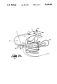
- FIG. 10 is a diagrammatic view illustrating the inner uterine-ring in a functional, open position and in place at the fornix area of the patient;
- FIG. 11 is a fragmentary view, on an enlarged scale, illustrating the outer clamping ring in a clamped position about the inner uterine-ring with a portion of the vaginal canal interposed therebetween;
- FIG. 12 is a perspective view showing the outer uterine-ring in place about the inner uterine-ring with the vaginal canal being clamped therebetween subsequent to circumcision;
- FIG. 13 is a sectional view taken along line 13--13 in FIG. 12, illustrating the relationship between the inner and outer uterine-rings with vaginal tissue therebetween;
- FIG. 14 is a diagrammatic view, similar to FIG. 10, illustrating the insertion of the clamping assembly into the surgically opened abdominal cavity and about the inner uterine-ring with the fornix area of the vagina therebetween.
- FIGS. 1-14 illustrate the hysterectomy surgical device.
- the device includes an inner uterine-ring assembly 100 shown in FIG. 1.
- This assembly 100 comprises an upper handle 110 having a generally C-shaped frame 120 extending therefrom.
- This frame 120 presents a pair of generally horizontal, vertically-displaced struts 122, 124 connected by an integral/curved shank 126.
- the strut/shaft 124 has a distal end 128 with a mounting flange 134 extending therefrom.
- An inner uterine-ring 140 having an annular slot 142 is pivotally mounted to arm 134 by means of at least one pivot pin 144 extending through the ring 140 and into mounting flange 124.
- a linkage arm 160 pivotally mounted to ring 140 by means of pin 163.
- the linkage arm 160 extends along the underside of the shaft 124 as illustrated in FIG. 1.
- a slot 162 extends along the user/proximal end 164 of arm 160.
- the proximal end 164 presents a user-operable handle 165.
- Extending through slot 162 and from shaft 124 is a threaded pin 180 having a knob 182 attached thereto. Threadable movement of knob 182 along the extent of the threaded pin 180 enables pressure to be exerted against the arm 160. This pressure maintains pin 180 at a user-selectable position along the extent of slot 162 and thus maintains the position of ring 140.
- an outer uterine-ring clamp assembly 300 For use with this inner uterine-ring assembly 100 is an outer uterine-ring clamp assembly 300.
- This assembly generally comprises a pair of jaw-like clamps 350, 360.
- Each respective clamp 350, 360 comprises a handle 352, 362 having a generally semi-circular jaw/ring 354, 364 at the distal end thereof.
- the rings 354, 364 form an outer uterine-ring 370 upon drawing the handles 352, 362 together (FIG. 6).
- a threaded pin 390 extends between the proximal ends 359, 369 of each handle 352, 362.
- Wing nut 374 engages the free end of the pin 390 so as to maintain the pin 390 in slot 391 and lateral displacement between the proximal ends of the respective handles 352, 362.
- Pin 380 extends from one of the handles so as to preclude full closure of the jaws 354, 364 which form the outer ring 370.
- the patient In use the patient is positioned in a conventional manner for hysterectomy operations. An incision is made in the abdominal wall 900 according to conventional medical procedure so as to properly expose the reproductive organs, i.e. the uterus 910, which are to be removed. As shown in FIGS. 10 and 14, the uterus 910 and outer vagina wall 920 are exposed to the surgeon.
- the inner uterine-ring assembly 100 is positioned in a collapsed mode for initial insertion into the vagina 920 of the patient.
- the collapsed uterine-ring 140 is generally vertically aligned (FIG. 9) with the vaginal opening 930 so as to enhance this initial penetration.
- the shaft 124 positions the uterine-ring 140 in the vaginal canal at the juncture of the cervix 960 with the vagina identified as the fornix 965.
- the assembly 100 is rotated from a FIG. 9 position to a FIG. 10 position such that the handle 110 is positioned atop the abdominal wall of the patient as shown in FIG. 10.
- the surgeon via linkage arm 140, pivots the ring 140 about 90 degrees from its collapsed position to a functional, generally vertical position as shown in FIG. 10. This position is then maintained by tightening knob 182 so as to bear against the linkage arm 160 as above described.
- the uterine-ring 140 Once the uterine-ring 140 is positioned, it can be further adjusted so that it is placed in the desired position at the fornix 965, i.e. the point at which the surgical circumcision is to be made.
- the protrusion of the cervix 960 into ring 140 delimits further penetration of the ring 140 into the vaginal canal. This position is tactilely sensed by the surgeon.
- the junction 965 of the vagina and uterus is rigidified, supported and exposed to the surgeon. Once so positioned, a rigid, circular area of the vagina is defined and presented to the surgeon.
- the outer clamping assembly 300 is clamped about this uterine-ring 140 with the tissue of the vagina interposed therebetween.
- the respective clamps 350, 360 may be separated to allow for insertion of the semi-circular rings 354, 364 into the abdominal cavity about the vagina and about this inner uterine-ring 140.
- the resulting ring 370 encompasses this inner uterine-ring 140 with hemostatic pressure on the vaginal tissue and surrounding blood vessels therebetween.
- the hemostatic pressure afforded by the resulting ring 370 is controlled by variable displacement of the handles 352, 362 as regulated by the threaded pin 390/wing nut 374 engagement as above described.
- this combination of assemblies 100, 300 presents a guide to the surgeon for scalpel circumcision of the clamped tissue.
- the scalpel (not shown) is drawn about the annular groove 142 of the inner uterine-ring 140 as further guided by the rings 354, 364 embedded therein.
- the uterus 910 is separated from the vagina.
- the pressure of the clamping assembly 300 on the vaginal tissue precludes undesirable bleeding from the surrounding blood vessels and ligaments.
- the surrounding blood vessels, now visible in the sectioned free edge of the vaginal cuff, firmly held in the clamping assembly, are now hemostased with suture or cautery in a conventional manner.
- clamping assembly 300 Once ligated, pressure on the clamping assembly 300 is partially reduced by handle displacement to allow the surgeon to check for undesirable bleeding from the ligated blood vessels and tissues. When all bleeding vessels are completely hemostased the clamping assembly 300 is then removed. The ring 140 of the inner uterine-ring assembly 100 is then positioned in a collapsed mode and removed from the patient. Upon such removal, the free annular end 911 of the vaginal canal are sutured together in a conventional manner. The sutured vaginal walls in turn are sutured to the round ligaments before peritonealization is completed.
- the use of the inner uterine-ring 100/outer uterine ring 3300 combination as above described allows for an effective circumcision of the vaginal tissues. This circumcision presents a free end of the vaginal canal which is easily sewn together in a conventional manner.
- the clamping assembly 300 further allows the surgeon to ensure that there is no undesirable bleeding from the surrounding vessels. Subsequent to such circumcision these vessels ar easily ligated.
Landscapes
- Health & Medical Sciences (AREA)
- Surgery (AREA)
- Life Sciences & Earth Sciences (AREA)
- Heart & Thoracic Surgery (AREA)
- Molecular Biology (AREA)
- Veterinary Medicine (AREA)
- Engineering & Computer Science (AREA)
- Biomedical Technology (AREA)
- Reproductive Health (AREA)
- Medical Informatics (AREA)
- Nuclear Medicine, Radiotherapy & Molecular Imaging (AREA)
- Animal Behavior & Ethology (AREA)
- General Health & Medical Sciences (AREA)
- Public Health (AREA)
- Vascular Medicine (AREA)
- Gynecology & Obstetrics (AREA)
- Pregnancy & Childbirth (AREA)
- Surgical Instruments (AREA)
Abstract
A surgical tool for use in abdominal hysterectomies includes an inner uterine-ring assembly having a ring for insertion into the vagina at the juncture of the cervix and vagina. An outer clamping assembly insertable through a surgically opened abdominal cavity is clamped about the inner ring with the vaginal tissue interposed therebetween. The combination presents a scalpel guide for surgical circumcision of the interposed tissue as well as controls undesirable bleeding from the circumcised tissue.
Description
This invention relates to a surgical device, and more particularly, to a surgical tool for use in performing abdominal hysterectomies.
The basic technique of an abdominal hysterectomy is well known in the medical art. Reference is made to U. S. medical references in which the steps in performing a hysterectomy are set forth therein. One such reference is "An Atlas of Pelvic Operations" published by W. B. Saunders Company and written by Langdon Parsons, M. D. and Howard Ulfelder, M. D. in 1968.
Basically, an incision is made in the abdominal wall and underlying peritoneum so as to expose the abdominal cavity and the various organs therein including the uterus. The uterus is to be removed at its cervical juncture with the vagina commonly referred to as the fornix. Upon identifying such juncture, surrounding blood vessels are ligated and circumcision is made about the vaginal wall at this fornix area. Upon removal of the uterus, the resulting vaginal edges are sewn shut.
Various problems arise in this general operation. The exact location of the vaginal fornix may be difficult to find in some patients. Moreover, constant attention must be made to bleeding due to the surrounding ligaments and blood vessels. Also, a clean, circular incision about the vaginal wall at the fornix may be difficult.
In response thereto I have invented a surgical tool for abdominal hysterectomies which comprises a rigid, inner ring for insertion into the vagina so as to rigidify and define the fornix area from within the vagina. An outer ring is clamped about this inner ring with the vaginal wall therebetween prior to the above circumcision. This rigid ring further presents a guide for scalpel circumcision about the vaginal wall by the surgeon. The clamping assembly precludes undesirable bleeding from the surrounding blood vessels upon circumcision. Subsequent to the circumcision and uterus removal, the blood vessels are then ligated and the clamp easily removed. The resulting annular edge of the vagina is then sutured together.
My surgical device defines a fornix area and provides a rigid guide to the surgeon to allow for a proper vaginal circumcision. Furthermore, undesirable bleeding from the surrounding blood vessels can be controlled due to the relationship between the outer clamping ring and inner ring assemblies.
Accordingly, it is a general object of this invention to provide a surgical tool for use in hysterectomy operations.
Another object of this invention is to provide a surgical tool, as aforesaid, which rigidly defines and outlines the vaginal fornix.
Still another object of this invention is to provide a surgical tool, as aforesaid, which provides a guide to the surgeon for circumcision of the vaginal wall at the fornix area.
Another object of this invention is to provide a surgical tool, as aforesaid, which controls hemostatic pressure and precludes bleeding from surrounding ligaments and blood vessels during and after said circumcision.
Another object of this invention is to provide a surgical tool, as aforesaid, which comprises inner and outer ring assemblies which are easily adaptable for insertion into and withdrawal from a patient.
Other objects and advantages of this invention will become apparent from the following description taken in connection with the accompanying drawings, wherein is set forth by way of illustration and example, an embodiment of this invention.
FIG. 1 is a side elevation view showing the inner uterine-ring assembly in a collapsed position;
FIG. 2 is a bottom plan view, taken along line 2--2 in FIG. 1, illustrating the locking device for holding the inner uterine-ring in position;
FIG. 3 is a fragmentary view illustrating the inner uterine-ring in an open, functional position normal to the collapsed FIG. 1 position;
FIG. 4 is an elevation view, on an enlarged scale, as viewed along line 4--4 in FIG. 3;
FIG. 5 is a sectional view, taken along line 5--5 in FIG. 4, illustrating the pivotal attachments of the inner uterine-ring to the shaft and linkage arm;
FIG. 6 is an elevation view showing the outer clamping assembly;
FIG. 7 is a side elevation view of the outer clamping assembly in FIG. 6;
FIG. 8 is a view of the clamping ring assembly of FIG. 6 and showing the assembly in an exploded mode;
FIG. 9 is a diagrammatic view showing alignment of the inner uterine-ring with the vaginal opening of the patient prior to penetration;
FIG. 10 is a diagrammatic view illustrating the inner uterine-ring in a functional, open position and in place at the fornix area of the patient;
FIG. 11 is a fragmentary view, on an enlarged scale, illustrating the outer clamping ring in a clamped position about the inner uterine-ring with a portion of the vaginal canal interposed therebetween;
FIG. 12 is a perspective view showing the outer uterine-ring in place about the inner uterine-ring with the vaginal canal being clamped therebetween subsequent to circumcision;
FIG. 13 is a sectional view taken along line 13--13 in FIG. 12, illustrating the relationship between the inner and outer uterine-rings with vaginal tissue therebetween; and
FIG. 14 is a diagrammatic view, similar to FIG. 10, illustrating the insertion of the clamping assembly into the surgically opened abdominal cavity and about the inner uterine-ring with the fornix area of the vagina therebetween.
Turning more particularly to the drawings, FIGS. 1-14 illustrate the hysterectomy surgical device. The device includes an inner uterine-ring assembly 100 shown in FIG. 1. This assembly 100 comprises an upper handle 110 having a generally C-shaped frame 120 extending therefrom. This frame 120 presents a pair of generally horizontal, vertically-displaced struts 122, 124 connected by an integral/curved shank 126. The strut/shaft 124 has a distal end 128 with a mounting flange 134 extending therefrom. An inner uterine-ring 140 having an annular slot 142 is pivotally mounted to arm 134 by means of at least one pivot pin 144 extending through the ring 140 and into mounting flange 124.
Extending from the bottom of ring 140 is a linkage arm 160 pivotally mounted to ring 140 by means of pin 163. The linkage arm 160 extends along the underside of the shaft 124 as illustrated in FIG. 1. A slot 162 extends along the user/proximal end 164 of arm 160. The proximal end 164 presents a user-operable handle 165. Extending through slot 162 and from shaft 124 is a threaded pin 180 having a knob 182 attached thereto. Threadable movement of knob 182 along the extent of the threaded pin 180 enables pressure to be exerted against the arm 160. This pressure maintains pin 180 at a user-selectable position along the extent of slot 162 and thus maintains the position of ring 140. Upon displacement of the knob 182 from the arm 160 longitudinal movement of the arm 160 relative to shaft 124 is allowed. The extension of pin 180 through the slot 162 defines the extent of such longitudinal movement and thus the range of pivotal movement of ring 140. As such, the surgeon grasps the handle 165 of the linkage arm 160 and pivots the ring 140 between a collapsed, FIG. 1 position to a functional, FIG. 3 position generally normal to the FIG. 1 position. The ring 140 is then held at either position by exerting pressure of the knob 182 on the arm 160.
For use with this inner uterine-ring assembly 100 is an outer uterine-ring clamp assembly 300. This assembly generally comprises a pair of jaw-like clamps 350, 360. Each respective clamp 350, 360 comprises a handle 352, 362 having a generally semi-circular jaw/ ring 354, 364 at the distal end thereof. Upon interlock between the male 358 and female 368 locking elements the rings 354, 364 form an outer uterine-ring 370 upon drawing the handles 352, 362 together (FIG. 6). A threaded pin 390 extends between the proximal ends 359, 369 of each handle 352, 362. Wing nut 374 engages the free end of the pin 390 so as to maintain the pin 390 in slot 391 and lateral displacement between the proximal ends of the respective handles 352, 362. Pin 380 extends from one of the handles so as to preclude full closure of the jaws 354, 364 which form the outer ring 370.
In use the patient is positioned in a conventional manner for hysterectomy operations. An incision is made in the abdominal wall 900 according to conventional medical procedure so as to properly expose the reproductive organs, i.e. the uterus 910, which are to be removed. As shown in FIGS. 10 and 14, the uterus 910 and outer vagina wall 920 are exposed to the surgeon.
It is recognized that certain conventional surgical steps are first performed in preparation for removing the uterus 910.
As illustrated in FIG. 9, the inner uterine-ring assembly 100 is positioned in a collapsed mode for initial insertion into the vagina 920 of the patient. The collapsed uterine-ring 140 is generally vertically aligned (FIG. 9) with the vaginal opening 930 so as to enhance this initial penetration. Subsequent to insertion, the shaft 124 positions the uterine-ring 140 in the vaginal canal at the juncture of the cervix 960 with the vagina identified as the fornix 965. The assembly 100 is rotated from a FIG. 9 position to a FIG. 10 position such that the handle 110 is positioned atop the abdominal wall of the patient as shown in FIG. 10. The surgeon, via linkage arm 140, pivots the ring 140 about 90 degrees from its collapsed position to a functional, generally vertical position as shown in FIG. 10. This position is then maintained by tightening knob 182 so as to bear against the linkage arm 160 as above described. Once the uterine-ring 140 is positioned, it can be further adjusted so that it is placed in the desired position at the fornix 965, i.e. the point at which the surgical circumcision is to be made. The protrusion of the cervix 960 into ring 140 delimits further penetration of the ring 140 into the vaginal canal. This position is tactilely sensed by the surgeon. Thus, the junction 965 of the vagina and uterus is rigidified, supported and exposed to the surgeon. Once so positioned, a rigid, circular area of the vagina is defined and presented to the surgeon.
Subsequently, after clearance of surrounding ligaments and vessels the outer clamping assembly 300 is clamped about this uterine-ring 140 with the tissue of the vagina interposed therebetween. The respective clamps 350, 360 may be separated to allow for insertion of the semi-circular rings 354, 364 into the abdominal cavity about the vagina and about this inner uterine-ring 140. Upon interlock of mating elements 358, 368 the resulting ring 370 encompasses this inner uterine-ring 140 with hemostatic pressure on the vaginal tissue and surrounding blood vessels therebetween. Thus, the clamped blood vessels need not be cut away as in a normal procedure. The hemostatic pressure afforded by the resulting ring 370 is controlled by variable displacement of the handles 352, 362 as regulated by the threaded pin 390/wing nut 374 engagement as above described.
As shown in FIGS. 11-13, this combination of assemblies 100, 300 presents a guide to the surgeon for scalpel circumcision of the clamped tissue. The scalpel (not shown) is drawn about the annular groove 142 of the inner uterine-ring 140 as further guided by the rings 354, 364 embedded therein. On completion of the circumcision, the uterus 910 is separated from the vagina. The pressure of the clamping assembly 300 on the vaginal tissue precludes undesirable bleeding from the surrounding blood vessels and ligaments. The surrounding blood vessels, now visible in the sectioned free edge of the vaginal cuff, firmly held in the clamping assembly, are now hemostased with suture or cautery in a conventional manner. Once ligated, pressure on the clamping assembly 300 is partially reduced by handle displacement to allow the surgeon to check for undesirable bleeding from the ligated blood vessels and tissues. When all bleeding vessels are completely hemostased the clamping assembly 300 is then removed. The ring 140 of the inner uterine-ring assembly 100 is then positioned in a collapsed mode and removed from the patient. Upon such removal, the free annular end 911 of the vaginal canal are sutured together in a conventional manner. The sutured vaginal walls in turn are sutured to the round ligaments before peritonealization is completed.
The use of the inner uterine-ring 100/outer uterine ring 3300 combination as above described allows for an effective circumcision of the vaginal tissues. This circumcision presents a free end of the vaginal canal which is easily sewn together in a conventional manner. The clamping assembly 300 further allows the surgeon to ensure that there is no undesirable bleeding from the surrounding vessels. Subsequent to such circumcision these vessels ar easily ligated.
It is understood that the details of this hysterectomy operation have not herein been described as is well known by practicing surgeons. Accordingly, I have described the use of my instrument in connection with these well-known surgical procedures in order to advise those skilled in the art as to how my invention is to be utilized.
Although I have presented a preferred embodiment of my invention, it is to be understood that my invention is not to be restricted thereto, except as set forth in the following claims and allowable functional equivalents thereof.
Claims (21)
1. A surgical device for use in performing abdominal hysterectomies comprising:
inner ring means for insertion with a vagina said means comprises:
a ring;
an elongated arm;
means for attaching said ring to said arm, said arm having an end for presenting a handle allowing for user insertion of said ring into said vagina;
clamp means for insertion into an exposed abdominal cavity and about the ring with a portion of said vagina therebetween;
said ring and said clamp means providing a guide for a scalpel for circumcision of said vagina clamped about said ring.
2. The device as set forth in claim 1, wherein said attaching means comprises means for pivotally mounting said ring to an end of said arm.
3. The device as set forth in claim 2, further comprising linkage means for inducing said pivotal movement of said ring by a user.
4. The device as set forth in claim 3, wherein said linkage means comprises:
a second arm;
means for mounting said second arm to said ring, said second arm presenting a user-operable end wherein user movement of said arm end pivots said ring.
5. The device as set forth in claim 4, wherein said ring is pivotal between a first position in which said ring is generally aligned with an opening of said vagina and a second position in which said ring is generally normal to said first position.
6. The device as set forth in claim 5 further comprising locking means for maintaining said second arm and ring in a user-selectable position.
7. The device as set forth in claim 1, wherein said clamp means comprises:
outer ring means having a configuration adapted to fit about said inner ring means;
means for regulating the degree of said fit of said outer ring means about said inner ring means with said vagina clamped therebetween.
8. The device as set forth in claim 7, wherein said outer ring means comprises:
a first element having a ring portion thereon for fitting about said inner ring means;
a second element having a ring portion thereon for fitting about said outer ring means;
means for releasably attaching said first ring element to said second ring element;
said joined elements generally forming a ring circumscribing said inner ring means.
9. The device as set forth in claim 8, wherein said releasable attaching means comprises:
a handle extending from said respective first and second ring elements; and
means for controlling the displacement between said handles, said displacement varying the degree of fit of said ring elements about said inner ring means.
10. The device as set forth in claim 9, wherein said controlling means comprises:
a pin extending between said handles, said pin having at least one free end extending through one of said handles;
fastener means releasably engageable with said pin free end along the length thereof, said engagement precluding movement of said handle towards said free end of said pin, whereby to control said displacement between said handles.
11. The device as set forth in claim 10, wherein said pin is threaded and said fastener means comprises a nut engageable with said threads, said nut releasably engageable along the extent of said pin.
12. A surgical device for use in performing a hysterectomy comprising:
shaft for insertion into a vagina;
a ring element for insertion into said vagina;
means for pivotally mounting said ring to said shaft;
means for user manipulation of said ring between a first position aligning said ring with an opening to said vagina prior to said insertion and a second position generally normal to said first position subsequent to said insertion, said second position of said ring providing a guide for a cutting element for surgical circumcision of vaginal tissue surrounding said ring.
13. The device as set forth in claim 12, wherein said user-manipulation means comprises:
a rod for insertion into said vagina with said shaft;
means for mounting said rod to said ring,
said rod presenting a user-operable end upon said vaginal insertion, whereby movement of said end pivots said ring.
14. The device as set forth in claim 13, further comprising locking means for precluding said rod movement, whereby to maintain said ring in at least one of said positions.
15. The device as set forth in claim 14, wherein said locking means comprises:
a slot at said user-operable end of said rod;
a pin attached to said shaft and extending through said slot;
means for holding said pin at a position along said rod slot, said means precluding relative movement between said rod and said pin.
16. The device as set forth in claim 15, wherein said holding means comprises a fastener releasably engageable with said pin to preclude said relative movement therebetween.
17. The device as set forth in claim 16, wherein said fastener is a nut releasably engageable with threads on said pin.
18. The device as set forth in claim 12 further comprising:
clamping means for engaging said ring with said vagina interposed therebetween,, said clamping means delimiting bleeding from said vagina upon said circumcision.
19. The device as set forth in claim 18, wherein said clamping means comprises:
outer ring means adapted to fit about said ring with said tissue therebetween.
20. The device as set forth in claim 19 wherein said outer ring means comprises jaw means adapted to fit about said inner ring with said tissue therebetween.
21. A surgical device for use in performing abdominal hysterectomies comprising:
clamp means for insertion into an exposed abdominal cavity and about a vagina at a position for subsequent surgical circumcision of said vagina, said clamp means comprising at least one jaw element;
a ring insertable into said vagina for providing a clamping surface, said ring rigidifying said vagina at said position for engagement by said clamp means, said at least one jaw element of said clamp means engaging said ring with said vagina interposed therebetween, said engagement precluding bleeding from said vagina position subsequent to said circumcision.
Priority Applications (1)
| Application Number | Priority Date | Filing Date | Title |
|---|---|---|---|
| US07/511,777 US5108408A (en) | 1990-04-20 | 1990-04-20 | Uterine-ring hysterectomy clamp |
Applications Claiming Priority (1)
| Application Number | Priority Date | Filing Date | Title |
|---|---|---|---|
| US07/511,777 US5108408A (en) | 1990-04-20 | 1990-04-20 | Uterine-ring hysterectomy clamp |
Publications (1)
| Publication Number | Publication Date |
|---|---|
| US5108408A true US5108408A (en) | 1992-04-28 |
Family
ID=24036397
Family Applications (1)
| Application Number | Title | Priority Date | Filing Date |
|---|---|---|---|
| US07/511,777 Expired - Fee Related US5108408A (en) | 1990-04-20 | 1990-04-20 | Uterine-ring hysterectomy clamp |
Country Status (1)
| Country | Link |
|---|---|
| US (1) | US5108408A (en) |
Cited By (51)
| Publication number | Priority date | Publication date | Assignee | Title |
|---|---|---|---|---|
| US5241969A (en) * | 1992-06-10 | 1993-09-07 | Carson Jay W | Controlled and safe fine needle aspiration device |
| EP0597471A1 (en) * | 1992-11-12 | 1994-05-18 | Karl Storz GmbH & Co. | Trocar sleeve |
| FR2697989A1 (en) * | 1992-11-19 | 1994-05-20 | Hourcabie Jacques | Device for presenting and maintaining organs for pereloscopic hysterectomy. |
| EP0726727A1 (en) * | 1993-10-22 | 1996-08-21 | McCartney, Anthony John | Transvaginal tube as an aid to laparoscopic surgery |
| US5950789A (en) * | 1998-04-27 | 1999-09-14 | Caterpillar Inc. | End of fill detector for a fluid actuated clutch |
| US5980534A (en) * | 1998-10-07 | 1999-11-09 | Gimpelson; Richard J. | Cervical clamp |
| US20020111562A1 (en) * | 1999-11-23 | 2002-08-15 | Richards Michael Owen | Cellular collection apparatus and method |
| US20020183771A1 (en) * | 2001-03-28 | 2002-12-05 | Vascular Control Systems, Inc. | Method and apparatus for the detection and ligation of uterine arteries |
| US6550482B1 (en) * | 2000-04-21 | 2003-04-22 | Vascular Control Systems, Inc. | Methods for non-permanent occlusion of a uterine artery |
| US6572631B1 (en) | 1993-10-22 | 2003-06-03 | Gynetech Pty Ltd. | Transvaginal tube as an aid to laparoscopic surgery |
| US20030120306A1 (en) * | 2000-04-21 | 2003-06-26 | Vascular Control System | Method and apparatus for the detection and occlusion of blood vessels |
| US20030120286A1 (en) * | 2001-03-28 | 2003-06-26 | Vascular Control System | Luminal clip applicator with sensor |
| US6602251B2 (en) | 1998-12-08 | 2003-08-05 | Vascular Control Systems, Inc. | Device and methods for occlusion of the uterine artieries |
| US20030191391A1 (en) * | 2002-04-04 | 2003-10-09 | Burbank Fred H. | Doppler directed suturing and compression device and method |
| US6635065B2 (en) | 2000-11-16 | 2003-10-21 | Vascular Control Systems, Inc. | Doppler directed suture ligation device and method |
| US6638286B1 (en) | 2000-11-16 | 2003-10-28 | Vascular Control Systems, Inc. | Doppler directed suture ligation device and method |
| US20040092979A1 (en) * | 2001-03-28 | 2004-05-13 | Vascular Control System | Occlusion device with deployable paddles for detection and occlusion of blood vessels |
| US20040097962A1 (en) * | 2002-11-19 | 2004-05-20 | Vascular Control System | Deployable constrictor for uterine artery occlusion |
| US20040097961A1 (en) * | 2002-11-19 | 2004-05-20 | Vascular Control System | Tenaculum for use with occlusion devices |
| US6743251B1 (en) | 2000-11-15 | 2004-06-01 | Scimed Life Systems, Inc. | Implantable devices with polymeric detachment junction |
| US20040153105A1 (en) * | 2003-01-30 | 2004-08-05 | Vascular Control Systems, Inc. | Uterine artery occlusion clamp |
| US20040202694A1 (en) * | 2003-04-11 | 2004-10-14 | Vascular Control Systems, Inc. | Embolic occlusion of uterine arteries |
| US20050021049A1 (en) * | 2002-11-13 | 2005-01-27 | Welch Robert A. | Incompetent cervix aide |
| US20050101974A1 (en) * | 2003-02-05 | 2005-05-12 | Vascular Control Systems, Inc. | Vascular clamp for caesarian section |
| US20050107818A1 (en) * | 2003-11-17 | 2005-05-19 | Valtchev Konstantin L. | Vaginal delineation and occlusion device |
| US20050113852A1 (en) * | 2003-11-20 | 2005-05-26 | Vascular Control Systems, Inc. | Uterine artery occlusion device with cervical receptacle |
| US20050113634A1 (en) * | 2003-11-25 | 2005-05-26 | Vascular Control Systems, Inc. | Occlusion device for asymmetrical uterine artery anatomy |
| US20060106109A1 (en) * | 2004-10-27 | 2006-05-18 | Burbank Fred H | Short term treatment for uterine disorder |
| US20060241337A1 (en) * | 2003-03-28 | 2006-10-26 | Vascular Control Systems, Inc. | Uterine tissue monitoring device and method |
| US20060271037A1 (en) * | 2005-05-25 | 2006-11-30 | Forcept, Inc. | Assisted systems and methods for performing transvaginal hysterectomies |
| US20070027450A1 (en) * | 2005-07-28 | 2007-02-01 | Forcept, Inc. | Devices and methods for mobilization of the uterus |
| US20070049973A1 (en) * | 2005-08-29 | 2007-03-01 | Vascular Control Systems, Inc. | Method and device for treating adenomyosis and endometriosis |
| US7223279B2 (en) | 2000-04-21 | 2007-05-29 | Vascular Control Systems, Inc. | Methods for minimally-invasive, non-permanent occlusion of a uterine artery |
| US20070129726A1 (en) * | 2005-05-12 | 2007-06-07 | Eder Joseph C | Electrocautery method and apparatus |
| US20080200939A1 (en) * | 2007-02-20 | 2008-08-21 | Maclean Brian | Laparoscopic tourniquet |
| US20080221565A1 (en) * | 2005-05-12 | 2008-09-11 | Joseph Charles Eder | Electrocautery method and apparatus |
| WO2009022326A1 (en) * | 2007-08-15 | 2009-02-19 | Easynotes Ltd. | Hysterectomy ring |
| US20090198272A1 (en) * | 2008-02-06 | 2009-08-06 | Lawrence Kerver | Method and apparatus for articulating the wrist of a laparoscopic grasping instrument |
| US20110184404A1 (en) * | 2006-05-02 | 2011-07-28 | Erik Walberg | Laparoscopic radiofrequency surgical device |
| US20110202058A1 (en) * | 2005-05-12 | 2011-08-18 | Joseph Eder | Apparatus for Tissue Cauterization |
| US20110230875A1 (en) * | 2008-02-06 | 2011-09-22 | Erik Walberg | Articulable electrosurgical instrument with a stabilizable articulation actuator |
| US20110238062A1 (en) * | 2010-03-26 | 2011-09-29 | Tim Koss | Impedance Mediated Power Delivery for Electrosurgery |
| US20110238056A1 (en) * | 2010-03-26 | 2011-09-29 | Tim Koss | Impedance mediated control of power delivery for electrosurgery |
| US8323278B2 (en) | 2010-12-06 | 2012-12-04 | Soulor Surgical, Inc. | Apparatus for treating a portion of a reproductive system and related methods of use |
| US8574229B2 (en) | 2006-05-02 | 2013-11-05 | Aesculap Ag | Surgical tool |
| US8728072B2 (en) | 2005-05-12 | 2014-05-20 | Aesculap Ag | Electrocautery method and apparatus |
| US9173698B2 (en) | 2010-09-17 | 2015-11-03 | Aesculap Ag | Electrosurgical tissue sealing augmented with a seal-enhancing composition |
| US9339327B2 (en) | 2011-06-28 | 2016-05-17 | Aesculap Ag | Electrosurgical tissue dissecting device |
| WO2017123891A1 (en) * | 2016-01-13 | 2017-07-20 | Memorial Sloan-Kettering Cancer Center | Uterine manipulator arrangement |
| US9872724B2 (en) | 2012-09-26 | 2018-01-23 | Aesculap Ag | Apparatus for tissue cutting and sealing |
| US11278321B2 (en) * | 2014-03-14 | 2022-03-22 | The University Of Liverpool | Device for compressing the uterus |
Citations (7)
| Publication number | Priority date | Publication date | Assignee | Title |
|---|---|---|---|---|
| US183602A (en) * | 1876-10-24 | Improvement in surgical clamps | ||
| US3707970A (en) * | 1970-05-04 | 1973-01-02 | Vseojuzny Nii Khirurgicheskoi | Surgical instrument for hysterectomy |
| US4000743A (en) * | 1975-07-09 | 1977-01-04 | Kenneth Weaver | Uterine anteverter |
| US4022208A (en) * | 1974-07-25 | 1977-05-10 | Valtchev Konstantin L | Gynecologic instrument |
| US4491136A (en) * | 1973-03-05 | 1985-01-01 | Leveen Harry H | Disposable circumcision device |
| US4644953A (en) * | 1983-09-13 | 1987-02-24 | Fritz Gegauf AG Bernina Nahmaschinen Fabrik | Surgical instrument, more particularly hysterectomium |
| EP0319394A1 (en) * | 1987-11-30 | 1989-06-07 | Milos Sovak | Hysterography device |
-
1990
- 1990-04-20 US US07/511,777 patent/US5108408A/en not_active Expired - Fee Related
Patent Citations (7)
| Publication number | Priority date | Publication date | Assignee | Title |
|---|---|---|---|---|
| US183602A (en) * | 1876-10-24 | Improvement in surgical clamps | ||
| US3707970A (en) * | 1970-05-04 | 1973-01-02 | Vseojuzny Nii Khirurgicheskoi | Surgical instrument for hysterectomy |
| US4491136A (en) * | 1973-03-05 | 1985-01-01 | Leveen Harry H | Disposable circumcision device |
| US4022208A (en) * | 1974-07-25 | 1977-05-10 | Valtchev Konstantin L | Gynecologic instrument |
| US4000743A (en) * | 1975-07-09 | 1977-01-04 | Kenneth Weaver | Uterine anteverter |
| US4644953A (en) * | 1983-09-13 | 1987-02-24 | Fritz Gegauf AG Bernina Nahmaschinen Fabrik | Surgical instrument, more particularly hysterectomium |
| EP0319394A1 (en) * | 1987-11-30 | 1989-06-07 | Milos Sovak | Hysterography device |
Non-Patent Citations (2)
| Title |
|---|
| "An Atlas of Pelvic Operations", pp. 8-39, Langdon Parsons, M.D. and Howard Ulfelder, M.D. |
| An Atlas of Pelvic Operations , pp. 8 39, Langdon Parsons, M.D. and Howard Ulfelder, M.D. * |
Cited By (108)
| Publication number | Priority date | Publication date | Assignee | Title |
|---|---|---|---|---|
| US5241969A (en) * | 1992-06-10 | 1993-09-07 | Carson Jay W | Controlled and safe fine needle aspiration device |
| EP0597471A1 (en) * | 1992-11-12 | 1994-05-18 | Karl Storz GmbH & Co. | Trocar sleeve |
| FR2697989A1 (en) * | 1992-11-19 | 1994-05-20 | Hourcabie Jacques | Device for presenting and maintaining organs for pereloscopic hysterectomy. |
| WO1994010926A1 (en) * | 1992-11-19 | 1994-05-26 | Jacques Alain Hourcabie | Organ presenting and holding apparatus for celioscopic hysterectomy |
| US6572631B1 (en) | 1993-10-22 | 2003-06-03 | Gynetech Pty Ltd. | Transvaginal tube as an aid to laparoscopic surgery |
| EP0726727A1 (en) * | 1993-10-22 | 1996-08-21 | McCartney, Anthony John | Transvaginal tube as an aid to laparoscopic surgery |
| EP0726727A4 (en) * | 1993-10-22 | 1997-05-02 | Anthony John Mccartney | Transvaginal tube as an aid to laparoscopic surgery |
| US20070112356A1 (en) * | 1993-10-22 | 2007-05-17 | Gynetech Pty Ltd | Transvaginal tube as an aid to laparoscopic surgery |
| US20050261714A1 (en) * | 1993-10-22 | 2005-11-24 | Mccartney Anthony J | Transvaginal tube as an aid to laparoscopic surgery |
| US8082925B2 (en) | 1993-10-22 | 2011-12-27 | Gynetech Pty Ltd. | Transvaginal tube as an aid to laparoscopic surgery |
| US5950789A (en) * | 1998-04-27 | 1999-09-14 | Caterpillar Inc. | End of fill detector for a fluid actuated clutch |
| US5980534A (en) * | 1998-10-07 | 1999-11-09 | Gimpelson; Richard J. | Cervical clamp |
| US6764488B1 (en) | 1998-12-08 | 2004-07-20 | Vascular Control Systems, Inc. | Devices and methods for occlusion of the uterine arteries |
| US20030216759A1 (en) * | 1998-12-08 | 2003-11-20 | Vascular Control Systems, Inc. | Devices and methods for occlusion of the uterine arteries |
| US7771357B2 (en) | 1998-12-08 | 2010-08-10 | Vascular Control Systems, Inc. | Devices and methods for occlusion of the uterine arteries |
| US6602251B2 (en) | 1998-12-08 | 2003-08-05 | Vascular Control Systems, Inc. | Device and methods for occlusion of the uterine artieries |
| US20020111562A1 (en) * | 1999-11-23 | 2002-08-15 | Richards Michael Owen | Cellular collection apparatus and method |
| US6926677B2 (en) * | 1999-11-23 | 2005-08-09 | Michael Owen Richards | Cellular collection apparatus and method |
| US20030120306A1 (en) * | 2000-04-21 | 2003-06-26 | Vascular Control System | Method and apparatus for the detection and occlusion of blood vessels |
| US6550482B1 (en) * | 2000-04-21 | 2003-04-22 | Vascular Control Systems, Inc. | Methods for non-permanent occlusion of a uterine artery |
| US7223279B2 (en) | 2000-04-21 | 2007-05-29 | Vascular Control Systems, Inc. | Methods for minimally-invasive, non-permanent occlusion of a uterine artery |
| US20070203505A1 (en) * | 2000-04-21 | 2007-08-30 | Fred Burbank | Methods for minimally invasive, non-permanent occlusion of a uterine artery |
| US20080200924A1 (en) * | 2000-04-21 | 2008-08-21 | Vascular Control Systems, Inc. | Methods for minimally invasive, non-permanent occlusion of a uterine artery |
| US6743251B1 (en) | 2000-11-15 | 2004-06-01 | Scimed Life Systems, Inc. | Implantable devices with polymeric detachment junction |
| US20040220563A1 (en) * | 2000-11-15 | 2004-11-04 | Scimed Life Systems, Inc. | Implantable devices with polymeric detachment junction |
| US20040059352A1 (en) * | 2000-11-16 | 2004-03-25 | Vascular Control Systems, Inc. | Doppler directed suture ligation device and method |
| US6638286B1 (en) | 2000-11-16 | 2003-10-28 | Vascular Control Systems, Inc. | Doppler directed suture ligation device and method |
| US6635065B2 (en) | 2000-11-16 | 2003-10-21 | Vascular Control Systems, Inc. | Doppler directed suture ligation device and method |
| US7141057B2 (en) | 2000-11-16 | 2006-11-28 | Vascular Control Systems, Inc. | Doppler directed suture ligation device and method |
| US7354444B2 (en) | 2001-03-28 | 2008-04-08 | Vascular Control Systems, Inc. | Occlusion device with deployable paddles for detection and occlusion of blood vessels |
| US20040092979A1 (en) * | 2001-03-28 | 2004-05-13 | Vascular Control System | Occlusion device with deployable paddles for detection and occlusion of blood vessels |
| US20030120286A1 (en) * | 2001-03-28 | 2003-06-26 | Vascular Control System | Luminal clip applicator with sensor |
| US20090287088A1 (en) * | 2001-03-28 | 2009-11-19 | Vascular Control Systems, Inc. | Luminal clip applicator with sensor and methods for occluding body lumens |
| US7594890B2 (en) | 2001-03-28 | 2009-09-29 | Vascular Control System, Inc. | Multi-axial uterine artery identification, characterization, and occlusion devices |
| US6905506B2 (en) | 2001-03-28 | 2005-06-14 | Vascular Control Systems, Inc. | Multi-axial uterine artery identification, characterization, and occlusion pivoting devices and methods |
| US7229465B2 (en) | 2001-03-28 | 2007-06-12 | Vascular Control Systems, Inc. | Method and apparatus for the detection and ligation of uterine arteries |
| US20020183771A1 (en) * | 2001-03-28 | 2002-12-05 | Vascular Control Systems, Inc. | Method and apparatus for the detection and ligation of uterine arteries |
| US20050228416A1 (en) * | 2001-03-28 | 2005-10-13 | Vascular Control Systems, Inc. | Multi-axial uterine artery identification, characterization, and occlusion pivoting devices and methods |
| US20020188306A1 (en) * | 2001-03-28 | 2002-12-12 | Burbank Fred H. | Multi-axial uterine artery identification, characterization, and occlusion pivoting devices and methods |
| US20060074328A1 (en) * | 2002-04-04 | 2006-04-06 | Vascular Control Systems, Inc. | Doppler directed suturing and compression device and method |
| US7645284B2 (en) | 2002-04-04 | 2010-01-12 | Vascular Control Systems, Inc. | Doppler directed suturing and compression device and method |
| US20030191391A1 (en) * | 2002-04-04 | 2003-10-09 | Burbank Fred H. | Doppler directed suturing and compression device and method |
| US7207996B2 (en) | 2002-04-04 | 2007-04-24 | Vascular Control Systems, Inc. | Doppler directed suturing and compression device and method |
| AU2002323033B2 (en) * | 2002-04-11 | 2007-10-18 | Michael Owen Richards | Cellular collection apparatus and method |
| US6905472B2 (en) | 2002-11-13 | 2005-06-14 | Robert A. Welch | Incompetent cervix aide |
| US7153280B2 (en) | 2002-11-13 | 2006-12-26 | Welch Robert A | Incompetent cervix aide |
| US20050021049A1 (en) * | 2002-11-13 | 2005-01-27 | Welch Robert A. | Incompetent cervix aide |
| US7172603B2 (en) | 2002-11-19 | 2007-02-06 | Vascular Control Systems, Inc. | Deployable constrictor for uterine artery occlusion |
| US20040097962A1 (en) * | 2002-11-19 | 2004-05-20 | Vascular Control System | Deployable constrictor for uterine artery occlusion |
| US20040097961A1 (en) * | 2002-11-19 | 2004-05-20 | Vascular Control System | Tenaculum for use with occlusion devices |
| US7479145B2 (en) | 2002-11-19 | 2009-01-20 | Vascular Control Systems, Inc. | Tenaculum-like device for intravaginal instrument delivery |
| US20070173863A1 (en) * | 2002-11-19 | 2007-07-26 | Vascular Control Systems, Inc. | Deployable constrictor for uterine artery occlusion |
| US20040153105A1 (en) * | 2003-01-30 | 2004-08-05 | Vascular Control Systems, Inc. | Uterine artery occlusion clamp |
| US20080097473A1 (en) * | 2003-01-30 | 2008-04-24 | Vascular Control Systems, Inc. | Treatment for post partum hemorrhage |
| US7404821B2 (en) | 2003-01-30 | 2008-07-29 | Vascular Control Systems, Inc. | Treatment for post partum hemorrhage |
| US7329265B2 (en) | 2003-01-30 | 2008-02-12 | Vascular Control Systems, Inc. | Uterine artery occlusion clamp |
| US20050101974A1 (en) * | 2003-02-05 | 2005-05-12 | Vascular Control Systems, Inc. | Vascular clamp for caesarian section |
| US7651511B2 (en) * | 2003-02-05 | 2010-01-26 | Vascular Control Systems, Inc. | Vascular clamp for caesarian section |
| US7616979B2 (en) | 2003-03-28 | 2009-11-10 | Vascular Control Systems, Inc. | Uterine tissue monitoring device and method |
| US7333844B2 (en) | 2003-03-28 | 2008-02-19 | Vascular Control Systems, Inc. | Uterine tissue monitoring device and method |
| US20060241337A1 (en) * | 2003-03-28 | 2006-10-26 | Vascular Control Systems, Inc. | Uterine tissue monitoring device and method |
| US20040202694A1 (en) * | 2003-04-11 | 2004-10-14 | Vascular Control Systems, Inc. | Embolic occlusion of uterine arteries |
| US20050107818A1 (en) * | 2003-11-17 | 2005-05-19 | Valtchev Konstantin L. | Vaginal delineation and occlusion device |
| US20050113852A1 (en) * | 2003-11-20 | 2005-05-26 | Vascular Control Systems, Inc. | Uterine artery occlusion device with cervical receptacle |
| US7325546B2 (en) | 2003-11-20 | 2008-02-05 | Vascular Control Systems, Inc. | Uterine artery occlusion device with cervical receptacle |
| US7686817B2 (en) | 2003-11-25 | 2010-03-30 | Vascular Control Systems, Inc. | Occlusion device for asymmetrical uterine artery anatomy |
| US20050113634A1 (en) * | 2003-11-25 | 2005-05-26 | Vascular Control Systems, Inc. | Occlusion device for asymmetrical uterine artery anatomy |
| US7875036B2 (en) | 2004-10-27 | 2011-01-25 | Vascular Control Systems, Inc. | Short term treatment for uterine disorder |
| US20060106109A1 (en) * | 2004-10-27 | 2006-05-18 | Burbank Fred H | Short term treatment for uterine disorder |
| US8728072B2 (en) | 2005-05-12 | 2014-05-20 | Aesculap Ag | Electrocautery method and apparatus |
| US8696662B2 (en) | 2005-05-12 | 2014-04-15 | Aesculap Ag | Electrocautery method and apparatus |
| US9339323B2 (en) | 2005-05-12 | 2016-05-17 | Aesculap Ag | Electrocautery method and apparatus |
| US8888770B2 (en) | 2005-05-12 | 2014-11-18 | Aesculap Ag | Apparatus for tissue cauterization |
| US20080221565A1 (en) * | 2005-05-12 | 2008-09-11 | Joseph Charles Eder | Electrocautery method and apparatus |
| US10314642B2 (en) | 2005-05-12 | 2019-06-11 | Aesculap Ag | Electrocautery method and apparatus |
| US20110202058A1 (en) * | 2005-05-12 | 2011-08-18 | Joseph Eder | Apparatus for Tissue Cauterization |
| US20070129726A1 (en) * | 2005-05-12 | 2007-06-07 | Eder Joseph C | Electrocautery method and apparatus |
| US20060271037A1 (en) * | 2005-05-25 | 2006-11-30 | Forcept, Inc. | Assisted systems and methods for performing transvaginal hysterectomies |
| US20070027450A1 (en) * | 2005-07-28 | 2007-02-01 | Forcept, Inc. | Devices and methods for mobilization of the uterus |
| US7641651B2 (en) | 2005-07-28 | 2010-01-05 | Aragon Surgical, Inc. | Devices and methods for mobilization of the uterus |
| US20070049973A1 (en) * | 2005-08-29 | 2007-03-01 | Vascular Control Systems, Inc. | Method and device for treating adenomyosis and endometriosis |
| US20110184404A1 (en) * | 2006-05-02 | 2011-07-28 | Erik Walberg | Laparoscopic radiofrequency surgical device |
| US9918778B2 (en) | 2006-05-02 | 2018-03-20 | Aesculap Ag | Laparoscopic radiofrequency surgical device |
| US11058478B2 (en) | 2006-05-02 | 2021-07-13 | Aesculap Ag | Laparoscopic radiofrequency surgical device |
| US8574229B2 (en) | 2006-05-02 | 2013-11-05 | Aesculap Ag | Surgical tool |
| US20080200939A1 (en) * | 2007-02-20 | 2008-08-21 | Maclean Brian | Laparoscopic tourniquet |
| WO2009022326A1 (en) * | 2007-08-15 | 2009-02-19 | Easynotes Ltd. | Hysterectomy ring |
| US8454626B2 (en) | 2007-08-15 | 2013-06-04 | Ilan Calderon | Hysterectomy ring |
| US20110230875A1 (en) * | 2008-02-06 | 2011-09-22 | Erik Walberg | Articulable electrosurgical instrument with a stabilizable articulation actuator |
| US8870867B2 (en) | 2008-02-06 | 2014-10-28 | Aesculap Ag | Articulable electrosurgical instrument with a stabilizable articulation actuator |
| US20090198272A1 (en) * | 2008-02-06 | 2009-08-06 | Lawrence Kerver | Method and apparatus for articulating the wrist of a laparoscopic grasping instrument |
| US20110238056A1 (en) * | 2010-03-26 | 2011-09-29 | Tim Koss | Impedance mediated control of power delivery for electrosurgery |
| US8827992B2 (en) | 2010-03-26 | 2014-09-09 | Aesculap Ag | Impedance mediated control of power delivery for electrosurgery |
| US8419727B2 (en) | 2010-03-26 | 2013-04-16 | Aesculap Ag | Impedance mediated power delivery for electrosurgery |
| US9277962B2 (en) | 2010-03-26 | 2016-03-08 | Aesculap Ag | Impedance mediated control of power delivery for electrosurgery |
| US20110238062A1 (en) * | 2010-03-26 | 2011-09-29 | Tim Koss | Impedance Mediated Power Delivery for Electrosurgery |
| US10130411B2 (en) | 2010-03-26 | 2018-11-20 | Aesculap Ag | Impedance mediated control of power delivery for electrosurgery |
| US9173698B2 (en) | 2010-09-17 | 2015-11-03 | Aesculap Ag | Electrosurgical tissue sealing augmented with a seal-enhancing composition |
| US10034687B2 (en) | 2010-12-06 | 2018-07-31 | Surgigyn, Inc. | Apparatus for treating a portion of a reproductive system and related methods of use |
| US8608738B2 (en) | 2010-12-06 | 2013-12-17 | Soulor Surgical, Inc. | Apparatus for treating a portion of a reproductive system and related methods of use |
| US8323278B2 (en) | 2010-12-06 | 2012-12-04 | Soulor Surgical, Inc. | Apparatus for treating a portion of a reproductive system and related methods of use |
| US11627990B2 (en) | 2010-12-06 | 2023-04-18 | Gyrus Acmi, Inc. | Apparatus for treating a portion of a reproductive system and related methods of use |
| US10004555B2 (en) | 2011-06-28 | 2018-06-26 | Aesculap Ag | Electrosurgical tissue dissecting device |
| US9339327B2 (en) | 2011-06-28 | 2016-05-17 | Aesculap Ag | Electrosurgical tissue dissecting device |
| US9872724B2 (en) | 2012-09-26 | 2018-01-23 | Aesculap Ag | Apparatus for tissue cutting and sealing |
| US11278321B2 (en) * | 2014-03-14 | 2022-03-22 | The University Of Liverpool | Device for compressing the uterus |
| WO2017123891A1 (en) * | 2016-01-13 | 2017-07-20 | Memorial Sloan-Kettering Cancer Center | Uterine manipulator arrangement |
| US11607249B2 (en) | 2016-01-13 | 2023-03-21 | Memorial Sloan Kettering-Cancer Center | Uterine manipulator arrangement |
Similar Documents
| Publication | Publication Date | Title |
|---|---|---|
| US5108408A (en) | Uterine-ring hysterectomy clamp | |
| US5993385A (en) | Self-aligning side-loading surgical retractor | |
| US4596249A (en) | Implement for setting sutures | |
| US5562680A (en) | Apparatus for assisting the performance of pelvic endoscopic procedures | |
| US6976992B2 (en) | Dual-function medical instrument | |
| EP1175179B1 (en) | A surgical forceps | |
| US5201752A (en) | Cholecystectomy dissector instrument | |
| US3783873A (en) | Weighted surgical clamp having foldable prop | |
| US7479145B2 (en) | Tenaculum-like device for intravaginal instrument delivery | |
| US5328077A (en) | Method and apparatus for treating female urinary incontinence | |
| US4428571A (en) | Limb positioning device | |
| US5007920A (en) | Tendon sectioning support clamp | |
| US5843099A (en) | Single system ligature carrier and tissue clamp for sacrospinous colpopexy | |
| US5383477A (en) | Method and apparatus for laparoscopic repair of hernias | |
| US8603130B2 (en) | Instrument for engaging a body structure | |
| EP0786962A1 (en) | Vaginal extender for colpotomy surgery | |
| US20070238933A1 (en) | Posterior approach retractor ring and attachments system | |
| CN210354790U (en) | A fixed bolster for department of general surgery's operation | |
| WO2011140604A1 (en) | A uterine manipulator | |
| US20050192484A1 (en) | Retractor blades for minimally invasive surgical procedures and method of retraction | |
| WO1996002197A1 (en) | Instrument for gynaecological surgery in women | |
| US6409731B1 (en) | Bone leveler apparatus | |
| US3716056A (en) | Vasectomy procedure and instrument for use therewith | |
| EP3092954A1 (en) | Devices for ligating uterine arteries | |
| US20040225197A1 (en) | Surgical retractor |
Legal Events
| Date | Code | Title | Description |
|---|---|---|---|
| CC | Certificate of correction | ||
| REMI | Maintenance fee reminder mailed | ||
| LAPS | Lapse for failure to pay maintenance fees | ||
| FP | Lapsed due to failure to pay maintenance fee |
Effective date: 19960501 |
|
| STCH | Information on status: patent discontinuation |
Free format text: PATENT EXPIRED DUE TO NONPAYMENT OF MAINTENANCE FEES UNDER 37 CFR 1.362 |