US5111341A - Drive device for truck mirror - Google Patents
Drive device for truck mirror Download PDFInfo
- Publication number
- US5111341A US5111341A US07/567,103 US56710390A US5111341A US 5111341 A US5111341 A US 5111341A US 56710390 A US56710390 A US 56710390A US 5111341 A US5111341 A US 5111341A
- Authority
- US
- United States
- Prior art keywords
- mirror
- shaft
- block
- casing
- rotation
- Prior art date
- Legal status (The legal status is an assumption and is not a legal conclusion. Google has not performed a legal analysis and makes no representation as to the accuracy of the status listed.)
- Expired - Fee Related
Links
Images

Classifications
-
- B—PERFORMING OPERATIONS; TRANSPORTING
- B60—VEHICLES IN GENERAL
- B60R—VEHICLES, VEHICLE FITTINGS, OR VEHICLE PARTS, NOT OTHERWISE PROVIDED FOR
- B60R1/00—Optical viewing arrangements; Real-time viewing arrangements for drivers or passengers using optical image capturing systems, e.g. cameras or video systems specially adapted for use in or on vehicles
- B60R1/02—Rear-view mirror arrangements
- B60R1/06—Rear-view mirror arrangements mounted on vehicle exterior
- B60R1/0605—Rear-view mirror arrangements mounted on vehicle exterior specially adapted for mounting on trucks, e.g. by C-shaped support means
- B60R1/0607—Rear-view mirror arrangements mounted on vehicle exterior specially adapted for mounting on trucks, e.g. by C-shaped support means with remote position control adjustment
- B60R1/0612—Rear-view mirror arrangements mounted on vehicle exterior specially adapted for mounting on trucks, e.g. by C-shaped support means with remote position control adjustment by electrically actuated means
-
- Y—GENERAL TAGGING OF NEW TECHNOLOGICAL DEVELOPMENTS; GENERAL TAGGING OF CROSS-SECTIONAL TECHNOLOGIES SPANNING OVER SEVERAL SECTIONS OF THE IPC; TECHNICAL SUBJECTS COVERED BY FORMER USPC CROSS-REFERENCE ART COLLECTIONS [XRACs] AND DIGESTS
- Y10—TECHNICAL SUBJECTS COVERED BY FORMER USPC
- Y10S—TECHNICAL SUBJECTS COVERED BY FORMER USPC CROSS-REFERENCE ART COLLECTIONS [XRACs] AND DIGESTS
- Y10S359/00—Optical: systems and elements
- Y10S359/90—Methods
Definitions
- This invention relates to a mirror turning device, and in particular to a device for turning the exterior mirror on an automotive vehicle.
- the device of the present invention was specifically designed for use on trucks, it will be appreciated that the device could also be used on passenger vehicles having large exterior mirrors of the type used when towing a boat or trailer.
- the object of the present invention is to overcome the above defined disadvantages by providing a relatively simple mirror turning device, which can be attached to an existing mirror bracket, and which prevents mirror rotation beyond predetermined limits.
- the present invention relates to a device for turning the exterior mirror of an automotive vehicle comprising pivot means for rotatably supporting one end of the mirror; casing means for mounting on one end of the mirror; elongated, threaded shaft means in said casing means; drive means for rotating said shaft means in either direction; block means slidable on said shaft means for longitudinal movement therealong when said shaft means is rotated; arm means pivotally connected at one end to said block means and fixedly connected to said other end of the mirror for rotating the latter when rotation of the shaft means causes longitudinal movement of the block means and rotation of the arm means; and switch means in said casing means for limiting rotation of the arm means and consequently of the mirror carried connected thereto.
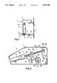
- FIG. 1 is a schematic, end elevation view of a truck mirror with a device in accordance with the present invention connected thereto;
- FIG. 2 is a cross-sectional view of the device of FIG. 1;
- FIG. 3 is a longitudinal sectional view of one end of the device of FIGS. 1 and 2;
- FIG. 4 is an exploded, schematic, perspective view of an arm used in the device of FIGS. 1 to 3.
- the mirror turning device of the present invention which is generally indicated at 1 is used to rotate a conventional truck mirror 2.
- the casing 3 of the device 1 is connected to a bar of a conventional mirror bracket (not shown), which is mounted on the side of a truck or other vehicle.
- a pair of arms 6 and 7 extend outwardly from the bracket arm 5.
- the lower arm 6 carries a bar 9, which rotatably act as a pivot for supporting the bottom end of the mirror 2.
- the bar 9 is connected to the arm 6 by a bolt 10 and nut 11, and to the bolt 13 extending downwardly from the bottom centre of the mirror 2 by nuts 14 and washers 15.
- the bolt 16 at the top end of the mirror 2 is connected to the device 1 for rotation thereby.
- the device 1 includes the casing 3, which contains a reversible motor 17 and a gearbox 18 for rotating an elongated, threaded shaft 20.
- One end of the shaft 20 is connected to the drive shaft 21 extending out of the gearbox 18 by a flexible coupling defined by a sleeve 22 and hose clamps 24.
- the other end 25 of the shaft 20 extends into a bearing 26 mounted in a plate 28 extending upwardly from the bottom wall 29 of the casing 3.
- the shaft 20 carries a block 30, which is internally threaded for movement along the shaft 20 when the latter is rotated by the motor 17 and gearbox 18 combination. Movement of the block 30 in either direction is limited by a pair of microswitches 31, the actuator fingers 32 of which extend into the path of travel of the outer end of the block 30.
- a pin 33 extends upwardly from the block 30 through a longitudinal extending slot 34 (FIGS. 2 and 4) in one end of a lever 35.
- the lever 35 forms part of an arm, which includes a cup-shaped sleeve 36 mounted in the casing 3 above the bolt 16.
- the bolt 16 extends upwardly through a nut 37 and a washer 38 beneath the casing 3, and through a neck 40 (FIGS.
- a nut 42 and a washer 43 secure the bolt 16 to the sleeve 36.
- a narrow neck 45 at the top end of the sleeve 36 extends upwardly into an opening 46 in the top wall 47 of the casing 3.
- the opening 46 which is normally closed by a removable cap 49, permits access to the bolt 16 for rotating the latter if adjustment is required.
- the motor 17 and the switches 31 are wired into an electrical circuit (not shown) including the electrical power supply of a vehicle, and a toggle switch in the cab of the vehicle.
- the toggle switch is pressed in one direction or the other to actuate the motor 17, which rotates the shaft 20.
- the block 30 is thus caused to move along the shaft 20, rotating the arm defined by the lever 35 and the sleeve 36, and consequently the mirror 2.
- movement of the block 30 and consequently rotation of the lever is limited by the microswitches 31.
- the device can readily be mounted on the existing mirror and brackets used on trucks and other vehicles.
Abstract
A relatively simple device for turning a mirror on a truck or other automotive vehicle includes a pivot for rotatably supporting one end of the mirror, and a casing on the other end of the mirror. The casing contains a reversible motor and gearbox combination for rotating a threaded shaft, which carries a threaded block. Rotation of the shaft causes movement of the block to rotate an arm connected to the other end of the mirror. A pair of microswitches located in the path of travel of the block limit movement of the block and consequently rotation of the mirror beyond predetermined limits.
Description
This invention relates to a mirror turning device, and in particular to a device for turning the exterior mirror on an automotive vehicle.
While the device of the present invention was specifically designed for use on trucks, it will be appreciated that the device could also be used on passenger vehicles having large exterior mirrors of the type used when towing a boat or trailer.
Remote control devices for rotating exterior vehicle mirrors are described, for example by U.S. Pat. No. 3,537,778, which issued to A. W. Kurz, Jr. on Nov. 3, 1967. The Kurz patent discloses a device for rotating a mirror, but provides no indication of whether the device can be used on existing mirror brackets. Moreover, it appears that the Kurz device is somewhat complicated, heavy and requires a large motor for rotating the mirror. Finally, the Kurz device provides safety device for automatically limiting rotation of the mirror beyond predetermined limits, i.e. for preventing damage to the drive motor.
The object of the present invention is to overcome the above defined disadvantages by providing a relatively simple mirror turning device, which can be attached to an existing mirror bracket, and which prevents mirror rotation beyond predetermined limits.
Accordingly, the present invention relates to a device for turning the exterior mirror of an automotive vehicle comprising pivot means for rotatably supporting one end of the mirror; casing means for mounting on one end of the mirror; elongated, threaded shaft means in said casing means; drive means for rotating said shaft means in either direction; block means slidable on said shaft means for longitudinal movement therealong when said shaft means is rotated; arm means pivotally connected at one end to said block means and fixedly connected to said other end of the mirror for rotating the latter when rotation of the shaft means causes longitudinal movement of the block means and rotation of the arm means; and switch means in said casing means for limiting rotation of the arm means and consequently of the mirror carried connected thereto.
The invention will be described in greater detail with reference to the accompanying drawings, which illustrate a preferred embodiment of the invention, and wherein:
FIG. 1 is a schematic, end elevation view of a truck mirror with a device in accordance with the present invention connected thereto;
FIG. 2 is a cross-sectional view of the device of FIG. 1;
FIG. 3 is a longitudinal sectional view of one end of the device of FIGS. 1 and 2; and
FIG. 4 is an exploded, schematic, perspective view of an arm used in the device of FIGS. 1 to 3.
With reference to FIG. 1, the mirror turning device of the present invention which is generally indicated at 1 is used to rotate a conventional truck mirror 2. When installing the device on a vehicle (not shown) the casing 3 of the device 1 is connected to a bar of a conventional mirror bracket (not shown), which is mounted on the side of a truck or other vehicle. A pair of arms 6 and 7 extend outwardly from the bracket arm 5. The lower arm 6 carries a bar 9, which rotatably act as a pivot for supporting the bottom end of the mirror 2. The bar 9 is connected to the arm 6 by a bolt 10 and nut 11, and to the bolt 13 extending downwardly from the bottom centre of the mirror 2 by nuts 14 and washers 15. Thus, the mirror 2 is free to rotate on the outer end of the bar 9. The bolt 16 at the top end of the mirror 2 is connected to the device 1 for rotation thereby.
Referring to FIGS. 2 to 4, the device 1 includes the casing 3, which contains a reversible motor 17 and a gearbox 18 for rotating an elongated, threaded shaft 20. One end of the shaft 20 is connected to the drive shaft 21 extending out of the gearbox 18 by a flexible coupling defined by a sleeve 22 and hose clamps 24. The other end 25 of the shaft 20 extends into a bearing 26 mounted in a plate 28 extending upwardly from the bottom wall 29 of the casing 3.
The shaft 20 carries a block 30, which is internally threaded for movement along the shaft 20 when the latter is rotated by the motor 17 and gearbox 18 combination. Movement of the block 30 in either direction is limited by a pair of microswitches 31, the actuator fingers 32 of which extend into the path of travel of the outer end of the block 30. A pin 33 extends upwardly from the block 30 through a longitudinal extending slot 34 (FIGS. 2 and 4) in one end of a lever 35. The lever 35 forms part of an arm, which includes a cup-shaped sleeve 36 mounted in the casing 3 above the bolt 16. The bolt 16 extends upwardly through a nut 37 and a washer 38 beneath the casing 3, and through a neck 40 (FIGS. 3 and 4) into the bottom end of the sleeve 36. A nut 42 and a washer 43 secure the bolt 16 to the sleeve 36. A narrow neck 45 at the top end of the sleeve 36 extends upwardly into an opening 46 in the top wall 47 of the casing 3. The opening 46, which is normally closed by a removable cap 49, permits access to the bolt 16 for rotating the latter if adjustment is required.
In use, the motor 17 and the switches 31 are wired into an electrical circuit (not shown) including the electrical power supply of a vehicle, and a toggle switch in the cab of the vehicle. When the driver wishes to rotate the mirror, the toggle switch is pressed in one direction or the other to actuate the motor 17, which rotates the shaft 20. The block 30 is thus caused to move along the shaft 20, rotating the arm defined by the lever 35 and the sleeve 36, and consequently the mirror 2. As mentioned above, movement of the block 30 and consequently rotation of the lever is limited by the microswitches 31.
Thus, there has been described a relatively simple mirror turning device for use on automotive vehicles. The device can readily be mounted on the existing mirror and brackets used on trucks and other vehicles.
Claims (5)
1. Remote control drive means for providing axial rotation of a vehicle mirror comprising:
a) pivot means for rotatably supporting a first end of said mirror;
b) casing means for mounting on a second end of said mirror;
c) threaded shaft means provided with first and second ends, said threaded shaft means fixedly positioned in said casing at each of said shaft ends from longitudinal movement therein;
d) drive means for reversibly rotating said shaft means;
e) block means threadedly mounted on said shaft means and longitudinally movable thereon when said shaft means is rotated;
f) arm means provided with a lost motion slot means for pivotal engagement with a pin means extending outwardly from said movable block means and for fixed engagement to said second end of said mirror thereby providing rotation of said mirror when rotation of said shaft means causes longitudinal movement of said block means and rotation of said arm means; and,
g) switch means in said casing for limiting movement of said lever means and consequently of said mirror connected thereto.
2. A drive means as recited in claim 1 and wherein:
a) said switch means includes a pair of spaced apart microswitches, each of said microswitches having an actuator finger extending into the path of travel of said block means for closing said microswitch when said block means contacts said actuator finger after a pre-determined travel limit.
3. A drive means as recited in claim 1 and wherein:
a) said drive means is mounted exterior of said vehicle mirror.
4. A drive means as recited in claim 1 and wherein:
a) said drive means axially aligned with said threaded shaft means.
5. A drive means as recited in claim 4 and wherein:
a) said shaft means first end fixedly attached to said drive means; and,
b) said shaft means second end fixedly attached to said casing with a bearing.
Applications Claiming Priority (2)
| Application Number | Priority Date | Filing Date | Title |
|---|---|---|---|
| CA002014116A CA2014116A1 (en) | 1990-04-06 | 1990-04-06 | Drive device for truck device |
| CA2014116 | 1990-04-06 |
Publications (1)
| Publication Number | Publication Date |
|---|---|
| US5111341A true US5111341A (en) | 1992-05-05 |
Family
ID=4144703
Family Applications (1)
| Application Number | Title | Priority Date | Filing Date |
|---|---|---|---|
| US07/567,103 Expired - Fee Related US5111341A (en) | 1990-04-06 | 1990-08-14 | Drive device for truck mirror |
Country Status (2)
| Country | Link |
|---|---|
| US (1) | US5111341A (en) |
| CA (1) | CA2014116A1 (en) |
Cited By (9)
| Publication number | Priority date | Publication date | Assignee | Title |
|---|---|---|---|---|
| US5268796A (en) * | 1992-09-22 | 1993-12-07 | Reg Tomerlin | Powered vehicle mirror |
| US5684646A (en) * | 1995-01-17 | 1997-11-04 | Lowell Engineering Corporation | Exterior mirror with single pivot power fold |
| US5940230A (en) * | 1997-03-25 | 1999-08-17 | Harman Automotive, Inc. | Power folding rearview mirror assembly for an automotive vehicle |
| US5971549A (en) * | 1996-05-22 | 1999-10-26 | Cruickshank; Leslie | Remote controlled mirror system for vehicles |
| WO2000041914A1 (en) * | 1999-01-11 | 2000-07-20 | Schefenacker Vision Systems Australia Pty Ltd | A mirror rotation mechanism |
| US20040165395A1 (en) * | 2003-02-26 | 2004-08-26 | Yuzuru Suzuki | Mechanism for deflecting headlamp optical axis without speed reduction gears |
| US20040238713A1 (en) * | 2002-06-12 | 2004-12-02 | Wegrzecki Lester L. | Mirror with slidable set |
| US20050013023A1 (en) * | 2003-07-16 | 2005-01-20 | Schmidt William Paul | Remote controlled crossview mirror |
| FR2902722A1 (en) * | 2006-06-23 | 2007-12-28 | Valeo Vision Sa | Headlight for motor vehicle, has nut connected mechanically to crank pin off-centered from reflector by transformation units transforming rectilinear movement of screw in to pivoting movement of reflector |
Citations (6)
| Publication number | Priority date | Publication date | Assignee | Title |
|---|---|---|---|---|
| US3492065A (en) * | 1967-10-11 | 1970-01-27 | Kurz Arthur W Jun | Adjusting mechanism for a remotely controlled rearview mirror |
| US3537778A (en) * | 1967-10-11 | 1970-11-03 | Kurz Arthur W Jun | Remote control for mirror |
| US4456333A (en) * | 1982-03-15 | 1984-06-26 | Hewitt Delbert C | Side view mirror for vehicles |
| US4787726A (en) * | 1987-03-09 | 1988-11-29 | Hendricks Richard M | Remotely controlled vehicle mirror with slip clutch |
| US4834522A (en) * | 1985-09-19 | 1989-05-30 | Miroslaw Janowicz | Outside mirror for motor vehicles with programmer means responsive to starting viewing angle |
| US4955704A (en) * | 1985-03-08 | 1990-09-11 | Miroslaw Janowicz | Shiftable outside rearview mirror for use on vehicles |
-
1990
- 1990-04-06 CA CA002014116A patent/CA2014116A1/en not_active Abandoned
- 1990-08-14 US US07/567,103 patent/US5111341A/en not_active Expired - Fee Related
Patent Citations (6)
| Publication number | Priority date | Publication date | Assignee | Title |
|---|---|---|---|---|
| US3492065A (en) * | 1967-10-11 | 1970-01-27 | Kurz Arthur W Jun | Adjusting mechanism for a remotely controlled rearview mirror |
| US3537778A (en) * | 1967-10-11 | 1970-11-03 | Kurz Arthur W Jun | Remote control for mirror |
| US4456333A (en) * | 1982-03-15 | 1984-06-26 | Hewitt Delbert C | Side view mirror for vehicles |
| US4955704A (en) * | 1985-03-08 | 1990-09-11 | Miroslaw Janowicz | Shiftable outside rearview mirror for use on vehicles |
| US4834522A (en) * | 1985-09-19 | 1989-05-30 | Miroslaw Janowicz | Outside mirror for motor vehicles with programmer means responsive to starting viewing angle |
| US4787726A (en) * | 1987-03-09 | 1988-11-29 | Hendricks Richard M | Remotely controlled vehicle mirror with slip clutch |
Cited By (17)
| Publication number | Priority date | Publication date | Assignee | Title |
|---|---|---|---|---|
| US5268796A (en) * | 1992-09-22 | 1993-12-07 | Reg Tomerlin | Powered vehicle mirror |
| US5684646A (en) * | 1995-01-17 | 1997-11-04 | Lowell Engineering Corporation | Exterior mirror with single pivot power fold |
| US5971549A (en) * | 1996-05-22 | 1999-10-26 | Cruickshank; Leslie | Remote controlled mirror system for vehicles |
| US5940230A (en) * | 1997-03-25 | 1999-08-17 | Harman Automotive, Inc. | Power folding rearview mirror assembly for an automotive vehicle |
| WO2000041914A1 (en) * | 1999-01-11 | 2000-07-20 | Schefenacker Vision Systems Australia Pty Ltd | A mirror rotation mechanism |
| GB2361902A (en) * | 1999-01-11 | 2001-11-07 | Schefenacker Vision Sys Au | A mirror rotation mechanism |
| GB2361902B (en) * | 1999-01-11 | 2002-08-28 | Schefenacker Vision Sys Au | A mirror rotation mechanism |
| US20040238713A1 (en) * | 2002-06-12 | 2004-12-02 | Wegrzecki Lester L. | Mirror with slidable set |
| EP1452798A2 (en) * | 2003-02-26 | 2004-09-01 | MINEBEA Co., Ltd. | Mechanism for deflecting headlamp optical axis without speed reduction gears |
| US20040165395A1 (en) * | 2003-02-26 | 2004-08-26 | Yuzuru Suzuki | Mechanism for deflecting headlamp optical axis without speed reduction gears |
| EP1452798A3 (en) * | 2003-02-26 | 2006-05-31 | MINEBEA Co., Ltd. | Mechanism for deflecting headlamp optical axis without speed reduction gears |
| US7140758B2 (en) | 2003-02-26 | 2006-11-28 | Minebea Co., Ltd. | Mechanism for deflecting headlamp optical axis without speed reduction gears |
| US20050013023A1 (en) * | 2003-07-16 | 2005-01-20 | Schmidt William Paul | Remote controlled crossview mirror |
| US20060274441A1 (en) * | 2003-07-16 | 2006-12-07 | Schmidt William P | Remote controlled crossview mirror |
| FR2902722A1 (en) * | 2006-06-23 | 2007-12-28 | Valeo Vision Sa | Headlight for motor vehicle, has nut connected mechanically to crank pin off-centered from reflector by transformation units transforming rectilinear movement of screw in to pivoting movement of reflector |
| EP1873445A2 (en) * | 2006-06-23 | 2008-01-02 | Valeo Vision | Headlight equipped with a pivoting reflector comprising a nut for adjusting the angular position of the reflector |
| EP1873445A3 (en) * | 2006-06-23 | 2009-04-08 | Valeo Vision | Headlight equipped with a pivoting reflector comprising a nut for adjusting the angular position of the reflector |
Also Published As
| Publication number | Publication date |
|---|---|
| CA2014116A1 (en) | 1991-10-06 |
Similar Documents
| Publication | Publication Date | Title |
|---|---|---|
| US5449212A (en) | Electrically-controlled tailgate operator | |
| CA2114609C (en) | Actuating device for bus safety gate and stop sign | |
| US5111341A (en) | Drive device for truck mirror | |
| JP2592027B2 (en) | Electric retractable auxiliary steps for vehicles | |
| US2805585A (en) | Push button electrically controlled steering adapter | |
| EP3924220B1 (en) | Rotatable box step | |
| US4295708A (en) | Electro-mechanically rotatable mirror | |
| US4339744A (en) | School bus stop sign | |
| US4470322A (en) | Steering column with adjustable tilt head and steering wheel assembly | |
| US2843018A (en) | Adjustable rear view mirror for trucks | |
| US20030021662A1 (en) | Powered drive for vehicle spare tire hoist | |
| US4464016A (en) | Power-adjusted mirror with motor on housing and offset center wheel | |
| JP2687601B2 (en) | Spoiler device for automobile | |
| US3751141A (en) | Remote electrically controlled two-way mirror | |
| US3537778A (en) | Remote control for mirror | |
| US5532876A (en) | Remotely controlled, day/night mirror apparatus | |
| WO1995005293A1 (en) | Automatic pivot automobile mirror | |
| JPH0345849Y2 (en) | ||
| KR100220416B1 (en) | A parking brake electrically operated | |
| JP2564169Y2 (en) | Retractable outside mirror for vehicles with built-in mirrors for electrical components | |
| JP3014698B2 (en) | Vehicle electrical equipment control device | |
| JP3392201B2 (en) | Electric mirror device | |
| US4134646A (en) | Rotation control apparatus | |
| JPH053404Y2 (en) | ||
| KR960004741Y1 (en) | The angle controlling devices of inside mirror for a vehicle |
Legal Events
| Date | Code | Title | Description |
|---|---|---|---|
| REMI | Maintenance fee reminder mailed | ||
| LAPS | Lapse for failure to pay maintenance fees | ||
| FP | Lapsed due to failure to pay maintenance fee |
Effective date: 19960508 |
|
| STCH | Information on status: patent discontinuation |
Free format text: PATENT EXPIRED DUE TO NONPAYMENT OF MAINTENANCE FEES UNDER 37 CFR 1.362 |