US5117983A - Bar screen having a reciprocating action - Google Patents
Bar screen having a reciprocating action Download PDFInfo
- Publication number
- US5117983A US5117983A US07/390,620 US39062089A US5117983A US 5117983 A US5117983 A US 5117983A US 39062089 A US39062089 A US 39062089A US 5117983 A US5117983 A US 5117983A
- Authority
- US
- United States
- Prior art keywords
- bars
- bar
- chips
- movement
- screen
- Prior art date
- Legal status (The legal status is an assumption and is not a legal conclusion. Google has not performed a legal analysis and makes no representation as to the accuracy of the status listed.)
- Expired - Lifetime
Links
Images


Classifications
-
- B—PERFORMING OPERATIONS; TRANSPORTING
- B07—SEPARATING SOLIDS FROM SOLIDS; SORTING
- B07B—SEPARATING SOLIDS FROM SOLIDS BY SIEVING, SCREENING, SIFTING OR BY USING GAS CURRENTS; SEPARATING BY OTHER DRY METHODS APPLICABLE TO BULK MATERIAL, e.g. LOOSE ARTICLES FIT TO BE HANDLED LIKE BULK MATERIAL
- B07B1/00—Sieving, screening, sifting, or sorting solid materials using networks, gratings, grids, or the like
- B07B1/12—Apparatus having only parallel elements
- B07B1/16—Apparatus having only parallel elements the elements being movable and in other than roller form
-
- B—PERFORMING OPERATIONS; TRANSPORTING
- B07—SEPARATING SOLIDS FROM SOLIDS; SORTING
- B07B—SEPARATING SOLIDS FROM SOLIDS BY SIEVING, SCREENING, SIFTING OR BY USING GAS CURRENTS; SEPARATING BY OTHER DRY METHODS APPLICABLE TO BULK MATERIAL, e.g. LOOSE ARTICLES FIT TO BE HANDLED LIKE BULK MATERIAL
- B07B1/00—Sieving, screening, sifting, or sorting solid materials using networks, gratings, grids, or the like
- B07B1/12—Apparatus having only parallel elements
-
- D—TEXTILES; PAPER
- D21—PAPER-MAKING; PRODUCTION OF CELLULOSE
- D21B—FIBROUS RAW MATERIALS OR THEIR MECHANICAL TREATMENT
- D21B1/00—Fibrous raw materials or their mechanical treatment
- D21B1/02—Pretreatment of the raw materials by chemical or physical means
- D21B1/023—Cleaning wood chips or other raw materials
Definitions
- This invention relates generally to the particle sizing art, such as for wood chips, and more specifically concerns a bar screen particle sizing apparatus which includes at least two sets of movable bars, wherein the bars in each set move in unison
- the gyratory screen typically comprises a flat plate or sheet having holes of a selected size and dimension punched therein, while the disc screen comprises a plurality of closely spaced thin discs vertically mounted on successive horizontal rods. Each row of discs is interleaved to an extent with the discs from adjacent rows. The relative spacing of the discs in a single row and the spacing between successive rows of discs are selected relative to the sizing function being accomplished, i.e. the desired dimensions of the particles.
- An example of such a combined gyratory and disc screen system is shown and described in U.S. Pat. No. 4,376,042 to Brown.
- the gyratory screen is relatively inexpensive to manufacture and maintain, but as stated above, is so inefficient that it normally cannot be used by itself.
- the disc screen while more efficient than the gyratory screen, is expensive to manufacture, construct and maintain. Approximately 75% of all current screen systems, however, comprise only a disc screen.
- the gyratory screen can be readily and inexpensively replaced or altered to change the screen surface openings after installation, disc screens are very difficult and expensive to alter once installed. In particular a change in the size of the disc screen openings basically requires replacement of the entire screen, which as mentioned above, is quite expensive. In addition, the disc screen elements will physically wear over time and will require replacement, which is expensive.
- Bar screens typically comprise a plurality of longitudinal bars which are spaced apart a selected distance, depending upon the size of the particles to be processed.
- relative movement of the bars is important for proper operation of bar screens, especially to avoid plugging, and further that the bar movement be such that alternate bars are always at different points in their individual cycles of movement so that there is always a relative difference in position of adjacent bars. Examples of bar screens having these capabilities are shown in U.S. Pat. No. 4,660,726 to Woode and Swedish Patent No. 88,615 to Granquist.
- bar screens in general have significant plugging problems, i.e. the chips or other particles being processed by the screen become caught between the bars, preventing acceptable chips from falling through.
- bar screens are not widely used for particle sizing, including sizing of wood chips.
- Bar screens are also typically susceptible to an inability to tip up the particles being processed on edge so that sizing may be accomplished on the basis of thickness. Thickness sizing is currently used in sizing wood chips, and hence, bar screens are not used currently to size wood chips.
- the invention is a bar screen adapted to separate wood chips and the like in accordance with preselected dimensional criteria comprising a plurality of elongated bars, defining slots therebetween, wherein the width of the slots is determined by the preselected dimensional criteria, means supporting the bars for movement thereof both longitudinally and vertically, and means for driving the supporting means at such a speed and in such a manner that the horizontal and vertical movement of the bars impart sufficient momentum to the chips that substantially all the chips tend to a vertical orientation and encounter a slot between two adjacent bars in its thickness dimension.
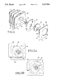
- FIG. 1 is a schematic view of a particle (wood chip) sizing apparatus incorporating the principles of the present invention.
- FIG. 2 is a schematic view showing an end portion of several bars in the bar screen of FIG. 1 and the means for supporting and moving the bars.
- FIGS. 3A-3D are side elevational views showing the relative movement at various points in time of the end portions of two adjacent bars in the bar screen of FIG. 1.
- FIG. 1 shows the particle bar screen of the present invention, arranged to separate a wood chip flow into those chips which are within an acceptable preestablished size range and those chips which are oversize in the thickness dimension, i.e. over-thick.
- the bar screen is shown generally at 10 and comprises a plurality, i.e. 25-30, of parallel rigid metal bars 12--12.
- the details of the geometry of the bar screen 10 and the bars 12, i.e. length, width, thickness, number, material and relative spacing will vary significantly from apparatus to apparatus. A preferred embodiment is disclosed in detail hereinafter.
- each bar 12 has a cam element 18 (FIG. 2) positioned in each end thereof.
- a camshaft 20 extends through an opening 21 in each cam element, thereby connecting the bars 12--12 together at their forward ends.
- a similar rear camshaft 20a connects the rear ends of the bars 12 in similar fashion.
- the opening 21 in the respective cam elements 18--18 is offset from the center of the cam element and is configured to receive the camshaft 20, which is square in cross section, so that rotation of the camshaft 20 will result in movement of the bars 12--12.
- the arrangement of the camshaft 20, the cam element 18 and the bars 12 is such that each point on the bar will move in a circle approximately one inch in diameter.
- the upper front corner of bar 12 will move vertically a total of one inch and horizontally a total of one inch during one complete revolution of camshaft 20.
- a drive motor 24 is connected to the camshaft 20.
- the rear camshaft 20a also includes a sprocket 28 on one end thereof, on the same side of the bar screen 10 as sprocket 26, so that sprockets 26 and 28 are in the same plane. Sprockets 26 and 28 are connected by a chain 30 so that when camshaft 20 is driven by drive motor 24, the rear camshaft 20a is driven as well.
- the bar screen 10 is supported on a base assembly shown generally at 32 which is open at its top, where the bar screen 10 is located.
- a conventional feed conveyer 34 moves particles to be sorted onto a downwardly inclined feed tray 36, which connects the feed conveyor 34 to the rear end 16 of the bar screen 10.
- an outlet tray 38 which guides the chips remaining on top of the bar screen 10 during operation thereof, when they reach the forward end 14 of the bar screen 10, to an over-thick conveyor 40.
- the conveyor 40 moves the over-thick chips to a slicer or other device (not shown) for reducing the size of the chips or to some other destination.
- bar screen 10 is supported so that it is flat in the embodiment shown.
- the bar screen 10 could be inclined downwardly, which would assist in the conveying, i.e. movement, of the chips from the rear end to the forward end of the bar screen 10, or the bar screen 10 could be inclined in the other direction, i.e. upwardly, in a particular application.
- the precise amount of the incline can be selected for a particular application.
- FIGS. 2 and 3 A portion of the plurality of bars 12--12 comprising the bar screen 10 is shown in FIG. 2.
- Each bar 12 includes a cam element 18 near the front end thereof.
- the cams 18 are circular and fit into a mating cutout portion 43 in a bar 12.
- the bars 12--12 are rectangular and relatively thin, approximately 1/4 inch thick. Generally, the thickness of the bars 12--12 is the minimum thickness which will result in an acceptable amount of deflection at the midspan point of the bars.
- the thickness dimension of the bars remains constant from the top edge 42 of the bar to the bottom 44 thereof. This appears to be the most effective cross-sectional shape, since it is easy to manufacture and inexpensive to replace. Other cross sectional shapes could be used, including elliptical, or round, or the bars could be inversely wedge-shaped with the large dimension at the top, or still further, the upper portion of the bar could be peaked so as to tip up the chips more effectively.
- the top surface 42 of each bar is smooth and flat. However, it could be roughened to some extent, or knurled or even have teeth of a selected size, to assist in the movement and agitation of the material being screened.
- the teeth could be relatively small, i.e. one-quarter inch, up to two inches high or more.
- the side surfaces 52 of each bar 12 may also have some contour or be abraded to some extent.
- the sides of adjacent bars are parallel, such that successive slots, defined by adjacent bars, have the same width from top to bottom.
- the slots may also have other shapes, including a configuration in which the space between bars increases from top to bottom, which could be accomplished by using tapered bars.
- camshaft 20 extends through each one of the cams 18 positioned in the bars 12.
- the camshaft 20 is square in cross-section, but could also have other shapes.
- the cam 18 is positioned midway between the top and bottom edges of each bar 12.
- the camshaft is offset from the center line of the bar so as to give the amount of bar movement desired.
- spacers 22 Positioned between the successive bars are spacers 22 which in the embodiment shown are circular, having a diameter slightly greater than the height of bars 12--12 and approximately the same thickness.
- the thickness of the spacer is independent of the thickness of the bar and is typically chosen to produce a slot width which will produce the desired particle separation.
- the slot width is slightly smaller than the desired particle size, i.e.
- the camshaft 20 extends through a matching hole 23 in each spacer 22.
- the cams and spacers comprise a low-friction, high wear plastic material, such as DELRIN, but could also alternatively comprise sealed roller bearings or other low friction materials or elements.
- the spacers shown have the advantage of being easy and inexpensive to disassemble in the field to replace worn bars and/or change spacer size so as to change the screen slot width and hence particle separation.
- the position of the cams 18 and in particular the openings 21 therein in the bars 12 determine the magnitude of movement of individual bars relative to the camshaft 20.
- the relative positioning of the cams 18 in successive bars determines the movement of the bars relative to each other.
- the bars from the two sets are arranged in alternating succession. As shown in FIG.
- the cams 18 in one set of bars are at their highest position, so that the bars of that set are all high, while the cams in the other set (alternating with first set) are all low so that the bars of the other set are all low.
- the screen 10 could comprise 3 or even more sets of alternating bars, although the sets should be balanced relative to each other (3 sets at 120°, 4 sets at 90° etc.), so as to minimize vibration and wear on bearing surfaces.
- FIGS. 3A-3D show the concept of relative movement of the two sets of bars of the present embodiment in a more detailed manner.
- a first bar 66 is shown with its cam 68, as well as a second adjacent bar 70 with its cam 72.
- a spacer 74 separates the two bars 66 and 70.
- Camshaft 76 extends through cams 68 and 72 and the spacer 74.
- Camshaft 76 is fixed in position, other than rotating counter-clockwise. Hence, movement of the two bars 66,70 is about the camshaft 76.
- FIG. 3A shows camshaft 76 at a first rotational position, in which the first bar 66 is in a relatively forward and relatively high position while bar 70 is in a relatively low and rear position.
- the two bars are exactly 180° out of phase, because the cams are positioned in the bars such that the respective openings therein are 180° apart.
- FIG. 3B shows the relative position of the two bars 66 and 70 following movement of the cam shaft 76 90° in a counter-clockwise direction.
- the first bar 66 is in a still relatively forward but now relatively low position in its path of movement while bar 70 is still relatively to the rear but also now relatively high.
- FIG. 3C shows the relative position of the two bars 66 and 70 when the camshaft 76 has moved another 90° counter-clockwise. In this position of the camshaft, the first bar 66 is now relatively to the rear and still relatively low, while the bar 70 has now moved to a forward position and is still relatively high.
- FIG. 3D shows the relative position of the bars 66 and 70 upon further rotation of the camshaft another 90°.
- the first bar 66 is still relatively to the rear but is now relatively high
- bar 70 is still relatively forward but now is relatively low as well.
- Another 90° rotation of the camshaft will bring the two bars 66,70 back to the position of FIG. 3A.
- bar 66 is representative of the movement of all the bars in one set
- bar 70 is representative of the movement of all the bars in the other set.
- other bar movement patterns could be used, including non-alternating sets, such as two consecutive bars up, two consecutive bars down, or other patterns
- the motion of the bars 12 is such that both ends of the bars 12 are always in the same relative vertical position, i.e. the respective ends of each bar always move in tandem, i.e. unison, as opposed to the relative position of the bar ends changing on a regular basis.
- Patterns of bar motion can be produced in which the incline or slope of the bar will vary on a cyclical basis.
- different types of bar drive devices could be utilized such that the ends of the bar will follow a different path than the circular path of the embodiment shown.
- the two sets of bars could be supported on two separate frames, with the frames then driven by separate cams.
- a single cam could also be used with a connecting arm to the frame.
- the inventor has discovered that the relative movement of the bars and the speed of the bars are both important to achieve effective screening action, keep the screen clear and prevent plugging. Movement of the bars alone is not sufficient to prevent plugging.
- the speed of the bars as well as the horizontal and vertical movement of the bars are such in combination that sufficient acceleration is imparted to the wood chips lying on top of the screen that the chips move about on the bar screen and encounter a slot between two adjacent bars.
- the acceleration will be approximately 1 G (32 feet per second per second) or slightly greater, such that the chips will just break contact with the bars at some point (overcome gravity) and will tend to become vertically oriented as they encounter a slot.
- a camshaft speed of 228 RPM is sufficient to achieve the desired results by imparting sufficient acceleration to the wood chips that the chips move about on the bar screen, the chips tending to be tipped up on edge and fall between adjacent bars, thereby encountering a slot in the screen. It is the combination of both vertical and horizontal motion of the bars and sufficient speed thereof which has been found to be effective.
- the bar screen of the present invention is inexpensive to manufacture and maintain, particularly compared to conventional disc screens, and furthermore is very efficient when compared to either a disc screen or gyratory screen alone, but also the combination of a gyratory screen and a disc screen. Over-thick removal efficiencies of approximately 96% have been obtained.
Abstract
Description
Claims (9)
Priority Applications (2)
| Application Number | Priority Date | Filing Date | Title |
|---|---|---|---|
| US07/390,620 US5117983A (en) | 1989-08-07 | 1989-08-07 | Bar screen having a reciprocating action |
| PCT/US1990/004423 WO1991001816A1 (en) | 1989-08-07 | 1990-08-07 | Bar screen having a reciprocating action |
Applications Claiming Priority (1)
| Application Number | Priority Date | Filing Date | Title |
|---|---|---|---|
| US07/390,620 US5117983A (en) | 1989-08-07 | 1989-08-07 | Bar screen having a reciprocating action |
Publications (1)
| Publication Number | Publication Date |
|---|---|
| US5117983A true US5117983A (en) | 1992-06-02 |
Family
ID=23543242
Family Applications (1)
| Application Number | Title | Priority Date | Filing Date |
|---|---|---|---|
| US07/390,620 Expired - Lifetime US5117983A (en) | 1989-08-07 | 1989-08-07 | Bar screen having a reciprocating action |
Country Status (2)
| Country | Link |
|---|---|
| US (1) | US5117983A (en) |
| WO (1) | WO1991001816A1 (en) |
Cited By (20)
| Publication number | Priority date | Publication date | Assignee | Title |
|---|---|---|---|---|
| US5284251A (en) * | 1992-07-21 | 1994-02-08 | Weyerhaeuser Co. | Tension bar screen |
| US5368168A (en) * | 1993-04-26 | 1994-11-29 | Weyerhaeuser Co. | Bar screen with bars of staggered height |
| US5392931A (en) * | 1993-09-30 | 1995-02-28 | Beloit Technologies, Inc. | Adjustable bar screen |
| US5398819A (en) * | 1994-01-13 | 1995-03-21 | Bmh Wood Technology, Inc. | Blade tensioning mechanism |
| WO1996014167A2 (en) * | 1994-10-31 | 1996-05-17 | Bmh Wood Technology, Inc. | An elastomeric joint for a blade tensioning mechanism |
| WO1996032203A1 (en) * | 1995-04-12 | 1996-10-17 | Weyerhaeuser Company | Wood chip screening apparatus with blades having nonlinear top edges |
| US5641073A (en) * | 1993-10-01 | 1997-06-24 | Radix Systems Limited | Aligning of elongated objects |
| US5782365A (en) * | 1995-10-03 | 1998-07-21 | Bmh Wood Technology, Inc. | Blade guide for a blade screen |
| WO2001076757A2 (en) * | 2000-04-05 | 2001-10-18 | Schmidt Karl W | Apparatus and method for separating corrugated paper |
| US6336560B1 (en) | 1996-07-31 | 2002-01-08 | Astec Industries, Inc. | Grizzly screening apparatus |
| US20060021915A1 (en) * | 2004-07-30 | 2006-02-02 | Suncor Energy Inc. | Sizing roller screen ore processing apparatus |
| US20080173572A1 (en) * | 2005-11-09 | 2008-07-24 | Suncor Energy Inc. | Method and apparatus for creating a slurry |
| US20100181394A1 (en) * | 2008-09-18 | 2010-07-22 | Suncor Energy, Inc. | Method and apparatus for processing an ore feed |
| US20110094944A1 (en) * | 2009-07-24 | 2011-04-28 | Suncor Energy Inc. | Screening disk, roller, and roller screen for screening an ore feed |
| KR101077994B1 (en) | 2004-12-28 | 2011-10-28 | 주식회사 포스코 | A rotating bar-screen for detaching cokes |
| US8708154B1 (en) | 2011-12-23 | 2014-04-29 | Tim Holmberg | Adjustable spring grizzly bar material separator |
| CN104578563A (en) * | 2015-01-29 | 2015-04-29 | 吴传涛 | Square shale shaker driving motor |
| DE202014005409U1 (en) * | 2014-06-17 | 2015-09-21 | Doppstadt Familienholding Gmbh | Separator, in particular ballistic separator |
| JP2020033801A (en) * | 2018-08-31 | 2020-03-05 | 株式会社タクマ | Sliding type bar screen and conveyance selection device using the same |
| US11548032B2 (en) * | 2018-01-31 | 2023-01-10 | Jx Nippon Mining & Metals Corporation | Method for removing wire-form objects, device for removing wire-form objects, and method for processing electronic/electrical apparatus component scrap |
Families Citing this family (2)
| Publication number | Priority date | Publication date | Assignee | Title |
|---|---|---|---|---|
| US5305891A (en) * | 1990-12-19 | 1994-04-26 | Beloit Technologies, Inc. | Wood chip bar screen deck arrangement |
| NZ240941A (en) * | 1990-12-19 | 1994-06-27 | Beloit Corp | Wood chip screening; two intermeshing horizontal grids oscillate material and allow accepts to pass therethrough |
Citations (17)
| Publication number | Priority date | Publication date | Assignee | Title |
|---|---|---|---|---|
| US210033A (en) * | 1878-11-19 | Improvement in corn-sheller separators | ||
| US975413A (en) * | 1909-09-20 | 1910-11-15 | Charles H Gunn | Shaking-grizzly. |
| US1136674A (en) * | 1914-02-06 | 1915-04-20 | Arthur Richard Houston | Screening-conveyer. |
| US2311169A (en) * | 1940-12-30 | 1943-02-16 | Washington State Hop Producers | Hop picking and cleaning machine |
| CA468403A (en) * | 1950-09-26 | B. Davies Stanley | Screening apparatus | |
| US3106523A (en) * | 1961-05-01 | 1963-10-08 | Lefebvre Freres Limitee | Grizzly bar feeder |
| US3254767A (en) * | 1961-04-12 | 1966-06-07 | Wehner Albert | Relatively movable bar screen with cleaners |
| US3805755A (en) * | 1972-09-25 | 1974-04-23 | Green Bay Res Corp | Engine vapor recycling device with improved action |
| US3971716A (en) * | 1974-11-27 | 1976-07-27 | Foreman Kenneth C | Rock separator |
| US4240588A (en) * | 1979-03-06 | 1980-12-23 | Fulghum Industries, Inc. | Wood chipping installation |
| SU1058639A1 (en) * | 1982-04-15 | 1983-12-07 | Калининский Ордена Трудового Красного Знамени Политехнический Институт | Apparatus for separation of loose material |
| US4430210A (en) * | 1979-07-13 | 1984-02-07 | Rauma-Repola Oy | Screen |
| US4504386A (en) * | 1983-05-16 | 1985-03-12 | Kmw Aktiebolag | Screening apparatus for wood chips |
| US4558787A (en) * | 1983-08-01 | 1985-12-17 | Marcus Danielsson | Screening device having a screen deck composed of two screen frames |
| US4660726A (en) * | 1983-06-15 | 1987-04-28 | Rudolf Woode | Bar screen |
| US4664790A (en) * | 1983-10-06 | 1987-05-12 | Svante Lundqvist | Method for screening of wooden chips and the like and a screen |
| SU1351698A1 (en) * | 1986-06-18 | 1987-11-15 | Всесоюзный научно-исследовательский горно-металлургический институт цветных металлов | Screen |
-
1989
- 1989-08-07 US US07/390,620 patent/US5117983A/en not_active Expired - Lifetime
-
1990
- 1990-08-07 WO PCT/US1990/004423 patent/WO1991001816A1/en unknown
Patent Citations (17)
| Publication number | Priority date | Publication date | Assignee | Title |
|---|---|---|---|---|
| US210033A (en) * | 1878-11-19 | Improvement in corn-sheller separators | ||
| CA468403A (en) * | 1950-09-26 | B. Davies Stanley | Screening apparatus | |
| US975413A (en) * | 1909-09-20 | 1910-11-15 | Charles H Gunn | Shaking-grizzly. |
| US1136674A (en) * | 1914-02-06 | 1915-04-20 | Arthur Richard Houston | Screening-conveyer. |
| US2311169A (en) * | 1940-12-30 | 1943-02-16 | Washington State Hop Producers | Hop picking and cleaning machine |
| US3254767A (en) * | 1961-04-12 | 1966-06-07 | Wehner Albert | Relatively movable bar screen with cleaners |
| US3106523A (en) * | 1961-05-01 | 1963-10-08 | Lefebvre Freres Limitee | Grizzly bar feeder |
| US3805755A (en) * | 1972-09-25 | 1974-04-23 | Green Bay Res Corp | Engine vapor recycling device with improved action |
| US3971716A (en) * | 1974-11-27 | 1976-07-27 | Foreman Kenneth C | Rock separator |
| US4240588A (en) * | 1979-03-06 | 1980-12-23 | Fulghum Industries, Inc. | Wood chipping installation |
| US4430210A (en) * | 1979-07-13 | 1984-02-07 | Rauma-Repola Oy | Screen |
| SU1058639A1 (en) * | 1982-04-15 | 1983-12-07 | Калининский Ордена Трудового Красного Знамени Политехнический Институт | Apparatus for separation of loose material |
| US4504386A (en) * | 1983-05-16 | 1985-03-12 | Kmw Aktiebolag | Screening apparatus for wood chips |
| US4660726A (en) * | 1983-06-15 | 1987-04-28 | Rudolf Woode | Bar screen |
| US4558787A (en) * | 1983-08-01 | 1985-12-17 | Marcus Danielsson | Screening device having a screen deck composed of two screen frames |
| US4664790A (en) * | 1983-10-06 | 1987-05-12 | Svante Lundqvist | Method for screening of wooden chips and the like and a screen |
| SU1351698A1 (en) * | 1986-06-18 | 1987-11-15 | Всесоюзный научно-исследовательский горно-металлургический институт цветных металлов | Screen |
Cited By (35)
| Publication number | Priority date | Publication date | Assignee | Title |
|---|---|---|---|---|
| US5284251A (en) * | 1992-07-21 | 1994-02-08 | Weyerhaeuser Co. | Tension bar screen |
| US5368168A (en) * | 1993-04-26 | 1994-11-29 | Weyerhaeuser Co. | Bar screen with bars of staggered height |
| US5560496A (en) * | 1993-09-30 | 1996-10-01 | Beloit Technologies, Inc. | Adjustable bar screen |
| US5392931A (en) * | 1993-09-30 | 1995-02-28 | Beloit Technologies, Inc. | Adjustable bar screen |
| US5392930A (en) * | 1993-09-30 | 1995-02-28 | Beloit Technologies, Inc. | Adjustable bar screen |
| US5641073A (en) * | 1993-10-01 | 1997-06-24 | Radix Systems Limited | Aligning of elongated objects |
| US5560729A (en) * | 1994-01-13 | 1996-10-01 | Bmh Wood Technology, Inc. | Elastomeric joint for a blade tensioning mechanism |
| WO1995019232A1 (en) * | 1994-01-13 | 1995-07-20 | Bmh Wood Technology, Inc. | Blade tensioning mechanism |
| US5398819A (en) * | 1994-01-13 | 1995-03-21 | Bmh Wood Technology, Inc. | Blade tensioning mechanism |
| WO1996014167A3 (en) * | 1994-10-31 | 1996-08-01 | Bmh Wood Tech Inc | An elastomeric joint for a blade tensioning mechanism |
| WO1996014167A2 (en) * | 1994-10-31 | 1996-05-17 | Bmh Wood Technology, Inc. | An elastomeric joint for a blade tensioning mechanism |
| WO1996032203A1 (en) * | 1995-04-12 | 1996-10-17 | Weyerhaeuser Company | Wood chip screening apparatus with blades having nonlinear top edges |
| US5782365A (en) * | 1995-10-03 | 1998-07-21 | Bmh Wood Technology, Inc. | Blade guide for a blade screen |
| US6336560B1 (en) | 1996-07-31 | 2002-01-08 | Astec Industries, Inc. | Grizzly screening apparatus |
| US6401937B1 (en) | 2000-04-05 | 2002-06-11 | Karl W. Schmidt | Apparatus and method to separate corrugated paper from commingled waste |
| WO2001076757A3 (en) * | 2000-04-05 | 2002-03-21 | Karl W Schmidt | Apparatus and method for separating corrugated paper |
| WO2001076757A2 (en) * | 2000-04-05 | 2001-10-18 | Schmidt Karl W | Apparatus and method for separating corrugated paper |
| US8851293B2 (en) | 2004-07-30 | 2014-10-07 | Suncor Energy, Inc. | Sizing roller screen ore processing apparatus |
| US7677397B2 (en) | 2004-07-30 | 2010-03-16 | Suncor Energy Inc. | Sizing roller screen ore processing apparatus |
| US20100155305A1 (en) * | 2004-07-30 | 2010-06-24 | Suncor Energy Inc. | Sizing roller screen ore processing apparatus |
| US20060021915A1 (en) * | 2004-07-30 | 2006-02-02 | Suncor Energy Inc. | Sizing roller screen ore processing apparatus |
| US8136672B2 (en) | 2004-07-30 | 2012-03-20 | Suncor Energy, Inc. | Sizing roller screen ore processing apparatus |
| KR101077994B1 (en) | 2004-12-28 | 2011-10-28 | 주식회사 포스코 | A rotating bar-screen for detaching cokes |
| US8393561B2 (en) | 2005-11-09 | 2013-03-12 | Suncor Energy Inc. | Method and apparatus for creating a slurry |
| US20080173572A1 (en) * | 2005-11-09 | 2008-07-24 | Suncor Energy Inc. | Method and apparatus for creating a slurry |
| US8328126B2 (en) | 2008-09-18 | 2012-12-11 | Suncor Energy, Inc. | Method and apparatus for processing an ore feed |
| US8622326B2 (en) | 2008-09-18 | 2014-01-07 | Suncor Energy, Inc. | Method and apparatus for processing an ore feed |
| US20100181394A1 (en) * | 2008-09-18 | 2010-07-22 | Suncor Energy, Inc. | Method and apparatus for processing an ore feed |
| US20110094944A1 (en) * | 2009-07-24 | 2011-04-28 | Suncor Energy Inc. | Screening disk, roller, and roller screen for screening an ore feed |
| US8646615B2 (en) | 2009-07-24 | 2014-02-11 | Suncor Energy Inc. | Screening disk, roller, and roller screen for screening an ore feed |
| US8708154B1 (en) | 2011-12-23 | 2014-04-29 | Tim Holmberg | Adjustable spring grizzly bar material separator |
| DE202014005409U1 (en) * | 2014-06-17 | 2015-09-21 | Doppstadt Familienholding Gmbh | Separator, in particular ballistic separator |
| CN104578563A (en) * | 2015-01-29 | 2015-04-29 | 吴传涛 | Square shale shaker driving motor |
| US11548032B2 (en) * | 2018-01-31 | 2023-01-10 | Jx Nippon Mining & Metals Corporation | Method for removing wire-form objects, device for removing wire-form objects, and method for processing electronic/electrical apparatus component scrap |
| JP2020033801A (en) * | 2018-08-31 | 2020-03-05 | 株式会社タクマ | Sliding type bar screen and conveyance selection device using the same |
Also Published As
| Publication number | Publication date |
|---|---|
| WO1991001816A1 (en) | 1991-02-21 |
Similar Documents
| Publication | Publication Date | Title |
|---|---|---|
| US5117983A (en) | Bar screen having a reciprocating action | |
| EP0340148B1 (en) | Apparatus for separating material by length | |
| US5799801A (en) | Method and apparatus for separating paper from cardboard | |
| EP0849006A2 (en) | Method and apparatus for sorting recycled material | |
| EP1358020B1 (en) | Apparatus and method to separate elements or materials of different sizes | |
| US5109988A (en) | Machine and method for sorting out fines, pins, and over-thick wood chips | |
| US4504386A (en) | Screening apparatus for wood chips | |
| US4058201A (en) | Method and apparatus for orienting wood strands into parallelism | |
| RU2094133C1 (en) | Wood chip screen deck | |
| KR950000229A (en) | Selector | |
| CA1155377A (en) | Apparatus for aligning chips during the manufacture of chipboards | |
| US4802591A (en) | Louvered chip screener | |
| EP0552250A1 (en) | Magnetic separator assembly for use in material separator equipment. | |
| JPH0759795B2 (en) | Wood particle screen | |
| US5279427A (en) | Rotary feed table for food product and sliver remover | |
| WO1992005881A1 (en) | Bar screen having a reciprocating action | |
| JP2527522B2 (en) | Loras screen for separating bulk materials, especially wood chips | |
| GB2268919A (en) | Arrangement for sorting out thin and/or short rib pieces of tobacco. | |
| US4391374A (en) | Method of and apparatus for separating elongated articles by length | |
| US5368168A (en) | Bar screen with bars of staggered height | |
| US3921809A (en) | Fruit cleaner | |
| CA2036571C (en) | Machine and method for separating out fines, pins and over-thick wood chips | |
| AU605451B2 (en) | Louvered chip screener | |
| EP0820354A1 (en) | Wood chip screening apparatus with blades having nonlinear top edges | |
| PT95208B (en) | BARRIER OF BARS WITH ACTION OF ALTERNATIVE MOVEMENT |
Legal Events
| Date | Code | Title | Description |
|---|---|---|---|
| AS | Assignment |
Owner name: WEYERHAEUSER COMPANY TACOMA, WA 98477 Free format text: ASSIGNMENT OF ASSIGNORS INTEREST.;ASSIGNOR:MARRS, GEVAN R.;REEL/FRAME:005111/0355 Effective date: 19890721 |
|
| STCF | Information on status: patent grant |
Free format text: PATENTED CASE |
|
| CC | Certificate of correction | ||
| FEPP | Fee payment procedure |
Free format text: PAYOR NUMBER ASSIGNED (ORIGINAL EVENT CODE: ASPN); ENTITY STATUS OF PATENT OWNER: LARGE ENTITY |
|
| FPAY | Fee payment |
Year of fee payment: 4 |
|
| FPAY | Fee payment |
Year of fee payment: 8 |
|
| FPAY | Fee payment |
Year of fee payment: 12 |
|
| AS | Assignment |
Owner name: WEYERHAEUSER NR COMPANY, WASHINGTON Free format text: ASSIGNMENT OF ASSIGNORS INTEREST;ASSIGNOR:WEYERHAEUSER COMPANY;REEL/FRAME:022835/0233 Effective date: 20090421 Owner name: WEYERHAEUSER NR COMPANY,WASHINGTON Free format text: ASSIGNMENT OF ASSIGNORS INTEREST;ASSIGNOR:WEYERHAEUSER COMPANY;REEL/FRAME:022835/0233 Effective date: 20090421 |