US5119283A - High power factor, voltage-doubler rectifier - Google Patents
High power factor, voltage-doubler rectifier Download PDFInfo
- Publication number
- US5119283A US5119283A US07/712,371 US71237191A US5119283A US 5119283 A US5119283 A US 5119283A US 71237191 A US71237191 A US 71237191A US 5119283 A US5119283 A US 5119283A
- Authority
- US
- United States
- Prior art keywords
- voltage
- output
- coupled
- rectifier
- boost
- Prior art date
- Legal status (The legal status is an assumption and is not a legal conclusion. Google has not performed a legal analysis and makes no representation as to the accuracy of the status listed.)
- Expired - Fee Related
Links
Images


Classifications
-
- H—ELECTRICITY
- H02—GENERATION; CONVERSION OR DISTRIBUTION OF ELECTRIC POWER
- H02M—APPARATUS FOR CONVERSION BETWEEN AC AND AC, BETWEEN AC AND DC, OR BETWEEN DC AND DC, AND FOR USE WITH MAINS OR SIMILAR POWER SUPPLY SYSTEMS; CONVERSION OF DC OR AC INPUT POWER INTO SURGE OUTPUT POWER; CONTROL OR REGULATION THEREOF
- H02M1/00—Details of apparatus for conversion
- H02M1/42—Circuits or arrangements for compensating for or adjusting power factor in converters or inverters
- H02M1/4208—Arrangements for improving power factor of AC input
-
- H—ELECTRICITY
- H02—GENERATION; CONVERSION OR DISTRIBUTION OF ELECTRIC POWER
- H02M—APPARATUS FOR CONVERSION BETWEEN AC AND AC, BETWEEN AC AND DC, OR BETWEEN DC AND DC, AND FOR USE WITH MAINS OR SIMILAR POWER SUPPLY SYSTEMS; CONVERSION OF DC OR AC INPUT POWER INTO SURGE OUTPUT POWER; CONTROL OR REGULATION THEREOF
- H02M1/00—Details of apparatus for conversion
- H02M1/10—Arrangements incorporating converting means for enabling loads to be operated at will from different kinds of power supplies, e.g. from ac or dc
-
- H—ELECTRICITY
- H02—GENERATION; CONVERSION OR DISTRIBUTION OF ELECTRIC POWER
- H02M—APPARATUS FOR CONVERSION BETWEEN AC AND AC, BETWEEN AC AND DC, OR BETWEEN DC AND DC, AND FOR USE WITH MAINS OR SIMILAR POWER SUPPLY SYSTEMS; CONVERSION OF DC OR AC INPUT POWER INTO SURGE OUTPUT POWER; CONTROL OR REGULATION THEREOF
- H02M1/00—Details of apparatus for conversion
- H02M1/42—Circuits or arrangements for compensating for or adjusting power factor in converters or inverters
- H02M1/4208—Arrangements for improving power factor of AC input
- H02M1/4275—Arrangements for improving power factor of AC input by adding an auxiliary output voltage in series to the input
-
- Y—GENERAL TAGGING OF NEW TECHNOLOGICAL DEVELOPMENTS; GENERAL TAGGING OF CROSS-SECTIONAL TECHNOLOGIES SPANNING OVER SEVERAL SECTIONS OF THE IPC; TECHNICAL SUBJECTS COVERED BY FORMER USPC CROSS-REFERENCE ART COLLECTIONS [XRACs] AND DIGESTS
- Y02—TECHNOLOGIES OR APPLICATIONS FOR MITIGATION OR ADAPTATION AGAINST CLIMATE CHANGE
- Y02B—CLIMATE CHANGE MITIGATION TECHNOLOGIES RELATED TO BUILDINGS, e.g. HOUSING, HOUSE APPLIANCES OR RELATED END-USER APPLICATIONS
- Y02B70/00—Technologies for an efficient end-user side electric power management and consumption
- Y02B70/10—Technologies improving the efficiency by using switched-mode power supplies [SMPS], i.e. efficient power electronics conversion e.g. power factor correction or reduction of losses in power supplies or efficient standby modes
-
- Y—GENERAL TAGGING OF NEW TECHNOLOGICAL DEVELOPMENTS; GENERAL TAGGING OF CROSS-SECTIONAL TECHNOLOGIES SPANNING OVER SEVERAL SECTIONS OF THE IPC; TECHNICAL SUBJECTS COVERED BY FORMER USPC CROSS-REFERENCE ART COLLECTIONS [XRACs] AND DIGESTS
- Y02—TECHNOLOGIES OR APPLICATIONS FOR MITIGATION OR ADAPTATION AGAINST CLIMATE CHANGE
- Y02P—CLIMATE CHANGE MITIGATION TECHNOLOGIES IN THE PRODUCTION OR PROCESSING OF GOODS
- Y02P80/00—Climate change mitigation technologies for sector-wide applications
- Y02P80/10—Efficient use of energy, e.g. using compressed air or pressurized fluid as energy carrier
Definitions
- the present invention relates generally to ac-to-dc power converters and, more particularly, to a voltage-doubler rectifier, applicable to both U.S. and European ac power sources, which operates with high power factor and low harmonic distortion.
- a high power factor dc output power supply having only one power stage is described in commonly assigned, copending U.S. patent application of R.L. Steigerwald, Ser. No. 652,831, filed Feb. 8, 1991, which is incorporated by reference herein.
- the power supply of the Steigerwald patent application includes a dual-output switching converter having a first output coupled in series between a rectifier circuit and the input to the switching converter for providing a high power factor, and a second output for providing a regulated dc voltage at the power supply output.
- the first and second outputs are decoupled, resulting in a power supply capable of drawing high quality current waveforms from an ac source while producing a regulated dc output voltage with fast transient response.
- high power factor is obtained without requiring a separate up-front power converter so that the power delivered by the supply does not have to be converted twice.
- an object of the present invention is to provide a new and improved voltage-doubler rectifier operating with high power factor.
- Another object of the present invention is to provide a high power factor, voltage-doubler rectifier which operates at high power factor without having to convert the entire power twice.
- Yet another object of the present invention is to provide a high power factor, voltage-doubler rectifier applicable to both U.S. and European ac power sources.
- a new and improved voltage-doubler rectifier including a full-wave diode rectifier and a dc-to-dc converter having two output boost circuits.
- One of the output boost circuits is coupled between the diode rectifier and a positive dc link, and the other output boost circuit is coupled between the diode rectifier and the circuit common, i.e., negative dc link.
- Two series-connected filter capacitors are also coupled between the positive dc link and the circuit common.
- the two output boost circuits each comprise either a series, parallel, or combination series/parallel resonant circuit and a rectifier.
- a switch means is coupled between the junction joining one pair of diodes of the full-bridge rectifier and the junction joining the two filter capacitors.
- the switch means For a relatively high ac line voltage, the switch means is open, and the circuit operates in a low boost mode.
- the switch means is closed, and the circuit operates in a high boost, or voltage-doubling, mode.
- the switch means operates automatically.
- the voltage-doubler rectifier of the present invention enables efficient converter operation at high power factor over a wide ac input voltage range by providing a voltage doubler dc output voltage (i.e., a positive dc link voltage) in a substantially constant range. Such a voltage-doubler rectifier is thus applicable to, for example, both U.S. and European ac power sources.
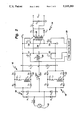
- FIG. 1 is a schematic illustration of a voltage-doubler rectifier according to the present invention
- FIG. 2 is a schematic illustration of a power supply employing a voltage-doubler rectifier according to a preferred embodiment invention.
- FIGS. 3A-3C schematic illustrations of alternative embodiments of the output boost circuits useful in the voltage-doubler rectifier of FIG. 2.
- FIG. 1 illustrates a voltage-doubler rectifier (also referred to herein as a voltage doubler) according to the present invention.
- the voltage doubler includes a full-wave rectifier 10, having diodes D 1 -D 4 connected together in a full-bridge configuration, coupled through an input filter inductor L in to ac power source 12.
- a dual-output, dc-to-dc converter 14 is coupled between a positive dc link voltage Ed and the circuit common.
- Two filter capacitors C 1 and C 2 are also coupled between the dc link voltage Ed and the circuit common.
- the dc-to-dc converter has two output boost circuits 16 and 18 inductively coupled thereto via a boost transformer T b having a primary winding 20 and two secondary windings 21 and 22.
- One of the output boost circuits 16 is connected in series between rectifier 10 and the dc link voltage E d ; and the other output boost circuit 18 is connected, with opposite polarity, in series between the rectifier and the circuit common.
- Boost circuit 16 generates an output boost voltage V ab between terminals a and b; and boost circuit 18 generates an output boost voltage V a'b' between terminals a' and b'.
- a switch S is coupled between the junctions joining diodes D 3 and D 4 of full-bridge rectifier 10 and filter capacitors C 1 and C 2 , respectively. The switch S preferably operates automatically according to methods well-known in the art.
- the dc-to-dc converter 14 provides a regulated dc output voltage E out .
- the switch S In operation, for relatively high ac line voltages (e.g. 240V in Europe), the switch S is open, and operation is in a low boost mode. That is, the rectifier diodes D 1- D 4 act as a conventional full-wave rectifier, and the series boost voltages V ab and V a'b' are added in series with the rectifier 10 and the dc link filter capacitors C 1 and C 2 .
- the switch S is closed, and operation is in a high boost, or voltage-doubling, mode.
- each capacitor C 1 and C 2 is charged to a voltage higher than the peak of the ac line voltage so that the series combination of the voltages across capacitors C 1 and C 2 results in the same dc link voltage E d as when the switch S was open, i.e., during the low boost mode.
- the respective boost voltages, V ab and V a'b' are controlled as described hereinbelow such that near sinusoidal currents are drawn from the ac line. The result is high power factor voltage doubling.
- FIG. 2 illustrates a high power factor voltage-doubler rectifier in accordance with a preferred embodiment of the present invention.
- dual-output, dc-to-dc converter 14 has a phase-shifted, PWM-controlled output and a resonant output.
- Converter 14 includes a full-bridge connection of switching devices Q 1 -Q 4 l between the dc link voltage Ed and the circuit common.
- Pulse width modulation and frequency modulation (PWM and FM) means 30 is shown as being coupled to the gates of switching devices Q 1 -Q 4 .
- the output boost circuits 16 and 18 of resonant converter 14 are each illustrated in FIG. 2 as including a resonant capacitor C r and a resonant inductor L r coupled in series with each other and with a boost transformer secondary winding 21 and 22, respectively.
- the output boost circuits 16 and 18 of FIG. 2 each further include a full-wave bridge rectifier comprising diodes D 5-D 8 .
- boost circuit 16 the anodes of diodes D.sub.
- boost circuit 18 the anodes of diodes D 5 and D 6 are connected to the dc link at terminal b', and the cathodes of diodes D 6 and D 8 are connected to the full-bridge rectifier 10 at terminal a'.
- the series resonant circuit is coupled between the junctions joining diodes D 5 -D 6 and D 7 -D 8 , respectively.
- the resonant circuits are illustrated as being situated on the secondary side of the boost transformer T b , the resonant circuits may alternatively be situated on the primary side, as will be appreciated by those of ordinary skill in the art.
- output boost circuits 16 and 18 are illustrated as including series resonant circuits, it is to be understood that the advantages of the present invention may also be realized using other resonant circuit configurations.
- a parallel resonant circuit configuration may be employed wherein the resonant capacitor C r is situated in parallel with the series combination of resonant inductor L r and the boost transformer secondary winding, rather than in series therewith as shown in FIG. 2.
- FIG. 3A a parallel resonant circuit configuration may be employed wherein the resonant capacitor C r is situated in parallel with the series combination of resonant inductor L r and the boost transformer secondary winding, rather than in series therewith as shown in FIG. 2.
- FIG. 3A a parallel resonant circuit configuration may be employed wherein the resonant capacitor C r is situated in parallel with the series combination of resonant inductor L r and the boost transformer secondary winding, rather than in series therewith as shown in FIG. 2.
- FIG. 3A a parallel
- a combination series/parallel resonant circuit may be employed wherein another capacitor C rr is coupled in parallel with the series combination of resonant inductor L r , resonant capacitor C r and the secondary winding of boost transformer T b .
- the resonant circuit components may be situated on either the primary or secondary side of boost transformer T b , as desired.
- FIG. 3C illustrates another alternative embodiment of the output boost circuits 16 and 18 wherein a center-tapped boost transformer secondary winding is coupled to a center-tapped full-wave boost rectifier comprising diodes D 9 and D 10 .
- a combination series/parallel resonant circuit is shown with capacitor C r and inductor L r being situated between terminals c and d on the primary side of the boost transformer, and capacitor C rr being situated on the secondary side of the boost transformer.
- the primary winding 24 of an output transformer T o is coupled across the junctions joining the switching devices Q 1 -Q 2 and Q 3 -Q 4 of the respective fullbridge converter legs.
- the respective terminals of the secondary winding 25 of transformer T o are connected to the anodes of diodes D 11 and D 12 .
- the cathodes of diodes D 11 and D 12 are connected to an output filter inductor L o and an output filter capacitor C o .
- the regulated dc output voltage E out is provided across capacitor C o .
- Boost voltages V ab and V a'b are controlled by the switching frequency of full-bridge converter switching devices Q 1 -Q 4 via a first ac signal generated across the resonant circuits and load by boost transformer T b , while the dc output voltage E out is controlled by pulse width modulation (PWM) of a second ac signal generated across transformer T o , i.e., by phase-shifting the two legs of the converter bridge with respect to each other. Because phase-shifting the fullbridge converter legs does not affect the voltage applied to the boost transformer T b , the boost voltages V ab and V a'b' are independent of the output voltage E out . As a result, a fast transient response can be attained for the boost output circuits 16 and 18 and the output voltage E out simultaneously.
- PWM pulse width modulation
- a suitable control for the power converter of the present invention is described in Steigerwald and Kornrumpf U.S. Pat. No. 4,642,745, issued Feb. 10, 1987, which patent is incorporated by reference herein.
- the Steigerwald and Kornrumpf patent describes a PWM control for controlling the regulated dc output voltage E out by adjusting the duty cycle of the inverter output signal whenever an error is detected between a commanded dc output voltage E out and the actual dc output voltage E out .
- the Steigerwald and Kornrumpf patent describes an active frequency control wherein the actual converter input current is compared with a commanded current in phase with the utility line voltage; any difference causes a frequency adjustment for controlling each output boost circuit.
- any adjustment of the dc output voltage using the Steigerwald and Kornrumpf control system will have negligible effect on the input current to the voltage-doubler rectifier of the present invention.
- the voltage-doubler rectifier of the present invention operates with a relatively high power factor and low peak ac line current, due to the favorable gain characteristics of the resonant circuits.
- the frequency control portion of the Steigerwald and Kornrumpf control, U.S. Pat. No. 4,642,745 could be eliminated as described in the Steigerwald application, Ser. No. 652,831, thereby simplifying the controls for the voltage doubler provided that somewhat higher harmonic line currents can be tolerated.
- the peak power rating of the output boost circuits is less than the total power delivered to the dc link E d , and high power factor voltage-doubling is achieved without requiring a separate up-front converter. That is, a separate up-front converter is not required to convert the entire power as in conventional high power factor schemes.
Abstract
A voltage-doubler rectifier includes an ac fullbridge diode rectifier and a dc-to-dc converter having two output boost circuits. One of the output boost circuits is coupled between the rectifier and a dc link, and the other output boost circuit is coupled, with opposite polarity, between the rectifier and the circuit common. Two series-connected filter capacitors are also coupled between the dc link and the circuit common. In a preferred embodiment, the two output boost circuits each comprise either a series, parallel, or combination series/parallel resonant circuit and a rectifier. A switch is coupled between the junction joining one pair of diodes of the rectifier and the junction joining the two filter capacitors. For a relatively high ac line voltage, the switch is open, and the circuit operates in a low boost mode. For a relatively low ac line voltage, the switch is closed, and the circuit operates in a high boost, or voltage-doubling, mode.
Description
The present invention relates generally to ac-to-dc power converters and, more particularly, to a voltage-doubler rectifier, applicable to both U.S. and European ac power sources, which operates with high power factor and low harmonic distortion.
Conventional rectifier circuits with capacitive output filters have relatively low power factors which limit the power that can be drawn from an ac line to a fraction of the rating of the line. Furthermore, highly distorted ac line currents are drawn by these conventional rectifiers, often causing interference with other electrical equipment in addition to equipment overcurrents and overvoltages. Techniques for improving power factor include passive waveform shaping methods, i.e. using input filters, and active methods, i.e. using boost or buck converter topologies. Such conventional active methods of obtaining high power factor generally employ a completely separate upfront converter to attain the high power factor followed by a dc-to-dc converter to produce the desired regulated dc output voltage. Thus, the power is converted twice, which is costly and inefficient. Moreover, the up-front converter must convert the entire delivered power. In fact, it must convert a peak power equal to twice the average power delivered.
A high power factor dc output power supply having only one power stage is described in commonly assigned, copending U.S. patent application of R.L. Steigerwald, Ser. No. 652,831, filed Feb. 8, 1991, which is incorporated by reference herein. The power supply of the Steigerwald patent application includes a dual-output switching converter having a first output coupled in series between a rectifier circuit and the input to the switching converter for providing a high power factor, and a second output for providing a regulated dc voltage at the power supply output. The first and second outputs are decoupled, resulting in a power supply capable of drawing high quality current waveforms from an ac source while producing a regulated dc output voltage with fast transient response. Furthermore, with the aforementioned Steigerwald power supply, high power factor is obtained without requiring a separate up-front power converter so that the power delivered by the supply does not have to be converted twice.
In addition to the hereinabove enumerated advantages of the high power factor power supply of the Steigerwald patent application, Ser. No. 652,831, cited hereinabove, it is also desirable to provide a high power factor, voltage-doubler rectifier for power conversion over a very wide input voltage range, e.g., applicable to both U.S. and European ac power sources. Conventional voltage-doubler rectifiers have poor power factor and relatively high harmonic distortion. Unfortunately, a practical solution is not to merely increase the boost voltage of the aforementioned Steigerwald power supply in order to offset a low input line voltage, because substantial circulating power, i.e., power greater than that delivered to the dc link, would result.
Accordingly, an object of the present invention is to provide a new and improved voltage-doubler rectifier operating with high power factor.
Another object of the present invention is to provide a high power factor, voltage-doubler rectifier which operates at high power factor without having to convert the entire power twice.
Yet another object of the present invention is to provide a high power factor, voltage-doubler rectifier applicable to both U.S. and European ac power sources.
These and other objects of the present invention are achieved in a new and improved voltage-doubler rectifier including a full-wave diode rectifier and a dc-to-dc converter having two output boost circuits. One of the output boost circuits is coupled between the diode rectifier and a positive dc link, and the other output boost circuit is coupled between the diode rectifier and the circuit common, i.e., negative dc link. Two series-connected filter capacitors are also coupled between the positive dc link and the circuit common. In one preferred embodiment, the two output boost circuits each comprise either a series, parallel, or combination series/parallel resonant circuit and a rectifier. A switch means is coupled between the junction joining one pair of diodes of the full-bridge rectifier and the junction joining the two filter capacitors. For a relatively high ac line voltage, the switch means is open, and the circuit operates in a low boost mode. On the other hand, for a relatively low ac line voltage, the switch means is closed, and the circuit operates in a high boost, or voltage-doubling, mode. Preferably, the switch means operates automatically. Advantageously, the voltage-doubler rectifier of the present invention enables efficient converter operation at high power factor over a wide ac input voltage range by providing a voltage doubler dc output voltage (i.e., a positive dc link voltage) in a substantially constant range. Such a voltage-doubler rectifier is thus applicable to, for example, both U.S. and European ac power sources.
The features and advantages of the present invention will become apparent from the following detailed description of the invention when read with the accompanying drawings in which:
FIG. 1 is a schematic illustration of a voltage-doubler rectifier according to the present invention;
FIG. 2 is a schematic illustration of a power supply employing a voltage-doubler rectifier according to a preferred embodiment invention; and
FIGS. 3A-3C schematic illustrations of alternative embodiments of the output boost circuits useful in the voltage-doubler rectifier of FIG. 2.
FIG. 1 illustrates a voltage-doubler rectifier (also referred to herein as a voltage doubler) according to the present invention. As shown, the voltage doubler includes a full-wave rectifier 10, having diodes D1 -D4 connected together in a full-bridge configuration, coupled through an input filter inductor Lin to ac power source 12. A dual-output, dc-to-dc converter 14 is coupled between a positive dc link voltage Ed and the circuit common. Two filter capacitors C1 and C2 are also coupled between the dc link voltage Ed and the circuit common. The dc-to-dc converter has two output boost circuits 16 and 18 inductively coupled thereto via a boost transformer Tb having a primary winding 20 and two secondary windings 21 and 22. One of the output boost circuits 16 is connected in series between rectifier 10 and the dc link voltage Ed ; and the other output boost circuit 18 is connected, with opposite polarity, in series between the rectifier and the circuit common. Boost circuit 16 generates an output boost voltage Vab between terminals a and b; and boost circuit 18 generates an output boost voltage Va'b' between terminals a' and b'. A switch S is coupled between the junctions joining diodes D3 and D4 of full-bridge rectifier 10 and filter capacitors C1 and C2, respectively. The switch S preferably operates automatically according to methods well-known in the art. The dc-to-dc converter 14 provides a regulated dc output voltage Eout.
In operation, for relatively high ac line voltages (e.g. 240V in Europe), the switch S is open, and operation is in a low boost mode. That is, the rectifier diodes D1- D4 act as a conventional full-wave rectifier, and the series boost voltages Vab and Va'b' are added in series with the rectifier 10 and the dc link filter capacitors C1 and C2. On the other hand, for relatively low ac line voltages (e.g. 120V in the U.S.), the switch S is closed, and operation is in a high boost, or voltage-doubling, mode. In the voltage-doubling mode, during one half cycle of the ac line voltage, current flows through diode D1 and boost circuit 16 to charge capacitor C1 through switch S. Similarly, during the next half cycle, current flows through diode D2 and boost circuit 18 to charge capacitor C2 through switch S. During the voltage-doubling mode, each capacitor C1 and C2 is charged to a voltage higher than the peak of the ac line voltage so that the series combination of the voltages across capacitors C1 and C2 results in the same dc link voltage Ed as when the switch S was open, i.e., during the low boost mode. Furthermore, during each half cycle, the respective boost voltages, Vab and Va'b', are controlled as described hereinbelow such that near sinusoidal currents are drawn from the ac line. The result is high power factor voltage doubling.
FIG. 2 illustrates a high power factor voltage-doubler rectifier in accordance with a preferred embodiment of the present invention. As shown, dual-output, dc-to-dc converter 14 has a phase-shifted, PWM-controlled output and a resonant output. (However, it is to be understood that the principles of the present invention apply to other types of dual-output converters, e.g., load-resonant, quasi-resonant, hard-switched PWM converters and the like.) Converter 14 includes a full-bridge connection of switching devices Q1 -Q4 l between the dc link voltage Ed and the circuit common. Pulse width modulation and frequency modulation (PWM and FM) means 30 is shown as being coupled to the gates of switching devices Q1 -Q4. The output boost circuits 16 and 18 of resonant converter 14 are each illustrated in FIG. 2 as including a resonant capacitor Cr and a resonant inductor Lr coupled in series with each other and with a boost transformer secondary winding 21 and 22, respectively. The output boost circuits 16 and 18 of FIG. 2 each further include a full-wave bridge rectifier comprising diodes D5-D 8. In boost circuit 16, the anodes of diodes D.sub. 5 and D7 are connected to the dc link at terminal b, and the cathodes of diodes D6 and D8 of boost circuit 16 are connected to the dc link at terminal a. Conversely, in boost circuit 18, the anodes of diodes D5 and D6 are connected to the dc link at terminal b', and the cathodes of diodes D6 and D8 are connected to the full-bridge rectifier 10 at terminal a'. In each boost circuit, the series resonant circuit is coupled between the junctions joining diodes D5 -D6 and D7 -D8, respectively. However, although the resonant circuits are illustrated as being situated on the secondary side of the boost transformer Tb, the resonant circuits may alternatively be situated on the primary side, as will be appreciated by those of ordinary skill in the art.
Although the output boost circuits 16 and 18 are illustrated as including series resonant circuits, it is to be understood that the advantages of the present invention may also be realized using other resonant circuit configurations. For example, as shown in FIG. 3A, a parallel resonant circuit configuration may be employed wherein the resonant capacitor Cr is situated in parallel with the series combination of resonant inductor Lr and the boost transformer secondary winding, rather than in series therewith as shown in FIG. 2. As another example, as shown in FIG. 3B, a combination series/parallel resonant circuit may be employed wherein another capacitor Crr is coupled in parallel with the series combination of resonant inductor Lr, resonant capacitor Cr and the secondary winding of boost transformer Tb. Again, it is to be noted that the resonant circuit components may be situated on either the primary or secondary side of boost transformer Tb, as desired.
FIG. 3C illustrates another alternative embodiment of the output boost circuits 16 and 18 wherein a center-tapped boost transformer secondary winding is coupled to a center-tapped full-wave boost rectifier comprising diodes D9 and D10. For purposes of illustration, a combination series/parallel resonant circuit is shown with capacitor Cr and inductor Lr being situated between terminals c and d on the primary side of the boost transformer, and capacitor Crr being situated on the secondary side of the boost transformer.
As shown in FIG. 2, the primary winding 24 of an output transformer To is coupled across the junctions joining the switching devices Q1 -Q2 and Q3 -Q4 of the respective fullbridge converter legs. The respective terminals of the secondary winding 25 of transformer To are connected to the anodes of diodes D11 and D12. The cathodes of diodes D11 and D12 are connected to an output filter inductor Lo and an output filter capacitor Co. The regulated dc output voltage Eout is provided across capacitor Co.
Boost voltages Vab and Va'b are controlled by the switching frequency of full-bridge converter switching devices Q1 -Q4 via a first ac signal generated across the resonant circuits and load by boost transformer Tb, while the dc output voltage Eout is controlled by pulse width modulation (PWM) of a second ac signal generated across transformer To, i.e., by phase-shifting the two legs of the converter bridge with respect to each other. Because phase-shifting the fullbridge converter legs does not affect the voltage applied to the boost transformer Tb, the boost voltages Vab and Va'b' are independent of the output voltage Eout. As a result, a fast transient response can be attained for the boost output circuits 16 and 18 and the output voltage Eout simultaneously.
A suitable control for the power converter of the present invention is described in Steigerwald and Kornrumpf U.S. Pat. No. 4,642,745, issued Feb. 10, 1987, which patent is incorporated by reference herein. The Steigerwald and Kornrumpf patent describes a PWM control for controlling the regulated dc output voltage Eout by adjusting the duty cycle of the inverter output signal whenever an error is detected between a commanded dc output voltage Eout and the actual dc output voltage Eout. In addition, the Steigerwald and Kornrumpf patent describes an active frequency control wherein the actual converter input current is compared with a commanded current in phase with the utility line voltage; any difference causes a frequency adjustment for controlling each output boost circuit. Advantageously, since the output boost circuits 16 and 18 and the output voltage Eout of the present invention are completely decoupled, any adjustment of the dc output voltage using the Steigerwald and Kornrumpf control system will have negligible effect on the input current to the voltage-doubler rectifier of the present invention.
Advantageously, similar to the high power factor power supply of the Steigerwald patent application, Ser. No. 652,831, even with no active control of the ac line current, the voltage-doubler rectifier of the present invention operates with a relatively high power factor and low peak ac line current, due to the favorable gain characteristics of the resonant circuits. Hence, the frequency control portion of the Steigerwald and Kornrumpf control, U.S. Pat. No. 4,642,745, could be eliminated as described in the Steigerwald application, Ser. No. 652,831, thereby simplifying the controls for the voltage doubler provided that somewhat higher harmonic line currents can be tolerated.
As another advantage, as a result of the series connection of the output boost circuits between the rectifier and the dc-to-dc converter, the peak power rating of the output boost circuits is less than the total power delivered to the dc link Ed, and high power factor voltage-doubling is achieved without requiring a separate up-front converter. That is, a separate up-front converter is not required to convert the entire power as in conventional high power factor schemes.
While the preferred embodiments of the present invention have been shown and described herein, it will be obvious that such embodiments are provided by way of example only. Numerous variations, changes and substitutions will occur to those of skill in the art without departing from the invention herein. Accordingly, it is intended that the invention be limited only by the spirit and scope of the appended claims.
Claims (7)
1. A high power factor voltage-doubler rectifier for providing a dc output voltage, comprising:
a rectifier including two pairs of series-connected diodes in a full-bridge configuration for providing a rectified ac voltage when coupled to an ac power line, said rectifier having a cathode and an anode;
dc-to-dc converter means coupled between said dc output voltage and a common potential, said dc-to-dc converter means having first and second output boost circuits inductively coupled thereto, said first output boost circuit being coupled in series between the cathode of said rectifier and said dc output voltage, and said second output boost circuit being coupled in series, with a polarity opposite to that of said first output boost circuit, between the anode of said rectifier and said common potential;
a pair of filter capacitors connected in series with a junction therebetween, the series combination of said filter capacitors being coupled between said dc output voltage and said common potential; and
switch means coupled between the junction joining the diodes of one of said two pairs and the junction joining said filter capacitors, said switch means being closed to enable operation in a voltage-doubling mode for relatively low input ac line voltages, and said switch means being open to enable operation in a low boost mode for relatively high input ac line voltages, said output dc voltage being maintained in substantially the same range in both said modes of operation.
2. The voltage-doubler rectifier of claim 1 wherein said first and second output boost circuits each comprise a resonant circuit including a resonant capacitor and a resonant inductor, said first and second output boost circuits each including a boost transformer for coupling to said dc-to-dc converter means.
3. The voltage-doubler rectifier of claim 2 wherein each said resonant circuit comprises a series resonant circuit, said resonant capacitor being coupled in series with said resonant inductor.
4. The voltage-doubler rectifier of claim 2 wherein each said resonant circuit comprises a parallel resonant circuit, said resonant capacitor being coupled in parallel with a series combination of said resonant inductor and said boost transformer.
5. The voltage-doubler rectifier of claim 2 wherein each said resonant circuit comprises a combination series/parallel resonant circuit including an additional resonant capacitor coupled in parallel with a series combination of said resonant capacitor, said resonant inductor and said boost transformer.
6. The voltage-doubler rectifier of claim 1 wherein said dc-to-dc converter means further comprises:
an inverter coupled between said dc output voltage and said common potential for providing a first ac signal for exciting said output boost circuits, said inverter further providing a second ac signal;
an output rectifier for receiving said second ac signal and generating a second regulated dc output voltage therefrom; and
pulse width modulation means coupled to said inverter for controlling the amplitude of said second regulated dc output voltage by pulse width modulating said second ac signal.
7. The voltage-doubler rectifier of claim 6, further comprising frequency modulation means for controlling the frequency of said first ac signal in a manner to cause said dc-to-dc converter means to draw substantially sinusoidal current from said ac power line in phase with the voltage of said power line.
Priority Applications (4)
| Application Number | Priority Date | Filing Date | Title |
|---|---|---|---|
| US07/712,371 US5119283A (en) | 1991-06-10 | 1991-06-10 | High power factor, voltage-doubler rectifier |
| PCT/US1992/005047 WO1992022952A1 (en) | 1991-06-10 | 1992-06-10 | High power factor, voltage-doubler rectifier |
| JP5501076A JP2635820B2 (en) | 1991-06-10 | 1992-06-10 | High power factor double voltage rectifier |
| EP92915024A EP0543005A1 (en) | 1991-06-10 | 1992-06-10 | High power factor, voltage-doubler rectifier |
Applications Claiming Priority (1)
| Application Number | Priority Date | Filing Date | Title |
|---|---|---|---|
| US07/712,371 US5119283A (en) | 1991-06-10 | 1991-06-10 | High power factor, voltage-doubler rectifier |
Publications (1)
| Publication Number | Publication Date |
|---|---|
| US5119283A true US5119283A (en) | 1992-06-02 |
Family
ID=24861829
Family Applications (1)
| Application Number | Title | Priority Date | Filing Date |
|---|---|---|---|
| US07/712,371 Expired - Fee Related US5119283A (en) | 1991-06-10 | 1991-06-10 | High power factor, voltage-doubler rectifier |
Country Status (4)
| Country | Link |
|---|---|
| US (1) | US5119283A (en) |
| EP (1) | EP0543005A1 (en) |
| JP (1) | JP2635820B2 (en) |
| WO (1) | WO1992022952A1 (en) |
Cited By (90)
| Publication number | Priority date | Publication date | Assignee | Title |
|---|---|---|---|---|
| US5253157A (en) * | 1992-02-06 | 1993-10-12 | Premier Power, Inc. | Half-bridge inverter with capacitive voltage equalizer |
| US5283726A (en) * | 1991-12-20 | 1994-02-01 | Wilkerson A W | AC line current controller utilizing line connected inductance and DC voltage component |
| GB2273212A (en) * | 1992-12-01 | 1994-06-08 | Univ Cardiff | Converter for switched reluctance motor |
| US5383109A (en) * | 1993-12-10 | 1995-01-17 | University Of Colorado | High power factor boost rectifier apparatus |
| US5438500A (en) * | 1991-06-19 | 1995-08-01 | Ant Nachrichtentechnik Gmbh | Switching regulator with a push-pull resonance converter |
| EP0671810A1 (en) * | 1994-03-09 | 1995-09-13 | Whirlpool Europe B.V. | High frequency control circuit for DC motors, particularly for washing machines |
| DE4414194A1 (en) * | 1994-04-22 | 1995-10-26 | Niepenberg Dalex Werke | Electronic circuit with rectifier circuit for supplying DC voltage to appliances from AC mains supply |
| US5481449A (en) * | 1994-03-21 | 1996-01-02 | General Electric Company | Efficient, high power density, high power factor converter for very low dc voltage applications |
| US5499187A (en) * | 1995-04-03 | 1996-03-12 | Arinc Research Corporation | Voltage sensing, autoselecting aircraft power supply interface |
| US5502630A (en) * | 1994-07-19 | 1996-03-26 | Transistor Devices, Inc. | Power factor corrected rectification |
| US5502628A (en) * | 1991-12-27 | 1996-03-26 | Toko, Inc. | AC-DC converter |
| EP0720276A1 (en) * | 1994-12-29 | 1996-07-03 | I-Hits Laboratory | Single phase input hybrid rectification method |
| EP0725475A1 (en) * | 1995-02-02 | 1996-08-07 | Sanken Electric Co., Ltd. | DC converter with improved power factor |
| US5563781A (en) * | 1993-11-24 | 1996-10-08 | Integrated Technology Corporation | Dual-mode power converter |
| US5568041A (en) * | 1995-02-09 | 1996-10-22 | Magnetek, Inc. | Low-cost power factor correction circuit and method for electronic ballasts |
| US5572415A (en) * | 1993-07-09 | 1996-11-05 | Sgs-Thomson Microelectronics Pte. Limited | DC voltage supply circuit for rectifying an AC input voltage to provide a substantially constant DC output voltage |
| US5577153A (en) * | 1994-01-25 | 1996-11-19 | Whirlpool Europe B.V. | High frequency control circuit for DC motors, particularly for washing machines |
| US5610805A (en) * | 1995-01-10 | 1997-03-11 | Cambridge Continuous Power | Uninterruptible power supply with a back-up battery coupled across the a.c. input |
| US5661348A (en) * | 1995-07-18 | 1997-08-26 | Dell Usa L.P. | Method and apparatus for passive input current waveform correction for universal offline switchmode power supply |
| EP0838893A2 (en) * | 1996-10-28 | 1998-04-29 | Sony Corporation | Power source apparatus |
| US5781427A (en) * | 1995-10-30 | 1998-07-14 | Sgs-Thomson Microelectronics S.A. | Multistandard rectified power supply circuit with power factor correction option |
| US5793626A (en) * | 1996-05-29 | 1998-08-11 | Lucent Technologies Inc. | High efficiency bimodal power converter and method of operation thereof |
| US5831846A (en) * | 1997-08-22 | 1998-11-03 | Lucent Technologies Inc. | Dual mode boost converter and method of operation thereof |
| CN1043394C (en) * | 1995-07-24 | 1999-05-12 | 大宇电子株式会社 | Power converting circuit |
| US5915070A (en) * | 1996-12-30 | 1999-06-22 | Zexel Corporation | Motor driving apparatus for pulse-width modulation controlling a DC voltage according to a rotation speed setting information |
| US5933338A (en) * | 1997-10-14 | 1999-08-03 | Peco Ii, Inc. | Dual coupled current doubler rectification circuit |
| US5978236A (en) * | 1997-01-31 | 1999-11-02 | Silverline Power Conversion Llc | Uninterruptible power supply with direction of DC electrical energy depending on predetermined ratio |
| US5999418A (en) * | 1997-11-13 | 1999-12-07 | Schneider Electric Sa | Control device for an electromagnet coil |
| US6002603A (en) * | 1999-02-25 | 1999-12-14 | Elliott Energy Systems, Inc. | Balanced boost/buck DC to DC converter |
| US6023416A (en) * | 1997-10-20 | 2000-02-08 | Sansha Electric Manufacturing Company, Limited | DC power supply apparatus including boosting/lowering converter unit and control |
| US6154380A (en) * | 1996-08-22 | 2000-11-28 | Telefonaktiebolaget Lm Ericsson | AC/DC boost converter |
| US6166924A (en) * | 1995-11-03 | 2000-12-26 | Telefonaktiebolaget Lm Ericsson | Device and method of supplying energy from an ac source in an ac to dc converter |
| US6178101B1 (en) | 1997-08-15 | 2001-01-23 | Unitron, Inc. | Power supply regulation |
| EP1076403A2 (en) * | 1999-08-13 | 2001-02-14 | Powerware Corporation | Multi-mode power converters incorporating balancer circuits and methods of operation thereof |
| US6198257B1 (en) * | 1999-10-01 | 2001-03-06 | Metropolitan Industries, Inc. | Transformerless DC-to-AC power converter and method |
| US6225862B1 (en) * | 1998-11-13 | 2001-05-01 | Lamda Electronics Inc. | Series resonant circuit with inherent short circuit protection |
| WO2001065659A2 (en) * | 2000-02-29 | 2001-09-07 | Powerware Corporation | Power converters with ac and dc operating modes and methods of operation thereof |
| US6356467B1 (en) | 1999-10-01 | 2002-03-12 | Metropolitan Industries, Inc. | DC/DC boost converter with bypass circuitry |
| US6404655B1 (en) | 1999-12-07 | 2002-06-11 | Semikron, Inc. | Transformerless 3 phase power inverter |
| US6407936B1 (en) * | 2001-03-13 | 2002-06-18 | Astec International Limited | Capacitive boost for line harmonic improvement in power converters |
| US6449180B1 (en) * | 1999-11-02 | 2002-09-10 | Samsung Electronics Co., Ltd. | World wide power supply apparatus that includes a relay switch voltage doubling circuit |
| US6459603B1 (en) * | 2001-04-02 | 2002-10-01 | International Business Machines Corporation | Adapter circuit for selectively doubling input voltage depending upon connector type |
| US6466459B2 (en) * | 2001-03-01 | 2002-10-15 | Adtec International Ltd. | Passive voltage clamp for rectifier diodes in a soft-switching DC/DC converter |
| US6483730B2 (en) | 1999-08-13 | 2002-11-19 | Powerware Corporation | Power converters with AC and DC operating modes and methods of operation thereof |
| US6549441B1 (en) * | 1998-11-12 | 2003-04-15 | Fronius Schweissmaschinen Produktion Gmbh & Co, Kg | Voltage switch-over device |
| US6608770B2 (en) * | 2001-08-31 | 2003-08-19 | Vlt Corporation | Passive control of harmonic current drawn from an AC input by rectification circuitry |
| US6819576B2 (en) | 1999-08-13 | 2004-11-16 | Powerware Corporation | Power conversion apparatus and methods using balancer circuits |
| US20040257835A1 (en) * | 2003-06-20 | 2004-12-23 | Comarco Wireless Technologies, Inc. | Programmable AC/DC power supply |
| US6980451B2 (en) * | 2001-11-27 | 2005-12-27 | Power Integrations, Inc. | Method and apparatus for balancing active capacitor leakage current |
| US20060187693A1 (en) * | 2005-02-23 | 2006-08-24 | Allen Pak Chuen Tang | Power factor correction apparatus |
| US20070057284A1 (en) * | 2005-08-02 | 2007-03-15 | Leo Francis Casey | Double-sided package for power module |
| US20070115704A1 (en) * | 2004-11-02 | 2007-05-24 | Nec Electronics Corporation | Apparatus and method for power conversion having diode in charging and discharging circuit |
| CN100403637C (en) * | 2006-12-12 | 2008-07-16 | 浙江大学 | Passive clamping soft switch high gain boost interleaved parallel converter |
| FR2927201A1 (en) * | 2008-01-31 | 2009-08-07 | Airbus France Sas | Power rectifier circuit for aircraft, has boost cells arranged in cascade such that output terminals of cell are respectively connected to input terminals of following boost cell, and terminal capacitors and cells have common terminals |
| US20090303762A1 (en) * | 2008-06-05 | 2009-12-10 | Delta Electronics, Inc. | Power factor correction rectifier that operates efficiently over a range of input voltage conditions |
| US20090310394A1 (en) * | 2007-12-27 | 2009-12-17 | Toshiba Carrier Corporation | Direct-current power supply apparatus |
| CN101388610B (en) * | 2008-07-08 | 2010-06-02 | 河北省电力研究院 | Voltage mutual inductor resonance step-up method in related full closed combined electrical equipment |
| US8023290B2 (en) | 1997-01-24 | 2011-09-20 | Synqor, Inc. | High efficiency power converter |
| KR101106505B1 (en) | 2010-10-01 | 2012-01-20 | 성호전자(주) | Soft-switching two-inductor boost converter |
| US8159198B2 (en) | 2008-10-28 | 2012-04-17 | International Business Machines Corporation | Power supply that adjusts a transformer turns ratio to operate efficiently at high and low line input |
| KR101249385B1 (en) * | 2011-12-13 | 2013-04-01 | 전자부품연구원 | Bidirectional dc/dc converter system of transformer series construction and driving method thereof |
| KR101283964B1 (en) | 2011-12-13 | 2013-07-15 | 전자부품연구원 | Bidirectional DC/DC Converter System Using Interleave Method And Driving Method thereof |
| US20130327842A1 (en) * | 2011-01-28 | 2013-12-12 | Websato SE | Electric heating, vehicle comprising an electric heating as well as method for controlling an electric heating |
| CN103888004A (en) * | 2014-04-08 | 2014-06-25 | 青岛威控电气有限公司 | Single-phase PWM rectifier for railway AC/DC/AC standby power supply |
| TWI504126B (en) * | 2013-05-17 | 2015-10-11 | Hep Tech Co Ltd | Full - bridge AC / DC conversion device and its conversion method |
| US20150357912A1 (en) * | 2013-04-09 | 2015-12-10 | Massachusetts Institute Of Technology | Method and apparatus to provide power conversion with high power factor |
| US20160006365A1 (en) * | 2014-07-03 | 2016-01-07 | Massachusetts Institute Of Technology | High-Frequency, High Density Power Factor Correction Conversion For Universal Input Grid Interface |
| KR101613537B1 (en) | 2011-12-31 | 2016-04-19 | 눅테크 컴퍼니 리미티드 | Power source for outputting high voltage pulse mudulation and method therof |
| US9502992B2 (en) | 2012-06-01 | 2016-11-22 | Coriant Operations, Inc. | Diode substitute with low drop and minimal loading |
| US9667139B2 (en) | 2008-05-08 | 2017-05-30 | Massachusetts Institute Of Technology | Power converter with capacitive energy transfer and fast dynamic response |
| US9825545B2 (en) | 2013-10-29 | 2017-11-21 | Massachusetts Institute Of Technology | Switched-capacitor split drive transformer power conversion circuit |
| US20180234028A1 (en) * | 2017-02-14 | 2018-08-16 | Yang Chen | Hybrid Full Bridge-Voltage Doubler Rectifier and Single Stage LLC Converter Thereof |
| DE102017106424A1 (en) * | 2017-03-24 | 2018-09-27 | Infineon Technologies Austria Ag | Power converter circuit comprising a main converter and an auxiliary converter |
| US10199950B1 (en) | 2013-07-02 | 2019-02-05 | Vlt, Inc. | Power distribution architecture with series-connected bus converter |
| US10498225B2 (en) * | 2018-04-24 | 2019-12-03 | Shanghai Tuituo Technology Co., Ltd | Dual-rectification full bridge interleaved single stage PFC converter circuit and control methods thereof |
| US10498226B2 (en) * | 2018-04-24 | 2019-12-03 | Shanghai Tuituo Technology Co., Ltd | Dual-rectification bridge type single stage PFC converter |
| US10574130B2 (en) * | 2018-05-23 | 2020-02-25 | Nidec Asi S.P.A. | Electric power converter |
| US10855086B2 (en) | 2004-01-15 | 2020-12-01 | Comarco Wireless Systems Llc | Power supply equipment utilizing interchangeable tips to provide power and a data signal to electronic devices |
| CN112260558A (en) * | 2019-04-03 | 2021-01-22 | 矽力杰半导体技术(杭州)有限公司 | AC-DC conversion circuit and method and charger |
| US10917007B2 (en) | 2011-05-05 | 2021-02-09 | Psemi Corporation | Power converter with modular stages connected by floating terminals |
| CN112689364A (en) * | 2021-01-21 | 2021-04-20 | 矽力杰半导体技术(杭州)有限公司 | Power converter |
| CN112689363A (en) * | 2021-01-21 | 2021-04-20 | 矽力杰半导体技术(杭州)有限公司 | Power converter |
| US11075586B2 (en) * | 2017-09-04 | 2021-07-27 | Omron Corporation | Solar power system and converter |
| US11211861B2 (en) | 2011-05-05 | 2021-12-28 | Psemi Corporation | DC-DC converter with modular stages |
| CN113972827A (en) * | 2020-07-22 | 2022-01-25 | 广东美的制冷设备有限公司 | Totem-pole PFC circuit and control method thereof, circuit board, air conditioner and storage medium |
| US11303205B2 (en) | 2011-05-05 | 2022-04-12 | Psemi Corporation | Power converters with modular stages |
| US11316424B2 (en) | 2011-05-05 | 2022-04-26 | Psemi Corporation | Dies with switches for operating a switched-capacitor power converter |
| US11482944B2 (en) * | 2018-02-15 | 2022-10-25 | Huawei Digital Power Technologies Co., Ltd. | AC to DC converter with parallel converter |
| US11901817B2 (en) | 2013-03-15 | 2024-02-13 | Psemi Corporation | Protection of switched capacitor power converter |
| CN113972827B (en) * | 2020-07-22 | 2024-04-26 | 广东美的制冷设备有限公司 | Totem pole PFC circuit, control method thereof, circuit board, air conditioner and storage medium |
Families Citing this family (1)
| Publication number | Priority date | Publication date | Assignee | Title |
|---|---|---|---|---|
| JP4842998B2 (en) * | 2008-06-18 | 2011-12-21 | 日立アプライアンス株式会社 | Electromagnetic induction heating device |
Citations (6)
| Publication number | Priority date | Publication date | Assignee | Title |
|---|---|---|---|---|
| US3851182A (en) * | 1973-09-04 | 1974-11-26 | North Electric Co | Bias transformer for dual voltage input off-line converters |
| US4642745A (en) * | 1986-03-03 | 1987-02-10 | General Electric Company | Power circuit with high input power factor and a regulated output |
| US4780805A (en) * | 1987-07-21 | 1988-10-25 | Ncr Corporation | Low/high input voltage power supply |
| US4930061A (en) * | 1989-04-07 | 1990-05-29 | At&T Bell Laboratories | Method and network for enhancing power factor of off-line switching circuit |
| US4959766A (en) * | 1989-07-07 | 1990-09-25 | National Research Council Of Canada/Conseil National De Recherches Du Canada | AC/DC converter using resonant network for high input power factor |
| US4967333A (en) * | 1988-06-17 | 1990-10-30 | General Electric Cgr S.A. | Stabilized power supply with reduced ripple factor |
Family Cites Families (2)
| Publication number | Priority date | Publication date | Assignee | Title |
|---|---|---|---|---|
| GB8333627D0 (en) * | 1983-12-16 | 1984-01-25 | Nada Electronics Ltd | Switched mode power supply |
| US4864488A (en) * | 1988-06-27 | 1989-09-05 | Ncr Corporation | Single level D.C. output voltage power supply |
-
1991
- 1991-06-10 US US07/712,371 patent/US5119283A/en not_active Expired - Fee Related
-
1992
- 1992-06-10 WO PCT/US1992/005047 patent/WO1992022952A1/en not_active Application Discontinuation
- 1992-06-10 JP JP5501076A patent/JP2635820B2/en not_active Expired - Lifetime
- 1992-06-10 EP EP92915024A patent/EP0543005A1/en not_active Withdrawn
Patent Citations (6)
| Publication number | Priority date | Publication date | Assignee | Title |
|---|---|---|---|---|
| US3851182A (en) * | 1973-09-04 | 1974-11-26 | North Electric Co | Bias transformer for dual voltage input off-line converters |
| US4642745A (en) * | 1986-03-03 | 1987-02-10 | General Electric Company | Power circuit with high input power factor and a regulated output |
| US4780805A (en) * | 1987-07-21 | 1988-10-25 | Ncr Corporation | Low/high input voltage power supply |
| US4967333A (en) * | 1988-06-17 | 1990-10-30 | General Electric Cgr S.A. | Stabilized power supply with reduced ripple factor |
| US4930061A (en) * | 1989-04-07 | 1990-05-29 | At&T Bell Laboratories | Method and network for enhancing power factor of off-line switching circuit |
| US4959766A (en) * | 1989-07-07 | 1990-09-25 | National Research Council Of Canada/Conseil National De Recherches Du Canada | AC/DC converter using resonant network for high input power factor |
Cited By (134)
| Publication number | Priority date | Publication date | Assignee | Title |
|---|---|---|---|---|
| US5438500A (en) * | 1991-06-19 | 1995-08-01 | Ant Nachrichtentechnik Gmbh | Switching regulator with a push-pull resonance converter |
| US5283726A (en) * | 1991-12-20 | 1994-02-01 | Wilkerson A W | AC line current controller utilizing line connected inductance and DC voltage component |
| US5502628A (en) * | 1991-12-27 | 1996-03-26 | Toko, Inc. | AC-DC converter |
| US5253157A (en) * | 1992-02-06 | 1993-10-12 | Premier Power, Inc. | Half-bridge inverter with capacitive voltage equalizer |
| GB2273212A (en) * | 1992-12-01 | 1994-06-08 | Univ Cardiff | Converter for switched reluctance motor |
| US5572415A (en) * | 1993-07-09 | 1996-11-05 | Sgs-Thomson Microelectronics Pte. Limited | DC voltage supply circuit for rectifying an AC input voltage to provide a substantially constant DC output voltage |
| US5563781A (en) * | 1993-11-24 | 1996-10-08 | Integrated Technology Corporation | Dual-mode power converter |
| US5383109A (en) * | 1993-12-10 | 1995-01-17 | University Of Colorado | High power factor boost rectifier apparatus |
| US5577153A (en) * | 1994-01-25 | 1996-11-19 | Whirlpool Europe B.V. | High frequency control circuit for DC motors, particularly for washing machines |
| EP0671810A1 (en) * | 1994-03-09 | 1995-09-13 | Whirlpool Europe B.V. | High frequency control circuit for DC motors, particularly for washing machines |
| US5481449A (en) * | 1994-03-21 | 1996-01-02 | General Electric Company | Efficient, high power density, high power factor converter for very low dc voltage applications |
| DE4414194A1 (en) * | 1994-04-22 | 1995-10-26 | Niepenberg Dalex Werke | Electronic circuit with rectifier circuit for supplying DC voltage to appliances from AC mains supply |
| US5502630A (en) * | 1994-07-19 | 1996-03-26 | Transistor Devices, Inc. | Power factor corrected rectification |
| EP0720276A1 (en) * | 1994-12-29 | 1996-07-03 | I-Hits Laboratory | Single phase input hybrid rectification method |
| US5610805A (en) * | 1995-01-10 | 1997-03-11 | Cambridge Continuous Power | Uninterruptible power supply with a back-up battery coupled across the a.c. input |
| EP0725475A1 (en) * | 1995-02-02 | 1996-08-07 | Sanken Electric Co., Ltd. | DC converter with improved power factor |
| US5568041A (en) * | 1995-02-09 | 1996-10-22 | Magnetek, Inc. | Low-cost power factor correction circuit and method for electronic ballasts |
| US5499187A (en) * | 1995-04-03 | 1996-03-12 | Arinc Research Corporation | Voltage sensing, autoselecting aircraft power supply interface |
| US5661348A (en) * | 1995-07-18 | 1997-08-26 | Dell Usa L.P. | Method and apparatus for passive input current waveform correction for universal offline switchmode power supply |
| CN1043394C (en) * | 1995-07-24 | 1999-05-12 | 大宇电子株式会社 | Power converting circuit |
| US5781427A (en) * | 1995-10-30 | 1998-07-14 | Sgs-Thomson Microelectronics S.A. | Multistandard rectified power supply circuit with power factor correction option |
| US6046922A (en) * | 1995-10-30 | 2000-04-04 | Sgs-Thomson Microelectronics S.A. | Multistandard rectified power supply circuit |
| US6166924A (en) * | 1995-11-03 | 2000-12-26 | Telefonaktiebolaget Lm Ericsson | Device and method of supplying energy from an ac source in an ac to dc converter |
| US5793626A (en) * | 1996-05-29 | 1998-08-11 | Lucent Technologies Inc. | High efficiency bimodal power converter and method of operation thereof |
| US6154380A (en) * | 1996-08-22 | 2000-11-28 | Telefonaktiebolaget Lm Ericsson | AC/DC boost converter |
| EP0838893A2 (en) * | 1996-10-28 | 1998-04-29 | Sony Corporation | Power source apparatus |
| CN1068995C (en) * | 1996-10-28 | 2001-07-25 | 索尼公司 | Power source apparatus |
| EP0838893A3 (en) * | 1996-10-28 | 1999-06-02 | Sony Corporation | Power source apparatus |
| US5915070A (en) * | 1996-12-30 | 1999-06-22 | Zexel Corporation | Motor driving apparatus for pulse-width modulation controlling a DC voltage according to a rotation speed setting information |
| US8023290B2 (en) | 1997-01-24 | 2011-09-20 | Synqor, Inc. | High efficiency power converter |
| US9143042B2 (en) | 1997-01-24 | 2015-09-22 | Synqor, Inc. | High efficiency power converter |
| US8493751B2 (en) | 1997-01-24 | 2013-07-23 | Synqor, Inc. | High efficiency power converter |
| US5978236A (en) * | 1997-01-31 | 1999-11-02 | Silverline Power Conversion Llc | Uninterruptible power supply with direction of DC electrical energy depending on predetermined ratio |
| US6178101B1 (en) | 1997-08-15 | 2001-01-23 | Unitron, Inc. | Power supply regulation |
| US5831846A (en) * | 1997-08-22 | 1998-11-03 | Lucent Technologies Inc. | Dual mode boost converter and method of operation thereof |
| US5933338A (en) * | 1997-10-14 | 1999-08-03 | Peco Ii, Inc. | Dual coupled current doubler rectification circuit |
| US6023416A (en) * | 1997-10-20 | 2000-02-08 | Sansha Electric Manufacturing Company, Limited | DC power supply apparatus including boosting/lowering converter unit and control |
| US5999418A (en) * | 1997-11-13 | 1999-12-07 | Schneider Electric Sa | Control device for an electromagnet coil |
| US6549441B1 (en) * | 1998-11-12 | 2003-04-15 | Fronius Schweissmaschinen Produktion Gmbh & Co, Kg | Voltage switch-over device |
| US6225862B1 (en) * | 1998-11-13 | 2001-05-01 | Lamda Electronics Inc. | Series resonant circuit with inherent short circuit protection |
| US6002603A (en) * | 1999-02-25 | 1999-12-14 | Elliott Energy Systems, Inc. | Balanced boost/buck DC to DC converter |
| US6483730B2 (en) | 1999-08-13 | 2002-11-19 | Powerware Corporation | Power converters with AC and DC operating modes and methods of operation thereof |
| EP1076403A3 (en) * | 1999-08-13 | 2002-01-02 | Powerware Corporation | Multi-mode power converters incorporating balancer circuits and methods of operation thereof |
| EP1076403A2 (en) * | 1999-08-13 | 2001-02-14 | Powerware Corporation | Multi-mode power converters incorporating balancer circuits and methods of operation thereof |
| US6819576B2 (en) | 1999-08-13 | 2004-11-16 | Powerware Corporation | Power conversion apparatus and methods using balancer circuits |
| US6356467B1 (en) | 1999-10-01 | 2002-03-12 | Metropolitan Industries, Inc. | DC/DC boost converter with bypass circuitry |
| US6198257B1 (en) * | 1999-10-01 | 2001-03-06 | Metropolitan Industries, Inc. | Transformerless DC-to-AC power converter and method |
| US6449180B1 (en) * | 1999-11-02 | 2002-09-10 | Samsung Electronics Co., Ltd. | World wide power supply apparatus that includes a relay switch voltage doubling circuit |
| US6404655B1 (en) | 1999-12-07 | 2002-06-11 | Semikron, Inc. | Transformerless 3 phase power inverter |
| WO2001065659A2 (en) * | 2000-02-29 | 2001-09-07 | Powerware Corporation | Power converters with ac and dc operating modes and methods of operation thereof |
| WO2001065659A3 (en) * | 2000-02-29 | 2002-03-14 | Powerware Corp | Power converters with ac and dc operating modes and methods of operation thereof |
| US6466459B2 (en) * | 2001-03-01 | 2002-10-15 | Adtec International Ltd. | Passive voltage clamp for rectifier diodes in a soft-switching DC/DC converter |
| US6407936B1 (en) * | 2001-03-13 | 2002-06-18 | Astec International Limited | Capacitive boost for line harmonic improvement in power converters |
| US6459603B1 (en) * | 2001-04-02 | 2002-10-01 | International Business Machines Corporation | Adapter circuit for selectively doubling input voltage depending upon connector type |
| US6608770B2 (en) * | 2001-08-31 | 2003-08-19 | Vlt Corporation | Passive control of harmonic current drawn from an AC input by rectification circuitry |
| US7397680B2 (en) | 2001-11-27 | 2008-07-08 | Power Integrations, Inc. | Method and apparatus for balancing active capacitor leakage current |
| US6980451B2 (en) * | 2001-11-27 | 2005-12-27 | Power Integrations, Inc. | Method and apparatus for balancing active capacitor leakage current |
| US20060067096A1 (en) * | 2001-11-27 | 2006-03-30 | Odell Arthur B | Method and apparatus for balancing active capacitor leakage current |
| US7133301B2 (en) | 2001-11-27 | 2006-11-07 | Power Integrations, Inc. | Method and apparatus for balancing active capacitor leakage current |
| US20070035977A1 (en) * | 2001-11-27 | 2007-02-15 | Odell Arthur B | Method and apparatus for balancing active capacitor leakage current |
| US7148659B2 (en) * | 2003-06-20 | 2006-12-12 | Comarco Wireless Technologies, Inc. | Programmable AC/DC power supply |
| EP1521353A3 (en) * | 2003-06-20 | 2006-08-02 | Comarco Wireless Technologies, Inc. | Programmable AC/DC power supply |
| US7254048B2 (en) | 2003-06-20 | 2007-08-07 | Comarco Wireless Technologies, Inc. | Power supply capable of AC and DC input utilizing winding of transformer as boost inductor |
| US20040257835A1 (en) * | 2003-06-20 | 2004-12-23 | Comarco Wireless Technologies, Inc. | Programmable AC/DC power supply |
| US11586233B2 (en) | 2004-01-15 | 2023-02-21 | Comarco Wireless Systems Llc | Power supply systems |
| US10951042B2 (en) | 2004-01-15 | 2021-03-16 | Comarco Wireless Systems Llc | Power supply systems |
| US10855087B1 (en) | 2004-01-15 | 2020-12-01 | Comarco Wireless Systems Llc | Power supply systems |
| US10855086B2 (en) | 2004-01-15 | 2020-12-01 | Comarco Wireless Systems Llc | Power supply equipment utilizing interchangeable tips to provide power and a data signal to electronic devices |
| US20070115704A1 (en) * | 2004-11-02 | 2007-05-24 | Nec Electronics Corporation | Apparatus and method for power conversion having diode in charging and discharging circuit |
| US7443705B2 (en) * | 2004-11-02 | 2008-10-28 | Nec Electronics Corporation | Apparatus and method for power conversion having diode in charging and discharging circuit |
| US20060187693A1 (en) * | 2005-02-23 | 2006-08-24 | Allen Pak Chuen Tang | Power factor correction apparatus |
| US20070057284A1 (en) * | 2005-08-02 | 2007-03-15 | Leo Francis Casey | Double-sided package for power module |
| US7786486B2 (en) | 2005-08-02 | 2010-08-31 | Satcon Technology Corporation | Double-sided package for power module |
| CN100403637C (en) * | 2006-12-12 | 2008-07-16 | 浙江大学 | Passive clamping soft switch high gain boost interleaved parallel converter |
| US7848127B2 (en) * | 2007-12-27 | 2010-12-07 | Toshiba Carrier Corporation | Direct-current power supply apparatus with improved power factor |
| US20090310394A1 (en) * | 2007-12-27 | 2009-12-17 | Toshiba Carrier Corporation | Direct-current power supply apparatus |
| FR2927201A1 (en) * | 2008-01-31 | 2009-08-07 | Airbus France Sas | Power rectifier circuit for aircraft, has boost cells arranged in cascade such that output terminals of cell are respectively connected to input terminals of following boost cell, and terminal capacitors and cells have common terminals |
| WO2009109714A3 (en) * | 2008-01-31 | 2009-11-26 | Airbus Operations | Power rectifying circuit and systems, associated method, and aircraft including such circuit or systems |
| US20110002148A1 (en) * | 2008-01-31 | 2011-01-06 | Airbus Operations (Sas) | Power rectifier circuit and systems, associated method, and aircraft comprising such a circuit or systems |
| WO2009109714A2 (en) * | 2008-01-31 | 2009-09-11 | Airbus France | Power rectifying circuit and systems, associated method, and aircraft including such circuit or systems |
| US8467206B2 (en) | 2008-01-31 | 2013-06-18 | Airbus Operations S.A.S. | Power rectifier circuit and systems, associated method, and aircraft comprising such a circuit or systems |
| US11245330B2 (en) | 2008-05-08 | 2022-02-08 | Massachusetts Institute Of Technology | Power converter with capacitive energy transfer and fast dynamic response |
| US10541611B2 (en) | 2008-05-08 | 2020-01-21 | Massachusetts Institute Of Technology | Power converter with capacitive energy transfer and fast dynamic response |
| US11736010B2 (en) | 2008-05-08 | 2023-08-22 | Massachusetts Institute Of Technology | Power converter with capacitive energy transfer and fast dynamic response |
| US9667139B2 (en) | 2008-05-08 | 2017-05-30 | Massachusetts Institute Of Technology | Power converter with capacitive energy transfer and fast dynamic response |
| US8233298B2 (en) * | 2008-06-05 | 2012-07-31 | Delta Electronics, Inc. | Power factor correction rectifier that operates efficiently over a range of input voltage conditions |
| US20090303762A1 (en) * | 2008-06-05 | 2009-12-10 | Delta Electronics, Inc. | Power factor correction rectifier that operates efficiently over a range of input voltage conditions |
| CN101388610B (en) * | 2008-07-08 | 2010-06-02 | 河北省电力研究院 | Voltage mutual inductor resonance step-up method in related full closed combined electrical equipment |
| US8159198B2 (en) | 2008-10-28 | 2012-04-17 | International Business Machines Corporation | Power supply that adjusts a transformer turns ratio to operate efficiently at high and low line input |
| KR101106505B1 (en) | 2010-10-01 | 2012-01-20 | 성호전자(주) | Soft-switching two-inductor boost converter |
| US11791723B2 (en) | 2010-12-30 | 2023-10-17 | Psemi Corporation | Switched-capacitor converter configurations with phase switches and stack switches |
| US20130327842A1 (en) * | 2011-01-28 | 2013-12-12 | Websato SE | Electric heating, vehicle comprising an electric heating as well as method for controlling an electric heating |
| US9694649B2 (en) * | 2011-01-28 | 2017-07-04 | Webasto SE | Electric heating, vehicle comprising an electric heating as well as method for controlling an electric heating |
| US10917007B2 (en) | 2011-05-05 | 2021-02-09 | Psemi Corporation | Power converter with modular stages connected by floating terminals |
| US11764670B2 (en) | 2011-05-05 | 2023-09-19 | Psemi Corporation | DC-DC converter with modular stages |
| US11316424B2 (en) | 2011-05-05 | 2022-04-26 | Psemi Corporation | Dies with switches for operating a switched-capacitor power converter |
| US11303205B2 (en) | 2011-05-05 | 2022-04-12 | Psemi Corporation | Power converters with modular stages |
| US11211861B2 (en) | 2011-05-05 | 2021-12-28 | Psemi Corporation | DC-DC converter with modular stages |
| KR101283964B1 (en) | 2011-12-13 | 2013-07-15 | 전자부품연구원 | Bidirectional DC/DC Converter System Using Interleave Method And Driving Method thereof |
| KR101249385B1 (en) * | 2011-12-13 | 2013-04-01 | 전자부품연구원 | Bidirectional dc/dc converter system of transformer series construction and driving method thereof |
| KR101613537B1 (en) | 2011-12-31 | 2016-04-19 | 눅테크 컴퍼니 리미티드 | Power source for outputting high voltage pulse mudulation and method therof |
| US9502992B2 (en) | 2012-06-01 | 2016-11-22 | Coriant Operations, Inc. | Diode substitute with low drop and minimal loading |
| US11901817B2 (en) | 2013-03-15 | 2024-02-13 | Psemi Corporation | Protection of switched capacitor power converter |
| US9660520B2 (en) * | 2013-04-09 | 2017-05-23 | Massachusetts Institute Of Technology | Method and apparatus to provide power conversion with high power factor |
| US20150357912A1 (en) * | 2013-04-09 | 2015-12-10 | Massachusetts Institute Of Technology | Method and apparatus to provide power conversion with high power factor |
| TWI504126B (en) * | 2013-05-17 | 2015-10-11 | Hep Tech Co Ltd | Full - bridge AC / DC conversion device and its conversion method |
| US10594223B1 (en) | 2013-07-02 | 2020-03-17 | Vlt, Inc. | Power distribution architecture with series-connected bus converter |
| US11705820B2 (en) | 2013-07-02 | 2023-07-18 | Vicor Corporation | Power distribution architecture with series-connected bus converter |
| US10199950B1 (en) | 2013-07-02 | 2019-02-05 | Vlt, Inc. | Power distribution architecture with series-connected bus converter |
| US11075583B1 (en) | 2013-07-02 | 2021-07-27 | Vicor Corporation | Power distribution architecture with series-connected bus converter |
| US9825545B2 (en) | 2013-10-29 | 2017-11-21 | Massachusetts Institute Of Technology | Switched-capacitor split drive transformer power conversion circuit |
| CN103888004A (en) * | 2014-04-08 | 2014-06-25 | 青岛威控电气有限公司 | Single-phase PWM rectifier for railway AC/DC/AC standby power supply |
| WO2016004427A1 (en) * | 2014-07-03 | 2016-01-07 | Massachusetts Institute Of Technology | High-frequency, high-density power factor correction conversion for universal input grid interface |
| US20160006365A1 (en) * | 2014-07-03 | 2016-01-07 | Massachusetts Institute Of Technology | High-Frequency, High Density Power Factor Correction Conversion For Universal Input Grid Interface |
| US10075064B2 (en) * | 2014-07-03 | 2018-09-11 | Massachusetts Institute Of Technology | High-frequency, high density power factor correction conversion for universal input grid interface |
| US20180234028A1 (en) * | 2017-02-14 | 2018-08-16 | Yang Chen | Hybrid Full Bridge-Voltage Doubler Rectifier and Single Stage LLC Converter Thereof |
| US10116233B2 (en) * | 2017-02-14 | 2018-10-30 | Yang Chen | Hybrid full bridge-voltage doubler rectifier and single stage LLC converter thereof |
| DE102017106424A1 (en) * | 2017-03-24 | 2018-09-27 | Infineon Technologies Austria Ag | Power converter circuit comprising a main converter and an auxiliary converter |
| DE102017106424B4 (en) | 2017-03-24 | 2021-09-02 | Infineon Technologies Austria Ag | Power converter circuit with a main converter and an auxiliary converter |
| US11228249B2 (en) | 2017-03-24 | 2022-01-18 | Infineon Technologies Austria Ag | Power converter circuit with a main converter and an auxiliary converter |
| US11342853B2 (en) | 2017-03-24 | 2022-05-24 | Infineon Technologies Austria Ag | Power converter circuit with a main converter and an auxiliary converter |
| US11075586B2 (en) * | 2017-09-04 | 2021-07-27 | Omron Corporation | Solar power system and converter |
| US11482944B2 (en) * | 2018-02-15 | 2022-10-25 | Huawei Digital Power Technologies Co., Ltd. | AC to DC converter with parallel converter |
| US10498225B2 (en) * | 2018-04-24 | 2019-12-03 | Shanghai Tuituo Technology Co., Ltd | Dual-rectification full bridge interleaved single stage PFC converter circuit and control methods thereof |
| US10498226B2 (en) * | 2018-04-24 | 2019-12-03 | Shanghai Tuituo Technology Co., Ltd | Dual-rectification bridge type single stage PFC converter |
| US10574130B2 (en) * | 2018-05-23 | 2020-02-25 | Nidec Asi S.P.A. | Electric power converter |
| US11245338B2 (en) * | 2019-04-03 | 2022-02-08 | Silergy Semiconductor Technology (Hangzhou) Ltd | Alternating current-direct current conversion circuit, alternating current-direct current conversion method and charger |
| CN112260558A (en) * | 2019-04-03 | 2021-01-22 | 矽力杰半导体技术(杭州)有限公司 | AC-DC conversion circuit and method and charger |
| CN113972827A (en) * | 2020-07-22 | 2022-01-25 | 广东美的制冷设备有限公司 | Totem-pole PFC circuit and control method thereof, circuit board, air conditioner and storage medium |
| CN113972827B (en) * | 2020-07-22 | 2024-04-26 | 广东美的制冷设备有限公司 | Totem pole PFC circuit, control method thereof, circuit board, air conditioner and storage medium |
| CN112689363A (en) * | 2021-01-21 | 2021-04-20 | 矽力杰半导体技术(杭州)有限公司 | Power converter |
| CN112689364A (en) * | 2021-01-21 | 2021-04-20 | 矽力杰半导体技术(杭州)有限公司 | Power converter |
| CN112689364B (en) * | 2021-01-21 | 2023-11-14 | 矽力杰半导体技术(杭州)有限公司 | power converter |
| CN112689363B (en) * | 2021-01-21 | 2024-04-16 | 矽力杰半导体技术(杭州)有限公司 | Power converter |
Also Published As
| Publication number | Publication date |
|---|---|
| EP0543005A1 (en) | 1993-05-26 |
| JP2635820B2 (en) | 1997-07-30 |
| WO1992022952A1 (en) | 1992-12-23 |
| JPH06502294A (en) | 1994-03-10 |
Similar Documents
| Publication | Publication Date | Title |
|---|---|---|
| US5119283A (en) | High power factor, voltage-doubler rectifier | |
| EP0498651B1 (en) | High power factor power supply | |
| US5038267A (en) | Soft-switching power converter for operation in discrete pulse modulation and pulse width modulation modes | |
| JP3260024B2 (en) | Power circuit | |
| US4628426A (en) | Dual output DC-DC converter with independently controllable output voltages | |
| US5731969A (en) | Three-phase AC power converter with power factor correction | |
| US6611444B2 (en) | Zero voltage switching DC-DC converter | |
| US5371440A (en) | High frequency miniature electronic ballast with low RFI | |
| US5060130A (en) | High-efficiency, high-density, power supply including an input boost power supply | |
| US5283727A (en) | Independent control of the AC line current and output DC voltage of a high power factor AC-to-DC converter | |
| JPH0197169A (en) | High-frequency resonance type power converter | |
| US4642745A (en) | Power circuit with high input power factor and a regulated output | |
| JP2001351789A (en) | Drive device for light-emitting diode | |
| JPH05111259A (en) | Power supply circuit | |
| KR20030011337A (en) | Switch-mode power supply with autonomous primary inverter | |
| US20220393605A1 (en) | Single stage power factor correcting synchronous harmonic converter | |
| JPH0417567A (en) | Switching power supply circuit | |
| US5712780A (en) | Unity power factor converter for high quality power supply with magnetically coupled compensation | |
| US6597589B2 (en) | Power converter | |
| EP1164689A2 (en) | A single stage ac/dc converter | |
| CN111987913A (en) | Quasi-single-stage AC/DC converter circuit capable of realizing active power decoupling | |
| JP2628059B2 (en) | DC power supply | |
| JP3008592B2 (en) | AC-DC converter | |
| JP3456788B2 (en) | Switching power supply | |
| JPS61132071A (en) | Power source |
Legal Events
| Date | Code | Title | Description |
|---|---|---|---|
| AS | Assignment |
Owner name: GENERAL ELECTRIC COMPANY Free format text: ASSIGNMENT OF ASSIGNORS INTEREST.;ASSIGNORS:STEIGERWALD, ROBERT L.;KORMAN, CHARLES S.;REEL/FRAME:005740/0387 Effective date: 19910604 |
|
| FEPP | Fee payment procedure |
Free format text: PAYOR NUMBER ASSIGNED (ORIGINAL EVENT CODE: ASPN); ENTITY STATUS OF PATENT OWNER: LARGE ENTITY |
|
| REMI | Maintenance fee reminder mailed | ||
| LAPS | Lapse for failure to pay maintenance fees | ||
| FP | Lapsed due to failure to pay maintenance fee |
Effective date: 19960605 |
|
| STCH | Information on status: patent discontinuation |
Free format text: PATENT EXPIRED DUE TO NONPAYMENT OF MAINTENANCE FEES UNDER 37 CFR 1.362 |