US5126926A - Brake-light/hazard-warning board structure - Google Patents
Brake-light/hazard-warning board structure Download PDFInfo
- Publication number
- US5126926A US5126926A US07/767,144 US76714491A US5126926A US 5126926 A US5126926 A US 5126926A US 76714491 A US76714491 A US 76714491A US 5126926 A US5126926 A US 5126926A
- Authority
- US
- United States
- Prior art keywords
- hazard
- brake
- light
- warning board
- board structure
- Prior art date
- Legal status (The legal status is an assumption and is not a legal conclusion. Google has not performed a legal analysis and makes no representation as to the accuracy of the status listed.)
- Expired - Fee Related
Links
Images


Classifications
-
- B—PERFORMING OPERATIONS; TRANSPORTING
- B60—VEHICLES IN GENERAL
- B60Q—ARRANGEMENT OF SIGNALLING OR LIGHTING DEVICES, THE MOUNTING OR SUPPORTING THEREOF OR CIRCUITS THEREFOR, FOR VEHICLES IN GENERAL
- B60Q7/00—Arrangement or adaptation of portable emergency signal devices on vehicles
-
- B—PERFORMING OPERATIONS; TRANSPORTING
- B60—VEHICLES IN GENERAL
- B60Q—ARRANGEMENT OF SIGNALLING OR LIGHTING DEVICES, THE MOUNTING OR SUPPORTING THEREOF OR CIRCUITS THEREFOR, FOR VEHICLES IN GENERAL
- B60Q1/00—Arrangement of optical signalling or lighting devices, the mounting or supporting thereof or circuits therefor
- B60Q1/26—Arrangement of optical signalling or lighting devices, the mounting or supporting thereof or circuits therefor the devices being primarily intended to indicate the vehicle, or parts thereof, or to give signals, to other traffic
- B60Q1/30—Arrangement of optical signalling or lighting devices, the mounting or supporting thereof or circuits therefor the devices being primarily intended to indicate the vehicle, or parts thereof, or to give signals, to other traffic for indicating rear of vehicle, e.g. by means of reflecting surfaces
- B60Q1/302—Arrangement of optical signalling or lighting devices, the mounting or supporting thereof or circuits therefor the devices being primarily intended to indicate the vehicle, or parts thereof, or to give signals, to other traffic for indicating rear of vehicle, e.g. by means of reflecting surfaces mounted in the vicinity, e.g. in the middle, of a rear window
Definitions
- the present invention relates to a brake-light/hazard-warning board structure which can be used as either a third brake light or a hazard-warning board.
- brake lights are very important to warn other drivers when a car is braking.
- Drivers usually adapt, in addition to the installed factory-brake lights on a back end of a vehicle, an additional brake light for alarming following drivers.
- drivers use an additional triangular hazard-warning board placed behind the vehicle when stopped at the side of the road.
- the hazard-warning board occupies a certain amount of trunk space.
- the present invention provides an improved structure which can be used as either as a brake light or a hazard-warning board.
- a brake-light/hazard-warning board structure includes a first bar, a second bar, a third bar, and three connecting units for connecting the three bars and providing a pivotal relationship therebetween.
- Each of the first, second, and third bars has a pivot means at distal ends thereof.
- Each pivot means has an arch securely mounted thereto.
- First and second clicks are mounted on both sides of the arch.
- the connecting unit is composed of a first member and a second member.
- the first member has substantially circular top and bottom portions and has a semi-circular teeth-like structure recessed in each top and bottom portion in a periphery thereof for engaging with corresponding clips on the pivot means.
- Two cylindrical protrusions, each with a first fastening hole therein, are formed in the top and bottom portions and extend outward.
- the second member also has substantially circular top and bottom portions and has a semi-circular teeth-like structure recessed in each top and bottom portion in a periphery thereof for engaging with corresponding clicks on the pivot means.
- Two second fastening holes are formed in the second member, corresponding to the first fastening holes and through which screws are passable.
- a first slot is formed in each connecting unit for receiving a suction cup when used as a brake light.
- a second slot is formed in the pivot means for receiving a suction cup when used as a hazard-warning board.
- the connecting unit and the pivot means are in pivotal connection.
- screws can be provided to fasten the whole structure, and pivot movement thereof is not allowed.
- a plurality of light emitting diodes are provided on the first, second, and third bars and are electrically connected in series via wires, with two terminals for electrically connecting in parallel with wires pre-set in the brake lights installed in a back end of a vehicle.
- the brake-light/hazard-warning board structure according to the present invention is folded with two suction cups received in the connecting units, thereby attaching the whole brake-light/hazard-warning board structure to a rear window of a vehicle.
- the terminals of the brake light structure are electrically connected in parallel with pre-set wires of the brake lights of the vehicle.
- FIG. 1 is a perspective view of a brake-light/hazard-warning board structure according to the present invention
- FIG. 2 is an exploded view of the brake-light/hazard-warning board structure in FIG. 1;
- FIG. 3 is a perspective view in an enlarged scale showing the details of a pivot means and a connecting unit of the present invention
- FIG. 4 is a schematic side view showing engagement of the pivot means and the connecting unit
- FIG. 5 is a schematic view illustrating the use of cross-sectional view of the brake-light/hazard-warning board structure
- FIG. 6 is a perspective view of the brake-light/hazard-warning board structure assembled to form a hazard-warning board;
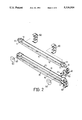
- FIG. 7 is a schematic view illustrating the use of the hazard-warning board constructed by the brake-light/hazard-warning board structure
- FIG. 8 is another perspective view illustrating another use of the hazard-warning board.
- FIG. 9 is a perspective view illustrating a further use of the hazard-warning board.
- a brake-light/hazard-warning board structure includes a first bar 10, a second bar 20, a third bar 30, and three connecting units 40 for connecting the three bars 10, 20, and 30 and providing a pivotal relationship therebetween.
- Each of the first, second, and third bars 10, 20, and 30 has a pivot means 11 at distal ends thereof.
- Each pivot means 11 has an arch 12 securely mounted thereto.
- First and second clicks 113 are formed on both sides of the arch 12, whose function will be described later.
- the connecting unit 40 is composed of a first member 41 and a second member 42.
- the first member 41 has substantially circular top and bottom portions and has a semi-circular teeth-like structure 420 recessed in each top and bottom portion in a periphery thereof for engaging with corresponding clips 113 on the pivot means 11.
- Two cylindrical protrusions 421, each with a first fastening hole 422 therein, are formed in the top and bottom portions and extend outward.
- the second member 42 also has substantially circular top and bottom portions and has a semi-circular teeth-like structure 410 recessed in each top and bottom portion in a periphery thereof for engaging with corresponding clicks 113 on the pivot means 11.
- Two second fastening holes 411 are formed in the second member 41, corresponding to the first fastening holes 422 in the first member 42 and through which screws 414 are passable.
- a first slot 413 is formed in the first and second members 41 and 42 of the connecting unit 40 for receiving a suction cup 50 when used as a brake light.
- a second slot 111 is formed in the pivot means 11 for receiving a suction cup 50 when used as a hazard-warning board.
- the connecting unit 40 and the pivot means 11 are in pivotal connection.
- an additional screw can be provided to fasten the whole structure, and pivot movement thereof is not allowed.
- a plurality of light emitting diodes (LED) 16 are provided on the first, second, and third bars 10, 20, and 30 and are electrically connected in series via wires 15, with two terminals 13 and 14 for electrically connecting in parallel with wires (not shown) pre-set in the brake lights 2 installed in a back end of a vehicle.
- LED light emitting diodes
- the brake-light/hazard-warning board structure according to the present invention is folded with two suction cups received in the connecting units, thereby attaching the whole brake-light/hazard-warning board structure to a rear window of a vehicle.
- the terminals of the brake light structure are electrically connected in parallel with pre-set wires of the brake lights of the vehicle.
- the brake-light/hazard-warning board structure according to the present invention is folded to a status shown in this figure.
- Two suction cups 50 are received in the first slots 413 in the connecting unit 40, thereby attaching the whole brake light structure to a rear window of a vehicle 1.
- two retaining means 60 are provided for retaining the three bars 10, 20, and 30 in a folded status. It is known that in this embodiment the two terminals 13 and 14 of the brake-light/hazard-warning board structure are electrically connected in parallel with pre-set wires of the brake lights 2 of the vehicle. Nevertheless, the brake light structure can be lowered and the two suction cups 50 can be received in the second slots 413 in the third bar 30, thereby attaching the brake light structure to a plate behind the rear seats in the vehicle 1.
- a telescopic rod 90 can be applied to assist in supporting of the hazard-warning board.
- the telescopic rod 90 has a hooked end for engaging with a further suction cup 50 on the trunk lid and an engaging block 91 at the other end for engaging with the first slot 413 on the uppermost connecting unit 40.
- the two terminals 13 and 14 of the hazard-warning board constructed by the brake-light/hazard-warning board structure are electrically connected with a power source, such as a cigarette lighter in the vehicle 1.
- a blinking means 70 can be provided in this embodiment so that the LEDs 16 provide a blinking effect.
- the wires are omitted here for clarity.
- FIG. 8 shows another embodiment of the present invention, in which the hazard-warning board constructed by the brake-light/hazard-warning board structure is hung on a tailgate of a truck by the hooked end 91.
- the two terminals 13 and 14 of the hazard-warning board are electrically connected with a power source, such as the cigarette lighter in the vehicle 1.
- a blinking means 70 can be provided in this embodiment so that the LEDs 16 provide a blinking effect.
- the wires are omitted here for clarity.
- FIG. 9 shows a further embodiment of the hazard-warning board, in which the hazard-warning board is securely mounted on a battery box 72, which in turn is mounted on a cross-support 82 via screws.
- the battery box has two knots 71 on an upper side thereof to be received in the second slots 111 of the bottom bar 10 of the hazard-warning board, thereby retaining the hazard-warning board on the battery box 72, which is a power source for the LEDs of the hazard-warning board.
- a blinking means can be provided in this embodiment so that the LEDs 16 provide a blinking effect.
Abstract
A brake-light/hazard-warning board structure includes a first bar, a second bar, a third bar each having a pivot member at distal ends thereof, and three connecting units for connecting pivot member of said first, second, and third bars and providing a pivotal relationship therebetween. A slot is formed in one of the pivot member and the connnecting unit for receiving a suction cup by which said brake-light/hazard-warning board structure is releasably mounted to a vehicle when used as a brake light. A number of light emitting diodes are provided on the first, second, and third bars and are electrically connected in series, with two terminals electrically connected with a power source.
Description
The present invention relates to a brake-light/hazard-warning board structure which can be used as either a third brake light or a hazard-warning board.
In high-traffic areas, brake lights are very important to warn other drivers when a car is braking. Drivers usually adapt, in addition to the installed factory-brake lights on a back end of a vehicle, an additional brake light for alarming following drivers. In other cases, drivers use an additional triangular hazard-warning board placed behind the vehicle when stopped at the side of the road. However, the hazard-warning board occupies a certain amount of trunk space.
To obviate and/or litigate the aforementioned problems, and to improve the "third" brake light structure's function, the present invention provides an improved structure which can be used as either as a brake light or a hazard-warning board.
According to the present invention, a brake-light/hazard-warning board structure includes a first bar, a second bar, a third bar, and three connecting units for connecting the three bars and providing a pivotal relationship therebetween.
Each of the first, second, and third bars has a pivot means at distal ends thereof. Each pivot means has an arch securely mounted thereto. First and second clicks are mounted on both sides of the arch.
The connecting unit is composed of a first member and a second member. The first member has substantially circular top and bottom portions and has a semi-circular teeth-like structure recessed in each top and bottom portion in a periphery thereof for engaging with corresponding clips on the pivot means. Two cylindrical protrusions, each with a first fastening hole therein, are formed in the top and bottom portions and extend outward. The second member also has substantially circular top and bottom portions and has a semi-circular teeth-like structure recessed in each top and bottom portion in a periphery thereof for engaging with corresponding clicks on the pivot means. Two second fastening holes are formed in the second member, corresponding to the first fastening holes and through which screws are passable. A first slot is formed in each connecting unit for receiving a suction cup when used as a brake light. A second slot is formed in the pivot means for receiving a suction cup when used as a hazard-warning board.
Due to the provision of the clicks and the semicircular teeth-like structure, the connecting unit and the pivot means are in pivotal connection. When the first, second, and third bars are pivoted to a desired position, for example, to form a hazard-warning board, screws can be provided to fasten the whole structure, and pivot movement thereof is not allowed.
A plurality of light emitting diodes (LED) are provided on the first, second, and third bars and are electrically connected in series via wires, with two terminals for electrically connecting in parallel with wires pre-set in the brake lights installed in a back end of a vehicle.
For providing a brake light function, the brake-light/hazard-warning board structure according to the present invention is folded with two suction cups received in the connecting units, thereby attaching the whole brake-light/hazard-warning board structure to a rear window of a vehicle. The terminals of the brake light structure are electrically connected in parallel with pre-set wires of the brake lights of the vehicle.
When the brake-light/hazard-warning board structure is constructed to form a hazard-warning board, two suction cups are now received in the first slots in the pivot means of a bottom bar thereof, thereby attaching the hazard-warning board on a trunk lid of the vehicle.
Other objects, advantages, and novel features of the invention will become more apparent from the following detailed description when taken in conjunction with the accompanying drawings.
FIG. 1 is a perspective view of a brake-light/hazard-warning board structure according to the present invention;
FIG. 2 is an exploded view of the brake-light/hazard-warning board structure in FIG. 1;
FIG. 3 is a perspective view in an enlarged scale showing the details of a pivot means and a connecting unit of the present invention;
FIG. 4 is a schematic side view showing engagement of the pivot means and the connecting unit;
FIG. 5 is a schematic view illustrating the use of cross-sectional view of the brake-light/hazard-warning board structure;
FIG. 6 is a perspective view of the brake-light/hazard-warning board structure assembled to form a hazard-warning board;
FIG. 7 is a schematic view illustrating the use of the hazard-warning board constructed by the brake-light/hazard-warning board structure;
FIG. 8 is another perspective view illustrating another use of the hazard-warning board; and
FIG. 9 is a perspective view illustrating a further use of the hazard-warning board.
Referring to the drawings and initially to FIGS. 1 through 4, a brake-light/hazard-warning board structure according to the present invention includes a first bar 10, a second bar 20, a third bar 30, and three connecting units 40 for connecting the three bars 10, 20, and 30 and providing a pivotal relationship therebetween.
Each of the first, second, and third bars 10, 20, and 30 has a pivot means 11 at distal ends thereof. Each pivot means 11 has an arch 12 securely mounted thereto. First and second clicks 113 (only one is shown) are formed on both sides of the arch 12, whose function will be described later.
Referring to FIG. 3, the connecting unit 40 is composed of a first member 41 and a second member 42. The first member 41 has substantially circular top and bottom portions and has a semi-circular teeth-like structure 420 recessed in each top and bottom portion in a periphery thereof for engaging with corresponding clips 113 on the pivot means 11. Two cylindrical protrusions 421, each with a first fastening hole 422 therein, are formed in the top and bottom portions and extend outward. The second member 42 also has substantially circular top and bottom portions and has a semi-circular teeth-like structure 410 recessed in each top and bottom portion in a periphery thereof for engaging with corresponding clicks 113 on the pivot means 11. Two second fastening holes 411 are formed in the second member 41, corresponding to the first fastening holes 422 in the first member 42 and through which screws 414 are passable. A first slot 413 is formed in the first and second members 41 and 42 of the connecting unit 40 for receiving a suction cup 50 when used as a brake light. A second slot 111 is formed in the pivot means 11 for receiving a suction cup 50 when used as a hazard-warning board.
As can be seen in FIG. 4, due to the provision of the clicks 113 and the semi-circular teeth- like structures 410 and 420, the connecting unit 40 and the pivot means 11 are in pivotal connection. When the first, second, and third bars 10, 20, and 30 are pivoted to a desired position, for example, to form a hazard-warning board, an additional screw can be provided to fasten the whole structure, and pivot movement thereof is not allowed.
A plurality of light emitting diodes (LED) 16 are provided on the first, second, and third bars 10, 20, and 30 and are electrically connected in series via wires 15, with two terminals 13 and 14 for electrically connecting in parallel with wires (not shown) pre-set in the brake lights 2 installed in a back end of a vehicle.
For providing a brake light function, the brake-light/hazard-warning board structure according to the present invention is folded with two suction cups received in the connecting units, thereby attaching the whole brake-light/hazard-warning board structure to a rear window of a vehicle. The terminals of the brake light structure are electrically connected in parallel with pre-set wires of the brake lights of the vehicle.
Referring now to FIG. 5, for providing a brake light function, the brake-light/hazard-warning board structure according to the present invention is folded to a status shown in this figure. Two suction cups 50 are received in the first slots 413 in the connecting unit 40, thereby attaching the whole brake light structure to a rear window of a vehicle 1. Additionally, two retaining means 60 (see FIG. 1 for detailed structure) are provided for retaining the three bars 10, 20, and 30 in a folded status. It is known that in this embodiment the two terminals 13 and 14 of the brake-light/hazard-warning board structure are electrically connected in parallel with pre-set wires of the brake lights 2 of the vehicle. Nevertheless, the brake light structure can be lowered and the two suction cups 50 can be received in the second slots 413 in the third bar 30, thereby attaching the brake light structure to a plate behind the rear seats in the vehicle 1.
Referring to FIGS. 6 and 7, in which the brake-light/hazard-warning board structure is constructed to form a hazard-warning board, two suction cups 50 are now received in the second slots 111 in the first bar 10, thereby attaching the hazard-warning board on a trunk lid of the vehicle. Additionally, a telescopic rod 90 can be applied to assist in supporting of the hazard-warning board. The telescopic rod 90 has a hooked end for engaging with a further suction cup 50 on the trunk lid and an engaging block 91 at the other end for engaging with the first slot 413 on the uppermost connecting unit 40. It is known that in this embodiment the two terminals 13 and 14 of the hazard-warning board constructed by the brake-light/hazard-warning board structure are electrically connected with a power source, such as a cigarette lighter in the vehicle 1. A blinking means 70 can be provided in this embodiment so that the LEDs 16 provide a blinking effect. The wires are omitted here for clarity.
FIG. 8 shows another embodiment of the present invention, in which the hazard-warning board constructed by the brake-light/hazard-warning board structure is hung on a tailgate of a truck by the hooked end 91. Again, in this embodiment the two terminals 13 and 14 of the hazard-warning board are electrically connected with a power source, such as the cigarette lighter in the vehicle 1. A blinking means 70 can be provided in this embodiment so that the LEDs 16 provide a blinking effect. The wires are omitted here for clarity.
FIG. 9 shows a further embodiment of the hazard-warning board, in which the hazard-warning board is securely mounted on a battery box 72, which in turn is mounted on a cross-support 82 via screws. The battery box has two knots 71 on an upper side thereof to be received in the second slots 111 of the bottom bar 10 of the hazard-warning board, thereby retaining the hazard-warning board on the battery box 72, which is a power source for the LEDs of the hazard-warning board. Again, a blinking means can be provided in this embodiment so that the LEDs 16 provide a blinking effect.
Although the invention has been explained in relation to its preferred embodiment, it is to be understood that many other possible modifications and variations can be made without departing the spirit and scope of the invention as hereinafter claimed.
Claims (8)
1. A brake-light/hazard-warning board structure comprising a first bar, a second bar, a third bar each having a pivot means at distal ends thereof, and three connecting units for connecting pivot means of said first, second, and third bars and providing a pivotal relationship therebetween, a slot being formed in at least one of said pivot means and said connecting units for receiving a mounting means by which said brake-light/hazard-warning board structure is releasably mounted to a vehicle when used as a brake light, a plurality of light-emitting diodes being provided on said first, second, and third bars and being electrically connected in series, with two terminals electrically connected with a power source.
2. The brake-light/hazard-warning board structure as claimed in claim 1, wherein said mounting means is a suction cup.
3. The brake-light/hazard-warning board structure as claimed in claim 1, wherein said terminals are electrically connected in parallel with wires pre-set in brake lights installed in a back end of a vehicle.
4. The brake-light/hazard-warning board structure as claimed in claim 1, wherein each pivot means has an arch securely mounted thereto, first and second clicks are formed on both sides of each said arch, each said connecting unit comprises a first member, a second member, and a means for releasably fastening said first and second members, said first member has first substantially circular top and bottom portions and has a first semi-circular teeth-like structure recessed in each said first circular top and bottom portion in aperiphery thereof for engaging with corresponding clicks on said pivot means, said second member has second substantially circular top and bottom portions and has a second semi-circular teeth-like structure recessed in each said second circular top and bottom portion in a periphery thereof for engaging with corresponding clicks on said pivot means.
5. The brake-light/hazard-warning board structure as claimed in claim 1, further comprising a retaining means for retaining said first, second, and third bars in a folded status when used as a brake light structure.
6. The brake-light/hazard-warning board structure as claimed in claim 2, wherein two said suction cups are received in said slots in a bottom bar of said brake-light/hazard-warning board structure when constructed to form a hazard-warning board, thereby attaching said hazard-warning board on a trunk lid of the vehicle.
7. The brake-light/hazard-warning board structure as claimed in claim 6, further comprising a telescopic rod for assisting in supporting of a hazard-warning board constructed by said brake-light/hazard-warning board structure, said telescopic rod having a first hooked end and a second end with an engaging block.
8. The brake-light/hazard-warning board structure as claimed in claim 6, wherein said first hooked end engages with a suction cup on a trunk lid of said vehicle, and said engaging block is received in said second slot of said hazard-warning board.
Priority Applications (1)
| Application Number | Priority Date | Filing Date | Title |
|---|---|---|---|
| US07/767,144 US5126926A (en) | 1991-09-27 | 1991-09-27 | Brake-light/hazard-warning board structure |
Applications Claiming Priority (1)
| Application Number | Priority Date | Filing Date | Title |
|---|---|---|---|
| US07/767,144 US5126926A (en) | 1991-09-27 | 1991-09-27 | Brake-light/hazard-warning board structure |
Publications (1)
| Publication Number | Publication Date |
|---|---|
| US5126926A true US5126926A (en) | 1992-06-30 |
Family
ID=25078614
Family Applications (1)
| Application Number | Title | Priority Date | Filing Date |
|---|---|---|---|
| US07/767,144 Expired - Fee Related US5126926A (en) | 1991-09-27 | 1991-09-27 | Brake-light/hazard-warning board structure |
Country Status (1)
| Country | Link |
|---|---|
| US (1) | US5126926A (en) |
Cited By (35)
| Publication number | Priority date | Publication date | Assignee | Title |
|---|---|---|---|---|
| US5255165A (en) * | 1992-09-24 | 1993-10-19 | Cail John M | Brake light assembly |
| US5278735A (en) * | 1993-03-19 | 1994-01-11 | Her Yih S | Distress signal lamp assembly |
| US5311412A (en) * | 1993-07-06 | 1994-05-10 | Yang Chang An | Structure of a variable triangular warning light on the third braking light in the rear turbulence plate of an automobile |
| EP0618109A1 (en) * | 1993-03-30 | 1994-10-05 | Securite Et Signalisation | Signal device for vehicles, particularly for urban vehicles |
| US5434758A (en) * | 1993-09-13 | 1995-07-18 | Zeidler; Reuven | Independent light replacement for vehicle |
| EP0683067A1 (en) * | 1994-05-16 | 1995-11-22 | Howard-Lloyde Enterprise Co., Ltd. | Braking lights for vehicle |
| GB2289995A (en) * | 1994-05-23 | 1995-12-06 | Yeh A Chien | Apparatus for indicating driving statuses of a vehicle |
| EP0689960A1 (en) * | 1994-07-02 | 1996-01-03 | Howard-Lloyde Enterprise Co., Ltd. | Foldable triangular warning light mounted on the third braking light of an automobile |
| US5558427A (en) * | 1994-05-25 | 1996-09-24 | Yang; Chang A. | Base structure for a three section type third braking light which can be converted into a triangular failure warning light |
| US5566485A (en) * | 1995-11-24 | 1996-10-22 | Chang; Shin-Shui | Car-used distress sign |
| US5606309A (en) * | 1995-01-31 | 1997-02-25 | Smith; Frank | Road hazard warning apparatus |
| GB2309113A (en) * | 1996-01-15 | 1997-07-16 | Robert Lucas | Vehicle hazard warning system |
| US5764141A (en) * | 1997-02-06 | 1998-06-09 | Chang; Jih-Cheng | Motor vehicle warning signal light assembly |
| US6008732A (en) * | 1992-12-31 | 1999-12-28 | Lam; Peter Ar-Fu | Motor vehicle display apparatus |
| US20020048174A1 (en) * | 1999-08-04 | 2002-04-25 | Pederson John C. | LED double light bar and warning light signal |
| US6509832B1 (en) | 1998-09-15 | 2003-01-21 | Gentex Corporation | Systems and components for enhancing rear vision from a vehicle |
| US20030039126A1 (en) * | 2001-08-22 | 2003-02-27 | Fox Ronald M. | Multifunctional third brake light |
| US20030103141A1 (en) * | 1997-12-31 | 2003-06-05 | Bechtel Jon H. | Vehicle vision system |
| US20060103543A1 (en) * | 2004-11-02 | 2006-05-18 | Chang-Hao Chen | Mobile signal light set |
| US20060227543A1 (en) * | 2005-04-11 | 2006-10-12 | Li-Yen Lu | Warning device |
| US20070041110A1 (en) * | 2005-08-22 | 2007-02-22 | Gentex Corporation | Vehicular rearview components and assemblies |
| US20080218329A1 (en) * | 2007-03-08 | 2008-09-11 | Fan Shen Hsi | Vehicle breakdown warning sign |
| US7834750B1 (en) | 2005-11-22 | 2010-11-16 | Hertz Allen D | Pickup truck tailgate safety light system |
| US20110043313A1 (en) * | 2004-12-27 | 2011-02-24 | Masao Hosokawa | Power distribution transformer and tank therefor |
| CN102479471A (en) * | 2010-11-25 | 2012-05-30 | 何昌宪 | Improved structure of warning tripod |
| US8552852B1 (en) | 2005-11-22 | 2013-10-08 | Allen D Hertz | Trailer hitch receiver safety light system |
| US9234381B2 (en) | 2013-01-07 | 2016-01-12 | WexEnergy LLC | Supplemental window for fenestration |
| US9663983B2 (en) | 2013-01-07 | 2017-05-30 | WexEnergy LLC | Frameless supplemental window for fenestration incorporating infiltration blockers |
| US9845636B2 (en) | 2013-01-07 | 2017-12-19 | WexEnergy LLC | Frameless supplemental window for fenestration |
| US10196850B2 (en) | 2013-01-07 | 2019-02-05 | WexEnergy LLC | Frameless supplemental window for fenestration |
| US10346999B2 (en) | 2013-01-07 | 2019-07-09 | Wexenergy Innovations Llc | System and method of measuring distances related to an object utilizing ancillary objects |
| US10533364B2 (en) | 2017-05-30 | 2020-01-14 | WexEnergy LLC | Frameless supplemental window for fenestration |
| US10894512B2 (en) | 2019-04-11 | 2021-01-19 | Gregory J. Phillips | Side-facing side view mirror brake lights |
| US11110748B1 (en) * | 2019-12-17 | 2021-09-07 | Charles Scott | Illuminated vehicle distress sign |
| US11370270B2 (en) * | 2018-01-02 | 2022-06-28 | Ford Global Technologies, Llc | Air-guiding element and motor vehicle |
Citations (8)
| Publication number | Priority date | Publication date | Assignee | Title |
|---|---|---|---|---|
| US3783267A (en) * | 1972-07-21 | 1974-01-01 | R Thomas | Extendible vehicle light mount |
| US4180010A (en) * | 1975-12-18 | 1979-12-25 | Mcdermott Julian A | Mount for vehicular warning lights |
| US4808968A (en) * | 1987-10-26 | 1989-02-28 | Caine Harold A | Automotive warning and brake light arrangement |
| US4809138A (en) * | 1988-06-13 | 1989-02-28 | Stovall Fred J | Taillight assembly for boat trailers |
| US4825191A (en) * | 1986-07-29 | 1989-04-25 | Ching Hwei Lan | Automobile multi-purpose auxiliary indicator |
| US4835515A (en) * | 1987-10-13 | 1989-05-30 | Mcdermott Julian A | Vehicle-warning signal light |
| US5016145A (en) * | 1989-10-12 | 1991-05-14 | Singleton Kent A | Illuminated display vehicle ornament |
| US5041813A (en) * | 1990-01-25 | 1991-08-20 | Chang Jih Cheng | "Automobile disabled" sign |
-
1991
- 1991-09-27 US US07/767,144 patent/US5126926A/en not_active Expired - Fee Related
Patent Citations (8)
| Publication number | Priority date | Publication date | Assignee | Title |
|---|---|---|---|---|
| US3783267A (en) * | 1972-07-21 | 1974-01-01 | R Thomas | Extendible vehicle light mount |
| US4180010A (en) * | 1975-12-18 | 1979-12-25 | Mcdermott Julian A | Mount for vehicular warning lights |
| US4825191A (en) * | 1986-07-29 | 1989-04-25 | Ching Hwei Lan | Automobile multi-purpose auxiliary indicator |
| US4835515A (en) * | 1987-10-13 | 1989-05-30 | Mcdermott Julian A | Vehicle-warning signal light |
| US4808968A (en) * | 1987-10-26 | 1989-02-28 | Caine Harold A | Automotive warning and brake light arrangement |
| US4809138A (en) * | 1988-06-13 | 1989-02-28 | Stovall Fred J | Taillight assembly for boat trailers |
| US5016145A (en) * | 1989-10-12 | 1991-05-14 | Singleton Kent A | Illuminated display vehicle ornament |
| US5041813A (en) * | 1990-01-25 | 1991-08-20 | Chang Jih Cheng | "Automobile disabled" sign |
Cited By (53)
| Publication number | Priority date | Publication date | Assignee | Title |
|---|---|---|---|---|
| US5255165A (en) * | 1992-09-24 | 1993-10-19 | Cail John M | Brake light assembly |
| US6008732A (en) * | 1992-12-31 | 1999-12-28 | Lam; Peter Ar-Fu | Motor vehicle display apparatus |
| US5278735A (en) * | 1993-03-19 | 1994-01-11 | Her Yih S | Distress signal lamp assembly |
| EP0618109A1 (en) * | 1993-03-30 | 1994-10-05 | Securite Et Signalisation | Signal device for vehicles, particularly for urban vehicles |
| US5311412A (en) * | 1993-07-06 | 1994-05-10 | Yang Chang An | Structure of a variable triangular warning light on the third braking light in the rear turbulence plate of an automobile |
| US5434758A (en) * | 1993-09-13 | 1995-07-18 | Zeidler; Reuven | Independent light replacement for vehicle |
| EP0683067A1 (en) * | 1994-05-16 | 1995-11-22 | Howard-Lloyde Enterprise Co., Ltd. | Braking lights for vehicle |
| ES2112139A1 (en) * | 1994-05-23 | 1998-03-16 | Yeh A Chien | Apparatus for indicating driving status of a vehicle |
| GB2289995A (en) * | 1994-05-23 | 1995-12-06 | Yeh A Chien | Apparatus for indicating driving statuses of a vehicle |
| US5558427A (en) * | 1994-05-25 | 1996-09-24 | Yang; Chang A. | Base structure for a three section type third braking light which can be converted into a triangular failure warning light |
| EP0689960A1 (en) * | 1994-07-02 | 1996-01-03 | Howard-Lloyde Enterprise Co., Ltd. | Foldable triangular warning light mounted on the third braking light of an automobile |
| US5606309A (en) * | 1995-01-31 | 1997-02-25 | Smith; Frank | Road hazard warning apparatus |
| US5566485A (en) * | 1995-11-24 | 1996-10-22 | Chang; Shin-Shui | Car-used distress sign |
| GB2309113B (en) * | 1996-01-15 | 2000-09-13 | Robert Lucas | Vehicle hazard warning device |
| GB2309113A (en) * | 1996-01-15 | 1997-07-16 | Robert Lucas | Vehicle hazard warning system |
| US6550949B1 (en) | 1996-06-13 | 2003-04-22 | Gentex Corporation | Systems and components for enhancing rear vision from a vehicle |
| US5764141A (en) * | 1997-02-06 | 1998-06-09 | Chang; Jih-Cheng | Motor vehicle warning signal light assembly |
| US7567291B2 (en) | 1997-12-31 | 2009-07-28 | Gentex Corporation | Vehicle vision system |
| US20030103141A1 (en) * | 1997-12-31 | 2003-06-05 | Bechtel Jon H. | Vehicle vision system |
| US6672745B1 (en) | 1998-09-15 | 2004-01-06 | Gentex Corporation | Systems and components for enhancing rear vision from a vehicle |
| US20040160786A1 (en) * | 1998-09-15 | 2004-08-19 | Bauer Frederick T. | Systems and components for enhancing rear vision from a vehicle |
| US20070017642A1 (en) * | 1998-09-15 | 2007-01-25 | Bauer Frederick T | Systems and Components for Enhancing Rear Vision from a Vehicle |
| US7111968B2 (en) | 1998-09-15 | 2006-09-26 | Gentex Corporation | Systems and components for enhancing rear vision from a vehicle |
| US7568823B2 (en) | 1998-09-15 | 2009-08-04 | Gentex Corporation | Systems and components for enhancing rear vision from a vehicle |
| US6509832B1 (en) | 1998-09-15 | 2003-01-21 | Gentex Corporation | Systems and components for enhancing rear vision from a vehicle |
| US6623151B2 (en) * | 1999-08-04 | 2003-09-23 | 911Ep, Inc. | LED double light bar and warning light signal |
| US20020048174A1 (en) * | 1999-08-04 | 2002-04-25 | Pederson John C. | LED double light bar and warning light signal |
| US20030039126A1 (en) * | 2001-08-22 | 2003-02-27 | Fox Ronald M. | Multifunctional third brake light |
| US6799873B2 (en) * | 2001-08-22 | 2004-10-05 | Ronald M. Fox | Multifunctional third brake light |
| US20060103543A1 (en) * | 2004-11-02 | 2006-05-18 | Chang-Hao Chen | Mobile signal light set |
| US7142103B2 (en) * | 2004-11-02 | 2006-11-28 | Chang-Hao Chen | Mobile signal light set |
| US8143985B2 (en) * | 2004-12-27 | 2012-03-27 | Hitachi Industrial Equipment Systems Co., Ltd. | Power distribution transformer and tank therefor |
| US8432244B2 (en) | 2004-12-27 | 2013-04-30 | Hitachi Industrial Equipment Systems Co., Ltd. | Power distribution transformer and tank therefor |
| US20110043313A1 (en) * | 2004-12-27 | 2011-02-24 | Masao Hosokawa | Power distribution transformer and tank therefor |
| US20060227543A1 (en) * | 2005-04-11 | 2006-10-12 | Li-Yen Lu | Warning device |
| US20070041110A1 (en) * | 2005-08-22 | 2007-02-22 | Gentex Corporation | Vehicular rearview components and assemblies |
| US7488083B2 (en) | 2005-08-22 | 2009-02-10 | Gentex Corporation | Vehicular rearview components and assemblies |
| US8552852B1 (en) | 2005-11-22 | 2013-10-08 | Allen D Hertz | Trailer hitch receiver safety light system |
| US7834750B1 (en) | 2005-11-22 | 2010-11-16 | Hertz Allen D | Pickup truck tailgate safety light system |
| US8854201B1 (en) | 2005-11-22 | 2014-10-07 | Allen D. Hertz | Detachable vehicle taillight and flashlight combination |
| US20080218329A1 (en) * | 2007-03-08 | 2008-09-11 | Fan Shen Hsi | Vehicle breakdown warning sign |
| CN102479471A (en) * | 2010-11-25 | 2012-05-30 | 何昌宪 | Improved structure of warning tripod |
| CN102479471B (en) * | 2010-11-25 | 2014-06-04 | 何昌宪 | Improved structure of warning tripod |
| US9663983B2 (en) | 2013-01-07 | 2017-05-30 | WexEnergy LLC | Frameless supplemental window for fenestration incorporating infiltration blockers |
| US9234381B2 (en) | 2013-01-07 | 2016-01-12 | WexEnergy LLC | Supplemental window for fenestration |
| US9845636B2 (en) | 2013-01-07 | 2017-12-19 | WexEnergy LLC | Frameless supplemental window for fenestration |
| US10196850B2 (en) | 2013-01-07 | 2019-02-05 | WexEnergy LLC | Frameless supplemental window for fenestration |
| US10346999B2 (en) | 2013-01-07 | 2019-07-09 | Wexenergy Innovations Llc | System and method of measuring distances related to an object utilizing ancillary objects |
| US10501981B2 (en) | 2013-01-07 | 2019-12-10 | WexEnergy LLC | Frameless supplemental window for fenestration |
| US10533364B2 (en) | 2017-05-30 | 2020-01-14 | WexEnergy LLC | Frameless supplemental window for fenestration |
| US11370270B2 (en) * | 2018-01-02 | 2022-06-28 | Ford Global Technologies, Llc | Air-guiding element and motor vehicle |
| US10894512B2 (en) | 2019-04-11 | 2021-01-19 | Gregory J. Phillips | Side-facing side view mirror brake lights |
| US11110748B1 (en) * | 2019-12-17 | 2021-09-07 | Charles Scott | Illuminated vehicle distress sign |
Similar Documents
| Publication | Publication Date | Title |
|---|---|---|
| US5126926A (en) | Brake-light/hazard-warning board structure | |
| US4857890A (en) | Safety rear license plate frame | |
| US4534496A (en) | Luggage carrier with illuminating means | |
| US6604834B2 (en) | Electroluminescent surface illuminator device | |
| US3800430A (en) | Multiple purpose vehicle signal device | |
| CA2182533A1 (en) | Front grille mounting construction | |
| US6561689B1 (en) | Trapped LED CHMSL with living hinge | |
| KR890004907A (en) | Modular Rear Deck Lighting Cluster | |
| US5541891A (en) | Distance sensing device | |
| US3005089A (en) | Indicating device for a vehicle | |
| US6354723B1 (en) | Lighted footrest for motorcycle | |
| WO2018026534A1 (en) | Truck bed rail light assembly | |
| USD415296S (en) | Light bar for truck | |
| US6935820B2 (en) | Lighted tie down anchor and method for using same | |
| US20220203914A1 (en) | Lighted vehicle step pad and vehicle light source | |
| US6561686B1 (en) | Vehicle light mount | |
| JPH0513643Y2 (en) | ||
| US1866185A (en) | Automobile signal | |
| US6808300B2 (en) | Brake light | |
| EP1389563A2 (en) | Illuminant for turbulent flow plate | |
| KR200285008Y1 (en) | A lighting system for cultivator | |
| JP3015136U (en) | Bicycle alarm | |
| JPH0436994Y2 (en) | ||
| KR960022125A (en) | Fixed structure of car spare tire | |
| KR970042007A (en) | Fixed structure of car spare tire |
Legal Events
| Date | Code | Title | Description |
|---|---|---|---|
| REMI | Maintenance fee reminder mailed | ||
| LAPS | Lapse for failure to pay maintenance fees | ||
| FP | Expired due to failure to pay maintenance fee |
Effective date: 19960703 |
|
| STCH | Information on status: patent discontinuation |
Free format text: PATENT EXPIRED DUE TO NONPAYMENT OF MAINTENANCE FEES UNDER 37 CFR 1.362 |