US5131649A - Multiple output sheet inverter - Google Patents
Multiple output sheet inverter Download PDFInfo
- Publication number
- US5131649A US5131649A US07/635,834 US63583491A US5131649A US 5131649 A US5131649 A US 5131649A US 63583491 A US63583491 A US 63583491A US 5131649 A US5131649 A US 5131649A
- Authority
- US
- United States
- Prior art keywords
- sheet
- nip
- nips
- directing
- Prior art date
- Legal status (The legal status is an assumption and is not a legal conclusion. Google has not performed a legal analysis and makes no representation as to the accuracy of the status listed.)
- Expired - Lifetime
Links
- 230000008859 change Effects 0.000 claims description 13
- 230000007246 mechanism Effects 0.000 claims description 11
- 238000010586 diagram Methods 0.000 description 8
- 230000002457 bidirectional effect Effects 0.000 description 3
- 238000000034 method Methods 0.000 description 1
- 108091008695 photoreceptors Proteins 0.000 description 1
- 230000008569 process Effects 0.000 description 1
- 238000004080 punching Methods 0.000 description 1
Images

Classifications
-
- G—PHYSICS
- G03—PHOTOGRAPHY; CINEMATOGRAPHY; ANALOGOUS TECHNIQUES USING WAVES OTHER THAN OPTICAL WAVES; ELECTROGRAPHY; HOLOGRAPHY
- G03G—ELECTROGRAPHY; ELECTROPHOTOGRAPHY; MAGNETOGRAPHY
- G03G15/00—Apparatus for electrographic processes using a charge pattern
- G03G15/65—Apparatus which relate to the handling of copy material
- G03G15/6555—Handling of sheet copy material taking place in a specific part of the copy material feeding path
- G03G15/6579—Refeeding path for composite copying
-
- B—PERFORMING OPERATIONS; TRANSPORTING
- B65—CONVEYING; PACKING; STORING; HANDLING THIN OR FILAMENTARY MATERIAL
- B65H—HANDLING THIN OR FILAMENTARY MATERIAL, e.g. SHEETS, WEBS, CABLES
- B65H15/00—Overturning articles
- B65H15/004—Overturning articles employing rollers
-
- G—PHYSICS
- G03—PHOTOGRAPHY; CINEMATOGRAPHY; ANALOGOUS TECHNIQUES USING WAVES OTHER THAN OPTICAL WAVES; ELECTROGRAPHY; HOLOGRAPHY
- G03G—ELECTROGRAPHY; ELECTROPHOTOGRAPHY; MAGNETOGRAPHY
- G03G15/00—Apparatus for electrographic processes using a charge pattern
- G03G15/22—Apparatus for electrographic processes using a charge pattern involving the combination of more than one step according to groups G03G13/02 - G03G13/20
- G03G15/23—Apparatus for electrographic processes using a charge pattern involving the combination of more than one step according to groups G03G13/02 - G03G13/20 specially adapted for copying both sides of an original or for copying on both sides of a recording or image-receiving material
- G03G15/231—Arrangements for copying on both sides of a recording or image-receiving material
- G03G15/232—Arrangements for copying on both sides of a recording or image-receiving material using a single reusable electrographic recording member
- G03G15/234—Arrangements for copying on both sides of a recording or image-receiving material using a single reusable electrographic recording member by inverting and refeeding the image receiving material with an image on one face to the recording member to transfer a second image on its second face, e.g. by using a duplex tray; Details of duplex trays or inverters
-
- B—PERFORMING OPERATIONS; TRANSPORTING
- B65—CONVEYING; PACKING; STORING; HANDLING THIN OR FILAMENTARY MATERIAL
- B65H—HANDLING THIN OR FILAMENTARY MATERIAL, e.g. SHEETS, WEBS, CABLES
- B65H2301/00—Handling processes for sheets or webs
- B65H2301/30—Orientation, displacement, position of the handled material
- B65H2301/33—Modifying, selecting, changing orientation
- B65H2301/333—Inverting
- B65H2301/3331—Involving forward reverse transporting means
- B65H2301/33312—Involving forward reverse transporting means forward reverse rollers pairs
-
- B—PERFORMING OPERATIONS; TRANSPORTING
- B65—CONVEYING; PACKING; STORING; HANDLING THIN OR FILAMENTARY MATERIAL
- B65H—HANDLING THIN OR FILAMENTARY MATERIAL, e.g. SHEETS, WEBS, CABLES
- B65H2301/00—Handling processes for sheets or webs
- B65H2301/30—Orientation, displacement, position of the handled material
- B65H2301/33—Modifying, selecting, changing orientation
- B65H2301/333—Inverting
- B65H2301/3332—Tri-rollers type
-
- G—PHYSICS
- G03—PHOTOGRAPHY; CINEMATOGRAPHY; ANALOGOUS TECHNIQUES USING WAVES OTHER THAN OPTICAL WAVES; ELECTROGRAPHY; HOLOGRAPHY
- G03G—ELECTROGRAPHY; ELECTROPHOTOGRAPHY; MAGNETOGRAPHY
- G03G2215/00—Apparatus for electrophotographic processes
- G03G2215/00362—Apparatus for electrophotographic processes relating to the copy medium handling
- G03G2215/00367—The feeding path segment where particular handling of the copy medium occurs, segments being adjacent and non-overlapping. Each segment is identified by the most downstream point in the segment, so that for instance the segment labelled "Fixing device" is referring to the path between the "Transfer device" and the "Fixing device"
- G03G2215/00417—Post-fixing device
- G03G2215/00421—Discharging tray, e.g. devices stabilising the quality of the copy medium, postfixing-treatment, inverting, sorting
-
- G—PHYSICS
- G03—PHOTOGRAPHY; CINEMATOGRAPHY; ANALOGOUS TECHNIQUES USING WAVES OTHER THAN OPTICAL WAVES; ELECTROGRAPHY; HOLOGRAPHY
- G03G—ELECTROGRAPHY; ELECTROPHOTOGRAPHY; MAGNETOGRAPHY
- G03G2215/00—Apparatus for electrophotographic processes
- G03G2215/00362—Apparatus for electrophotographic processes relating to the copy medium handling
- G03G2215/00367—The feeding path segment where particular handling of the copy medium occurs, segments being adjacent and non-overlapping. Each segment is identified by the most downstream point in the segment, so that for instance the segment labelled "Fixing device" is referring to the path between the "Transfer device" and the "Fixing device"
- G03G2215/00417—Post-fixing device
- G03G2215/0043—Refeeding path
- G03G2215/00438—Inverter of refeeding path
-
- G—PHYSICS
- G03—PHOTOGRAPHY; CINEMATOGRAPHY; ANALOGOUS TECHNIQUES USING WAVES OTHER THAN OPTICAL WAVES; ELECTROGRAPHY; HOLOGRAPHY
- G03G—ELECTROGRAPHY; ELECTROPHOTOGRAPHY; MAGNETOGRAPHY
- G03G2215/00—Apparatus for electrophotographic processes
- G03G2215/00362—Apparatus for electrophotographic processes relating to the copy medium handling
- G03G2215/00535—Stable handling of copy medium
- G03G2215/00675—Mechanical copy medium guiding means, e.g. mechanical switch
-
- G—PHYSICS
- G03—PHOTOGRAPHY; CINEMATOGRAPHY; ANALOGOUS TECHNIQUES USING WAVES OTHER THAN OPTICAL WAVES; ELECTROGRAPHY; HOLOGRAPHY
- G03G—ELECTROGRAPHY; ELECTROPHOTOGRAPHY; MAGNETOGRAPHY
- G03G2215/00—Apparatus for electrophotographic processes
- G03G2215/00362—Apparatus for electrophotographic processes relating to the copy medium handling
- G03G2215/00535—Stable handling of copy medium
- G03G2215/00687—Handling details
- G03G2215/007—Inverter not for refeeding purposes
-
- Y—GENERAL TAGGING OF NEW TECHNOLOGICAL DEVELOPMENTS; GENERAL TAGGING OF CROSS-SECTIONAL TECHNOLOGIES SPANNING OVER SEVERAL SECTIONS OF THE IPC; TECHNICAL SUBJECTS COVERED BY FORMER USPC CROSS-REFERENCE ART COLLECTIONS [XRACs] AND DIGESTS
- Y10—TECHNICAL SUBJECTS COVERED BY FORMER USPC
- Y10S—TECHNICAL SUBJECTS COVERED BY FORMER USPC CROSS-REFERENCE ART COLLECTIONS [XRACs] AND DIGESTS
- Y10S271/00—Sheet feeding or delivering
- Y10S271/902—Reverse direction of sheet movement
Definitions
- the present invention relates to improvements in copy machine architecture including a multiple output inverter that serves to interchange the trail edge of a sheet with the lead edge while interchanging the bottom side of the sheet with the top side.
- the inverter also acts as a gating station to direct sheet to a proper paper path.
- Inverters are used in copiers to enable automatic duplex and color highlight copying.
- the main function of an inverter is to interchange the trail edge of the sheet with the lead edge, while interchanging the bottom side of the sheet with the top side. This general concept is depicted in FIG. 8.
- Such gating devices include a movable guide at a crossroad for directing a sheet into one of a number of paper paths. Gates do not invert copy sheets, rather, they serve to direct sheets to a desired path.
- An object of the present invention is to improve copier architecture to make copiers smaller and to eliminate unnecessary paper paths.
- Another object of the present invention is to provide highly reliable sheet inverter.
- the sheet feeding apparatus of the present invention includes a sheet pocket having a first end and a second end, roller means spaced a predetermined distance from the first end and including a plurality of sheet-feeder nips, one of said nips for directing a sheet into said first end of said sheet pocket, and at least one other of said nips for directing a sheet out of said first end of said sheet pocket, and bypass means for selectively permitting a sheet to exit said sheet pocket via said second end thereof.
- FIG. 1 is a schematic diagram of a bidirectional inverter/gating station in accordance with the present invention
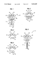
- FIG. 2 is a schematic diagram depicting the motion of laterally moving shuttle shown in FIG. 1;
- FIG. 3 is a schematic diagram of a pivoting baffle direction change mechanism in accordance with the present invention.
- FIG. 4 is a schematic diagram of a pivoting roller direction change mechanism in accordance with the present invention.
- FIG. 5 is a schematic diagram depicting a bidirectional inverter without a sheet bypass, in accordance with the present invention.
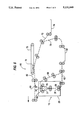
- FIG. 6 is a schematic diagram of copy machine architecture in accordance with the present invention, employing the bidirectional inverter/gating station of FIG. 1;
- FIG. 7 is a schematic diagram depicting copy machine architecture employing a tri-roller inverter/gating station in accordance with the present invention.
- FIG. 8 is a schematic diagram generally depicting the function of sheet inverters.
- a sheet feeding apparatus having a sheet pocket with a first end and a second end.
- inverter/gating station 10 includes baffles 12 and 14 which cooperate to define sheet pocket 16.
- a pair of reversing rollers 22 and 24 are disposed adjacent the first end 18 of sheet pocket 16, and a pair of bypass rollers 26 and 28 are disposed adjacent the second end 20 of sheet pocket 16. Rollers 22, 24, 26, and 28 cooperate to control the movement of copy sheets into and out of sheet pocket 16.
- roller means spaced a predetermined distance from the first end of the sheet pocket and including a plurality of sheet feeder nips, one of the nips for directing a sheet into the first end of the sheet pocket, and at least one other of the nips for directing a sheet out of the first end of the sheet pocket.
- roller means includes rollers 30, 32, 34 and 36. cooperating to define inlet nip 33 and two exit nips, 31 and 35. Roller 32 rotates clockwise and roller 34 rotates counterclockwise so that a sheet disposed in nip 33 therebetween is forwarded into sheet pocket 16.
- Roller 30 rotates counterclockwise and roller 32 rotates clockwise so that a sheet grabbed by first exit nip 31 is forwarded out of the first end 18 of sheet pocket 16 in a first direction.
- roller 36 rotates clockwise to form a second exit nip 35 between rollers 3 and 36. A sheet grabbed by nip 35 is therefore forwarded out of the first end 18 of sheet pocket 16 in a second direction.
- direction change mechanism 38 includes reversing rollers 22 and 24 that change direction depending upon desired sheet travel.
- direction change mechanism 38 includes reversing rollers 22 and 24 that change direction depending upon desired sheet travel.
- FIGS. 2-4 there are a number of alternative direction change mechanisms in accordance with the present invention, and as depicted in FIGS. 2-4.
- reversing rollers 22 and 24 are mounted on a shuttle 46 that moves laterally in the direction of line 40. Initially, shuttle 46 is disposed so that the nip 23 between reversing rollers 22 and 24 is positioned directly beneath inlet nip 33 between rollers 32 and 34. Reversing roller 22 initially rotates clockwise while reversing roller 24 initially rotates counterclockwise to forward a sheet into sheet pocket 16. When a sheet in sheet pocket 16 is to be forwarded out of one of the first or second exit nips, shuttle 46 is moved in a lateral direction towards the desired nip and the rotation of reversing rollers 22 and 24 is reversed.
- Baffles 42 and 44 may be provided between rollers 30, 32, 34 and 36, and reversing rollers 22 and 24 to aid in directing sheets between inlet 33, sheet pocket 16 and exit nips 31 and 35. However, depending upon specific design requirements, baffles 42 and 44 may be eliminated as shown in FIG. 1.
- direction change mechanism 38 may include pivoting baffles 48 and 50.
- baffles 48 and 50 are displaced laterally as they pivot along an arc 52. Pivotal movement of baffles 48 and 50 serves to direct a sheet exiting sheet pocket 16 toward a desired exit nip.
- direction change mechanism 38 may include pivoting rollers 54 and 56. Similar to reversing roller 22 and 24, pivoting rolls 54 and 56 change direction depending upon whether a sheet is entering through the inlet nip 33 or exiting through one of the two exit nips 31 or 35. However, pivoting rolls 54 and 56 are displaced laterally when pivoting rolls 54 and 56 are pivoted in the direction of arc 58. This pivotal movement of pivoting rolls 54 and 56 directs a sheet leaving sheet pocket 16 toward a desired exit nip.
- bypass means for selectively permitting a sheet to exit the sheet pocket via the second end thereof.
- bypass means includes bypass rollers 26 and 28 disposed adjacent the second end 20 of sheet pocket 16.
- a controller may direct bypass rollers 26 and 28 to forward a sheet out of the second end 20 of sheet pocket 16 to provide a bypass exit from sheet pocket 16 alternate to first an second exit nips 31 and 35.
- the inverter/gating station 10 described above enables unique copier architecture such as the architecture depicted in FIG. 6.
- paper path 62 connects second end 20 of inverter/gating station 10 with duplex tray 64
- a second sheet path 66 extends from exit nip 35 to duplex tray 64.
- a third sheet path 68 extends from exit nip 31 to a finisher.
- the finisher may include a binding device such as a stapler or a clip fitting unit, a hole punching device, or may merely be an output tray for collecting finished copy sheets.
- a fourth sheet path 70 extends from duplex tray 64 to inlet nip 33, and a fifth sheet path 72 connects copy sheet source 74, such as a sheet feeder, to fourth sheet path 70.
- An image transfer station 78 of a photoreceptor belt circuit 76 is positioned adjacent fourth sheet path 70. Thus, when a sheet from copy sheet source 74 passes transfer station 78, an image developed by photoreceptor circuit 76 is transferred to the copy sheet.
- gate 80 disposed downstream of fuser rollers 82 directs the copy sheet directly to a finisher. Otherwise, for multiple pass copies, double-sided copies and inverted copies, gate 80 directs the copy sheet into inlet nip 33 of inverter/gating station 10.
- a controller (not shown) directs a copy sheet out of inverter/gating station 10 through exit nip 35.
- the copy sheet then proceeds to duplex tray 64 and back to transfer station 78 where a developed image is printed on the opposite side of the copy sheet at transfer station 78.
- a copy sheet exits inverter/gating station 10 through bypass rollers 26 and 28. After the sheet leaves duplex tray 64, it returns to transfer station 78 where a second image may be superimposed over the first image.
- invert copy sheets can be directed into inverter/gating station 10 through inlet nip 33 and directed out of inverter/gating station 10 through exit nip 31.
- a tri-roller inverter 84 may be employed along with an additional gate 86 to accomplish a function similar to the function achieved by the copier disclosed in FIG. 6.
- gate 86 selectively directs copy sheets exiting through exit nip 88 to either the duplex tray or the finisher.
- spring backstop 90 may be disposed about baffles 12 and 14 of sheet pocket 16. When a sheet enters sheet pocket 16, spring backstop 90 absorbs the energy of the incoming sheet, supplies back energy to the outgoing sheet, and accommodates appropriate sheet length between inlet nip 33 and the rear end 92 of backstop 90 for various paper sizes.
- the inversion process with the embodiment shown in FIG. 5 can be described as follows.
- a sheet is fed through inlet nip 33 into sheet pocket 16.
- spring backstop 90 As a lead edge of the sheet comes into contact with spring backstop 90, the copy sheet is decelerated to a stop, its direction is reversed, and the sheet is accelerated and directed to a desired exit nip by direction change mechanism 38.
Abstract
Description
Claims (15)
Priority Applications (4)
| Application Number | Priority Date | Filing Date | Title |
|---|---|---|---|
| US07/635,834 US5131649A (en) | 1991-01-03 | 1991-01-03 | Multiple output sheet inverter |
| JP34422291A JP3243765B2 (en) | 1991-01-03 | 1991-12-26 | Paper feeder |
| EP92300014A EP0494108B1 (en) | 1991-01-03 | 1992-01-02 | A multiple output sheet inverter |
| DE69209665T DE69209665T2 (en) | 1991-01-03 | 1992-01-02 | Sheet turning device with multiple output directions |
Applications Claiming Priority (1)
| Application Number | Priority Date | Filing Date | Title |
|---|---|---|---|
| US07/635,834 US5131649A (en) | 1991-01-03 | 1991-01-03 | Multiple output sheet inverter |
Publications (1)
| Publication Number | Publication Date |
|---|---|
| US5131649A true US5131649A (en) | 1992-07-21 |
Family
ID=24549299
Family Applications (1)
| Application Number | Title | Priority Date | Filing Date |
|---|---|---|---|
| US07/635,834 Expired - Lifetime US5131649A (en) | 1991-01-03 | 1991-01-03 | Multiple output sheet inverter |
Country Status (4)
| Country | Link |
|---|---|
| US (1) | US5131649A (en) |
| EP (1) | EP0494108B1 (en) |
| JP (1) | JP3243765B2 (en) |
| DE (1) | DE69209665T2 (en) |
Cited By (16)
| Publication number | Priority date | Publication date | Assignee | Title |
|---|---|---|---|---|
| US5265864A (en) * | 1992-04-02 | 1993-11-30 | Xerox Corporation | Inverter with a friction/corrugating driver |
| US5273273A (en) * | 1992-11-27 | 1993-12-28 | Eastman Kodak Company | Sheet inverting mechanism having dual drive assemblies |
| US5690325A (en) * | 1995-04-07 | 1997-11-25 | Sharp Kabushiki Kaisha | Paper-reversing apparatus for use in providing two-sided copies |
| US5887868A (en) * | 1993-12-09 | 1999-03-30 | Xerox Corporation | Drive system for rollers |
| US6024682A (en) * | 1998-11-23 | 2000-02-15 | Xerox Corporation | Automatically continuously variable fold position sheet folding system with automatic length and skew correction |
| US6132352A (en) * | 1998-11-23 | 2000-10-17 | Xerox Corporation | Dual mode inverter and automatic variable fold position sheet folding system |
| US6186497B1 (en) | 1999-08-02 | 2001-02-13 | Xerox Corporation | Low cost multiple output sheet inverter |
| US6241236B1 (en) | 1999-12-01 | 2001-06-05 | Hewlett-Packard Company | Automated sheet delivery to selected paths using reversible crenellated roller |
| US6293542B1 (en) | 2000-03-03 | 2001-09-25 | Hewlett-Packard Company | Automated sheet delivery to selected paths using active gate and drag clutch |
| US6456310B1 (en) | 2000-12-11 | 2002-09-24 | Xerox Corporation | Bi-cell chevrons detection color registration system for color printing |
| US20020158404A1 (en) * | 2001-04-27 | 2002-10-31 | Xerox Corporation | Inverter having a slow speed drive mode for improved reliability |
| US20030047858A1 (en) * | 2001-08-29 | 2003-03-13 | Tsuyoshi Tsuchiya | Sheet puncher, sheet finisher equipped with the sheet puncher and image forming apparatus using the sheet finisher |
| US6726198B2 (en) | 2001-01-23 | 2004-04-27 | Heidelberger Druckmaschinen Ag | Device for aligning sheets of printed materials |
| US20040150156A1 (en) * | 2003-02-04 | 2004-08-05 | Palo Alto Research Center, Incorporated. | Frameless media path modules |
| US20060208417A1 (en) * | 2005-03-16 | 2006-09-21 | Palo Alto Research Center Incorporated. | Frameless media path modules |
| US20080106032A1 (en) * | 2006-11-08 | 2008-05-08 | Konica Minolta Business Technologies, Inc. | Image forming system and intermediate conveyance unit |
Families Citing this family (3)
| Publication number | Priority date | Publication date | Assignee | Title |
|---|---|---|---|---|
| DE10212840A1 (en) * | 2002-03-22 | 2003-10-09 | Oce Printing Systems Gmbh | Method and device for printing single sheets with a turning device |
| JP4979451B2 (en) * | 2007-05-07 | 2012-07-18 | キヤノン株式会社 | Image forming apparatus |
| US8459644B1 (en) * | 2012-04-10 | 2013-06-11 | Xerox Corporation | Device and method for high-speed media inversion using a dual path, single reversing roll inverter |
Citations (8)
| Publication number | Priority date | Publication date | Assignee | Title |
|---|---|---|---|---|
| JPS59128154A (en) * | 1983-01-10 | 1984-07-24 | Canon Inc | Sheet inverting device |
| US4699367A (en) * | 1986-02-24 | 1987-10-13 | Eastman Kodak Company | Sheet turnover mechanism |
| US4735409A (en) * | 1986-02-10 | 1988-04-05 | Xerox Corporation | Sheet feeders |
| JPS63185769A (en) * | 1987-01-27 | 1988-08-01 | Fujitsu Ltd | Reversing mechanism |
| US4858909A (en) * | 1988-03-31 | 1989-08-22 | Xerox Corporation | Sheet transporting apparatus |
| US4871163A (en) * | 1986-06-09 | 1989-10-03 | Savin Corporation | Paper control gate |
| JPH028465A (en) * | 1988-06-28 | 1990-01-11 | Mitsubishi Rayon Co Ltd | Method and apparatus for cleaning swimming pool water |
| US4986529A (en) * | 1988-10-17 | 1991-01-22 | Xerox Corporation | Four roll inverter |
Family Cites Families (6)
| Publication number | Priority date | Publication date | Assignee | Title |
|---|---|---|---|---|
| US3944212A (en) * | 1974-11-25 | 1976-03-16 | Xerox Corporation | Sheet reversing mechanism |
| US4493483A (en) * | 1979-01-31 | 1985-01-15 | Xerox Corporation | Inverter-reverser for a reproduction machine |
| US4487506A (en) * | 1982-08-23 | 1984-12-11 | Xerox Corporation | Reversing roll inverter with bypass capability |
| CA1214820A (en) * | 1982-11-22 | 1986-12-02 | Richard C. Schenk | Copy sheet inverter with adjustable stop mechanism |
| JPS616667A (en) * | 1984-06-21 | 1986-01-13 | Fuji Xerox Co Ltd | Electrophotographic copying machine |
| US4874958A (en) * | 1988-10-04 | 1989-10-17 | Xerox Corporation | Sheet edge detector |
-
1991
- 1991-01-03 US US07/635,834 patent/US5131649A/en not_active Expired - Lifetime
- 1991-12-26 JP JP34422291A patent/JP3243765B2/en not_active Expired - Fee Related
-
1992
- 1992-01-02 EP EP92300014A patent/EP0494108B1/en not_active Expired - Lifetime
- 1992-01-02 DE DE69209665T patent/DE69209665T2/en not_active Expired - Fee Related
Patent Citations (8)
| Publication number | Priority date | Publication date | Assignee | Title |
|---|---|---|---|---|
| JPS59128154A (en) * | 1983-01-10 | 1984-07-24 | Canon Inc | Sheet inverting device |
| US4735409A (en) * | 1986-02-10 | 1988-04-05 | Xerox Corporation | Sheet feeders |
| US4699367A (en) * | 1986-02-24 | 1987-10-13 | Eastman Kodak Company | Sheet turnover mechanism |
| US4871163A (en) * | 1986-06-09 | 1989-10-03 | Savin Corporation | Paper control gate |
| JPS63185769A (en) * | 1987-01-27 | 1988-08-01 | Fujitsu Ltd | Reversing mechanism |
| US4858909A (en) * | 1988-03-31 | 1989-08-22 | Xerox Corporation | Sheet transporting apparatus |
| JPH028465A (en) * | 1988-06-28 | 1990-01-11 | Mitsubishi Rayon Co Ltd | Method and apparatus for cleaning swimming pool water |
| US4986529A (en) * | 1988-10-17 | 1991-01-22 | Xerox Corporation | Four roll inverter |
Cited By (19)
| Publication number | Priority date | Publication date | Assignee | Title |
|---|---|---|---|---|
| US5265864A (en) * | 1992-04-02 | 1993-11-30 | Xerox Corporation | Inverter with a friction/corrugating driver |
| US5273273A (en) * | 1992-11-27 | 1993-12-28 | Eastman Kodak Company | Sheet inverting mechanism having dual drive assemblies |
| US5887868A (en) * | 1993-12-09 | 1999-03-30 | Xerox Corporation | Drive system for rollers |
| US5690325A (en) * | 1995-04-07 | 1997-11-25 | Sharp Kabushiki Kaisha | Paper-reversing apparatus for use in providing two-sided copies |
| US5931458A (en) * | 1995-04-07 | 1999-08-03 | Sharp Kabushiki Kaisha | Paper-reversing apparatus for use in providing two-sided copies |
| US6024682A (en) * | 1998-11-23 | 2000-02-15 | Xerox Corporation | Automatically continuously variable fold position sheet folding system with automatic length and skew correction |
| US6132352A (en) * | 1998-11-23 | 2000-10-17 | Xerox Corporation | Dual mode inverter and automatic variable fold position sheet folding system |
| US6186497B1 (en) | 1999-08-02 | 2001-02-13 | Xerox Corporation | Low cost multiple output sheet inverter |
| US6241236B1 (en) | 1999-12-01 | 2001-06-05 | Hewlett-Packard Company | Automated sheet delivery to selected paths using reversible crenellated roller |
| US6293542B1 (en) | 2000-03-03 | 2001-09-25 | Hewlett-Packard Company | Automated sheet delivery to selected paths using active gate and drag clutch |
| US6456310B1 (en) | 2000-12-11 | 2002-09-24 | Xerox Corporation | Bi-cell chevrons detection color registration system for color printing |
| US6726198B2 (en) | 2001-01-23 | 2004-04-27 | Heidelberger Druckmaschinen Ag | Device for aligning sheets of printed materials |
| US20020158404A1 (en) * | 2001-04-27 | 2002-10-31 | Xerox Corporation | Inverter having a slow speed drive mode for improved reliability |
| US6808171B2 (en) * | 2001-04-27 | 2004-10-26 | Xerox Corporation | Inverter having a slow speed drive mode for improved reliability |
| US20030047858A1 (en) * | 2001-08-29 | 2003-03-13 | Tsuyoshi Tsuchiya | Sheet puncher, sheet finisher equipped with the sheet puncher and image forming apparatus using the sheet finisher |
| US6719283B2 (en) * | 2001-08-29 | 2004-04-13 | Konica Corporation | Sheet puncher, sheet finisher equipped with the sheet puncher and image forming apparatus using the sheet finisher |
| US20040150156A1 (en) * | 2003-02-04 | 2004-08-05 | Palo Alto Research Center, Incorporated. | Frameless media path modules |
| US20060208417A1 (en) * | 2005-03-16 | 2006-09-21 | Palo Alto Research Center Incorporated. | Frameless media path modules |
| US20080106032A1 (en) * | 2006-11-08 | 2008-05-08 | Konica Minolta Business Technologies, Inc. | Image forming system and intermediate conveyance unit |
Also Published As
| Publication number | Publication date |
|---|---|
| EP0494108A3 (en) | 1993-01-27 |
| DE69209665D1 (en) | 1996-05-15 |
| DE69209665T2 (en) | 1996-11-07 |
| EP0494108A2 (en) | 1992-07-08 |
| EP0494108B1 (en) | 1996-04-10 |
| JPH04352173A (en) | 1992-12-07 |
| JP3243765B2 (en) | 2002-01-07 |
Similar Documents
| Publication | Publication Date | Title |
|---|---|---|
| US5131649A (en) | Multiple output sheet inverter | |
| US4359217A (en) | Inverter with proportional force paper drive | |
| US5201517A (en) | Orbiting nip plural mode sheet output with faceup or facedown stacking | |
| US5655765A (en) | Paper path switching mechanism usable with a page inverter | |
| US5707056A (en) | Variable ratio feedhead plenum | |
| US4365794A (en) | Toggle arm inverter | |
| US5215298A (en) | Orbiting nip sheet output with faceup or facedown stacking and integral gate | |
| JPH0358511B2 (en) | ||
| US5515152A (en) | Multi-gate tandem decurler | |
| US5415391A (en) | Low cost compact inverter | |
| US4673176A (en) | Soft nip damping inverter | |
| US5141215A (en) | Sorter-finisher provided for an image forming apparatus | |
| JPH0662237B2 (en) | Seat stack device | |
| US5317377A (en) | Inverter apparatus capable of inverting A3 or 11×17" sheets | |
| EP0047181B1 (en) | A substrate inverter | |
| US6186497B1 (en) | Low cost multiple output sheet inverter | |
| US6808171B2 (en) | Inverter having a slow speed drive mode for improved reliability | |
| US4819023A (en) | Automatic document feeder for automatically feeding a plurality of stacks of originals | |
| US5449163A (en) | Full productivity high performance inverter | |
| JPH0664850A (en) | Original handling device | |
| JPS6111865B2 (en) | ||
| JPH0794301B2 (en) | Sheet feeder | |
| JPS6344651B2 (en) | ||
| CA1178304A (en) | Retard drive inverter | |
| JPS6111864B2 (en) |
Legal Events
| Date | Code | Title | Description |
|---|---|---|---|
| AS | Assignment |
Owner name: XEROX CORPORATION, STAMFORD, COUNTY OF FAIRFIELD, Free format text: ASSIGNMENT OF ASSIGNORS INTEREST.;ASSIGNORS:AGARWAL, VINOD K.;GARAVUSO, GERALD M.;MARTIN, MICHAEL J.;REEL/FRAME:005617/0202;SIGNING DATES FROM 19910222 TO 19910225 |
|
| STCF | Information on status: patent grant |
Free format text: PATENTED CASE |
|
| FPAY | Fee payment |
Year of fee payment: 4 |
|
| FPAY | Fee payment |
Year of fee payment: 8 |
|
| AS | Assignment |
Owner name: BANK ONE, NA, AS ADMINISTRATIVE AGENT, ILLINOIS Free format text: SECURITY INTEREST;ASSIGNOR:XEROX CORPORATION;REEL/FRAME:013153/0001 Effective date: 20020621 |
|
| AS | Assignment |
Owner name: JPMORGAN CHASE BANK, AS COLLATERAL AGENT, TEXAS Free format text: SECURITY AGREEMENT;ASSIGNOR:XEROX CORPORATION;REEL/FRAME:015134/0476 Effective date: 20030625 Owner name: JPMORGAN CHASE BANK, AS COLLATERAL AGENT,TEXAS Free format text: SECURITY AGREEMENT;ASSIGNOR:XEROX CORPORATION;REEL/FRAME:015134/0476 Effective date: 20030625 |
|
| FPAY | Fee payment |
Year of fee payment: 12 |
|
| AS | Assignment |
Owner name: XEROX CORPORATION, CONNECTICUT Free format text: RELEASE BY SECURED PARTY;ASSIGNOR:JPMORGAN CHASE BANK, N.A. AS SUCCESSOR-IN-INTEREST ADMINISTRATIVE AGENT AND COLLATERAL AGENT TO JPMORGAN CHASE BANK;REEL/FRAME:066728/0193 Effective date: 20220822 |