US5131666A - Zero clearance anti-extrusion rings for containment of ptfe packing - Google Patents
Zero clearance anti-extrusion rings for containment of ptfe packing Download PDFInfo
- Publication number
- US5131666A US5131666A US07/596,225 US59622590A US5131666A US 5131666 A US5131666 A US 5131666A US 59622590 A US59622590 A US 59622590A US 5131666 A US5131666 A US 5131666A
- Authority
- US
- United States
- Prior art keywords
- packing
- ring
- operating member
- ptfe
- extrusion
- Prior art date
- Legal status (The legal status is an assumption and is not a legal conclusion. Google has not performed a legal analysis and makes no representation as to the accuracy of the status listed.)
- Expired - Lifetime
Links
Images


Classifications
-
- F—MECHANICAL ENGINEERING; LIGHTING; HEATING; WEAPONS; BLASTING
- F16—ENGINEERING ELEMENTS AND UNITS; GENERAL MEASURES FOR PRODUCING AND MAINTAINING EFFECTIVE FUNCTIONING OF MACHINES OR INSTALLATIONS; THERMAL INSULATION IN GENERAL
- F16K—VALVES; TAPS; COCKS; ACTUATING-FLOATS; DEVICES FOR VENTING OR AERATING
- F16K41/00—Spindle sealings
- F16K41/02—Spindle sealings with stuffing-box ; Sealing rings
-
- F—MECHANICAL ENGINEERING; LIGHTING; HEATING; WEAPONS; BLASTING
- F16—ENGINEERING ELEMENTS AND UNITS; GENERAL MEASURES FOR PRODUCING AND MAINTAINING EFFECTIVE FUNCTIONING OF MACHINES OR INSTALLATIONS; THERMAL INSULATION IN GENERAL
- F16J—PISTONS; CYLINDERS; SEALINGS
- F16J15/00—Sealings
- F16J15/16—Sealings between relatively-moving surfaces
- F16J15/26—Sealings between relatively-moving surfaces with stuffing-boxes for rigid sealing rings
-
- F—MECHANICAL ENGINEERING; LIGHTING; HEATING; WEAPONS; BLASTING
- F16—ENGINEERING ELEMENTS AND UNITS; GENERAL MEASURES FOR PRODUCING AND MAINTAINING EFFECTIVE FUNCTIONING OF MACHINES OR INSTALLATIONS; THERMAL INSULATION IN GENERAL
- F16J—PISTONS; CYLINDERS; SEALINGS
- F16J15/00—Sealings
- F16J15/16—Sealings between relatively-moving surfaces
- F16J15/166—Sealings between relatively-moving surfaces with means to prevent the extrusion of the packing
-
- F—MECHANICAL ENGINEERING; LIGHTING; HEATING; WEAPONS; BLASTING
- F16—ENGINEERING ELEMENTS AND UNITS; GENERAL MEASURES FOR PRODUCING AND MAINTAINING EFFECTIVE FUNCTIONING OF MACHINES OR INSTALLATIONS; THERMAL INSULATION IN GENERAL
- F16J—PISTONS; CYLINDERS; SEALINGS
- F16J15/00—Sealings
- F16J15/16—Sealings between relatively-moving surfaces
- F16J15/18—Sealings between relatively-moving surfaces with stuffing-boxes for elastic or plastic packings
- F16J15/184—Tightening mechanisms
- F16J15/185—Tightening mechanisms with continuous adjustment of the compression of the packing
- F16J15/186—Tightening mechanisms with continuous adjustment of the compression of the packing using springs
Definitions
- This invention relates to packing containments for sealing operating members in a housing with fluids, and in particular to a packing containment assembly for preventing packing extrusions at high pressures and high temperatures.
- Packing material is widely used to prevent fluid leakage around an operating member in a housing with fluid, such as a rotary shaft or a sliding stem in fluid control valves or in a reciprocating pump shaft.
- fluid such as a rotary shaft or a sliding stem in fluid control valves or in a reciprocating pump shaft.
- packing is formed of a resilient member and is placed under a static load by being bolted into position within a packing box around the operating member.
- the packing is subjected to spring loading in what is known as a live loaded packing configuration. Live loaded packing is particularly useful in attempting to prevent leakage of undesired fluids into the environment.
- PTFE polytetrafluorethylene
- a packing containment assembly with anti-extrusion provisions which prevents the extrusion of PTFE packing material and meets stringent fluid leakage control requirements while still enabling proper operation of the operating member being sealed by the packing material.
- an improved packing arrangement enabling the amount of PTFE in the packing to be reduced which is particularly desirable when operating in environmental conditions of high temperature.
- an improved packing containment assembly with anti-extrusion provisions for use with PTFE packing for sealing an operating member in a housing with fluid, such as in a sliding stem valve, rotary shaft valve, or reciprocating pump shaft.
- PTFE packing is sandwiched between opposite anti-extrusion rings, wherein each ring is a "zero clearance" ring having an inner diameter slightly less than the outside diameter of the operating member to form an interference fit with the operating member.
- the zero clearance anti-extrusion ring includes a scarf cut through the ring, i.e., where the ring has been split or separated so that the separation on one face of the ring is laterally disposed from the separation on the opposite surface of the ring.
- the ring is cut in an angle or in the form of an overlap step cut.
- the outside diameter of the ring is formed slightly smaller than the packing bore in the housing.
- a zero clearance anti-extrusion ring formed in the above-identified manner is enabled to move freely along the operating member while maintaining an interference fit between the outside diameter of the operating member and the ring inside diameter to prevent extrusion of the PTFE packing material. It has been found to be important to enable the anti-extrusion ring in accordance with the present invention to axially move along the operating member so as to transmit the gland loading to the packing.
- a zero clearance anti-extrusion ring is formed in the shape of a male adapter portion of a normal PTFE packing ring assembly and is also provided with a scarf cut as previously described. It has been found that using a zero clearance anti-extrusion ring having the shape of a male adapter in a normal PTFE packing arrangement in accordance with the present invention enables the volume of PTFE in the packing arrangement to be reduced.
- a scarf cut, zero clearance male adapter ring is particularly useful in a double packing configuration to maintain the load to the lower packing set and to desirably reduce the amount of PTFE in the packing box. Only a respective female PTFE packing member is needed in each double packing.
- Anti-extrusion rings in accordance with the present invention are particularly desirable because the ring is not contained volumetrically in the packing box. Therefore, only the linear expansion of the anti-extrusion ring material needs to be considered when determining the spring travel required on the live load packing system.
- a polymer material other than PTFE should be used for the zero clearance anti-extrusion ring in accordance with the present invention.
- a polymer material other than PTFE should be used for the zero clearance anti-extrusion ring in accordance with the present invention.
- a high compressive strength linear aromatic polymer such as polyetheretherketone (PEEK).
- PEEK polyetheretherketone
- other polymers, other than PTFE can be utilized as well as other material other than PTFE can be utilized if the material has the following characteristics:
- FIG. 1 is a sectional view illustrating a packing containment for sealing a rotary shaft valve with zero clearance anti-extrusion rings constructed in accordance with the present invention
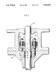
- FIG. 2 is a sectional view of another embodiment of the invention illustrating a packing containment with a zero clearance male adapter anti-extrusion ring;
- FIG. 3 is a sectional view of another embodiment illustrating a double packing containment assembly in a live loaded packing condition
- FIG. 4 is a perspective view illustrating a preferred embodiment of a flat, scarf cut, zero clearance anti-extrusion ring according to the invention
- FIG. 5 is a perspective view of another embodiment of a scarf cut, zero clearance anti-extrusion ring having a wedge face upper surface
- FIG. 6 is a perspective view of another embodiment of the invention illustrating a step cut, zero clearance anti-extrusion ring
- FIG. 7 is a perspective view illustrating another zero clearance anti-extrusion ring incorporating a fracture in accordance with another embodiment of the invention.
- FIG. 8 is a perspective view of still another embodiment of a zero clearance anti-extrusion ring comprising a scarf cut, male adapter ring for PTFE packing.
- FIGS. 1 and 2 illustrate zero clearance anti-extrusion rings for containment of PTFE packing in a single packing configuration in accordance with one aspect of the present invention.
- FIG. 3 illustrates zero clearance anti-extrusion rings for containment of PTFE packing in a double packing configuration in accordance with another aspect of the present invention.
- FIG. 3 illustrates a live loaded packing structure. It is to be understood that the packing configurations shown in FIGS. 1 and 2 are also subjected to either a live loaded condition or a conventional static loaded system.
- each of the packing containment illustrations of FIGS. 1-3 in accordance with the principles of the present invention can handle PTFE packing stresses under continually loaded conditions to a stress level of 2,000 to 4,000 psi (13790-27580 kPa). Under such high stress levels, PTFE packing would normally cold flow and extrude out of the sealing area of conventional packing box designs.
- the reliable sealing feature of the present invention is especially important where toxic fluids are being handled by a fluid valve or a pump and in other similar strict fluid leakage requirements.
- a packing 16 surrounds valve stem 12 and is formed of a series of rings of the type commonly referred to as V-type packing. As shown in FIG. 1, there are five V-rings in packing 16, including a top female ring 16a; three identical middle rings 16b; and a bottom male ring 16c.
- V-type packing 16 is formed of PTFE (polytetrafluorethylene - a synthetic resin polymer) and therefore packing 16 is known in the trade as "V-type PTFE packing".
- Packing suitably formed of other material, or of other synthetic resin polymers having properties similar to PTFE, i.e., low elasticity, low frictional coefficient and good lubricating characteristics, may be utilized. However, the present invention is particularly useful where PTFE packing is desired because of its inertness and low friction characteristics.
- PTFE packing 16 is maintained under suitable loading in the packing bore by means of a packing follower 15 at one end and a packing box ring 17 at the other end.
- each zero clearance anti-extrusion ring 18 is formed of a high strength polymer material with an inner diameter slightly less than the outer diameter of shaft 12.
- Each ring 18 is also split with an angled scarf cut to enable radial interference with shaft 12 while enabling the ring to be readily assembled on shaft 12.
- the outer diameter of zero clearance anti-extrusion rings 18 is slightly smaller than the packing bore within valve housing 14.
- a zero clearance anti-extrusion ring 18 in accordance with the present invention assures there is always zero clearance or an interference fit between the outside diameter of shaft 12 and the ring inside diameter to prevent extrusion of the PTFE packing material while still enabling the anti-extrusion rings to move axially along the shaft.
- the ability of the anti-extrusion rings to move freely along the shaft is necessary for the following reasons:
- rings 18 are not contained volumetrically and therefore only the linear expansion of the ring material needs to be considered when determining the spring travel required in a live load packing system.
- rings 18 be formed of a polymer material having a higher strength than PTFE with less deformation under load than PTFE and with a material that is compatible in wear characteristics with shaft 12. It is preferred to use anti-extrusion rings 18 formed of a high compressive strength linear polymer such as polyetheretherketone (PEEK). Other materials to form rings 18 may also be used such as a properly formed carbon ring or even a metal ring if the metal has compatible wear characteristics with the shaft.
- PEEK polyetheretherketone
- FIG. 4 illustrates a flat, scarf cut, zero clearance anti-extrusion ring 18 in accordance with the principles of the present invention.
- Upper surface 20 and opposite surface 22 are parallel to each other.
- Ring 18 is split by means of a scarf cut 24 caused by a cutting tool placed at an angle to the plane of ring 18 to form an overlapping joint.
- Cut line 26 at top surface 20 is laterally displaced from cut line 28 on bottom surface 22.
- inner surface 30 of ring 18 is machined so that the ring inner diameter is slightly less than the outer diameter of shaft 12.
- Scarf cut 24 permits ready assembly of ring 18 onto shaft 12 such that there will be a zero clearance, interference fit between the shaft outer diameter and the ring inner diameter.
- ring outer surface 32 is machined to have an outer diameter slightly less than the packing bore diameter within valve housing 14.
- FIG. 5 illustrates another embodiment of a zero clearance anti-extrusion ring 34 similar in all respects to ring 18 shown in FIG. 4 except that surface 36 is wedge shaped in that inner ring surface 38 is thicker than outer surface 40. Wedge shaped surface 36 may aid in enabling PTFE packing 16 to provide additional loading of the anti-extrusion ring against the shaft.
- FIG. 6 illustrates still another embodiment of a zero clearance anti-extrusion ring 42 in accordance with the present invention.
- Ring 42 is similar in all respects to ring 18 shown in FIG. 4 except that ring 42 is split by means of a step cut 44 instead of an angled scarf cut to form an overlapping joint.
- Step cut 44 may be provided so that cut 46 on one surface is laterally displaced from cut 48 on the opposite ring surface.
- rings 18, 34 and 42 be formed of a high compressive strength linear polymer such as PEEK.
- a zero clearance anti-extrusion ring in accordance with the present invention may also be provided by a carbon ring 50 which is scored and split by means of a fracture 52 to form a non-overlapping butt joint.
- Ring 50 has an inner surface 54 formed with an inner diameter slightly less than the diameter of shaft 12 and an outer surface 56 with a diameter slightly less than the packing bore in valve housing 14 similar to the construction of rings 18, 34 and 42.
- fracture 52 enables carbon ring 50 to be inserted onto an operating member with a zero clearance or interference fit with the operating member while still permitting axial movement on the operating member and thereby transmitting gland loading to the packing.
- FIG. 2 illustrates another single packing configuration utilizing zero clearance anti-extrusion wiper rings in a packing containment 58 for a valve shaft 60 within a valve housing 62.
- Packing containment 58 includes V-type packing rings 16 bounded by a zero clearance anti-extrusion wiper ring 18 and a zero clearance anti-extrusion ring 64.
- PTFE packing 16 includes a top female ring 16a and three identical middle rings 16b.
- the normal male PTFE ring 16c (FIG. 1) is replaced by a zero clearance anti-extrusion ring 64 formed in accordance with the principles of the present invention as described with respect to rings 18 but having the shape of a normal male bottom ring such as ring 16c shown in FIG. 1.
- FIG. 8 wherein there is shown a zero clearance anti-extrusion ring in the form of male adapter ring 64 split in two by means of a scarf cut 66 such that cut 68 on one ring surface is circumferentially displaced from cut 70 on an opposite ring surface.
- Inner surface 72 and outer surface 74 are dimensioned in accordance with the invention as previously described in connection with surfaces 30 and 32 of ring 18.
- male adapter ring 64 is formed of PEEK material.
- Anti-extrusion ring 64 having the shape of a male adapter in a normal PTFE packing configuration allows the number of PTFE rings in the packing configuration to be reduced. This is desirable because the thermal expansion of PTFE packing material is about 10 times that of the metal packing box and volumetric expansion of the PTFE packing must be considered in determining the amount of spring travel required to maintain adequate load on the packing after it has been through a thermal cycle.
- FIG. 2 illustration with packing ring 64 shows four PTFE packing rings (i.e., upper female ring 16a and three identical middle PTFE rings 16b) it is understood that if desired, less than the illustrated four PTFE rings can be utilized with zero clearance anti-extrusion ring 64. This is particularly important and useful in a double packing configuration operating in high temperature conditions.
- Packing configuration 76 for sealing an operating member such as a rotary shaft 78 in a housing such as valve housing 80.
- Packing configuration 76 includes an upper packing 82 and a lower packing 84 separated by a lantern ring 86.
- Packing 82 and 84 are identical and each includes an upper female PTFE V-type packing ring 88. Both packing 82 and 84 are bounded by a zero clearance anti-extrusion ring 18 on one side and a zero clearance anti-extrusion ring 64 on the other side of the packing.
- Packing configuration 76 in accordance with the present invention significantly reduces the number of PTFE packing rings and therefore reduces the amount of PTFE required to maintain a reliable seal of shaft 78.
- live loading of the packing is provided by means of a series of Belleville springs 90 each mounted around a packing stud 92 which in turn is mounted into valve housing 80.
- Initial adjustment of the loading on packing 82 and 84 is provided by means of adjusting packing nuts 94 on studs 92 to apply loading directly onto packing follower 15.
Abstract
Description
Claims (13)
Priority Applications (12)
| Application Number | Priority Date | Filing Date | Title |
|---|---|---|---|
| US07/596,225 US5131666A (en) | 1990-10-12 | 1990-10-12 | Zero clearance anti-extrusion rings for containment of ptfe packing |
| AT91870158T ATE135093T1 (en) | 1990-10-12 | 1991-10-09 | PLAY-FREE SUPPORT RINGS FOR LIMITING PTFE PACKINGS |
| DE69117655T DE69117655T2 (en) | 1990-10-12 | 1991-10-09 | Backlash-free support rings for the restriction of PTFE packings |
| EP91870158A EP0483097B1 (en) | 1990-10-12 | 1991-10-09 | Zero clearance anti-extrusion rings for containment of PTFE packing |
| KR1019910017859A KR920008393A (en) | 1990-10-12 | 1991-10-11 | Seamless protruding ring to accommodate PTFE packing |
| JP3263764A JPH04258574A (en) | 1990-10-12 | 1991-10-11 | Package assembly |
| FI914804A FI100129B (en) | 1990-10-12 | 1991-10-11 | Sealing containment assembly and fluid valve |
| MX9101563A MX9101563A (en) | 1990-10-12 | 1991-10-11 | ZERO SPACE ANTI-EXTRUSION RINGS FOR PTFE PACKING RETAINER |
| ZA918138A ZA918138B (en) | 1990-10-12 | 1991-10-11 | Zero clearance anti-extrusion rings for containment of ptfe packing |
| AU85762/91A AU649724B2 (en) | 1990-10-12 | 1991-10-11 | Zero clearance anti-extrusion rings for containment of PTFE packing |
| CA002053355A CA2053355C (en) | 1990-10-12 | 1991-10-11 | Zero clearance anti-extrusion rings for containment of ptfe packing |
| JP2000006926U JP2607779Y2 (en) | 1990-10-12 | 2000-09-26 | Packing containing assembly |
Applications Claiming Priority (1)
| Application Number | Priority Date | Filing Date | Title |
|---|---|---|---|
| US07/596,225 US5131666A (en) | 1990-10-12 | 1990-10-12 | Zero clearance anti-extrusion rings for containment of ptfe packing |
Publications (1)
| Publication Number | Publication Date |
|---|---|
| US5131666A true US5131666A (en) | 1992-07-21 |
Family
ID=24386480
Family Applications (1)
| Application Number | Title | Priority Date | Filing Date |
|---|---|---|---|
| US07/596,225 Expired - Lifetime US5131666A (en) | 1990-10-12 | 1990-10-12 | Zero clearance anti-extrusion rings for containment of ptfe packing |
Country Status (11)
| Country | Link |
|---|---|
| US (1) | US5131666A (en) |
| EP (1) | EP0483097B1 (en) |
| JP (2) | JPH04258574A (en) |
| KR (1) | KR920008393A (en) |
| AT (1) | ATE135093T1 (en) |
| AU (1) | AU649724B2 (en) |
| CA (1) | CA2053355C (en) |
| DE (1) | DE69117655T2 (en) |
| FI (1) | FI100129B (en) |
| MX (1) | MX9101563A (en) |
| ZA (1) | ZA918138B (en) |
Cited By (53)
| Publication number | Priority date | Publication date | Assignee | Title |
|---|---|---|---|---|
| US5309993A (en) * | 1990-08-27 | 1994-05-10 | Baker Hughes Incorporated | Chevron seal for a well tool |
| US5326074A (en) * | 1992-11-06 | 1994-07-05 | Xomox Corporation | Enhanced sealing arrangement for a rotary valve shaft |
| US5503406A (en) * | 1993-11-26 | 1996-04-02 | Neles-Jamesbury | Assembly for live loading or valve packings |
| US5549276A (en) * | 1991-01-24 | 1996-08-27 | E. I. Du Pont De Nemours And Company | Valve with perfluoroelastomer packing |
| US5577709A (en) * | 1995-10-17 | 1996-11-26 | Henry Valve Company | Stem seal configuration for ball valves |
| US5593166A (en) * | 1994-03-02 | 1997-01-14 | Fisher Controls International, Inc. | Low friction packing |
| US5791629A (en) * | 1996-10-31 | 1998-08-11 | Fisher Controls International, Inc. | Bushing-less stem guided control valve |
| US5865443A (en) * | 1995-08-04 | 1999-02-02 | Nok Corporation | Seal ring |
| US6098723A (en) * | 1997-09-08 | 2000-08-08 | Chicago Pneumatic Tool Company | Reciprocating tool having a piston retainer |
| US6302405B1 (en) | 1999-06-24 | 2001-10-16 | Schlumberger Technology Corporation | Anti-extrusion seal |
| US20030214100A1 (en) * | 2002-05-03 | 2003-11-20 | Pippert Frederick B. | Packing seal assembly for use with reciprocating cylindrical bodies |
| US20040145120A1 (en) * | 2003-01-23 | 2004-07-29 | Faas Wayne R. | Valve plug seal assembly |
| US6832671B1 (en) * | 2001-08-10 | 2004-12-21 | Sonnax Industries, Inc. | Torque converter clutch apply valve |
| US20050205824A1 (en) * | 2004-03-18 | 2005-09-22 | Osborne Charles A | Segmented ball control valve with universal end connections |
| US7100753B1 (en) * | 2003-07-25 | 2006-09-05 | Sonnax Industries, Inc. | Torque converter clutch apply valve |
| US20060232019A1 (en) * | 2005-04-19 | 2006-10-19 | Garrison Hubert F | Encapsulated back-up system for use with seal system |
| US20070200299A1 (en) * | 2006-02-17 | 2007-08-30 | Innicor Subsurface Technologies Inc | Spring/seal element |
| US20080047616A1 (en) * | 2006-08-25 | 2008-02-28 | Fisher Controls International Llc | Low Friction Live-Loaded Packing |
| US20080272555A1 (en) * | 2007-05-03 | 2008-11-06 | Taylor James E | Dynamic seal assembly |
| US20090289423A1 (en) * | 2006-07-12 | 2009-11-26 | Yasunori Sugita | Shaft seal packing and shaft seal structure for valve |
| US20100052259A1 (en) * | 2008-08-29 | 2010-03-04 | Honeywell International Inc. | Scarf cut backup rings |
| WO2012121745A2 (en) | 2011-03-04 | 2012-09-13 | Parker-Hannifin Corporation | Metal chevron axial seal |
| US20120326395A1 (en) * | 2011-06-21 | 2012-12-27 | Mccarthy Lisa | V-pack seal and method for sealing a shaft |
| WO2013049288A1 (en) | 2011-09-27 | 2013-04-04 | Markel Corporation | A self sealing membrane contactor with ptfe tubular membranes |
| CN103620281A (en) * | 2010-07-30 | 2014-03-05 | 世伟洛克公司 | Anti-extrusion packing support |
| US20140084199A1 (en) * | 2011-05-09 | 2014-03-27 | Aker Subsea As | Valve stem seal arrangement |
| WO2013028493A3 (en) * | 2011-08-22 | 2014-05-22 | Victaulic Company | Expansion joint |
| US20150167862A1 (en) * | 2011-09-06 | 2015-06-18 | Parker Hannifin Manufacturing Limited | Low emission valve assembly |
| US20160123468A1 (en) * | 2014-10-30 | 2016-05-05 | Cathedral Energy Services Ltd. | Seal for an oil sealed bearing assembly |
| US9377056B2 (en) | 2014-09-30 | 2016-06-28 | Cathedral Energy Services Ltd. | Bearing stack for a down-hole drilling motor |
| US9593775B2 (en) * | 2015-07-15 | 2017-03-14 | Siemens Energy, Inc. | Radial lead seal assembly for a generator and a radial lead seal assembly of a generator |
| US9627938B2 (en) * | 2015-07-15 | 2017-04-18 | Siemens Energy, Inc. | Radial lead seal assembly for a generator and method incorporating the same |
| US9995394B2 (en) | 2012-01-18 | 2018-06-12 | Halliburton Energy Services, Inc. | Seal ring backup devices and methods for preventing extrusion |
| US20190024486A1 (en) * | 2017-07-20 | 2019-01-24 | Baker Hughes, A Ge Company, Llc | Skive Cut Borehole Screen End Ring |
| US20190085978A1 (en) * | 2017-09-20 | 2019-03-21 | Gardner Denver Petroleum Pumps Llc | Packing for a well service pump |
| US20190170254A1 (en) * | 2017-11-30 | 2019-06-06 | Saint-Gobain Performance Plastics Corporation | Seal, assembly, and methods of using the same |
| US10358895B2 (en) | 2014-12-30 | 2019-07-23 | Halliburton Energy Services, Inc. | Reusable pre-energized backup ring |
| US10520086B2 (en) | 2017-07-11 | 2019-12-31 | T-Lon Products, Inc. | Apparatus and systems for preventing extrusion |
| USD895777S1 (en) | 2017-09-20 | 2020-09-08 | Gardner Denver Petroleum Pumps Llc | Header ring |
| US11248711B2 (en) | 2017-07-31 | 2022-02-15 | Xomox International GmbH & Co. OHG | Shut-off device comprising a sealing device |
| US11353117B1 (en) | 2020-01-17 | 2022-06-07 | Vulcan Industrial Holdings, LLC | Valve seat insert system and method |
| US11384756B1 (en) | 2020-08-19 | 2022-07-12 | Vulcan Industrial Holdings, LLC | Composite valve seat system and method |
| US11391374B1 (en) | 2021-01-14 | 2022-07-19 | Vulcan Industrial Holdings, LLC | Dual ring stuffing box |
| US11421679B1 (en) | 2020-06-30 | 2022-08-23 | Vulcan Industrial Holdings, LLC | Packing assembly with threaded sleeve for interaction with an installation tool |
| US11421680B1 (en) | 2020-06-30 | 2022-08-23 | Vulcan Industrial Holdings, LLC | Packing bore wear sleeve retainer system |
| US11434900B1 (en) | 2022-04-25 | 2022-09-06 | Vulcan Industrial Holdings, LLC | Spring controlling valve |
| USD980876S1 (en) | 2020-08-21 | 2023-03-14 | Vulcan Industrial Holdings, LLC | Fluid end for a pumping system |
| US11613969B2 (en) | 2017-07-20 | 2023-03-28 | Baker Hughes Holdings Llc | Skive cut borehole screen end ring method of use |
| USD986928S1 (en) | 2020-08-21 | 2023-05-23 | Vulcan Industrial Holdings, LLC | Fluid end for a pumping system |
| US11692631B2 (en) | 2020-08-21 | 2023-07-04 | Saint-Gobain Performance Plastics Corporation | Automatic wiper for seal stack assembly |
| USD997992S1 (en) | 2020-08-21 | 2023-09-05 | Vulcan Industrial Holdings, LLC | Fluid end for a pumping system |
| US11761540B2 (en) | 2020-08-19 | 2023-09-19 | Saint-Gobain Performance Plastics Corporation | Seal stack assembly |
| US11920684B1 (en) | 2022-05-17 | 2024-03-05 | Vulcan Industrial Holdings, LLC | Mechanically or hybrid mounted valve seat |
Families Citing this family (11)
| Publication number | Priority date | Publication date | Assignee | Title |
|---|---|---|---|---|
| US5056757A (en) * | 1990-10-12 | 1991-10-15 | Fisher Controls International, Inc. | Packing containment for live loaded fugitive emission seals |
| DE10315896A1 (en) * | 2003-04-08 | 2004-10-28 | Hydac Accessories Gmbh | ball valve |
| JP4875330B2 (en) * | 2005-09-12 | 2012-02-15 | 株式会社フジキン | Gland packing and sealing device using the same |
| JP4649345B2 (en) * | 2006-02-22 | 2011-03-09 | 岡野バルブ製造株式会社 | Spacer ring for shaft seal device |
| JP5292902B2 (en) * | 2008-04-15 | 2013-09-18 | Nok株式会社 | How to install the seal ring |
| KR101171571B1 (en) * | 2010-08-09 | 2012-08-06 | 한국수력원자력 주식회사 | Device and method for installation and removal of valve packing |
| CN105080942A (en) * | 2015-09-28 | 2015-11-25 | 四川制动科技股份有限公司 | Method for recycling scrapped valve body with poor body-sleeve fit |
| JP2017172755A (en) * | 2016-03-25 | 2017-09-28 | 共栄バルブ工業株式会社 | Spherical valve |
| CN106523785A (en) * | 2016-11-25 | 2017-03-22 | 南通龙源电站阀门有限公司 | V-shaped structure valve rod sealing padding |
| JP7142348B2 (en) * | 2017-09-07 | 2022-09-27 | 株式会社ミヤワキ | valve device |
| JP7428875B2 (en) * | 2019-12-13 | 2024-02-07 | 横浜ゴム株式会社 | Tire vulcanization equipment and method |
Citations (30)
| Publication number | Priority date | Publication date | Assignee | Title |
|---|---|---|---|---|
| US687489A (en) * | 1901-09-12 | 1901-11-26 | Karl Reichenbach | Packing for stuffing-boxes. |
| US2815973A (en) * | 1955-07-05 | 1957-12-10 | Chicksan Company | Dynamic seal |
| US3239191A (en) * | 1962-08-03 | 1966-03-08 | Ladish Co | Art of manufacturing ball valves |
| US3421769A (en) * | 1964-08-27 | 1969-01-14 | Commercial Shearing | Shaft seals |
| US3787060A (en) * | 1971-11-12 | 1974-01-22 | Canadian Patents Dev | Valve stem packing assembly |
| US3789879A (en) * | 1972-04-20 | 1974-02-05 | Koppers Co Inc | Self-adjusting sealing apparatus |
| US3916943A (en) * | 1973-08-27 | 1975-11-04 | John L Dore & 0 Co | Plastic lined plug valve |
| US4032159A (en) * | 1975-10-28 | 1977-06-28 | Poly Seal, Inc. | Interference compression seal |
| GB2009338A (en) * | 1977-12-01 | 1979-06-13 | Chesterton A W Co | Elastomeric sealing ring |
| US4234197A (en) * | 1979-01-19 | 1980-11-18 | Baker International Corporation | Conduit sealing system |
| US4380342A (en) * | 1980-09-22 | 1983-04-19 | Vought Corporation | Fluid sealing devices |
| US4406469A (en) * | 1981-09-21 | 1983-09-27 | Baker International Corporation | Plastically deformable conduit seal for subterranean wells |
| US4428590A (en) * | 1981-11-19 | 1984-01-31 | Utex Industries, Inc. | Anti-extrusion sealing device with hinge-like bridge section |
| US4433847A (en) * | 1982-03-25 | 1984-02-28 | Baker Oil Tools, Inc. | Conduit sealing system |
| US4451047A (en) * | 1981-07-31 | 1984-05-29 | Smith International, Inc. | Seal |
| US4516752A (en) * | 1984-01-12 | 1985-05-14 | Joy Manufacturing Company | Mechanically preloaded packing assembly |
| US4558874A (en) * | 1983-07-05 | 1985-12-17 | Whitey Co. | Valve stem packing assembly |
| US4576385A (en) * | 1984-12-12 | 1986-03-18 | Fmc Corporation | Fluid packing assembly with alternating diverse seal ring elements |
| US4618154A (en) * | 1985-07-31 | 1986-10-21 | Freudenthal Merton L | Annular lip type sealing ring with pre-loaded lip portions |
| US4741509A (en) * | 1987-02-19 | 1988-05-03 | Cameron Iron Works, Inc. | Gate valve with improved secondary body to bushing seals |
| GB2202283A (en) * | 1987-03-11 | 1988-09-21 | Arrow Oil Tools Inc | Seals |
| US4807890A (en) * | 1985-10-15 | 1989-02-28 | Esco Elevators, Inc. | Sealing combination |
| US4809992A (en) * | 1987-11-23 | 1989-03-07 | Woodex Bearing Company, Inc. | Rotary shaft seal assembly |
| US4826181A (en) * | 1988-02-09 | 1989-05-02 | Union Carbide Corporation | Seal utilizing composites of flexible graphite particles and amorphous carbon |
| US4840379A (en) * | 1988-06-29 | 1989-06-20 | Greene, Tweed & Co. | Split sealing ring having a bias cut |
| US4844487A (en) * | 1988-11-04 | 1989-07-04 | Kaydon Corporation | Lock-step duo step split sealing ring |
| US4867197A (en) * | 1989-02-15 | 1989-09-19 | Fetterolf Corporation | High pressure valve |
| US4879338A (en) * | 1985-02-13 | 1989-11-07 | Raychem Corporation | Poly(aryl ether ketone) compositions |
| US4886241A (en) * | 1987-09-16 | 1989-12-12 | Fisher Controls International, Inc. | Valve stem packing containment for high pressure, high temperature |
| US4991495A (en) * | 1988-10-11 | 1991-02-12 | Loegel Sr Charles | Pump-actuating mechanism |
Family Cites Families (1)
| Publication number | Priority date | Publication date | Assignee | Title |
|---|---|---|---|---|
| US4527806A (en) * | 1984-12-12 | 1985-07-09 | Fmc Corporation | Valve stem packing |
-
1990
- 1990-10-12 US US07/596,225 patent/US5131666A/en not_active Expired - Lifetime
-
1991
- 1991-10-09 DE DE69117655T patent/DE69117655T2/en not_active Expired - Lifetime
- 1991-10-09 EP EP91870158A patent/EP0483097B1/en not_active Expired - Lifetime
- 1991-10-09 AT AT91870158T patent/ATE135093T1/en not_active IP Right Cessation
- 1991-10-11 MX MX9101563A patent/MX9101563A/en not_active IP Right Cessation
- 1991-10-11 KR KR1019910017859A patent/KR920008393A/en not_active Application Discontinuation
- 1991-10-11 JP JP3263764A patent/JPH04258574A/en active Pending
- 1991-10-11 AU AU85762/91A patent/AU649724B2/en not_active Ceased
- 1991-10-11 ZA ZA918138A patent/ZA918138B/en unknown
- 1991-10-11 CA CA002053355A patent/CA2053355C/en not_active Expired - Lifetime
- 1991-10-11 FI FI914804A patent/FI100129B/en not_active IP Right Cessation
-
2000
- 2000-09-26 JP JP2000006926U patent/JP2607779Y2/en not_active Expired - Fee Related
Patent Citations (30)
| Publication number | Priority date | Publication date | Assignee | Title |
|---|---|---|---|---|
| US687489A (en) * | 1901-09-12 | 1901-11-26 | Karl Reichenbach | Packing for stuffing-boxes. |
| US2815973A (en) * | 1955-07-05 | 1957-12-10 | Chicksan Company | Dynamic seal |
| US3239191A (en) * | 1962-08-03 | 1966-03-08 | Ladish Co | Art of manufacturing ball valves |
| US3421769A (en) * | 1964-08-27 | 1969-01-14 | Commercial Shearing | Shaft seals |
| US3787060A (en) * | 1971-11-12 | 1974-01-22 | Canadian Patents Dev | Valve stem packing assembly |
| US3789879A (en) * | 1972-04-20 | 1974-02-05 | Koppers Co Inc | Self-adjusting sealing apparatus |
| US3916943A (en) * | 1973-08-27 | 1975-11-04 | John L Dore & 0 Co | Plastic lined plug valve |
| US4032159A (en) * | 1975-10-28 | 1977-06-28 | Poly Seal, Inc. | Interference compression seal |
| GB2009338A (en) * | 1977-12-01 | 1979-06-13 | Chesterton A W Co | Elastomeric sealing ring |
| US4234197A (en) * | 1979-01-19 | 1980-11-18 | Baker International Corporation | Conduit sealing system |
| US4380342A (en) * | 1980-09-22 | 1983-04-19 | Vought Corporation | Fluid sealing devices |
| US4451047A (en) * | 1981-07-31 | 1984-05-29 | Smith International, Inc. | Seal |
| US4406469A (en) * | 1981-09-21 | 1983-09-27 | Baker International Corporation | Plastically deformable conduit seal for subterranean wells |
| US4428590A (en) * | 1981-11-19 | 1984-01-31 | Utex Industries, Inc. | Anti-extrusion sealing device with hinge-like bridge section |
| US4433847A (en) * | 1982-03-25 | 1984-02-28 | Baker Oil Tools, Inc. | Conduit sealing system |
| US4558874A (en) * | 1983-07-05 | 1985-12-17 | Whitey Co. | Valve stem packing assembly |
| US4516752A (en) * | 1984-01-12 | 1985-05-14 | Joy Manufacturing Company | Mechanically preloaded packing assembly |
| US4576385A (en) * | 1984-12-12 | 1986-03-18 | Fmc Corporation | Fluid packing assembly with alternating diverse seal ring elements |
| US4879338A (en) * | 1985-02-13 | 1989-11-07 | Raychem Corporation | Poly(aryl ether ketone) compositions |
| US4618154A (en) * | 1985-07-31 | 1986-10-21 | Freudenthal Merton L | Annular lip type sealing ring with pre-loaded lip portions |
| US4807890A (en) * | 1985-10-15 | 1989-02-28 | Esco Elevators, Inc. | Sealing combination |
| US4741509A (en) * | 1987-02-19 | 1988-05-03 | Cameron Iron Works, Inc. | Gate valve with improved secondary body to bushing seals |
| GB2202283A (en) * | 1987-03-11 | 1988-09-21 | Arrow Oil Tools Inc | Seals |
| US4886241A (en) * | 1987-09-16 | 1989-12-12 | Fisher Controls International, Inc. | Valve stem packing containment for high pressure, high temperature |
| US4809992A (en) * | 1987-11-23 | 1989-03-07 | Woodex Bearing Company, Inc. | Rotary shaft seal assembly |
| US4826181A (en) * | 1988-02-09 | 1989-05-02 | Union Carbide Corporation | Seal utilizing composites of flexible graphite particles and amorphous carbon |
| US4840379A (en) * | 1988-06-29 | 1989-06-20 | Greene, Tweed & Co. | Split sealing ring having a bias cut |
| US4991495A (en) * | 1988-10-11 | 1991-02-12 | Loegel Sr Charles | Pump-actuating mechanism |
| US4844487A (en) * | 1988-11-04 | 1989-07-04 | Kaydon Corporation | Lock-step duo step split sealing ring |
| US4867197A (en) * | 1989-02-15 | 1989-09-19 | Fetterolf Corporation | High pressure valve |
Non-Patent Citations (5)
| Title |
|---|
| Encyclopedia of Polymer Science and Engineering, vol. 6, pp.103 104, John Wiley & Sons, New York, 1986. * |
| Encyclopedia of Polymer Science and Engineering, vol. 6, pp.103-104, John Wiley & Sons, New York, 1986. |
| Handbook of Mechanical Packings and Gasket Materials, Mechanical Packing Assoc., New York, 1960. * |
| Precision Rubber Products Corporation, Design Manual, "Gland Design", pp. 8-10. |
| Precision Rubber Products Corporation, Design Manual, Gland Design , pp. 8 10. * |
Cited By (77)
| Publication number | Priority date | Publication date | Assignee | Title |
|---|---|---|---|---|
| US5309993A (en) * | 1990-08-27 | 1994-05-10 | Baker Hughes Incorporated | Chevron seal for a well tool |
| US5549276A (en) * | 1991-01-24 | 1996-08-27 | E. I. Du Pont De Nemours And Company | Valve with perfluoroelastomer packing |
| US5788216A (en) * | 1991-01-24 | 1998-08-04 | E. I. Du Pont De Nemours And Company | Valve with perfluoroelastomer packing |
| US5326074A (en) * | 1992-11-06 | 1994-07-05 | Xomox Corporation | Enhanced sealing arrangement for a rotary valve shaft |
| US5503406A (en) * | 1993-11-26 | 1996-04-02 | Neles-Jamesbury | Assembly for live loading or valve packings |
| US5593166A (en) * | 1994-03-02 | 1997-01-14 | Fisher Controls International, Inc. | Low friction packing |
| US5865443A (en) * | 1995-08-04 | 1999-02-02 | Nok Corporation | Seal ring |
| US6468068B1 (en) * | 1995-08-04 | 2002-10-22 | Nok Corporation | Resin seal ring die with various mold cut portions |
| US5577709A (en) * | 1995-10-17 | 1996-11-26 | Henry Valve Company | Stem seal configuration for ball valves |
| US5791629A (en) * | 1996-10-31 | 1998-08-11 | Fisher Controls International, Inc. | Bushing-less stem guided control valve |
| US6098723A (en) * | 1997-09-08 | 2000-08-08 | Chicago Pneumatic Tool Company | Reciprocating tool having a piston retainer |
| US6302405B1 (en) | 1999-06-24 | 2001-10-16 | Schlumberger Technology Corporation | Anti-extrusion seal |
| US6832671B1 (en) * | 2001-08-10 | 2004-12-21 | Sonnax Industries, Inc. | Torque converter clutch apply valve |
| US20030214100A1 (en) * | 2002-05-03 | 2003-11-20 | Pippert Frederick B. | Packing seal assembly for use with reciprocating cylindrical bodies |
| US20040145120A1 (en) * | 2003-01-23 | 2004-07-29 | Faas Wayne R. | Valve plug seal assembly |
| US6840520B2 (en) * | 2003-01-23 | 2005-01-11 | Fisher Controls International Llc | Valve plug seal assembly |
| US7100753B1 (en) * | 2003-07-25 | 2006-09-05 | Sonnax Industries, Inc. | Torque converter clutch apply valve |
| US20050205824A1 (en) * | 2004-03-18 | 2005-09-22 | Osborne Charles A | Segmented ball control valve with universal end connections |
| US20060232019A1 (en) * | 2005-04-19 | 2006-10-19 | Garrison Hubert F | Encapsulated back-up system for use with seal system |
| US20070290454A1 (en) * | 2005-04-19 | 2007-12-20 | Bj Services Company | Encapsulated back-up system for use with seal system |
| US20070200299A1 (en) * | 2006-02-17 | 2007-08-30 | Innicor Subsurface Technologies Inc | Spring/seal element |
| US20090289423A1 (en) * | 2006-07-12 | 2009-11-26 | Yasunori Sugita | Shaft seal packing and shaft seal structure for valve |
| US8132785B2 (en) * | 2006-07-12 | 2012-03-13 | Kitz Corporation | Shaft seal packing and shaft seal structure for valve |
| US20080047616A1 (en) * | 2006-08-25 | 2008-02-28 | Fisher Controls International Llc | Low Friction Live-Loaded Packing |
| US8622367B2 (en) | 2006-08-25 | 2014-01-07 | Fisher Controls International Llc | Low friction live-loaded packing |
| US7963502B2 (en) * | 2006-08-25 | 2011-06-21 | Fisher Controls International Llc | Low friction live-loaded packing |
| US20110209777A1 (en) * | 2006-08-25 | 2011-09-01 | Fisher Controls International Llc | Low friction live-loaded packing |
| US20080272555A1 (en) * | 2007-05-03 | 2008-11-06 | Taylor James E | Dynamic seal assembly |
| US7717433B2 (en) * | 2007-05-03 | 2010-05-18 | Equistar Chemicals, Lp | Dynamic seal assembly |
| US8262091B2 (en) | 2008-08-29 | 2012-09-11 | Honeywell International Inc. | Scarf cut backup rings |
| US20100052259A1 (en) * | 2008-08-29 | 2010-03-04 | Honeywell International Inc. | Scarf cut backup rings |
| CN103620281B (en) * | 2010-07-30 | 2015-11-25 | 世伟洛克公司 | Anti-extrusion filling bearing device |
| CN103620281A (en) * | 2010-07-30 | 2014-03-05 | 世伟洛克公司 | Anti-extrusion packing support |
| WO2012015716A3 (en) * | 2010-07-30 | 2014-03-27 | Swagelok Company | Anti-extrusion packing support |
| US8814139B2 (en) | 2010-07-30 | 2014-08-26 | Swagelok Company | Anti-extrusion packing support |
| WO2012121745A2 (en) | 2011-03-04 | 2012-09-13 | Parker-Hannifin Corporation | Metal chevron axial seal |
| US9458691B2 (en) | 2011-03-04 | 2016-10-04 | Parker-Hannifin Corporation | Metal chevron axial seal |
| US20140084199A1 (en) * | 2011-05-09 | 2014-03-27 | Aker Subsea As | Valve stem seal arrangement |
| US9194511B2 (en) * | 2011-05-09 | 2015-11-24 | Aker Subsea As | Valve stem seal arrangement |
| US8807572B2 (en) * | 2011-06-21 | 2014-08-19 | Lisa McCarthy | V-pack seal and method for sealing a shaft |
| US20120326395A1 (en) * | 2011-06-21 | 2012-12-27 | Mccarthy Lisa | V-pack seal and method for sealing a shaft |
| US9631759B2 (en) | 2011-08-22 | 2017-04-25 | Victaulic Company | Expansion joint for pipelines |
| WO2013028493A3 (en) * | 2011-08-22 | 2014-05-22 | Victaulic Company | Expansion joint |
| JP2014527144A (en) * | 2011-08-22 | 2014-10-09 | ビクターリック カンパニー | Expansion joints |
| US20150167862A1 (en) * | 2011-09-06 | 2015-06-18 | Parker Hannifin Manufacturing Limited | Low emission valve assembly |
| US9512931B2 (en) * | 2011-09-06 | 2016-12-06 | Parker Hannifin Manufacturing Limited | Low emission valve assembly |
| US9061251B2 (en) | 2011-09-27 | 2015-06-23 | Markel Corporation | Self sealing membrane contactor with PTFE tubular membranes |
| WO2013049288A1 (en) | 2011-09-27 | 2013-04-04 | Markel Corporation | A self sealing membrane contactor with ptfe tubular membranes |
| US9995394B2 (en) | 2012-01-18 | 2018-06-12 | Halliburton Energy Services, Inc. | Seal ring backup devices and methods for preventing extrusion |
| US9377056B2 (en) | 2014-09-30 | 2016-06-28 | Cathedral Energy Services Ltd. | Bearing stack for a down-hole drilling motor |
| US20160123468A1 (en) * | 2014-10-30 | 2016-05-05 | Cathedral Energy Services Ltd. | Seal for an oil sealed bearing assembly |
| US10358895B2 (en) | 2014-12-30 | 2019-07-23 | Halliburton Energy Services, Inc. | Reusable pre-energized backup ring |
| US9627938B2 (en) * | 2015-07-15 | 2017-04-18 | Siemens Energy, Inc. | Radial lead seal assembly for a generator and method incorporating the same |
| US9593775B2 (en) * | 2015-07-15 | 2017-03-14 | Siemens Energy, Inc. | Radial lead seal assembly for a generator and a radial lead seal assembly of a generator |
| US10520086B2 (en) | 2017-07-11 | 2019-12-31 | T-Lon Products, Inc. | Apparatus and systems for preventing extrusion |
| US11613969B2 (en) | 2017-07-20 | 2023-03-28 | Baker Hughes Holdings Llc | Skive cut borehole screen end ring method of use |
| WO2019018678A1 (en) * | 2017-07-20 | 2019-01-24 | Baker Hughes, A Ge Company, Llc | Skive cut borehole screen end ring |
| US20190024486A1 (en) * | 2017-07-20 | 2019-01-24 | Baker Hughes, A Ge Company, Llc | Skive Cut Borehole Screen End Ring |
| GB2579497A (en) * | 2017-07-20 | 2020-06-24 | Baker Hughes A Ge Co Llc | Skive cut borehole screen end ring |
| US11248711B2 (en) | 2017-07-31 | 2022-02-15 | Xomox International GmbH & Co. OHG | Shut-off device comprising a sealing device |
| USD895777S1 (en) | 2017-09-20 | 2020-09-08 | Gardner Denver Petroleum Pumps Llc | Header ring |
| US20190085978A1 (en) * | 2017-09-20 | 2019-03-21 | Gardner Denver Petroleum Pumps Llc | Packing for a well service pump |
| US10837556B2 (en) * | 2017-09-20 | 2020-11-17 | Fardner Denver Petroleum Pumps Llc | Packing for a well service pump |
| US20190170254A1 (en) * | 2017-11-30 | 2019-06-06 | Saint-Gobain Performance Plastics Corporation | Seal, assembly, and methods of using the same |
| US11353117B1 (en) | 2020-01-17 | 2022-06-07 | Vulcan Industrial Holdings, LLC | Valve seat insert system and method |
| US11421679B1 (en) | 2020-06-30 | 2022-08-23 | Vulcan Industrial Holdings, LLC | Packing assembly with threaded sleeve for interaction with an installation tool |
| US11421680B1 (en) | 2020-06-30 | 2022-08-23 | Vulcan Industrial Holdings, LLC | Packing bore wear sleeve retainer system |
| US11384756B1 (en) | 2020-08-19 | 2022-07-12 | Vulcan Industrial Holdings, LLC | Composite valve seat system and method |
| US11761540B2 (en) | 2020-08-19 | 2023-09-19 | Saint-Gobain Performance Plastics Corporation | Seal stack assembly |
| USD997992S1 (en) | 2020-08-21 | 2023-09-05 | Vulcan Industrial Holdings, LLC | Fluid end for a pumping system |
| USD980876S1 (en) | 2020-08-21 | 2023-03-14 | Vulcan Industrial Holdings, LLC | Fluid end for a pumping system |
| USD986928S1 (en) | 2020-08-21 | 2023-05-23 | Vulcan Industrial Holdings, LLC | Fluid end for a pumping system |
| US11692631B2 (en) | 2020-08-21 | 2023-07-04 | Saint-Gobain Performance Plastics Corporation | Automatic wiper for seal stack assembly |
| US11391374B1 (en) | 2021-01-14 | 2022-07-19 | Vulcan Industrial Holdings, LLC | Dual ring stuffing box |
| US11434900B1 (en) | 2022-04-25 | 2022-09-06 | Vulcan Industrial Holdings, LLC | Spring controlling valve |
| US11761441B1 (en) * | 2022-04-25 | 2023-09-19 | Vulcan Industrial Holdings, LLC | Spring controlling valve |
| US11920684B1 (en) | 2022-05-17 | 2024-03-05 | Vulcan Industrial Holdings, LLC | Mechanically or hybrid mounted valve seat |
Also Published As
| Publication number | Publication date |
|---|---|
| EP0483097A1 (en) | 1992-04-29 |
| JP2607779Y2 (en) | 2002-07-08 |
| ATE135093T1 (en) | 1996-03-15 |
| FI914804A (en) | 1992-04-13 |
| AU649724B2 (en) | 1994-06-02 |
| JP2001000017U (en) | 2001-04-27 |
| CA2053355A1 (en) | 1992-04-13 |
| ZA918138B (en) | 1992-08-26 |
| DE69117655T2 (en) | 1996-07-18 |
| CA2053355C (en) | 2003-05-06 |
| AU8576291A (en) | 1992-04-16 |
| DE69117655D1 (en) | 1996-04-11 |
| FI100129B (en) | 1997-09-30 |
| JPH04258574A (en) | 1992-09-14 |
| FI914804A0 (en) | 1991-10-11 |
| MX9101563A (en) | 1992-06-05 |
| KR920008393A (en) | 1992-05-27 |
| EP0483097B1 (en) | 1996-03-06 |
Similar Documents
| Publication | Publication Date | Title |
|---|---|---|
| US5131666A (en) | Zero clearance anti-extrusion rings for containment of ptfe packing | |
| US5056757A (en) | Packing containment for live loaded fugitive emission seals | |
| US4280522A (en) | Fire seal for valves | |
| US6007070A (en) | Pressure actuated packing assembly | |
| US4706970A (en) | Flexible ring seal with insert in circumferentially extending channel | |
| AU679347B2 (en) | Low friction packing | |
| US4451047A (en) | Seal | |
| US4582330A (en) | Seal with cleft seating surface | |
| US4363465A (en) | Extreme temperature, high pressure balanced, rising stem gate valve with super preloaded, stacked, solid lubricated, metal-to-metal seal | |
| CA1239631A (en) | Mechanically preloaded packing assembly | |
| US6726220B2 (en) | Dual seal assembly | |
| US4206930A (en) | Circumferentially compressed piston ring assembly and method | |
| US4936197A (en) | Dynamic seal construction | |
| EP0130841A2 (en) | Valve stem packing assembly | |
| EP0424372B1 (en) | A combination seal for sealing between two machine parts | |
| US6648337B1 (en) | Backup ring with controlled spacing | |
| IE49968B1 (en) | Packing assembly for sealing a movable shaft to a housing | |
| US4109924A (en) | Stepped joint piston ring | |
| US6588763B1 (en) | Seal arrangement providing a seal between a bore and a rod moveable in the bore | |
| US4809993A (en) | Stuffing box sealing device | |
| US4380342A (en) | Fluid sealing devices | |
| US3359048A (en) | Dynamic shaft sealing device and bushing therefor | |
| GB2340899A (en) | Protection of a lip seal | |
| EP0752551B1 (en) | An improved seal arrangement | |
| US4437674A (en) | Fluid sealing devices |
Legal Events
| Date | Code | Title | Description |
|---|---|---|---|
| AS | Assignment |
Owner name: FISHER CONTROLS INTERNATIONAL, INC., A CORP. OF DE Free format text: ASSIGNMENT OF ASSIGNORS INTEREST.;ASSIGNOR:HUTCHENS, WILBUR D.;REEL/FRAME:005520/0044 Effective date: 19901101 |
|
| STCF | Information on status: patent grant |
Free format text: PATENTED CASE |
|
| FEPP | Fee payment procedure |
Free format text: PAYOR NUMBER ASSIGNED (ORIGINAL EVENT CODE: ASPN); ENTITY STATUS OF PATENT OWNER: LARGE ENTITY |
|
| FPAY | Fee payment |
Year of fee payment: 4 |
|
| FPAY | Fee payment |
Year of fee payment: 8 |
|
| AS | Assignment |
Owner name: FISHER CONTROLS INTERNATIONAL LLC, MISSOURI Free format text: CHANGE OF NAME;ASSIGNOR:FISHER CONTROLS INTERNATIONAL, INC.;REEL/FRAME:013496/0150 Effective date: 20020815 |
|
| FPAY | Fee payment |
Year of fee payment: 12 |