US5133645A - Common rail fuel injection system - Google Patents
Common rail fuel injection system Download PDFInfo
- Publication number
- US5133645A US5133645A US07/553,523 US55352390A US5133645A US 5133645 A US5133645 A US 5133645A US 55352390 A US55352390 A US 55352390A US 5133645 A US5133645 A US 5133645A
- Authority
- US
- United States
- Prior art keywords
- fuel
- plunger
- chamber
- valve
- pump
- Prior art date
- Legal status (The legal status is an assumption and is not a legal conclusion. Google has not performed a legal analysis and makes no representation as to the accuracy of the status listed.)
- Expired - Lifetime
Links
Images


Classifications
-
- F—MECHANICAL ENGINEERING; LIGHTING; HEATING; WEAPONS; BLASTING
- F02—COMBUSTION ENGINES; HOT-GAS OR COMBUSTION-PRODUCT ENGINE PLANTS
- F02M—SUPPLYING COMBUSTION ENGINES IN GENERAL WITH COMBUSTIBLE MIXTURES OR CONSTITUENTS THEREOF
- F02M55/00—Fuel-injection apparatus characterised by their fuel conduits or their venting means; Arrangements of conduits between fuel tank and pump F02M37/00
-
- F—MECHANICAL ENGINEERING; LIGHTING; HEATING; WEAPONS; BLASTING
- F02—COMBUSTION ENGINES; HOT-GAS OR COMBUSTION-PRODUCT ENGINE PLANTS
- F02M—SUPPLYING COMBUSTION ENGINES IN GENERAL WITH COMBUSTIBLE MIXTURES OR CONSTITUENTS THEREOF
- F02M47/00—Fuel-injection apparatus operated cyclically with fuel-injection valves actuated by fluid pressure
- F02M47/02—Fuel-injection apparatus operated cyclically with fuel-injection valves actuated by fluid pressure of accumulator-injector type, i.e. having fuel pressure of accumulator tending to open, and fuel pressure in other chamber tending to close, injection valves and having means for periodically releasing that closing pressure
- F02M47/027—Electrically actuated valves draining the chamber to release the closing pressure
-
- F—MECHANICAL ENGINEERING; LIGHTING; HEATING; WEAPONS; BLASTING
- F02—COMBUSTION ENGINES; HOT-GAS OR COMBUSTION-PRODUCT ENGINE PLANTS
- F02M—SUPPLYING COMBUSTION ENGINES IN GENERAL WITH COMBUSTIBLE MIXTURES OR CONSTITUENTS THEREOF
- F02M59/00—Pumps specially adapted for fuel-injection and not provided for in groups F02M39/00 -F02M57/00, e.g. rotary cylinder-block type of pumps
- F02M59/20—Varying fuel delivery in quantity or timing
- F02M59/36—Varying fuel delivery in quantity or timing by variably-timed valves controlling fuel passages to pumping elements or overflow passages
- F02M59/366—Valves being actuated electrically
- F02M59/367—Pump inlet valves of the check valve type being open when actuated
-
- F—MECHANICAL ENGINEERING; LIGHTING; HEATING; WEAPONS; BLASTING
- F02—COMBUSTION ENGINES; HOT-GAS OR COMBUSTION-PRODUCT ENGINE PLANTS
- F02M—SUPPLYING COMBUSTION ENGINES IN GENERAL WITH COMBUSTIBLE MIXTURES OR CONSTITUENTS THEREOF
- F02M59/00—Pumps specially adapted for fuel-injection and not provided for in groups F02M39/00 -F02M57/00, e.g. rotary cylinder-block type of pumps
- F02M59/44—Details, components parts, or accessories not provided for in, or of interest apart from, the apparatus of groups F02M59/02 - F02M59/42; Pumps having transducers, e.g. to measure displacement of pump rack or piston
-
- F—MECHANICAL ENGINEERING; LIGHTING; HEATING; WEAPONS; BLASTING
- F02—COMBUSTION ENGINES; HOT-GAS OR COMBUSTION-PRODUCT ENGINE PLANTS
- F02M—SUPPLYING COMBUSTION ENGINES IN GENERAL WITH COMBUSTIBLE MIXTURES OR CONSTITUENTS THEREOF
- F02M63/00—Other fuel-injection apparatus having pertinent characteristics not provided for in groups F02M39/00 - F02M57/00 or F02M67/00; Details, component parts, or accessories of fuel-injection apparatus, not provided for in, or of interest apart from, the apparatus of groups F02M39/00 - F02M61/00 or F02M67/00; Combination of fuel pump with other devices, e.g. lubricating oil pump
- F02M63/02—Fuel-injection apparatus having several injectors fed by a common pumping element, or having several pumping elements feeding a common injector; Fuel-injection apparatus having provisions for cutting-out pumps, pumping elements, or injectors; Fuel-injection apparatus having provisions for variably interconnecting pumping elements and injectors alternatively
- F02M63/0225—Fuel-injection apparatus having a common rail feeding several injectors ; Means for varying pressure in common rails; Pumps feeding common rails
Definitions
- This invention relates generally to fuel injection systems for engines and, in particular, diesel engine applications.
- the common rail fuel system consists primarily of a high-pressure fixed displacement fuel pump, nozzles, a rail or rails having relatively constant pressure situated between the fuel pump and the nozzles, the necessary connecting fuel lines, and an electronic control system.
- a fixed displacement pump controls the fuel flow to the engine and increases the pressure and volume of the fuel as required for optimum combustion.
- Injection pressure is controlled by electronically controlled nozzles which determine the duration of injection. Injection pressure can be varied by varying the on time of the nozzle solenoid while the output of the pump is held constant.
- the inlet valve of the high-pressure pump is a metering valve which is actuated by a solenoid.
- the electrical pulse to the solenoid is supplied by the electronic control system, which is also responsible for matching of the metered fuel volume to the fuel volume required for the engine operating conditions.
- the electronic control system determines the beginning and end of the electronic pulse sent to the solenoid stator which actuates the metering inlet valve. System characteristics determine the armature and valve assembly response. Correlation of the duration of the solenoid activation pulse to the fuel requirement of the engine is established by a fuel map developed through test and programmed into the controller.
- the relative constant pressure supply fuel is boosted to injection pressure by the high-pressure fuel pump.
- Fuel volume is metered by the inlet valves.
- the inlet valve is actuated by a solenoid and opens shortly after the plunger begins the retraction stroke. Fuel at supply pressure flows in to fill the cavity produced by the retracting plunger.
- the inlet valve closes. Plunger travel during the time the inlet valve is held open determines the volume displaced by the plunger and, therefore, the volume of fuel admitted to the high-pressure chamber of the pump.
- the pumping chamber As the plunger continues to retract after closing of the inlet valve, a vacuum is created in the pumping chamber. Near the end of the plunger retraction stroke, the leakage return port is uncovered. The vacuum in the pumping chamber increases the pressure differential between the leakage system and the pumping chamber, improving fuel flow from the leakage system into the pumping chamber. Once equilibrium of the leakage system has been achieved, the volume of leakage system fuel which is held in the pumping chamber is equal to the leakage of the plunger and nozzle(s) during one pumping and retraction cycle of the plunger.
- the leakage return port is uncovered.
- a check valve may be placed in the leakage return line to prevent fuel from escaping until the port is closed by the upward moving plunger. Otherwise the pump output will be reduced by the volume of fuel which escaped. Pressure will begin to increase in the pumping chamber as soon as the plunger begins to rise if a check valve is used. If no check valve is placed in the leakage return line to prevent fuel from flowing out of the leakage return port, pressure will begin to increase when the port is closed by the upward moving plunger. The rate of increase is a function of volume of fuel trapped in the pumping chamber and bulk modulus of the fuel.
- the delivery valve opens and fuel flows from the pumping chamber into the rail. Fuel continues to flow from the pumping chamber into the rail until the plunger direction again reverses and the plunger begins to retract, increasing pumping chamber volume and reducing pressure in the pumping chamber. The rail pressure, assisted by the spring load, if present, closes the delivery valve.
- Steady-state rail pressure and pump output are maintained by controlling the relative on duration of the fuel pump inlet solenoid and the nozzle solenoid signal duration, and are controlled by the ECM.
- fuel pump inlet solenoid signal duration is maximized until rail pressure is attained.
- solenoid signal durations are adjusted by the ECM to maintain the desired speed as determined by throttle position.
- Pulses are created by the opening and closing of the injection valve in the nozzle. These pulses can be phased relative to the pulses generated by the pump by advancing or retarding the pump with respect to the nozzle to achieve the most favorable interaction between pump and nozzle pulses. Nozzle event timing is controlled only by combustion factors.
- Rail pressure can be maintained relatively constant, varying only by the fluctuations due to the output pulses of the pump and the injection pulses. These fluctuations are small relative to injection pressure, being attenuated by the elasticity of the reservoir structure and volume of high-pressure fuel. Rail pressure is also independent of speed.
- the common rail system of the invention provides the advantage that fuel at injection pressure is available at the nozzle immediately upon opening of the valve in the tip of the nozzle and the opportunity to maintain a more advantageous spray pattern throughout a wider engine speed and load range.
- FIG. 1 is a schematic showing the fuel system of the invention
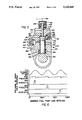
- FIG. 2 is a sectional view showing the novel highpressure pump used in the system
- FIGS. 3A-G are sectional views illustrating the pump at six different sequential points in a cycle of operation
- FIG. 4 is a sectional view showing one of the injector nozzles of the common rail system, with the nozzle being shown in closed position;
- FIG. 5 is a view similar to FIG. 4 with the nozzle shown in the open position under actuation by the nozzle solenoid;
- FIG. 6 is a graph illustrating the pressure at the spray hole entrance, shown at the various degrees of fuel pump cam rotation when the discharge of the various nozzles takes place and shows the slight variation in rail pressure during discharge.
- the system includes an electronic control module 10 (ECM) which sends signals to an electronic distribution unit 12 (EDU).
- ECM electronice control module
- the signals are of low voltage and low power and activate the electronic distribution unit which is connected to a 12-volt vehicle battery 14 by a conductor 16.
- the ECM has at least two electronic inputs, one input A which indicates crank shaft position as a timing reference.
- the other output B indicates throttle position as a load reference.
- Optional inputs are C--turbo boost, D--temperature of oil, E--coolant level, and F--oil pressure.
- the ECM also has a PROM 18 which is programmed by a fuel map developed by actual engine testing.
- the system further includes a fuel-injection pump assembly which is supplied with fuel by a fuel supply pump 22 connected by a line 21 to a fuel tank 23.
- Pump assembly 20 includes two high-pressure fuel-injection pumps 24 and 26, with pump 24 supplying the high-pressure common fuel rail 28, while pump 26 supplies the high-pressure common fuel rail 30 through supply lines 32 and 34, respectively.
- Lines 36 and 38 supply fuel at constant pressure to the high-pressure fuel-injection pumps 24 and 26 from the supply pump 22.
- the high-pressure fuel rail 28 supplies fuel to the injection nozzles 40, 42 and 44 by way of lines 46, 48 and 50, while the high-pressure fuel rail 30 supplies injection nozzles 52, 54 and 56 by way of lines 58, 60 and 62, respectively.
- the pumps have solenoid valves 82 and 84, respectively, which connect through conductors 86 and 88, respectively, to the EDU and are operated by signals the ECM received by way of conductors 86' and 88', respectively.
- the injector nozzles have solenoids 100, 102, 104, 106, 108 and 110 which are operated by the EDU by conductors 112, 114, 116, 118, 120 and 122, respectively, which are in turn controlled by signals sent from the ECM by conductors 112', 114', 116', 118', 120' and 122', respectively.
- FIG. 2 shows the details of construction of fixed displacement pump 24 which is identical to pump 26.
- Pump body 130 houses a pumping chamber 132 within which a pumping plunger 134 reciprocates between fixed top and bottom positions, as will be later described in reference to FIG. 3.
- Fuel is delivered to inlet port 135 of pump 24 by supply line 36.
- Flow of fuel into pumping ,chamber -32 is controlled by inlet valve 136 by fluctuations due to the output pulses of the pump. These fluctuations are small since they are attenuated by the elasticity of the rail structure and volume of high-press fuel. Rail pressure is independent of engine speed.
- Inlet valve 136 includes a stem 140 which mounts the armature 142 of solenoid 82.
- Armature is normally retracted within stator 144 by a compression spring 145, and is extensible upon energization of stator 144 via conductor 86 to open valve inlet port 135.
- the amount of fuel pumped by pump 24 is dependent upon the length of time solenoid 82 is energized and inlet valve 136 is open.
- Fuel delivery from pump 24 is controlled by outlet valve 146 which opens to connect outlet passage 148 which is normally closed by a compression spring 150. Upon opening, valve 146 connects passage 148 with outlet port 152 to enable pressurized flow to delivery line 32.
- Plunger 134 is reciprocated within chamber 132 by a rotating cam 154 between top and bottom positions, thus providing a constant volume pump.
- a bottom flange 156 is maintained in contact with cam 154 by a compression spring 158, confined between flange 156 and a pump body internal wall 160.
- Leakage return line 80 is connected to a leakage fuel inlet port 162 in pump body 130 to deliver leakage fuel to a leakage accumulator chamber 164.
- Chamber 164 houses a piston 166 that is backed by a compression spring 168.
- Leakage fuel accumulated during a pumping cycle is delivered to chamber 132 through leakage chamber outlet passage 170, as will be later described. Any fuel leaking past plunger 134 during a cycle collects in a collector groove 172.
- FIGS. 3A-3D which sequentially depict a pumping cycle.
- the high-pressure pump shown in FIG. 2 is in the same position as the pump shown in FIG. 3A.
- the cycle starts when the plunger is just past top dead center (TDC) with the solenoid off and both the inlet valve 136 and outlet valve 146 are closed by respective springs 145 and 150.
- the inlet valve 136 is opened by the solenoid 82, permitting fuel to flow into the pumping chamber 132.
- the inlet valve 136 is closed by the solenoid 82, halting fuel flow to the pumping chamber 132. The length of time that inlet valve 136 is held open determines how much fuel is metered into the pumping chamber 132.
- One feature of the invention is that fuel accumulated from nozzle and/or plunger leakage is returned to the high-pressure pump without passing through the primary metering valve 136.
- the cam 154 reaches its bottom dead center (BDC) position (FIG. 3E)
- final retraction of the plunger 134 opens the passage 170 to connect the fuel leakage accumulator chamber 164 with the pumping chamber 132.
- the rear of the chamber 164 is maintained at atmospheric pressure to enable the portion of the chamber in front of piston 166 to expand upon pressurization by leakage fuel and serve as an accumulator.
- Many alternate forms of accumulators could also be utilized, including elastic lines, diaphragms, or compressed volume.
- the force of the spring 168 biasing piston 166 and the sub-atmospheric pressure in chamber 164 combine to force the leakage fuel accumulated during the previous engine cycle (i.e., since the last stroke of pump 24) into the pumping chamber 132.
- the quantity of fuel injected on each stroke of the plunger 134 depends on the duration of opening of inlet valve 136 which is controlled by the solenoid 82. Since operation of the solenoid 82 can be precisely controlled, the quantity of fuel pumped can likewise be precisely controlled.
- the fuel injection nozzles 40-44, 52-56 for the common rail fuel injection system are electronically controlled solenoid valves having spray holes which convert the rail pressure head to velocity in the injection plume.
- pressurized fuel is supplied by the high-pressure pumps 24, 26 and stored in the rails 28, 30, or distribution system, which serves as a fuel accumulator.
- FIGS. 4 and 5 show one of the nozzles 40 in the, closed (between injections) and open (during injection) positions, respectively.
- Injector nozzle 40 injects precise amounts of fuel into an engine combustion chamber (not shown) through spray holes 180 as regulated by a pilot-controlled metering valve 182. Pressurized fuel is delivered from rail 28 through delivery line 46 through inlet port 184 to a chamber 186 housing valve 182, which is biased to its normally-closed FIG. 4 position by a compression spring 187.
- Metering valve 182 has a stem 188 which terminates in a throttling stop 190.
- Chamber 186 connects through a passage 192 and an orifice 194 to a pilot chamber 196 atop valve stem 188.
- Chamber 196 connects through a passage 198 to a chamber 200 which connects through a passage 202 to fuel return line 66.
- Another passage 204 connects passage 202 with an annular chamber 206.
- a solenoid-controlled pilot valve 208 has a nose 210, which valves passage 198, and an annular shoulder 212 which confines a spring 214 between it and a housing land 216, biasing valve 208 downwardly to close passage 198.
- Valve 208 includes a stem 218 that mounts a discoid solenoid armature 220 adjacent a solenoid stator 222. Operation of injector 40 will now be described.
- valve 182 With the injection valve 182 closed (FIG. 4), pressurized fuel from the rail 28 flows via line 46 to the nozzle inlet passage 184. Chamber 186 is at rail pressure. In this condition, the solenoid stator 222 is deenergized and the pilot valve 208 is closed by spring 214. With valve 208 closed, there is no flow through passage 198, permitting the fuel in chamber 196 to reach a pressure equal to the pressure in chamber 186, which is rail pressure. With the pressures in the two chambers equal, valve 182 is pressure balanced. The force of the spring 187 acting on valve 182 aids in closing the valve, but is used primarily to keep the valve seated against combustion chamber pressure. Passages 184, 192 and 198 and chambers 186 and 196 are all at rail pressure, and there is no flow through the system.
- solenoid stator 222 is energized, attracting armature 220 toward stator 222 and lifting nose 210 of valve 208 from its seat to open passage 198.
- FIG. 5 shows the nozzle in the valve open condition during injection. With valve nose 210 unseated, flow starts through passage 198, reducing the pressure in chamber 196. Orifice 194, through which fuel from chamber 186 replaces the fuel leaving chamber 196, restricts the flow to create a pressure drop between chambers 186 and 196. With the pressure in chamber 196 less than that in chamber 186, valve 182 becomes pressure unbalanced.
- the pressure imbalance overcomes the force of spring 187 and lifts valve 182 from its seat, enabling pressurized fuel to be ejected through the spray holes 180 and starting fuel injection to the combustion chamber.
- the throttling stop 190 at the end of valve 182 throttles flow into passage 198, while permitting adequate fuel flow through orifice 194 and passage 198 to maintain the pressure imbalance and keep valve 182 open.
- Passages 202 and 204 are provided to drain leakage past valve 208 to the fuel leakage return system via line 66.
- solenoid stator 222 When solenoid stator 222 is deenergized to end fuel injection into the combustion chamber, spring 214 seats valve 182, stopping flow through passage 198. Pressure in chamber 196 increases until the combined force of rail pressure and spring 187 overcome the opposing force caused by combustion pressure and valve 182 closes. Fuel can now no longer flow to the spray holes and injection ends.
- FIG. 6 is a graph showing the pressure at the spray hole entrance of the nozzles 40, 42 and 44 according to degrees of fuel pump cam rotation. It also shows the rail pressure being maintained relatively constant, varying only by fluctuations due to the output pulses of the pump. These fluctuations are small since they are attenuated by the elasticity of the rail structure and volume of high-pressure fuel. Rail pressure is independent of engine speed.
Abstract
Description
Claims (6)
Priority Applications (4)
| Application Number | Priority Date | Filing Date | Title |
|---|---|---|---|
| US07/553,523 US5133645A (en) | 1990-07-16 | 1990-07-16 | Common rail fuel injection system |
| GB9107467A GB2246175B (en) | 1990-07-16 | 1991-04-09 | Common rail fuel injection system |
| DE4115103A DE4115103C2 (en) | 1990-07-16 | 1991-05-08 | High pressure pump for a fuel injection system |
| US07/821,964 US5230613A (en) | 1990-07-16 | 1992-01-16 | Common rail fuel injection system |
Applications Claiming Priority (1)
| Application Number | Priority Date | Filing Date | Title |
|---|---|---|---|
| US07/553,523 US5133645A (en) | 1990-07-16 | 1990-07-16 | Common rail fuel injection system |
Related Child Applications (1)
| Application Number | Title | Priority Date | Filing Date |
|---|---|---|---|
| US07/821,964 Continuation-In-Part US5230613A (en) | 1990-07-16 | 1992-01-16 | Common rail fuel injection system |
Publications (1)
| Publication Number | Publication Date |
|---|---|
| US5133645A true US5133645A (en) | 1992-07-28 |
Family
ID=24209739
Family Applications (1)
| Application Number | Title | Priority Date | Filing Date |
|---|---|---|---|
| US07/553,523 Expired - Lifetime US5133645A (en) | 1990-07-16 | 1990-07-16 | Common rail fuel injection system |
Country Status (3)
| Country | Link |
|---|---|
| US (1) | US5133645A (en) |
| DE (1) | DE4115103C2 (en) |
| GB (1) | GB2246175B (en) |
Cited By (62)
| Publication number | Priority date | Publication date | Assignee | Title |
|---|---|---|---|---|
| US5297523A (en) * | 1993-02-26 | 1994-03-29 | Caterpillar Inc. | Tuned actuating fluid inlet manifold for a hydraulically-actuated fuel injection system |
| WO1994027039A1 (en) * | 1993-05-06 | 1994-11-24 | Cummins Engine Company, Inc. | Variable displacement high pressure pump for common rail fuel injection systems |
| US5421521A (en) * | 1993-12-23 | 1995-06-06 | Caterpillar Inc. | Fuel injection nozzle having a force-balanced check |
| US5538403A (en) * | 1994-05-06 | 1996-07-23 | Cummins Engine Company, Inc. | High pressure pump for fuel injection systems |
| US5628293A (en) * | 1994-05-13 | 1997-05-13 | Caterpillar Inc. | Electronically-controlled fluid injector system having pre-injection pressurizable fluid storage chamber and direct-operated check |
| US5647536A (en) * | 1995-01-23 | 1997-07-15 | Cummins Engine Company, Inc. | Injection rate shaping nozzle assembly for a fuel injector |
| US5673669A (en) * | 1994-07-29 | 1997-10-07 | Caterpillar Inc. | Hydraulically-actuated fluid injector having pre-injection pressurizable fluid storage chamber and direct-operated check |
| US5676114A (en) * | 1996-07-25 | 1997-10-14 | Cummins Engine Company, Inc. | Needle controlled fuel system with cyclic pressure generation |
| US5678521A (en) * | 1993-05-06 | 1997-10-21 | Cummins Engine Company, Inc. | System and methods for electronic control of an accumulator fuel system |
| US5687693A (en) * | 1994-07-29 | 1997-11-18 | Caterpillar Inc. | Hydraulically-actuated fuel injector with direct control needle valve |
| US5697342A (en) * | 1994-07-29 | 1997-12-16 | Caterpillar Inc. | Hydraulically-actuated fuel injector with direct control needle valve |
| US5765755A (en) * | 1997-01-23 | 1998-06-16 | Cummins Engine Company, Inc. | Injection rate shaping nozzle assembly for a fuel injector |
| US5819704A (en) * | 1996-07-25 | 1998-10-13 | Cummins Engine Company, Inc. | Needle controlled fuel system with cyclic pressure generation |
| US5826562A (en) * | 1994-07-29 | 1998-10-27 | Caterpillar Inc. | Piston and barrell assembly with stepped top and hydraulically-actuated fuel injector utilizing same |
| US5860597A (en) * | 1997-03-24 | 1999-01-19 | Cummins Engine Company, Inc. | Injection rate shaping nozzle assembly for a fuel injector |
| US5983863A (en) * | 1993-05-06 | 1999-11-16 | Cummins Engine Company, Inc. | Compact high performance fuel system with accumulator |
| EP0971119A2 (en) * | 1998-07-08 | 2000-01-12 | Isuzu Motors Limited | Common-rail fuel-injection system |
| US6016791A (en) * | 1997-06-04 | 2000-01-25 | Detroit Diesel Corporation | Method and system for controlling fuel pressure in a common rail fuel injection system |
| WO2000006894A1 (en) * | 1998-07-29 | 2000-02-10 | Robert Bosch Gmbh | Fuel supply system of an internal combustion engine |
| US6082332A (en) * | 1994-07-29 | 2000-07-04 | Caterpillar Inc. | Hydraulically-actuated fuel injector with direct control needle valve |
| US6109542A (en) * | 1998-09-21 | 2000-08-29 | Cummins Engine Company, Inc. | Servo-controlled fuel injector with leakage limiting device |
| WO2001044649A1 (en) * | 1999-12-14 | 2001-06-21 | Governors America Corp. | A controlled nozzle injection method and apparatus |
| WO2001086139A1 (en) * | 2000-05-11 | 2001-11-15 | Robert Bosch Gmbh | Method for the operation of a fuel metering system on a direct injection internal combustion engine |
| DE19716750C2 (en) * | 1996-04-17 | 2002-02-14 | Cummins Engine Co Inc | Engine braking system for an internal combustion engine |
| US6357421B1 (en) | 2000-07-18 | 2002-03-19 | Detroit Diesel Corporation | Common rail fuel system |
| US6408821B1 (en) | 2000-12-19 | 2002-06-25 | Caterpillar Inc. | Fuel injection system with common actuation device and engine using same |
| US6425375B1 (en) | 1998-12-11 | 2002-07-30 | Caterpillar Inc. | Piston and barrel assembly with stepped top and hydraulically-actuated fuel injector utilizing same |
| US6439202B1 (en) | 2001-11-08 | 2002-08-27 | Cummins Inc. | Hybrid electronically controlled unit injector fuel system |
| WO2002084108A1 (en) * | 2001-04-10 | 2002-10-24 | Wärtsilä Finland Oy | Fuel injector and method of injecting fuel |
| US6499467B1 (en) | 2000-03-31 | 2002-12-31 | Cummins Inc. | Closed nozzle fuel injector with improved controllabilty |
| US6516782B1 (en) | 1999-05-27 | 2003-02-11 | Detroit Diesel Corporation | System and method for controlling fuel injections |
| US6530363B1 (en) * | 1999-04-16 | 2003-03-11 | Caterpillar Inc | Variable delivery pump and common rail fuel system using the same |
| US6575137B2 (en) | 1994-07-29 | 2003-06-10 | Caterpillar Inc | Piston and barrel assembly with stepped top and hydraulically-actuated fuel injector utilizing same |
| GB2385386A (en) * | 2002-02-15 | 2003-08-20 | Delphi Tech Inc | Pump assembly |
| US6637776B2 (en) | 2001-06-13 | 2003-10-28 | Cummins Inc. | Fluid manifold connector and fluid manifold assembly |
| US20050287021A1 (en) * | 2004-06-24 | 2005-12-29 | Caterpillar Inc. | Variable discharge fuel pump |
| US20060120880A1 (en) * | 2004-11-30 | 2006-06-08 | Caterpillar Inc. | Variable discharge fuel pump |
| US20070012294A1 (en) * | 2005-07-14 | 2007-01-18 | General Electric Company | Common fuel rail fuel system for locomotive engine |
| US7179060B2 (en) | 2002-12-09 | 2007-02-20 | Caterpillar Inc | Variable discharge pump with two pumping plungers and shared shuttle member |
| US20070215113A1 (en) * | 2004-03-18 | 2007-09-20 | Andreas Dutt | High-Pressure Pump for a Fuel Injection System of an Internal Combustion Engine |
| US20080098991A1 (en) * | 2006-10-26 | 2008-05-01 | Caterpillar, Inc. | Selective displacement control of multi-plunger fuel pump |
| US20080105235A1 (en) * | 2006-11-02 | 2008-05-08 | Hisao Ogawa | Fuel injection apparatus for engines |
| US20080109152A1 (en) * | 2006-11-06 | 2008-05-08 | Caterpillar Inc. | Selective displacement control of multi-plunger fuel pump |
| US7380541B1 (en) * | 2006-11-16 | 2008-06-03 | C.R.F. Societa Consortile Per Azioni | Fuel-injection system for an internal-combustion engine |
| US20090078236A1 (en) * | 2007-09-20 | 2009-03-26 | Shawn Michael Gallagher | System and Method for Controlling the Fuel Injection Event in an Internal Combustion Engine |
| US7823566B2 (en) | 2008-03-31 | 2010-11-02 | Caterpillar Inc | Vibration reducing system using a pump |
| CN103189631A (en) * | 2010-11-03 | 2013-07-03 | 罗伯特·博世有限公司 | Fuel injection system and method for filling and/or venting a fuel injection system |
| US20140041634A1 (en) * | 2011-04-19 | 2014-02-13 | Weichai Power Co., Ltd. | Device and method for controlling high-pressure common-rail system of diesel engine |
| CN101713359B (en) * | 2008-10-01 | 2014-03-05 | 曼柴油机欧洲股份公司 | Fuel injection system having a high-pressure pump with a magnetically actuable suction valve |
| US20140165965A1 (en) * | 2012-12-18 | 2014-06-19 | Michael R. Teets | Fuel supply system with accumulator |
| US9156477B2 (en) | 2006-03-20 | 2015-10-13 | General Electric Company | Control system and method for remotely isolating powered units in a vehicle system |
| US20150361926A1 (en) * | 2013-01-23 | 2015-12-17 | Richard Eckhardt | Increased diesel engine efficiency by using nitrous oxide as a fuel additive |
| US9470195B2 (en) | 2012-12-18 | 2016-10-18 | Fca Us Llc | Fuel supply system with accumulator |
| US9669851B2 (en) | 2012-11-21 | 2017-06-06 | General Electric Company | Route examination system and method |
| US9682716B2 (en) | 2012-11-21 | 2017-06-20 | General Electric Company | Route examining system and method |
| US9702715B2 (en) | 2012-10-17 | 2017-07-11 | General Electric Company | Distributed energy management system and method for a vehicle system |
| US9733625B2 (en) | 2006-03-20 | 2017-08-15 | General Electric Company | Trip optimization system and method for a train |
| US9828010B2 (en) | 2006-03-20 | 2017-11-28 | General Electric Company | System, method and computer software code for determining a mission plan for a powered system using signal aspect information |
| US9834237B2 (en) | 2012-11-21 | 2017-12-05 | General Electric Company | Route examining system and method |
| US9950722B2 (en) | 2003-01-06 | 2018-04-24 | General Electric Company | System and method for vehicle control |
| US10308265B2 (en) | 2006-03-20 | 2019-06-04 | Ge Global Sourcing Llc | Vehicle control system and method |
| US10569792B2 (en) | 2006-03-20 | 2020-02-25 | General Electric Company | Vehicle control system and method |
Families Citing this family (10)
| Publication number | Priority date | Publication date | Assignee | Title |
|---|---|---|---|---|
| US5230613A (en) * | 1990-07-16 | 1993-07-27 | Diesel Technology Company | Common rail fuel injection system |
| DE4311627B4 (en) * | 1993-04-08 | 2005-08-25 | Robert Bosch Gmbh | Fuel injection device for internal combustion engines |
| IT1261149B (en) * | 1993-12-30 | 1996-05-09 | Elasis Sistema Ricerca Fiat | DOSING VALVE FOR THE CONTROL OF THE SHUTTER OF A FUEL INJECTOR |
| CH689281A5 (en) * | 1994-02-03 | 1999-01-29 | Christian Dipl-Ing Eth Mathis | Fuel injection system for an internal combustion engine, especially for a diesel engine, and a method for monitoring the same. |
| DE29800346U1 (en) * | 1998-01-12 | 1999-05-12 | Bosch Gmbh Robert | Switching magnet |
| EP1131552B1 (en) * | 1998-11-10 | 2002-11-27 | Ganser-Hydromag Ag | Fuel injection valve for internal combustion engines |
| JP4048699B2 (en) * | 1999-11-10 | 2008-02-20 | 株式会社デンソー | Fuel injection valve |
| DE10160262A1 (en) | 2001-12-07 | 2003-06-18 | Bosch Gmbh Robert | Injector, in particular for common rail injection systems for diesel engines |
| DE102012205342A1 (en) * | 2012-04-02 | 2013-10-02 | Robert Bosch Gmbh | High pressure pump for a fuel injection system |
| CN114278475B (en) * | 2022-01-07 | 2023-12-01 | 龙口龙泵柴油喷射高科有限公司 | Pump rail integrated electric control common rail high-pressure oil supply system assembly |
Citations (29)
| Publication number | Priority date | Publication date | Assignee | Title |
|---|---|---|---|---|
| US1849490A (en) * | 1927-06-24 | 1932-03-15 | Junkers Hugo | Fuel feed pump and method of operating same |
| US2192372A (en) * | 1937-11-18 | 1940-03-05 | Timken Roller Bearing Co | Fuel injection pump |
| US2410517A (en) * | 1940-04-23 | 1946-11-05 | Muller Helmut | Fuel injection pump for internalcombustion engines |
| US2582535A (en) * | 1948-04-14 | 1952-01-15 | Preeision Mecanique Soc | Fuel injection pump |
| US2871796A (en) * | 1955-08-02 | 1959-02-03 | Allis Chalmers Mfg Co | Pilot injection pump |
| US3027843A (en) * | 1955-12-23 | 1962-04-03 | Prec Mecanique | Piston pumps, in particular for feeding fuel to internal combustion engines |
| US3392715A (en) * | 1965-03-17 | 1968-07-16 | Daimler Benz Ag | Device for controlling the pre-injection |
| US3545896A (en) * | 1967-11-15 | 1970-12-08 | Elitex Zavody Textilniho | Reciprocating pump |
| US3630643A (en) * | 1969-02-28 | 1971-12-28 | Bosch Gmbh Robert | Fuel injection pump |
| US4063671A (en) * | 1977-01-07 | 1977-12-20 | Paul Guilden | Film advancing mechanism |
| US4064845A (en) * | 1975-10-22 | 1977-12-27 | Eaton Corporation | Metering valve for pilot fuel injection |
| US4068640A (en) * | 1975-11-01 | 1978-01-17 | The Bendix Corporation | Common rail fuel injection system |
| US4089315A (en) * | 1975-10-03 | 1978-05-16 | Lucas Industries Limited | Fuel injection systems |
| GB2108214A (en) * | 1981-10-15 | 1983-05-11 | Bosch Gmbh Robert | A fuel metering device for fuel injection pump |
| US4426198A (en) * | 1979-05-28 | 1984-01-17 | Societe D'etudes De Thermiques S.E.M.T. | Fuel-injection pump for internal combustion engine |
| GB2122695A (en) * | 1982-06-29 | 1984-01-18 | Bosch Gmbh Robert | Fuel injection pump |
| US4491111A (en) * | 1981-11-07 | 1985-01-01 | Robert Bosch Gmbh | Fuel injection apparatus for internal combustion engines |
| US4505243A (en) * | 1983-07-04 | 1985-03-19 | Nissan Motor Company, Limited | Electromagnetic injection control valve in unit fuel injector |
| US4539956A (en) * | 1982-12-09 | 1985-09-10 | General Motors Corporation | Diesel fuel injection pump with adaptive torque balance control |
| US4579096A (en) * | 1983-12-08 | 1986-04-01 | Toyota Jidosha Kabushiki Kaisha | Diesel fuel injection pump with electromagnetic fuel spilling valve having pilot valve providing high responsiveness |
| US4590904A (en) * | 1983-08-26 | 1986-05-27 | Robert Bosch Gmbh | Fuel injection apparatus |
| US4633837A (en) * | 1984-10-06 | 1987-01-06 | Robert Bosch Gmbh | Method for controlling fuel injection in internal combustion engines and fuel injection system for performing the method |
| US4667638A (en) * | 1984-04-17 | 1987-05-26 | Nippon Soken, Inc. | Fuel injection apparatus for internal combustion engine |
| US4671232A (en) * | 1980-03-22 | 1987-06-09 | Robert Bosch Gmbh | Fuel injection system for self-igniting internal combustion engines |
| US4674448A (en) * | 1985-07-04 | 1987-06-23 | Sulzer Brothers Limited | Fuel injection system for a multi-cylinder reciprocating internal combustion engine |
| US4696271A (en) * | 1984-01-11 | 1987-09-29 | Robert Bosch Gmbh | Fuel injection pump |
| US4767288A (en) * | 1981-06-11 | 1988-08-30 | Robert Bosch Gmbh | Fuel injection pump |
| US4881504A (en) * | 1987-02-13 | 1989-11-21 | Lucas Industries Public Limited Company | Fuel injection pump |
| US5005548A (en) * | 1989-07-06 | 1991-04-09 | Robert Bosch Gmbh | Fuel injection pump |
Family Cites Families (6)
| Publication number | Priority date | Publication date | Assignee | Title |
|---|---|---|---|---|
| BE554051A (en) * | 1956-01-31 | |||
| DE2137832C2 (en) * | 1970-08-10 | 1986-04-17 | Nippondenso Co., Ltd., Kariya, Aichi | Device for injecting fuel into an internal combustion engine |
| DE3019716A1 (en) * | 1980-05-23 | 1981-12-03 | Klöckner-Humboldt-Deutz AG, 5000 Köln | Fuel injection pump for Diesel engine - has centreless cam follower and directly mounted control sleeve |
| MX154828A (en) * | 1981-12-24 | 1987-12-15 | Lucas Ind Plc | IMPROVEMENTS IN A FUEL INJECTION SYSTEM FOR AN INTERNAL COMBUSTION ENGINE |
| DE3429129C2 (en) * | 1984-08-08 | 1995-01-19 | Bosch Gmbh Robert | Dosing device for metering liquid quantities |
| DE3633107A1 (en) * | 1986-04-10 | 1987-10-15 | Bosch Gmbh Robert | FUEL INJECTION DEVICE FOR INTERNAL COMBUSTION ENGINES |
-
1990
- 1990-07-16 US US07/553,523 patent/US5133645A/en not_active Expired - Lifetime
-
1991
- 1991-04-09 GB GB9107467A patent/GB2246175B/en not_active Expired - Fee Related
- 1991-05-08 DE DE4115103A patent/DE4115103C2/en not_active Expired - Fee Related
Patent Citations (29)
| Publication number | Priority date | Publication date | Assignee | Title |
|---|---|---|---|---|
| US1849490A (en) * | 1927-06-24 | 1932-03-15 | Junkers Hugo | Fuel feed pump and method of operating same |
| US2192372A (en) * | 1937-11-18 | 1940-03-05 | Timken Roller Bearing Co | Fuel injection pump |
| US2410517A (en) * | 1940-04-23 | 1946-11-05 | Muller Helmut | Fuel injection pump for internalcombustion engines |
| US2582535A (en) * | 1948-04-14 | 1952-01-15 | Preeision Mecanique Soc | Fuel injection pump |
| US2871796A (en) * | 1955-08-02 | 1959-02-03 | Allis Chalmers Mfg Co | Pilot injection pump |
| US3027843A (en) * | 1955-12-23 | 1962-04-03 | Prec Mecanique | Piston pumps, in particular for feeding fuel to internal combustion engines |
| US3392715A (en) * | 1965-03-17 | 1968-07-16 | Daimler Benz Ag | Device for controlling the pre-injection |
| US3545896A (en) * | 1967-11-15 | 1970-12-08 | Elitex Zavody Textilniho | Reciprocating pump |
| US3630643A (en) * | 1969-02-28 | 1971-12-28 | Bosch Gmbh Robert | Fuel injection pump |
| US4089315A (en) * | 1975-10-03 | 1978-05-16 | Lucas Industries Limited | Fuel injection systems |
| US4064845A (en) * | 1975-10-22 | 1977-12-27 | Eaton Corporation | Metering valve for pilot fuel injection |
| US4068640A (en) * | 1975-11-01 | 1978-01-17 | The Bendix Corporation | Common rail fuel injection system |
| US4063671A (en) * | 1977-01-07 | 1977-12-20 | Paul Guilden | Film advancing mechanism |
| US4426198A (en) * | 1979-05-28 | 1984-01-17 | Societe D'etudes De Thermiques S.E.M.T. | Fuel-injection pump for internal combustion engine |
| US4671232A (en) * | 1980-03-22 | 1987-06-09 | Robert Bosch Gmbh | Fuel injection system for self-igniting internal combustion engines |
| US4767288A (en) * | 1981-06-11 | 1988-08-30 | Robert Bosch Gmbh | Fuel injection pump |
| GB2108214A (en) * | 1981-10-15 | 1983-05-11 | Bosch Gmbh Robert | A fuel metering device for fuel injection pump |
| US4491111A (en) * | 1981-11-07 | 1985-01-01 | Robert Bosch Gmbh | Fuel injection apparatus for internal combustion engines |
| GB2122695A (en) * | 1982-06-29 | 1984-01-18 | Bosch Gmbh Robert | Fuel injection pump |
| US4539956A (en) * | 1982-12-09 | 1985-09-10 | General Motors Corporation | Diesel fuel injection pump with adaptive torque balance control |
| US4505243A (en) * | 1983-07-04 | 1985-03-19 | Nissan Motor Company, Limited | Electromagnetic injection control valve in unit fuel injector |
| US4590904A (en) * | 1983-08-26 | 1986-05-27 | Robert Bosch Gmbh | Fuel injection apparatus |
| US4579096A (en) * | 1983-12-08 | 1986-04-01 | Toyota Jidosha Kabushiki Kaisha | Diesel fuel injection pump with electromagnetic fuel spilling valve having pilot valve providing high responsiveness |
| US4696271A (en) * | 1984-01-11 | 1987-09-29 | Robert Bosch Gmbh | Fuel injection pump |
| US4667638A (en) * | 1984-04-17 | 1987-05-26 | Nippon Soken, Inc. | Fuel injection apparatus for internal combustion engine |
| US4633837A (en) * | 1984-10-06 | 1987-01-06 | Robert Bosch Gmbh | Method for controlling fuel injection in internal combustion engines and fuel injection system for performing the method |
| US4674448A (en) * | 1985-07-04 | 1987-06-23 | Sulzer Brothers Limited | Fuel injection system for a multi-cylinder reciprocating internal combustion engine |
| US4881504A (en) * | 1987-02-13 | 1989-11-21 | Lucas Industries Public Limited Company | Fuel injection pump |
| US5005548A (en) * | 1989-07-06 | 1991-04-09 | Robert Bosch Gmbh | Fuel injection pump |
Non-Patent Citations (8)
| Title |
|---|
| Diesel Locomotives Mechanical Equipment, Article Cooper Bessemer Fuel Pump, pp. 59 62. * |
| Diesel Locomotives-Mechanical Equipment, Article-Cooper-Bessemer Fuel Pump, pp. 59-62. |
| SAE Paper No. 770084 entitled "UFIS--A New Diesel Injection System" By: J. A. Kimberley and R. A. DiDomenico. |
| SAE Paper No. 770084 entitled UFIS A New Diesel Injection System By: J. A. Kimberley and R. A. DiDomenico. * |
| SAE Paper No. 810258 entitled "Electronic Fuel Injection Equipment for Controlled Combustion in Diesel Engines", By: R. K. Cross et al. |
| SAE Paper No. 810258 entitled Electronic Fuel Injection Equipment for Controlled Combustion in Diesel Engines , By: R. K. Cross et al. * |
| SAE Paper No. 840513 entitled "Kompics On A High Bmep Engine" By: K. Komiyama et al. |
| SAE Paper No. 840513 entitled Kompics On A High Bmep Engine By: K. Komiyama et al. * |
Cited By (85)
| Publication number | Priority date | Publication date | Assignee | Title |
|---|---|---|---|---|
| US5297523A (en) * | 1993-02-26 | 1994-03-29 | Caterpillar Inc. | Tuned actuating fluid inlet manifold for a hydraulically-actuated fuel injection system |
| WO1994027039A1 (en) * | 1993-05-06 | 1994-11-24 | Cummins Engine Company, Inc. | Variable displacement high pressure pump for common rail fuel injection systems |
| US5404855A (en) * | 1993-05-06 | 1995-04-11 | Cummins Engine Company, Inc. | Variable displacement high pressure pump for fuel injection systems |
| GB2284024A (en) * | 1993-05-06 | 1995-05-24 | Cummins Engine Co Inc | Variable displacement high pressure pump for common rail fuel injection systems |
| US5983863A (en) * | 1993-05-06 | 1999-11-16 | Cummins Engine Company, Inc. | Compact high performance fuel system with accumulator |
| US5678521A (en) * | 1993-05-06 | 1997-10-21 | Cummins Engine Company, Inc. | System and methods for electronic control of an accumulator fuel system |
| GB2284024B (en) * | 1993-05-06 | 1997-04-02 | Cummins Engine Co Inc | Variable displacement high pressure pump for common rail fuel injection systems |
| US5421521A (en) * | 1993-12-23 | 1995-06-06 | Caterpillar Inc. | Fuel injection nozzle having a force-balanced check |
| US5538403A (en) * | 1994-05-06 | 1996-07-23 | Cummins Engine Company, Inc. | High pressure pump for fuel injection systems |
| US5628293A (en) * | 1994-05-13 | 1997-05-13 | Caterpillar Inc. | Electronically-controlled fluid injector system having pre-injection pressurizable fluid storage chamber and direct-operated check |
| US5673669A (en) * | 1994-07-29 | 1997-10-07 | Caterpillar Inc. | Hydraulically-actuated fluid injector having pre-injection pressurizable fluid storage chamber and direct-operated check |
| US6575137B2 (en) | 1994-07-29 | 2003-06-10 | Caterpillar Inc | Piston and barrel assembly with stepped top and hydraulically-actuated fuel injector utilizing same |
| US5687693A (en) * | 1994-07-29 | 1997-11-18 | Caterpillar Inc. | Hydraulically-actuated fuel injector with direct control needle valve |
| US5697342A (en) * | 1994-07-29 | 1997-12-16 | Caterpillar Inc. | Hydraulically-actuated fuel injector with direct control needle valve |
| US5738075A (en) * | 1994-07-29 | 1998-04-14 | Caterpillar Inc. | Hydraulically-actuated fuel injector with direct control needle valve |
| US6082332A (en) * | 1994-07-29 | 2000-07-04 | Caterpillar Inc. | Hydraulically-actuated fuel injector with direct control needle valve |
| US6065450A (en) * | 1994-07-29 | 2000-05-23 | Caterpillar Inc. | Hydraulically-actuated fuel injector with direct control needle valve |
| US5826562A (en) * | 1994-07-29 | 1998-10-27 | Caterpillar Inc. | Piston and barrell assembly with stepped top and hydraulically-actuated fuel injector utilizing same |
| US5647536A (en) * | 1995-01-23 | 1997-07-15 | Cummins Engine Company, Inc. | Injection rate shaping nozzle assembly for a fuel injector |
| US5769319A (en) * | 1995-01-23 | 1998-06-23 | Cummins Engine Company, Inc. | Injection rate shaping nozzle assembly for a fuel injector |
| DE19716750C2 (en) * | 1996-04-17 | 2002-02-14 | Cummins Engine Co Inc | Engine braking system for an internal combustion engine |
| US5676114A (en) * | 1996-07-25 | 1997-10-14 | Cummins Engine Company, Inc. | Needle controlled fuel system with cyclic pressure generation |
| US5819704A (en) * | 1996-07-25 | 1998-10-13 | Cummins Engine Company, Inc. | Needle controlled fuel system with cyclic pressure generation |
| DE19732447C2 (en) * | 1996-07-25 | 2003-02-13 | Cummins Engine Co Inc | Fuel injection system and method |
| US5765755A (en) * | 1997-01-23 | 1998-06-16 | Cummins Engine Company, Inc. | Injection rate shaping nozzle assembly for a fuel injector |
| US5860597A (en) * | 1997-03-24 | 1999-01-19 | Cummins Engine Company, Inc. | Injection rate shaping nozzle assembly for a fuel injector |
| US6016791A (en) * | 1997-06-04 | 2000-01-25 | Detroit Diesel Corporation | Method and system for controlling fuel pressure in a common rail fuel injection system |
| EP0971119A3 (en) * | 1998-07-08 | 2002-02-13 | Isuzu Motors Limited | Common-rail fuel-injection system |
| EP0971119A2 (en) * | 1998-07-08 | 2000-01-12 | Isuzu Motors Limited | Common-rail fuel-injection system |
| WO2000006894A1 (en) * | 1998-07-29 | 2000-02-10 | Robert Bosch Gmbh | Fuel supply system of an internal combustion engine |
| US6109542A (en) * | 1998-09-21 | 2000-08-29 | Cummins Engine Company, Inc. | Servo-controlled fuel injector with leakage limiting device |
| US6425375B1 (en) | 1998-12-11 | 2002-07-30 | Caterpillar Inc. | Piston and barrel assembly with stepped top and hydraulically-actuated fuel injector utilizing same |
| US6530363B1 (en) * | 1999-04-16 | 2003-03-11 | Caterpillar Inc | Variable delivery pump and common rail fuel system using the same |
| US6516782B1 (en) | 1999-05-27 | 2003-02-11 | Detroit Diesel Corporation | System and method for controlling fuel injections |
| WO2001044649A1 (en) * | 1999-12-14 | 2001-06-21 | Governors America Corp. | A controlled nozzle injection method and apparatus |
| US6499467B1 (en) | 2000-03-31 | 2002-12-31 | Cummins Inc. | Closed nozzle fuel injector with improved controllabilty |
| DE10191335B4 (en) * | 2000-03-31 | 2005-10-20 | Cummins Inc | Closed nozzle fuel injector with improved controllability |
| US20020162536A1 (en) * | 2000-05-11 | 2002-11-07 | Ulrich Steinbrenner | Method for the operation of a fuel metering system on a direct injection internal combustion engine |
| WO2001086139A1 (en) * | 2000-05-11 | 2001-11-15 | Robert Bosch Gmbh | Method for the operation of a fuel metering system on a direct injection internal combustion engine |
| US6823844B2 (en) | 2000-05-11 | 2004-11-30 | Robert Bosch Gmbh | Method for the operation of a fuel metering system on a direct injection internal combustion engine |
| US6357421B1 (en) | 2000-07-18 | 2002-03-19 | Detroit Diesel Corporation | Common rail fuel system |
| US6520151B2 (en) | 2000-12-19 | 2003-02-18 | Caterpillar Inc | Fuel injection system with common actuation device and engine using same |
| US6408821B1 (en) | 2000-12-19 | 2002-06-25 | Caterpillar Inc. | Fuel injection system with common actuation device and engine using same |
| WO2002084108A1 (en) * | 2001-04-10 | 2002-10-24 | Wärtsilä Finland Oy | Fuel injector and method of injecting fuel |
| US6637776B2 (en) | 2001-06-13 | 2003-10-28 | Cummins Inc. | Fluid manifold connector and fluid manifold assembly |
| US6439202B1 (en) | 2001-11-08 | 2002-08-27 | Cummins Inc. | Hybrid electronically controlled unit injector fuel system |
| GB2385386A (en) * | 2002-02-15 | 2003-08-20 | Delphi Tech Inc | Pump assembly |
| US7179060B2 (en) | 2002-12-09 | 2007-02-20 | Caterpillar Inc | Variable discharge pump with two pumping plungers and shared shuttle member |
| US20070086899A1 (en) * | 2002-12-09 | 2007-04-19 | Sommars Mark F | Fuel system with variable discharge pump |
| US9950722B2 (en) | 2003-01-06 | 2018-04-24 | General Electric Company | System and method for vehicle control |
| US20070215113A1 (en) * | 2004-03-18 | 2007-09-20 | Andreas Dutt | High-Pressure Pump for a Fuel Injection System of an Internal Combustion Engine |
| US7363913B2 (en) * | 2004-03-18 | 2008-04-29 | Robert Bosch Gmbh | High-pressure pump for a fuel injection system of an internal combustion engine |
| US20050287021A1 (en) * | 2004-06-24 | 2005-12-29 | Caterpillar Inc. | Variable discharge fuel pump |
| US7517200B2 (en) | 2004-06-24 | 2009-04-14 | Caterpillar Inc. | Variable discharge fuel pump |
| US20060120880A1 (en) * | 2004-11-30 | 2006-06-08 | Caterpillar Inc. | Variable discharge fuel pump |
| US7470117B2 (en) | 2004-11-30 | 2008-12-30 | Caterpillar Inc. | Variable discharge fuel pump |
| US20070012294A1 (en) * | 2005-07-14 | 2007-01-18 | General Electric Company | Common fuel rail fuel system for locomotive engine |
| US7234449B2 (en) * | 2005-07-14 | 2007-06-26 | General Electric Company | Common fuel rail fuel system for locomotive engine |
| US10569792B2 (en) | 2006-03-20 | 2020-02-25 | General Electric Company | Vehicle control system and method |
| US10308265B2 (en) | 2006-03-20 | 2019-06-04 | Ge Global Sourcing Llc | Vehicle control system and method |
| US9156477B2 (en) | 2006-03-20 | 2015-10-13 | General Electric Company | Control system and method for remotely isolating powered units in a vehicle system |
| US9828010B2 (en) | 2006-03-20 | 2017-11-28 | General Electric Company | System, method and computer software code for determining a mission plan for a powered system using signal aspect information |
| US9733625B2 (en) | 2006-03-20 | 2017-08-15 | General Electric Company | Trip optimization system and method for a train |
| US20080098991A1 (en) * | 2006-10-26 | 2008-05-01 | Caterpillar, Inc. | Selective displacement control of multi-plunger fuel pump |
| US8015964B2 (en) | 2006-10-26 | 2011-09-13 | David Norman Eddy | Selective displacement control of multi-plunger fuel pump |
| US20080105235A1 (en) * | 2006-11-02 | 2008-05-08 | Hisao Ogawa | Fuel injection apparatus for engines |
| US7415972B2 (en) * | 2006-11-02 | 2008-08-26 | Mitsubishi Heavy Industries, Ltd. | Fuel injection apparatus for engines |
| US7406949B2 (en) * | 2006-11-06 | 2008-08-05 | Caterpillar Inc. | Selective displacement control of multi-plunger fuel pump |
| US20080109152A1 (en) * | 2006-11-06 | 2008-05-08 | Caterpillar Inc. | Selective displacement control of multi-plunger fuel pump |
| US7380541B1 (en) * | 2006-11-16 | 2008-06-03 | C.R.F. Societa Consortile Per Azioni | Fuel-injection system for an internal-combustion engine |
| US20090078236A1 (en) * | 2007-09-20 | 2009-03-26 | Shawn Michael Gallagher | System and Method for Controlling the Fuel Injection Event in an Internal Combustion Engine |
| US7630823B2 (en) | 2007-09-20 | 2009-12-08 | General Electric Company | System and method for controlling the fuel injection event in an internal combustion engine |
| US7823566B2 (en) | 2008-03-31 | 2010-11-02 | Caterpillar Inc | Vibration reducing system using a pump |
| CN101713359B (en) * | 2008-10-01 | 2014-03-05 | 曼柴油机欧洲股份公司 | Fuel injection system having a high-pressure pump with a magnetically actuable suction valve |
| CN103189631A (en) * | 2010-11-03 | 2013-07-03 | 罗伯特·博世有限公司 | Fuel injection system and method for filling and/or venting a fuel injection system |
| CN103189631B (en) * | 2010-11-03 | 2016-09-14 | 罗伯特·博世有限公司 | Fuel injection system and for the filling of fuel injection system and/or the method for emptying |
| US9664157B2 (en) * | 2011-04-19 | 2017-05-30 | Weichai Power Co., Ltd. | Device and method for controlling high-pressure common-rail system of diesel engine |
| US20140041634A1 (en) * | 2011-04-19 | 2014-02-13 | Weichai Power Co., Ltd. | Device and method for controlling high-pressure common-rail system of diesel engine |
| US9702715B2 (en) | 2012-10-17 | 2017-07-11 | General Electric Company | Distributed energy management system and method for a vehicle system |
| US9669851B2 (en) | 2012-11-21 | 2017-06-06 | General Electric Company | Route examination system and method |
| US9682716B2 (en) | 2012-11-21 | 2017-06-20 | General Electric Company | Route examining system and method |
| US9834237B2 (en) | 2012-11-21 | 2017-12-05 | General Electric Company | Route examining system and method |
| US9470195B2 (en) | 2012-12-18 | 2016-10-18 | Fca Us Llc | Fuel supply system with accumulator |
| US20140165965A1 (en) * | 2012-12-18 | 2014-06-19 | Michael R. Teets | Fuel supply system with accumulator |
| US20150361926A1 (en) * | 2013-01-23 | 2015-12-17 | Richard Eckhardt | Increased diesel engine efficiency by using nitrous oxide as a fuel additive |
Also Published As
| Publication number | Publication date |
|---|---|
| GB9107467D0 (en) | 1991-05-22 |
| GB2246175B (en) | 1994-02-16 |
| GB2246175A (en) | 1992-01-22 |
| DE4115103A1 (en) | 1992-04-02 |
| DE4115103C2 (en) | 1997-10-23 |
Similar Documents
| Publication | Publication Date | Title |
|---|---|---|
| US5133645A (en) | Common rail fuel injection system | |
| US5230613A (en) | Common rail fuel injection system | |
| US5035221A (en) | High pressure electronic common-rail fuel injection system for diesel engines | |
| US5109822A (en) | High pressure electronic common-rail fuel injection system for diesel engines | |
| US5143291A (en) | Two-stage hydraulic electrically-controlled unit injector | |
| US5463996A (en) | Hydraulically-actuated fluid injector having pre-injection pressurizable fluid storage chamber and direct-operated check | |
| US4628881A (en) | Pressure-controlled fuel injection for internal combustion engines | |
| USRE33270E (en) | Pressure-controlled fuel injection for internal combustion engines | |
| KR100373616B1 (en) | High-pressure fuel pump and cam for high-pressure fuel pump | |
| US7377266B2 (en) | Integrated fuel feed apparatus | |
| US5423484A (en) | Injection rate shaping control ported barrel for a fuel injection system | |
| US7198034B2 (en) | Method and system for the direct injection of fuel into an internal combustion engine | |
| US7574995B2 (en) | Fuel injection system | |
| JP2000356156A (en) | Common rail type fuel injection device | |
| JPH09209867A (en) | Fuel injector | |
| GB2327714A (en) | A unit fuel injector with a needle control valve | |
| EP0517991B1 (en) | High pressure electronic common-rail fuel injection system for diesel engines | |
| KR20010067290A (en) | An electronic controlled diesel fuel injection system | |
| US6029628A (en) | Electric-operated fuel injection having de-coupled supply and drain passages to and from an intensifier piston | |
| US6725840B1 (en) | Fuel injection device | |
| US6000379A (en) | Electronic fuel injection quiet operation | |
| EP0340807B1 (en) | Method and apparatus for precisely controlled fuel injection in internal combustion engine | |
| US20050045149A1 (en) | Fuel injection system | |
| RU2273764C2 (en) | Injection system | |
| US20070217925A1 (en) | Variable discharge pump |
Legal Events
| Date | Code | Title | Description |
|---|---|---|---|
| AS | Assignment |
Owner name: DIESEL TECHNOLOGY CORPORATION, A CORP OF DE, MICH Free format text: ASSIGNMENT OF ASSIGNORS INTEREST.;ASSIGNORS:CROWLEY, PATRICK J.;HILSBOS, RICHARD L.;WIELAND, HAROLD L.;AND OTHERS;REEL/FRAME:005373/0204 Effective date: 19900710 |
|
| AS | Assignment |
Owner name: DIESEL TECHNOLOGY COMPANY, MICHIGAN Free format text: ASSIGNMENT OF ASSIGNORS INTEREST.;ASSIGNOR:DIESEL TECHNOLOGY CORPORATION;REEL/FRAME:006122/0110 Effective date: 19920409 |
|
| STCF | Information on status: patent grant |
Free format text: PATENTED CASE |
|
| CC | Certificate of correction | ||
| FPAY | Fee payment |
Year of fee payment: 4 |
|
| FPAY | Fee payment |
Year of fee payment: 8 |
|
| FEPP | Fee payment procedure |
Free format text: PAYOR NUMBER ASSIGNED (ORIGINAL EVENT CODE: ASPN); ENTITY STATUS OF PATENT OWNER: LARGE ENTITY |
|
| FPAY | Fee payment |
Year of fee payment: 12 |