US5137367A - Automated paint production apparatus - Google Patents
Automated paint production apparatus Download PDFInfo
- Publication number
- US5137367A US5137367A US07/590,242 US59024290A US5137367A US 5137367 A US5137367 A US 5137367A US 59024290 A US59024290 A US 59024290A US 5137367 A US5137367 A US 5137367A
- Authority
- US
- United States
- Prior art keywords
- container
- mixing
- lane
- containers
- shuttle
- Prior art date
- Legal status (The legal status is an assumption and is not a legal conclusion. Google has not performed a legal analysis and makes no representation as to the accuracy of the status listed.)
- Expired - Fee Related
Links
- 238000004519 manufacturing process Methods 0.000 title claims description 18
- 239000003973 paint Substances 0.000 title description 26
- 238000002156 mixing Methods 0.000 claims abstract description 145
- 239000004615 ingredient Substances 0.000 claims abstract description 17
- 238000011144 upstream manufacturing Methods 0.000 claims abstract description 12
- 230000033001 locomotion Effects 0.000 claims description 32
- 238000007599 discharging Methods 0.000 claims description 5
- 230000007246 mechanism Effects 0.000 abstract description 48
- 230000000712 assembly Effects 0.000 abstract description 5
- 238000000429 assembly Methods 0.000 abstract description 5
- 238000004806 packaging method and process Methods 0.000 abstract description 4
- 239000000047 product Substances 0.000 description 15
- 239000000203 mixture Substances 0.000 description 13
- 238000009472 formulation Methods 0.000 description 11
- 239000000463 material Substances 0.000 description 11
- 239000000654 additive Substances 0.000 description 2
- 238000013459 approach Methods 0.000 description 2
- 239000004568 cement Substances 0.000 description 2
- 239000003795 chemical substances by application Substances 0.000 description 2
- 238000010276 construction Methods 0.000 description 2
- 239000000945 filler Substances 0.000 description 2
- 239000012263 liquid product Substances 0.000 description 2
- 238000002360 preparation method Methods 0.000 description 2
- 238000003908 quality control method Methods 0.000 description 2
- 230000003068 static effect Effects 0.000 description 2
- 239000004593 Epoxy Substances 0.000 description 1
- CWYNVVGOOAEACU-UHFFFAOYSA-N Fe2+ Chemical compound [Fe+2] CWYNVVGOOAEACU-UHFFFAOYSA-N 0.000 description 1
- 230000000996 additive effect Effects 0.000 description 1
- 238000000576 coating method Methods 0.000 description 1
- 239000003086 colorant Substances 0.000 description 1
- 238000006073 displacement reaction Methods 0.000 description 1
- 238000009826 distribution Methods 0.000 description 1
- 238000009434 installation Methods 0.000 description 1
- 239000007788 liquid Substances 0.000 description 1
- 239000011344 liquid material Substances 0.000 description 1
- 238000000034 method Methods 0.000 description 1
- 230000000284 resting effect Effects 0.000 description 1
- 238000007789 sealing Methods 0.000 description 1
- 238000003860 storage Methods 0.000 description 1
- 238000006467 substitution reaction Methods 0.000 description 1
- 239000002699 waste material Substances 0.000 description 1
Images


Classifications
-
- B—PERFORMING OPERATIONS; TRANSPORTING
- B01—PHYSICAL OR CHEMICAL PROCESSES OR APPARATUS IN GENERAL
- B01F—MIXING, e.g. DISSOLVING, EMULSIFYING OR DISPERSING
- B01F31/00—Mixers with shaking, oscillating, or vibrating mechanisms
- B01F31/20—Mixing the contents of independent containers, e.g. test tubes
- B01F31/22—Mixing the contents of independent containers, e.g. test tubes with supporting means moving in a horizontal plane, e.g. describing an orbital path for moving the containers about an axis which intersects the receptacle axis at an angle
-
- B—PERFORMING OPERATIONS; TRANSPORTING
- B01—PHYSICAL OR CHEMICAL PROCESSES OR APPARATUS IN GENERAL
- B01F—MIXING, e.g. DISSOLVING, EMULSIFYING OR DISPERSING
- B01F35/00—Accessories for mixers; Auxiliary operations or auxiliary devices; Parts or details of general application
- B01F35/71—Feed mechanisms
-
- B—PERFORMING OPERATIONS; TRANSPORTING
- B01—PHYSICAL OR CHEMICAL PROCESSES OR APPARATUS IN GENERAL
- B01F—MIXING, e.g. DISSOLVING, EMULSIFYING OR DISPERSING
- B01F31/00—Mixers with shaking, oscillating, or vibrating mechanisms
-
- B—PERFORMING OPERATIONS; TRANSPORTING
- B01—PHYSICAL OR CHEMICAL PROCESSES OR APPARATUS IN GENERAL
- B01F—MIXING, e.g. DISSOLVING, EMULSIFYING OR DISPERSING
- B01F35/00—Accessories for mixers; Auxiliary operations or auxiliary devices; Parts or details of general application
- B01F35/10—Maintenance of mixers
-
- Y—GENERAL TAGGING OF NEW TECHNOLOGICAL DEVELOPMENTS; GENERAL TAGGING OF CROSS-SECTIONAL TECHNOLOGIES SPANNING OVER SEVERAL SECTIONS OF THE IPC; TECHNICAL SUBJECTS COVERED BY FORMER USPC CROSS-REFERENCE ART COLLECTIONS [XRACs] AND DIGESTS
- Y10—TECHNICAL SUBJECTS COVERED BY FORMER USPC
- Y10S—TECHNICAL SUBJECTS COVERED BY FORMER USPC CROSS-REFERENCE ART COLLECTIONS [XRACs] AND DIGESTS
- Y10S366/00—Agitating
- Y10S366/605—Paint mixer
Definitions
- the present invention pertains to apparatus for the automated production of paint and other materials which are dispensed into a container, and with closure of the container are mixed by agitating the container.
- Products which are composed of several ingredients are often produced by combining ingredients in a shipping or storage container, sealing the container and then mixing the contents thereof.
- pulverulant products such as cement mixes or liquid products such as paints and coatings are readily amenable to such production techniques.
- a can, pail or other suitable container is filled with a base material.
- the containers may have a five gallon or a one gallon capacity, for example. Thereafter, one or more tinting agents are injected or otherwise added to the base material.
- a paint base material may be tinted at a local business establishment conveniently accessible to an end user, using materials provided by a paint manufacturer.
- the tinting agents and possibly other additives are added to a paint base material, and the container is then sealed and inserted into a mixing apparatus which shakes or otherwise moves the container to mix the contents thereof. It is important that the ingredients of a paint formulation be thoroughly mixed to provide a uniform color value throughout the container contents.
- Such mixing may be performed, for example, by bench top units or, less commonly, by floor mounted units both of which are manually operated by store personnel who insure that the container is securely clamped within the mixing apparatus, and who set the desired amount of time for a mixing operation.
- the operator unclamps the container from the apparatus and presents the container to the end user, with no further operations being required in most cases.
- Paint is also manufactured by tinting a base material in a mass production facility.
- Such "factory formulations" are important, for example, when large quantities of a formulated paint are required, or when certain quality controls are required, especially for unusual paint formulations. Also, depending upon the distribution system available and other factors, additional economies of production are possible only with large-scale factory operations.
- the containers may be provided with bar-code indicia which contain paint formulation and other information such as the size of the container and customer information associated with an order for the paint material.
- bar-code indicia which contain paint formulation and other information such as the size of the container and customer information associated with an order for the paint material.
- Another object according to the present invention is to provide automated mixing apparatus which can receive a series of containers from a conveyor line.
- a further object according to the present invention is to provide automated mixing apparatus which mixes the contents of several containers at one time.
- a further object according to the present invention is to provide multiple mixing facilities at a mixing station, along with means for routing the containers to one facility or the other.
- processing lanes between the input and output support surfaces for transporting containers therebetween;
- lane guide means between said input support surface and said processing lanes, selectably movable to selectably guide containers carried by said input support surface to a particular processing lane for mixing thereat;
- each mixing station including a frame means for movably supporting a container for movement in a mixing motion, container clamping means for selectably clamping the container within said frame means to maintain engagement therewith during a mixing operation, and drive means for moving said frame means with a mixing motion so as to agitate the contents of a container clamped therein; and
- loading means in each processing lane for loading a container guided by said lane guide means in the frame means.
- FIG. 1 is a top plan view of an automatic mixing station illustrating principles according to the present invention
- FIG. 2 is an enlarged, fragmentary perspective view of the paint mixing apparatus of FIG. 1;
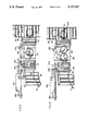
- FIG. 3 is a side elevational view of the automatic mixing station of FIG. 1;
- FIG. 4 is a fragmentary plan view of the automatic mixing station of FIG. 1, shown on an enlarged scale;
- FIG. 5 is a fragmentary plan view of the automatic mixing station of FIG. 1;
- FIG. 6 is a fragmentary side elevational view of the mixing apparatus showing a shuttle arm assembly thereof;
- FIG. 7 is a fragmentary plan view of the shuttle arm assembly of FIG. 6.
- FIG. 8 is a fragmentary plan view showing a loading of two containers on the mixing apparatus.
- the mixing station 10 includes an inlet conveyor 12 and an exit conveyor 14.
- a series of containers 18 holding contents to be mixed are introduced to the mixing station by conveyor 12, and are directed, either individually, in pairs, or four at a time to one of two mixing mechanisms 20, 22.
- the containers, after being mixed, are passed to exit conveyor 14 where they continue on in the production cycle.
- the present invention may be used to mix a variety of materials which are packaged in closed containers, ready for shipment to an end user.
- the present invention may be used, for example, with liquid products, mixtures of liquid and pulverulant products, such as block fillers, and with pulverulant products such as cement mixes.
- the present invention finds immediate application in an automated paint manufacturing facility wherein one or more colorants are added to a paint base, the ingredients of a paint formulation being introduced directly into containers 18.
- the containers are sealed at a lidding station 30 located upstream of mixing station 10 where the containers are sealed, preparatory to the mixing operation.
- the sealed containers enter an input support surface 13 of restricted width which accurately positions the containers with respect to the mixing apparatus.
- the sealed containers then enter a wider, intermediate conveyor 32.
- the intermediate conveyor 32 is several times wider than the feed conveyor 12 or support surface 13, the conveyor 32 spanning the entrance conveyors 38, 40 associated with mixing mechanisms 20, 22, respectively.
- a lane guide mechanism or diverter Located in an upstream portion of conveyor 32 is a lane guide mechanism or diverter generally indicated at 44.
- the diverter includes a gate 46 pivotally mounted at 48 to a drive mechanism, as will be explained with reference to FIG. 2.
- the gate 46 is moveable between the two positions illustrated in FIG. 1, one position illustrated in solid lines, the other illustrated in phantom.
- the diverter gate 46 guides containers 18 along one of two processing lanes or product paths, each associated with one of the two mixing mechanisms.
- a pair of diverging guide walls 50, 52 are located immediately downstream of diverter 44, and terminate at chutes 56, 58, respectively, formed by wall portions 60, 62 which are aligned generally parallel to outer rails 64, 66 located at lateral edges of conveyor 32.
- the chutes 56, 58 are aligned with the entrance conveyors 38, 40 which together cooperate to align containers 18 in the mixing mechanisms 20, 22.
- Output support surfaces 70,72 formed of static rollers are located between the mixing mechanisms 20, 22 and exit conveyor 14. If desired, the rollers of the output support surfaces may be power driven to assist the discharge of the containers.
- input support surface 13 comprising a series of rollers 76 which are aligned coplanar with the rollers 78 of conveyor 32, and which are also aligned with the inlet conveyor 12.
- the rollers 76, 78 are power driven by a belt 79 (see FIG. 3).
- the belt travels in the direction of arrow 81, so as to transport containers 18 in the downstream direction of arrow 80.
- the conveyors 38, 40 are also comprised of a series of laterally extending rollers, aligned coplanar with the tables 82, 84 of mixing mechanisms 20, 22, respectively (see FIG. 1).
- the rollers of conveyors 38, 40 are not powered (and are thus unlike the other conveyor sections), so as to stop the containers at a defined location, in preparation for engagement with the shuttle arm.
- gate 46 is secured at one end to pivot support 48 which includes a shaft 88 extending to an electric motor operator 90, supported above conveyor 32 by lateral channels 92, 94.
- Motor 90 may either comprise a stepper motor or may include mechanical gearing at its output shaft so as to rotate shaft 88 a predetermined amount, moving gate 46 between the two positions indicated in FIGS. 1 and 2.
- gate 46 is swung in a counterclockwise direction (as viewed from a point above conveyor 32), directing containers 18 toward mixing mechanism 20 and onto the table 82 thereof.
- Rollers 78 are preferably power driven moving container 18 in the downstream direction of arrow 80.
- the rails 26, align the containers along a center line of conveyor 32.
- container 18 contacts gate 46 and slides along the gate, being guided thereby.
- the container continues its downstream travel, passing along wall 50, entering an area of the mixing station where feed mechanisms, one for each product path, aid in propelling the container toward the mixing mechanism, as will be explained below.
- motor 90 is rotated in an opposite direction, moving gate 46 to the position indicated in phantom in FIG. 2, ready to guide containers 18 to the other mixing mechanism 22, and onto the table 84 thereof.
- the mixing apparatus can accommodate multiple containers (preferably either two or four) at a mixing station.
- FIG. 8 illustrates two containers in position at mixing station 20. The containers are mixed simultaneously, and are thereafter discharged to exit conveyor 14.
- the mixing stations 20 and 22 include a mixing mechanism 100 consisting of a moveable platform, such as the platform 84, and an upper pressure plate 104 which clamps the containers 18 in position on the moveable table, maintaining the containers captive during a mixing operation.
- Framework 106 for the clamping plate is mounted at its lower end to table 108 which provides a convenient mounting for the mixing apparatus and the entrance conveyor 40.
- An hydraulic cylinder 110 extends in a downward direction, having a base secured to framework 106 and a piston 112 connected to pressure plate 104.
- hydraulic cylinder 110 When containers 18 are moved in position on table 84, hydraulic cylinder 110 is pressurized to extend plate 104 to its lowered, clamping position, in engagement with one or more containers 18.
- An electric motor 116 is mounted to table 108 and has an output shaft connected to mechanism, not shown, for moving table 84 in an orbital path.
- the hydraulic cylinder 110 is pinned at 120 to frame 106, and piston 112 is connected with a swivel mounting to plate 104, to follow the orbital motion.
- the motor and mixing mechanism is adapted from a Model 5G mixer, Part No. 12147 available from Miller Limited Partnership of Addison, Ill.
- the mixer marketed for use in a manual operation, was adapted for the fully automatic operation described herein, the frame 106 and clamping plate 104 being added thereto, for example.
- the piston 112 is retracted by hydraulic cylinder 110 to release clamping plate 104.
- the containers are then discharged to conveyor 14.
- the mixing apparatus 10 includes a pair of assemblies, generally indicated at 124, 126, located on opposite sides of intermediate conveyor 32.
- the assemblies 124, 126 are mirror images of one another, being comprised of similar parts except for the oppositely directed shuttle arms.
- shuttle arm assembly 126 includes a pair of guide rails 130, 134 and an intermediate screw shaft 132.
- a shuttle generally indicated at 140 travels along the guide rails, being reciprocated back and forth in the direction of arrow 142 as shaft 132 is rotated.
- Shaft 132 is driven by an electric motor 144 mounted to support 136.
- Motor 144 preferably comprises a stepper motor, although other motors having a controlled operation may also be used.
- Shuttle 140 includes a body with a vertical plate 150 and slide bushings 152, 154 which engage guide bars 130, 134.
- a threaded bushing 158 engages threaded shaft 132 and converts the rotation of the shaft to a linear displacement in the directions of arrow 142.
- a retractable shuttle arm 160 is pinned at 162 to a support leg 164 secured to the lower end of vertical plate 150. The shuttle arm 160 is free to pivot in the direction of arrow 168 (see FIG. 2). The arm 160 is biased toward its undeflected position, illustrated in phantom in FIG. 1 and, also in FIGS. 4 and 6.
- the shuttle 140 is advanced toward drive motor 144 so as to move shuttle arm 160 to a retracted position, with the V-shaped contact member 161 in the path of travel of container 18 which is advanced along the guide wall.
- the arm is deflected toward the support rail assembly in the manner indicated in FIG. 1, allowing the passage of container 18 past the shuttle arm.
- the power-driven rollers 78 of intermediate conveyor 32 continue to advance container 18 in a downstream direction of arrow 170, clearing the contact member and thus allowing the shuttle arm 160 to return to its undeflected position, illustrated in phantom in FIG. 1.
- the container 18 continues to travel in the downstream direction, being guided by wall 62 until it reaches the last power driven roller 78 of intermediate conveyor 32, at the upstream end of the static entrance conveyor 40.
- a plurality of sensors are disposed adjacent the product path, so as to monitor the position of shuttle arm 160 therealong.
- the sensors are mounted on a support 174 extending along one side of intermediate conveyor 32.
- a first sensor 176 is located at an upstream position
- second and third sensors 178, 180 are located at intermediate positions
- an optional (associated with container ejection) sensor 182 is located at a downstream position.
- a projection 184 of ferrous material extends from one end of shuttle arm 160, so as to be placed in close proximity to the sensors 176-182 as the arm travels throughout its range of motion.
- projection 184 is located proximate to sensor 176, sending an electrical signal to control unit 186, advising control circuitry therein of the position of the shuttle arm.
- the shuttle 140 is allowed to travel along threaded rod 132 until projection 184 (carried on arm 160) is sensed at sensor 180.
- the control circuitry in control unit 186 responding to signals from sensor 180, reverses the direction of shuttle movement, causing the shuttle and the shuttle arm 160 to move to the upstream, retracted position.
- Sensor 180 is located a precise distance upstream of table 84 such that a container 18 is centered on table 84 when projection 184 is detected at sensor 180, the container being moved to the position as illustrated in FIG. 1.
- the intermediate sensor 178 is used when two or more containers are loaded at entrance conveyor 40, the shuttle arm 160 pushing both containers into position on moveable table 84, the arm being stopped when projection 184 is detected at sensor 178.
- a similar positioning is illustrated in FIG. 1 at station 20.
- the guide rails extend past the mixing mechanisms to a point adjacent exit conveyor 14. This extension which may be omitted if desired, cooperates with sensor 182 to provide an ejection of containers at the mixing mechanism.
- the shuttle arm assembly 124 is substantially identical to the aforedescribed shuttle arm assembly 126, except that the V-shaped contact member of 192 shuttle arm 190 opens in an opposite direction from the aforedescribed contact member 161, generally comprising a mirror image thereof.
- the motor, guide rails and shuttle assembly are the same as those used in shuttle arm assembly 126.
- a pair of containers 18 are loaded onto the table 82 of mixing station 20.
- a container 18 is deflected by gate 46, and travels along guide walls 50, 60.
- a shuttle arm 190 is immediately moved to its fully retracted position, opposite guide wall 50. As the container passes shuttle arm 190, the arm is retracted to allow the container to pass the arm, toward its temporary resting position at the upstream end of entrance conveyor 38.
- the drive motor is activated by control circuit 196 which receives signals from a series of sensors 200-206. Signals from sensor 200 indicate that a projection 210 carried by shuttle arm 190 is located proximate the sensor 200, with the arm being located at a fully retracted position.
- the threaded shaft moves shuttle arm 190 in the downstream direction toward table 82.
- the contact member 192 carried on arm 190 approaches entrance conveyor 40, it engages a container 18.
- the container is pushed onto table 82, as illustrated in FIG. 5.
- sensor 202 detects the presence of projection 210, further travel of the arm is stopped, and the motor is reversed to retract the shuttle arm away from table 82. Thereafter, the clamping plate at mixer station 82 is lowered and table 82 is driven with an orbital motion, mixing the contents of container 18 loaded thereon.
- the pressure plate is raised and the shuttle arm 190 is again advanced in a downstream direction, through the position illustrated in FIG. 5.
- the shuttle arm 190 is further advanced in a downstream direction along an extended guide rail to the position illustrated in phantom in FIG. 5, with the presence of projection 210 being detected by sensor 206.
- Signals from sensor 206 cause control unit 196 to respond by reversing the direction of motor 144, moving shuttle arm 190 to the fully retracted position illustrated in FIG. 1, ready for another operation.
- the contact member 192 is withdrawn away from container 18, and the container is free to move in the downstream direction of arrow 214.
- two containers may be mixed at station 20, at one time.
- the gate 46 is maintained in the position illustrated in FIG. 4, after a first container arrives at entrance conveyor 38, the second container travelling in the same direction illustrated in FIG. 4.
- control unit 196 energizes motor 144 to move shuttle arm to the position illustrated in FIG. 8, with projection 210 being moved proximate to sensor 202.
- Signals from sensor 202 received by control unit 196 cause motor 144 to reverse, retracting the shuttle arm 190 away from the containers loaded on table 82.
- the pressure plate of the mixing station is thereafter lowered, clamping the containers in preparation for a mixing operation. Thereafter, clamping is released and motor 144 is again energized, moving shuttle arm 190 to the position illustrated in phantom in FIG. 8, with projection 210 triggering sensor 206 to send signals to control unit 196, indicating that the ejection operation has been completed, and that the shuttle arm should be returned in an opposite direction to its retracted position.
- Conveyor 14 is power driven, to move containers in the direction of arrow 214.
- the leading container is free to move in the downstream direction of arrow 214.
- contact member 192 is moved away from conveyor 14, and the second container 18 is also free to move in a downstream direction, at a position spaced from the leading container, as illustrated in FIG. 8.
- the guide walls 60, 62 can be moved toward one another to widen the product paths to allow pairs of containers 18 to pass side-by-side.
- the shuttle arms With the arrival of a second pair of containers at entrance conveyors 38 or 40, the shuttle arms are moved to push four containers at a time onto tables 82, 84.
- a pair of contact members 161 or 192 be carried at the ends of the shuttle arms, to form a W-configuration (rather than the aforedescribed V-shaped configuration) for pushing pairs of containers arranged side-by-side, at one time.
- a single lidding station can accommodate container ingredients of different types, requiring different mixing times or different mixing motions, for example.
- the containers with the differing ingredients can be interlaced on the inlet conveyor, the diverter 44 directing containers with ingredients of a particular type to the appropriate mixing mechanism. That is, the mixing mechanisms of the two product paths need not be identical, but can vary in operating time, direction of mixing motion, or other construction details.
- the mixing station may be called upon to mixing an epoxy paint or other two-part formulation, with the containers on exit conveyor 14 being associated in pairs, ready of packaging and shipment.
- Containers with the "Part A” ingredients can be passed along one product path to be mixed in a first mixing mechanism, with the "Part B” ingredients being mixed in the other mechanism, substantially simultaneously therewith.
- the two containers are discharged onto conveyor 14.
- the container in mixing mechanism 20 can be held briefly, while the container in mixing mechanism 22 is discharged by output surface 72 onto exit conveyor 14. As the container approaches the output support surface 70, the container in mechanism 20 is released for discharge onto conveyor 14, in close proximity to the container discharge for mechanism 22.
- the container discharged from mechanism 84 can be allowed to travel past output support surface 70 before the container in mechanism 20 is discharged onto conveyor 14, the order of the containers being reversed for presentation to a downstream packaging station.
- the flexibility of the automatic mixing apparatus according to the present invention is particularly important where the ingredients of one part of a two-part mixture contain a filler or other additive which is more difficult to mix, possibly requiring longer mixing times.
- different formulations can be interleaved at the entrance conveyor 12 with diverter gate 46 being operated to alternately direct containers to one or the other mixing mechanism.
- the containers can be interleaved in a random fashion on inlet conveyor 12, and can pass to the mixing mechanisms without delay.
- scanning apparatus can identify a particular paint formulation and can forward the information contained on the bar code label, for example, to the mixing mechanism to specify a custom mixing intensity or duration, for example.
- the bar code information could also be passed to a downstream packaging station or downstream diverter apparatus which could segregate formulations of a particular type.
- mixing apparatus is particularly advantageous in maximizing the throughput of an automated mixing station. If an optimum throughput rate is not required, scanning apparatus can be installed along inlet conveyor 12, directing the diverter gate 46 to a particular mixing mechanism, depending upon information carried on the container.
- each mixing mechanism can be discharged to its own separate exit conveyor if such is useful from a product handling standpoint.
- orbital mixers have been described above, and are preferred for their ready availability and reliability of operation, other types of mixing mechanisms could also be employed.
- the shuttle arms 160, 190 are pivotably retractable, being deflected by a travelling container moving therepast. If desired, the shuttle arms can be moved even further upstream, out of contact with containers travelling along the diverging guide walls 50 or 52, and the arms need not be retractable in that instance.
- diverter gate is installed in each entrance conveyor 38, 40, the conveyors being widened to accept two containers, side-by-side, at one time.
- a diverter gate at the entrance conveyors 38, 40 can pair successive containers in the desired manner and can provide reliable operation without significantly increasing the cost or size of the mixing station.
- mixing apparatus constructed according to principles of the present invention can be fully automated and is readily incorporated in fully automated paint manufacturing equipment, such as that provided by the assignee of the present invention, as described above.
Abstract
Description
Claims (18)
Priority Applications (9)
| Application Number | Priority Date | Filing Date | Title |
|---|---|---|---|
| US07/590,242 US5137367A (en) | 1990-09-28 | 1990-09-28 | Automated paint production apparatus |
| EP91308502A EP0478211A1 (en) | 1990-09-28 | 1991-09-18 | Automated paint production apparatus |
| CA002051950A CA2051950A1 (en) | 1990-09-28 | 1991-09-20 | Automated paint production apparatus |
| AU84672/91A AU636245B2 (en) | 1990-09-28 | 1991-09-20 | Automated paint production apparatus |
| BR919104172A BR9104172A (en) | 1990-09-28 | 1991-09-27 | AUTOMATED APPLIANCE FOR MIXING INGREDIENTS STORED IN CLOSED CONTAINERS |
| KR1019910016911A KR920006026A (en) | 1990-09-28 | 1991-09-27 | Device for mixing components stored in airtight containers |
| FI914561A FI914561A (en) | 1990-09-28 | 1991-09-27 | AUTOMATISERAD ANORDNING FOER FRAMSTAELLNING AV MAOLFAERG. |
| MX9101313A MX173899B (en) | 1990-09-28 | 1991-09-27 | AUTOMATED PAINT PRODUCTION APPARATUS |
| JP3252017A JPH07121352B2 (en) | 1990-09-28 | 1991-09-30 | Device for automatically mixing components stored in closed containers |
Applications Claiming Priority (1)
| Application Number | Priority Date | Filing Date | Title |
|---|---|---|---|
| US07/590,242 US5137367A (en) | 1990-09-28 | 1990-09-28 | Automated paint production apparatus |
Publications (1)
| Publication Number | Publication Date |
|---|---|
| US5137367A true US5137367A (en) | 1992-08-11 |
Family
ID=24361449
Family Applications (1)
| Application Number | Title | Priority Date | Filing Date |
|---|---|---|---|
| US07/590,242 Expired - Fee Related US5137367A (en) | 1990-09-28 | 1990-09-28 | Automated paint production apparatus |
Country Status (9)
| Country | Link |
|---|---|
| US (1) | US5137367A (en) |
| EP (1) | EP0478211A1 (en) |
| JP (1) | JPH07121352B2 (en) |
| KR (1) | KR920006026A (en) |
| AU (1) | AU636245B2 (en) |
| BR (1) | BR9104172A (en) |
| CA (1) | CA2051950A1 (en) |
| FI (1) | FI914561A (en) |
| MX (1) | MX173899B (en) |
Cited By (29)
| Publication number | Priority date | Publication date | Assignee | Title |
|---|---|---|---|---|
| US6412658B1 (en) | 2001-06-01 | 2002-07-02 | Imx Labs, Inc. | Point-of-sale body powder dispensing system |
| US6615881B2 (en) | 2001-09-24 | 2003-09-09 | Imx Labs, Inc. | Apparatus and method for custom cosmetic dispensing |
| US6622064B2 (en) | 2000-03-31 | 2003-09-16 | Imx Labs, Inc. | Nail polish selection method |
| US6672341B2 (en) | 2001-09-24 | 2004-01-06 | Imx Labs, Inc. | Apparatus and method for custom cosmetic dispensing |
| US6729754B1 (en) * | 2002-09-05 | 2004-05-04 | Red Devil Equipment Corporation | Paint container lifting attachment for paint mixers |
| US20040218466A1 (en) * | 2002-09-05 | 2004-11-04 | Red Devil Equipment | Lifting apparatus for paint mixers |
| US20080269950A1 (en) * | 2004-06-30 | 2008-10-30 | Cps Color Equipment Spa Con Unico Socio | Device and Method for Mixing a Fluid Product Contained in a Closed Container |
| US7624769B2 (en) | 2004-11-08 | 2009-12-01 | Cosmetic Technologies, L.L.C. | Automated customized cosmetic dispenser |
| US20090316521A1 (en) * | 2008-06-20 | 2009-12-24 | Red Devil Equipment Company | Pounding station |
| US20110010255A1 (en) * | 2009-07-10 | 2011-01-13 | Mario Drocco | Dispensing and mixing line and method for products |
| US8017137B2 (en) | 2004-07-19 | 2011-09-13 | Bartholomew Julie R | Customized retail point of sale dispensing methods |
| US20130158704A1 (en) * | 2011-12-16 | 2013-06-20 | Randall L. Hughes | Method and apparatus for producing paint |
| US8573263B2 (en) | 2001-09-24 | 2013-11-05 | Cosmetic Technologies, Llc | Apparatus and method for custom cosmetic dispensing |
| US8636173B2 (en) | 2001-06-01 | 2014-01-28 | Cosmetic Technologies, L.L.C. | Point-of-sale body powder dispensing system |
| US9284130B1 (en) | 2014-10-10 | 2016-03-15 | Goodrich Corporation | Multi-zone load leveling system for air cushion supported aircraft cargo loading robot |
| US20160101857A1 (en) * | 2014-10-10 | 2016-04-14 | Goodrich Corporation | Slide bushing supported aircraft cargo loading systems and methods |
| US9352835B2 (en) | 2014-10-10 | 2016-05-31 | Goodrich Corporation | Wedge lift jacking system for crawler supported aircraft loading robot |
| US9387931B2 (en) | 2014-10-10 | 2016-07-12 | Goodrich Corporation | Air cushion aircraft cargo loading systems and shuttle drive unit |
| US9511861B2 (en) | 2014-10-10 | 2016-12-06 | Goodrich Corporation | Noise reduction barrier for air cushion supported aircraft cargo loading robot |
| US9511860B2 (en) | 2014-10-10 | 2016-12-06 | Goodrich Corporation | Air cushion aircraft cargo loading systems and wireless communication unit |
| US9555888B2 (en) | 2014-10-10 | 2017-01-31 | Goodrich Corporation | Pressure compensating air curtain for air cushion supported cargo loading platform |
| US9567166B2 (en) | 2014-10-10 | 2017-02-14 | Goodrich Corporation | Compact centrifugal air blowers for air cushion supported cargo loading platform |
| US9580250B2 (en) | 2015-01-30 | 2017-02-28 | Goodrich Corporation | Bushing cleaner systems and methods |
| US9764840B2 (en) | 2014-10-10 | 2017-09-19 | Goodrich Corporation | Air cushion aircraft cargo loading systems and wireless charging unit |
| US10196146B2 (en) | 2014-10-10 | 2019-02-05 | Goodrich Corporation | Self propelled air cushion supported aircraft cargo loading systems and methods |
| US10393225B2 (en) | 2015-01-05 | 2019-08-27 | Goodrich Corporation | Integrated multi-function propulsion belt for air cushion supported aircraft cargo loading robot |
| WO2019236243A1 (en) * | 2018-06-06 | 2019-12-12 | Walmart Apollo, Llc | Automated paint machine with custom order capability |
| CN113171713A (en) * | 2021-04-20 | 2021-07-27 | 南城县晨风香料有限公司 | Even agitated vessel is used in pure vegetable oil pesticide solvent processing production |
| US11412835B2 (en) | 2015-06-08 | 2022-08-16 | Cosmetic Technologies, L.L.C. | Automated delivery system of a cosmetic sample |
Families Citing this family (6)
| Publication number | Priority date | Publication date | Assignee | Title |
|---|---|---|---|---|
| JP2002338851A (en) * | 2001-05-15 | 2002-11-27 | Kikusui Chemical Industries Co Ltd | Color matching system |
| CN100368067C (en) * | 2003-02-18 | 2008-02-13 | 泰克诺拉玛有限责任公司 | Apparatus of dye operation in textile material |
| ITFI20030015U1 (en) * | 2003-02-18 | 2004-08-19 | Tecnorama Srl | EQUIPMENT TO PERFORM DYEING OPERATIONS ON TEXTILE MATERIALS |
| DE102006042504A1 (en) * | 2006-09-07 | 2008-03-27 | CFS Bühl GmbH | Method and device for stringing packaging trays |
| CN102837959B (en) * | 2012-07-03 | 2015-04-22 | 山东洛杰斯特物流科技有限公司 | Cigarette diversion and supplying device |
| JP7432223B2 (en) * | 2019-12-27 | 2024-02-16 | 株式会社石野製作所 | Ordered food and drink conveyor |
Citations (4)
| Publication number | Priority date | Publication date | Assignee | Title |
|---|---|---|---|---|
| US2036421A (en) * | 1932-11-12 | 1936-04-07 | Edward B Luckie | Method and apparatus for inserting bottles in boxes |
| US2542451A (en) * | 1950-02-08 | 1951-02-20 | United Co | Can shaking device |
| US3462912A (en) * | 1967-07-19 | 1969-08-26 | Cherry Burrell Corp | Orientor for cans to be loaded into cases |
| US3848394A (en) * | 1973-06-26 | 1974-11-19 | R Heisler | Apparatus and method for orienting and case packing eared containers |
Family Cites Families (6)
| Publication number | Priority date | Publication date | Assignee | Title |
|---|---|---|---|---|
| FR517237A (en) * | 1920-06-16 | 1921-05-02 | Forderanlagen Ernst Heckel Ges | Device for changing the direction of travel and removing bundled goods from the conveyor aprons |
| US1376273A (en) * | 1920-12-31 | 1921-04-26 | Earl L Hansell | Liquid-mixing machine |
| DE460119C (en) * | 1926-08-20 | 1928-05-21 | Dulche Loading Machine Company | Machine for inserting bottles in transport boxes |
| DE1756220A1 (en) * | 1968-04-23 | 1970-05-14 | Piesteritz Stickstoff | Device for the automatic sliding frictionless palletizing of prismatic and circular cylindrical bodies, in particular of packaging containers with high weight and low inherent strength |
| US3599789A (en) * | 1969-08-05 | 1971-08-17 | Mojonnier Bros Co | High-speed case-sorting apparatus |
| GB2192138B (en) * | 1986-07-01 | 1990-08-22 | Merris Dev Engineers Limited | Vibratory mixers |
-
1990
- 1990-09-28 US US07/590,242 patent/US5137367A/en not_active Expired - Fee Related
-
1991
- 1991-09-18 EP EP91308502A patent/EP0478211A1/en not_active Withdrawn
- 1991-09-20 AU AU84672/91A patent/AU636245B2/en not_active Ceased
- 1991-09-20 CA CA002051950A patent/CA2051950A1/en not_active Abandoned
- 1991-09-27 FI FI914561A patent/FI914561A/en not_active Application Discontinuation
- 1991-09-27 BR BR919104172A patent/BR9104172A/en not_active Application Discontinuation
- 1991-09-27 KR KR1019910016911A patent/KR920006026A/en not_active Application Discontinuation
- 1991-09-27 MX MX9101313A patent/MX173899B/en not_active IP Right Cessation
- 1991-09-30 JP JP3252017A patent/JPH07121352B2/en not_active Expired - Lifetime
Patent Citations (4)
| Publication number | Priority date | Publication date | Assignee | Title |
|---|---|---|---|---|
| US2036421A (en) * | 1932-11-12 | 1936-04-07 | Edward B Luckie | Method and apparatus for inserting bottles in boxes |
| US2542451A (en) * | 1950-02-08 | 1951-02-20 | United Co | Can shaking device |
| US3462912A (en) * | 1967-07-19 | 1969-08-26 | Cherry Burrell Corp | Orientor for cans to be loaded into cases |
| US3848394A (en) * | 1973-06-26 | 1974-11-19 | R Heisler | Apparatus and method for orienting and case packing eared containers |
Cited By (62)
| Publication number | Priority date | Publication date | Assignee | Title |
|---|---|---|---|---|
| US8352070B2 (en) | 2000-03-31 | 2013-01-08 | Cosmetic Technologies, Llc | Nail polish color selection system |
| US7822504B2 (en) | 2000-03-31 | 2010-10-26 | Cosmetic Technologies, L.L.C. | Nail polish color selection system |
| US6622064B2 (en) | 2000-03-31 | 2003-09-16 | Imx Labs, Inc. | Nail polish selection method |
| US8880218B2 (en) | 2000-03-31 | 2014-11-04 | Cosmetic Technologies, L.L.C. | Nail polish color selection system |
| US7395134B2 (en) | 2000-03-31 | 2008-07-01 | Cosmetic Technologies, L.L.C. | Nail polish color selection system |
| US7099740B2 (en) | 2000-03-31 | 2006-08-29 | Bartholomew Julie R | Nail polish color selection system |
| US6779686B2 (en) | 2001-06-01 | 2004-08-24 | Imx Labs, Inc. | Point-of-sale body powder dispensing system |
| US6412658B1 (en) | 2001-06-01 | 2002-07-02 | Imx Labs, Inc. | Point-of-sale body powder dispensing system |
| US7121429B2 (en) | 2001-06-01 | 2006-10-17 | Bartholomew Julie R | Point-of-sale body powder dispensing system |
| US8636173B2 (en) | 2001-06-01 | 2014-01-28 | Cosmetic Technologies, L.L.C. | Point-of-sale body powder dispensing system |
| US6672341B2 (en) | 2001-09-24 | 2004-01-06 | Imx Labs, Inc. | Apparatus and method for custom cosmetic dispensing |
| US8141596B2 (en) | 2001-09-24 | 2012-03-27 | Cosmetic Technologies Llc | Apparatus and method for custom cosmetic dispensing |
| US6883561B2 (en) | 2001-09-24 | 2005-04-26 | Imx Labs, Inc. | Apparatus and method for custom cosmetic dispensing |
| US8573263B2 (en) | 2001-09-24 | 2013-11-05 | Cosmetic Technologies, Llc | Apparatus and method for custom cosmetic dispensing |
| US7082970B2 (en) | 2001-09-24 | 2006-08-01 | Bartholomew Julie R | Apparatus and method for custom cosmetic dispensing |
| US20040108015A1 (en) * | 2001-09-24 | 2004-06-10 | Imx Labs, Inc. | Apparatus and method for custom cosmetic dispensing |
| US6615881B2 (en) | 2001-09-24 | 2003-09-09 | Imx Labs, Inc. | Apparatus and method for custom cosmetic dispensing |
| US7475710B2 (en) | 2001-09-24 | 2009-01-13 | Bartholomew Julie R | Apparatus and method for custom cosmetic dispensing |
| US7044632B2 (en) * | 2002-09-05 | 2006-05-16 | Red Devil Equipment Company | Lifting apparatus for paint mixers |
| US6729754B1 (en) * | 2002-09-05 | 2004-05-04 | Red Devil Equipment Corporation | Paint container lifting attachment for paint mixers |
| US20040190370A1 (en) * | 2002-09-05 | 2004-09-30 | Red Devil Equipment Company | Lifting assist arm for paint mixer |
| US6926436B2 (en) * | 2002-09-05 | 2005-08-09 | Red Devil Equipment Company | Lifting assist arm for paint mixer |
| US20040218466A1 (en) * | 2002-09-05 | 2004-11-04 | Red Devil Equipment | Lifting apparatus for paint mixers |
| US20080269950A1 (en) * | 2004-06-30 | 2008-10-30 | Cps Color Equipment Spa Con Unico Socio | Device and Method for Mixing a Fluid Product Contained in a Closed Container |
| US7890213B2 (en) * | 2004-06-30 | 2011-02-15 | Cps Color Equipment Spa Con Unico Socio | Device and method for mixing a fluid product contained in a closed container |
| US8017137B2 (en) | 2004-07-19 | 2011-09-13 | Bartholomew Julie R | Customized retail point of sale dispensing methods |
| US8608371B2 (en) | 2004-11-08 | 2013-12-17 | Cosmetic Technologies, Llc | Automated customized cosmetic dispenser |
| US8186872B2 (en) | 2004-11-08 | 2012-05-29 | Cosmetic Technologies | Automated customized cosmetic dispenser |
| US9691213B2 (en) | 2004-11-08 | 2017-06-27 | Cosmetic Technologies, L.L.C. | Automated customized cosmetic dispenser |
| US9984526B2 (en) | 2004-11-08 | 2018-05-29 | Cosmetic Technologies, L.L.C. | Automated customized cosmetic dispenser |
| US7624769B2 (en) | 2004-11-08 | 2009-12-01 | Cosmetic Technologies, L.L.C. | Automated customized cosmetic dispenser |
| US8182136B2 (en) * | 2008-06-20 | 2012-05-22 | Red Devil Equipment Company | Pounding station for a paint mixer |
| US20090316521A1 (en) * | 2008-06-20 | 2009-12-24 | Red Devil Equipment Company | Pounding station |
| CN101954257B (en) * | 2009-07-10 | 2014-07-23 | 马里奥·德罗科 | Line for dispensing and mixing products and related method |
| US20110010255A1 (en) * | 2009-07-10 | 2011-01-13 | Mario Drocco | Dispensing and mixing line and method for products |
| CN101954257A (en) * | 2009-07-10 | 2011-01-26 | 马里奥·德罗科 | The distribution and mixture operation line and the method thereof that are used for product |
| US8936390B2 (en) * | 2011-12-16 | 2015-01-20 | Microblend Technologies, Inc. | Method and apparatus for producing paint |
| US20150124553A1 (en) * | 2011-12-16 | 2015-05-07 | Microblend Technologies, Inc. | Method and apparatus for producing paint |
| US9211514B2 (en) * | 2011-12-16 | 2015-12-15 | Microblend Technologies, Inc. | Method and apparatus for producing paint |
| US20130158704A1 (en) * | 2011-12-16 | 2013-06-20 | Randall L. Hughes | Method and apparatus for producing paint |
| US9511860B2 (en) | 2014-10-10 | 2016-12-06 | Goodrich Corporation | Air cushion aircraft cargo loading systems and wireless communication unit |
| US10196146B2 (en) | 2014-10-10 | 2019-02-05 | Goodrich Corporation | Self propelled air cushion supported aircraft cargo loading systems and methods |
| US9511861B2 (en) | 2014-10-10 | 2016-12-06 | Goodrich Corporation | Noise reduction barrier for air cushion supported aircraft cargo loading robot |
| US9352835B2 (en) | 2014-10-10 | 2016-05-31 | Goodrich Corporation | Wedge lift jacking system for crawler supported aircraft loading robot |
| US9555888B2 (en) | 2014-10-10 | 2017-01-31 | Goodrich Corporation | Pressure compensating air curtain for air cushion supported cargo loading platform |
| US9567166B2 (en) | 2014-10-10 | 2017-02-14 | Goodrich Corporation | Compact centrifugal air blowers for air cushion supported cargo loading platform |
| US9387931B2 (en) | 2014-10-10 | 2016-07-12 | Goodrich Corporation | Air cushion aircraft cargo loading systems and shuttle drive unit |
| US9643723B2 (en) * | 2014-10-10 | 2017-05-09 | Goodrich Corporation | Slide bushing supported aircraft cargo loading systems and methods |
| US20160101857A1 (en) * | 2014-10-10 | 2016-04-14 | Goodrich Corporation | Slide bushing supported aircraft cargo loading systems and methods |
| US9764840B2 (en) | 2014-10-10 | 2017-09-19 | Goodrich Corporation | Air cushion aircraft cargo loading systems and wireless charging unit |
| US9776720B2 (en) | 2014-10-10 | 2017-10-03 | Goodrich Corporation | Air cushion aircraft cargo loading systems and wireless communication unit |
| US9784276B2 (en) | 2014-10-10 | 2017-10-10 | Goodrich Corporation | Compact centrifugal air blowers for air cushion supported cargo loading platform |
| US9783299B2 (en) | 2014-10-10 | 2017-10-10 | Goodrich Corporation | Pressure compensating air curtain for air cushion supported cargo loading platform |
| US9783298B2 (en) | 2014-10-10 | 2017-10-10 | Goodrich Corporation | Noise reduction barrier for air cushion supported aircraft cargo loading robot |
| US9284130B1 (en) | 2014-10-10 | 2016-03-15 | Goodrich Corporation | Multi-zone load leveling system for air cushion supported aircraft cargo loading robot |
| US10005557B2 (en) | 2014-10-10 | 2018-06-26 | Goodrich Corporation | Pressure compensating air curtain for air cushion supported cargo loading platform |
| US10393225B2 (en) | 2015-01-05 | 2019-08-27 | Goodrich Corporation | Integrated multi-function propulsion belt for air cushion supported aircraft cargo loading robot |
| US9580250B2 (en) | 2015-01-30 | 2017-02-28 | Goodrich Corporation | Bushing cleaner systems and methods |
| US11412835B2 (en) | 2015-06-08 | 2022-08-16 | Cosmetic Technologies, L.L.C. | Automated delivery system of a cosmetic sample |
| WO2019236243A1 (en) * | 2018-06-06 | 2019-12-12 | Walmart Apollo, Llc | Automated paint machine with custom order capability |
| US10940452B2 (en) | 2018-06-06 | 2021-03-09 | Walmart Apollo, Llc | Automated paint machine with custom order capability |
| CN113171713A (en) * | 2021-04-20 | 2021-07-27 | 南城县晨风香料有限公司 | Even agitated vessel is used in pure vegetable oil pesticide solvent processing production |
Also Published As
| Publication number | Publication date |
|---|---|
| CA2051950A1 (en) | 1992-03-29 |
| JPH04265139A (en) | 1992-09-21 |
| EP0478211A1 (en) | 1992-04-01 |
| FI914561A (en) | 1992-03-29 |
| BR9104172A (en) | 1992-06-02 |
| AU636245B2 (en) | 1993-04-22 |
| FI914561A0 (en) | 1991-09-27 |
| MX173899B (en) | 1994-04-07 |
| KR920006026A (en) | 1992-04-27 |
| JPH07121352B2 (en) | 1995-12-25 |
| AU8467291A (en) | 1992-04-02 |
Similar Documents
| Publication | Publication Date | Title |
|---|---|---|
| US5137367A (en) | Automated paint production apparatus | |
| US5116134A (en) | Automated paint production apparatus | |
| KR890004134Y1 (en) | Apparatus for piling portland cement packages in alignment on platform | |
| US5027869A (en) | Dispensing method and apparatus, and container transporting apparatus | |
| FI60997C (en) | FOERFARANDE OCH ANORDNING FOER INFOERANDE AV EN PRODUKT SOM SKALL FOERPACKAS I EN BEHAOLLARE | |
| US3346239A (en) | Combined material mixer and distributor | |
| US3721331A (en) | Side discharge belt conveyor assembly | |
| US5588276A (en) | Sleeving machine | |
| US4487308A (en) | Apparatus for the transport of packs | |
| CN210681408U (en) | Code spraying device for packaging bag | |
| US3693776A (en) | Pusher loading means for conveyors | |
| EP1257487B1 (en) | A system for transporting containers, which is especially suitable for use in a plant for the production of paints, varnishes and the like | |
| RU2016813C1 (en) | Semiautomatic device for batching loose materials by volume | |
| CN218968102U (en) | Flocculant is prepared with carrying turning device | |
| US3807124A (en) | Packaging apparatus | |
| US3549001A (en) | Feed conveyor | |
| JP3247740B2 (en) | Weighing device | |
| CN218595453U (en) | Distribution transmission device | |
| AU2001234086A1 (en) | A system for transporting containers, which is especially suitable for use in a plant for the production of paints, varnishes and the like | |
| SU1082733A1 (en) | Apparatus for unloading plate-like articles from multiple-holder containers | |
| GB2136410A (en) | Machine for use in handling containers | |
| CN116081264A (en) | Flocculant is prepared with carrying turning device | |
| IE66383B1 (en) | A method and a conveyor assembly for assembling components onto a base | |
| DE4314783A1 (en) | Device for handling objects during transport, in particular through filling and / or packaging systems | |
| JPH0755791B2 (en) | Foreign object sorting device |
Legal Events
| Date | Code | Title | Description |
|---|---|---|---|
| AS | Assignment |
Owner name: FLUID MANAGEMENT LIMITED PARTNERSHIP, 605 SOUTH WH Free format text: ASSIGNMENT OF ASSIGNORS INTEREST.;ASSIGNORS:MADONIA, KENNETH J.;DWYER, NILES M.;REEL/FRAME:005564/0506 Effective date: 19901126 |
|
| AS | Assignment |
Owner name: DUNN-EDWARDS CORPORATION, A CORP. OF CA, CALIFORNI Free format text: ASSIGNMENT OF ASSIGNORS INTEREST.;ASSIGNOR:FLUID MANAGEMENT LIMITED PARTNERSHIP, BY FLUID MANAGEMENT, INC., MANAGING GENERAL PARTER;REEL/FRAME:006158/0340 Effective date: 19920520 |
|
| REFU | Refund |
Free format text: REFUND OF EXCESS PAYMENTS PROCESSED (ORIGINAL EVENT CODE: R169); ENTITY STATUS OF PATENT OWNER: LARGE ENTITY |
|
| FPAY | Fee payment |
Year of fee payment: 4 |
|
| AS | Assignment |
Owner name: FM ACQUISITION CORP., ILLINOIS Free format text: ASSIGNMENT OF ASSIGNORS INTEREST;ASSIGNOR:FLUID MANAGEMENT LIMITED PARTNERSHIP;REEL/FRAME:008167/0747 Effective date: 19960729 |
|
| AS | Assignment |
Owner name: FLUID MANAGEMENT, INC., ILLINOIS Free format text: CHANGE OF NAME;ASSIGNOR:FM ACQUISITION CORP.;REEL/FRAME:008194/0004 Effective date: 19960807 |
|
| REMI | Maintenance fee reminder mailed | ||
| LAPS | Lapse for failure to pay maintenance fees | ||
| FP | Lapsed due to failure to pay maintenance fee |
Effective date: 20000811 |
|
| STCH | Information on status: patent discontinuation |
Free format text: PATENT EXPIRED DUE TO NONPAYMENT OF MAINTENANCE FEES UNDER 37 CFR 1.362 |