US5138661A - Linear predictive codeword excited speech synthesizer - Google Patents
Linear predictive codeword excited speech synthesizer Download PDFInfo
- Publication number
- US5138661A US5138661A US07/612,056 US61205690A US5138661A US 5138661 A US5138661 A US 5138661A US 61205690 A US61205690 A US 61205690A US 5138661 A US5138661 A US 5138661A
- Authority
- US
- United States
- Prior art keywords
- codeword
- speech
- linear predictive
- signal
- pitch
- Prior art date
- Legal status (The legal status is an assumption and is not a legal conclusion. Google has not performed a legal analysis and makes no representation as to the accuracy of the status listed.)
- Expired - Lifetime
Links
Images


Classifications
-
- G—PHYSICS
- G10—MUSICAL INSTRUMENTS; ACOUSTICS
- G10L—SPEECH ANALYSIS OR SYNTHESIS; SPEECH RECOGNITION; SPEECH OR VOICE PROCESSING; SPEECH OR AUDIO CODING OR DECODING
- G10L13/00—Speech synthesis; Text to speech systems
- G10L13/02—Methods for producing synthetic speech; Speech synthesisers
Definitions
- This invention generally relates to digital voice transmission systems and, more particularly, to a low complexity speech coder.
- CELP Code Excited Linear Prediction
- MPLPC Multi-pulse Linear Predictive Coding
- DOD Department of Defense
- LPC linear predictive coding
- J.D. Markel and A.H. Gray A description of the standard LPC vocoder is provided by J.D. Markel and A.H. Gray in "A Linear Prediction Vocoder Simulation Based Upon The Autocorrelation Method", IEEE Trans. on Acoustics. Speech, and Sional Processing, Vol. ASSP-22, No. 2, April 1974, pp. 124-134.
- CELP holds the most promise for high quality, its computational requirements can be too great for some systems.
- MPLPC can be implemented with much less complexity, but it is generally considered to provide lower quality than CELP.
- the basic technique comprises searching a codebook of randomly distributed excitation vectors for that vector that produces an output sequence (when filtered through pitch and linear predictive coding (LPC) short-term synthesis filters) that is closest to the input sequence.
- LPC linear predictive coding
- all of the candidate excitation vectors in the codebook must be filtered with both the pitch and LPC synthesis filters to produce a candidate output sequence that can then be compared to the input sequence.
- CELP a very computationally-intensive algorithm, with typical codebooks consisting of 1024 entries, each 40 samples long.
- a perceptual error weighting filter is usually employed, which adds to the computational load.
- FIG. 1 A block diagram of a known implementation of the CELP algorithm is shown in FIG. 1, and FIG. 2 shows some example waveforms illustrating operation of the CELP method. These figures are described below to better illustrate the CELP system.
- Multi-pulse coding was first described by B.S. Atal and J.R. Remde in "A New Model of LPC Excitation for Producing Natural Sounding Speech at Low Bit Rates", Proc. of 1982 IEEE Int Conf. on Acoustics, Speech. and Signal Processing, May 1982, pp. 614-617. It was described as an improvement on the rather synthetic quality of the speech produced by the standard DOD LPC-10 vocoder.
- the basic method is to employ the LPC speech synthesis filter of the standard vocoder, but to excite the filter with multiple pulses per pitch period, instead of the single pulse as in the DOD standard system.
- the basic multi-pulse technique is illustrated in FIG. 3, and FIG. 4 shows some example waveforms illustrating the operation of the MPLPC method. These figures are described below to better illustrate the MPLPC system.
- the CELP algorithm has probably been the most favored algorithm; however, the CELP algorithm is very complex in terms of computational requirements and would be too expensive to implement in a commercial product any time in the near future.
- the LPC-10 vocoder algorithm is the government standard for speech coding at 2.4 Kbit/sec. This algorithm is relatively simple, but speech quality is only fair, and it does not adapt well to 4.8 Kbit/sec use. The need, therefore, is for a speech coder which performs significantly better than the LPC-10 vocoder, and for other, significantly less complex alternatives to CELP, at 4.8 Kbit/sec rates.
- an object of the present invention to provide a speech coder that performs well at 4.8 Kbits/sec, without excessive complexity.
- Another object is to provide a speech coder employing a codebook of small enough size that its memory and processing requirements are kept to a practical level.
- a linear predictive codeword excited synthesizer (LPCES) of speech is provided with features common to both the LPC-10 and CELP coders.
- the LPCES performs a voiced/unvoiced decision to determine the type of excitation to be fed to the synthesis filter.
- the LPCES coder selects the excitation for voiced speech from a codebook, using an analysis-by-synthesis technique. Because of the small size of the codebook used by the LPCES coder, its memory and processing requirements are kept within a practical level.
- the LPCES coder is more robust than the LPC-10 coder and produces higher quality speech, yet may be implemented with one or two commercial microprocessors.
- FIG. 1 is a block diagram showing a known implementation of the basic CELP technique
- FIG. 2 is a graphical representation of signals at various points in the circuit of FIG. 1, illustrating operation of that circuit;
- FIG. 3 is a block diagram showing implementation of the basic multi-pulse technique for exciting the speech synthesis filter of a standard voice coder
- FIG. 4 is a graph showing, respectively, the input signal, the excitation signal and the output signal in the system shown in FIG. 3;
- FIG. 5 is a block diagram showing the basic encoder implementing the LPCES algorithm according to the present invention.
- FIG. 6 is a block diagram showing the basic decoder implementing the LPCES algorithm according to the present invention.
- the input signal at "A" in FIG. 1, and shown as waveform "A” in FIG. 2 is first analyzed in a linear predictive coding analysis circuit 10 so as to produce a set of linear prediction filter coefficients.
- These coefficients when used in an all-pole LPC synthesis filter 11, produce a filter transfer function that closely resembles the gross spectral shape of the input signal.
- the linear prediction filter coefficients and parameters representing the excitation sequence comprise the coded speech which is transmitted to a receiving station (not shown). Transmission is typically accomplished via multiplexer and modem to a communications link which may be wired or wireless.
- Reception from the communications link is accomplished through a corresponding modem and demultiplexer to derive the linear prediction filter coefficients and excitation sequence which are provided to a matching linear predictive synthesis filter to synthesize the output waveform "D" that closely resembles the original speech.
- Linear predictive synthesis filter 11 is part of the subsystem used to generate excitation sequence "C". More particularly, a Gaussian noise codebook 12 is searched to produce an output signal "B" that is passed through a pitch synthesis filter 13 that generates excitation sequence "C".
- a pair of weighting filters 14a and 14b each receive the linear prediction coefficients from LPC analysis circuit 10. Filter 14a also receives the output signal of LPC synthesis filter 11 (i.e., waveform "D"), and filter 14b also receives the input speech signal (i.e., waveform "A"). The difference between the output signals of filters 14a and 14b is generated in a summer 15 to form an error signal. This error signal is supplied to a pitch error minimizer 16 and a codebook error minimizer 17.
- a first feedback loop formed by pitch synthesis filter 13, LPC synthesis filter 11, weighting filters 14a and 14b, and codebook error minimizer 17 exhaustively searches the Gaussian codebook to select the output signal that will best minimize the error from summer 15.
- a second feedback loop formed by LPC synthesis filter 11, weighting filters 14a and 14b, and pitch error minimizer 16 has the task of generating a pitch lag and gain for pitch synthesis filter 13, which also minimizes the error from summer 15.
- the purpose of the feedback loops is to produce a waveform at point "C” which causes LPC synthesis filter 11 to ultimately produce an output waveform at point "D” that closely resembles the waveform at point "A".
- codebook error minimizer 17 to choose the codeword vector and a scaling factor (or gain) for the codeword vector
- pitch error minimizer 16 to choose the pitch synthesis filter lag parameter and the pitch synthesis filter gain parameter, thereby minimizing the perceptually weighted difference (or error) between the candidate output sequence and the input sequence.
- MMSE minimum mean square error estimator
- Perceptual weighting is provided by weighting filters 14a and 14b. The transfer function of these filters is derived from the LPC filter coefficients. See, for example, the above cited article by B.S. Atal and J.R. Remde for a complete description of the method.
- the input signal at "A" (shown in FIG. 4) is first analyzed in a linear predictive coding analysis circuit 20 to produce a set of linear prediction filter coefficients. These coefficients, when used in an all-pole LPC synthesis filter 21, produce a filter transfer function that closely resembles the gross spectral shape of the input signal.
- a feedback loop formed by a pulse generator 22, synthesis filter 21, weighting filters 23a and 23b, and an error minimizer 24 generates a pulsed excitation at point "B”that, when fed into filter 21, produces an output waveform at point "C” that closely resembles the waveform at point "A".
- the linear predictive codeword excited synthesizer employs codebook stored "residual" waveforms. Unlike the LPC-10 encoder, which uses a single impulse to excite the synthesis filter during voiced speech, the LPCES uses an entry selected from its codebook. Because the codebook excitation gives a more accurate representation of the actual prediction residual, the quality of the output signal is improved. LPCES models unvoiced speech in the same manner as the LPC-10, with white noise.
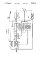
- FIG. 5 illustrates, in block diagram form, the LPCES encoder according to the present invention.
- the input signal is first analyzed in a linear predictive coding (LPC) analysis circuit 40.
- LPC linear predictive coding
- pre-emphasis coefficient is 0.85
- an input Hamming window an input Hamming window
- autocorrelation analysis autocorrelation analysis
- Durbin's Algorithm Durbin's Algorithm
- a codebook 42 is searched to produce a signal which is multiplied in a multiplier 43 by a gain factor to produce an excitation sequence input signal to LPC synthesis filter 41.
- the output signal of filter 41 is subtracted in a summer 45 from a speech samples input signal to produce an error signal that is supplied to an error minimizer 46.
- the output signal of error minimizer 46 is a codeword (CW) index that is fed back to codebook 42.
- the combination comprising LPC Synthesis filter 41, codebook 42, multiplier 43, summer 45, and error minimizer 46 constitute a codeword selector 53.
- Codebook 42 is comprised of vectors that are 120 samples long. It might typically contain sixteen vectors, fifteen derived from actual speech LPC residual sequences, with the remaining vector comprising a single impulse. Because the vectors are 120 samples long, the system is capable of accommodating speakers with pitch frequencies as low as 66.6 Hz, given an 8 kHz sampling rate.
- a new excitation codeword is chosen at the start of each frame, in synchronism with the output pitch period. Only the first P samples of the selected vector are used as excitation, with P indicating the fundamental (pitch) period of the input speech.
- the input signal is also supplied to an LPC inverse filter 47 which receives the LPC coefficient output signal from LPC analysis circuit 40.
- the output signal of the LPC inverse filter is supplied to a pitch detector 48 which generates both a pitch lag output signal and a pitch autocorrelation ( ⁇ ) output signal.
- LPC inverse filter 47 is a standard technique which requires no further description for those skilled in the art.
- Pitch detector 48 performs a standard autocorrelation function, but provides the first-order normalized autocorrelation of the pitch lag ( ⁇ ) as an output signal.
- the autocorrelation ⁇ also called the "pitch tap gain" is used in the voiced/unvoiced decision and in the decoder's codeword excited synthesizer.
- the input signal to pitch detector 48 from LPC inverse filter 47 should be lowpass filtered (800-1000 Hz cutoff frequency).
- the input speech signal and LPC residual speech signal (from filter 47) are supplied to a frame buffer 50.
- Buffer 50 stores the samples of these signals in two arrays (one for the input speech and one for the residual speech) for use by a pitch epoch position detector 49.
- the function of the pitch epoch position detector is to find the point where the maximum excitation of the speaker's vocal tract occurs over a pitch cycle. This point acts as a fixed reference within a pitch period that is used as an anchor in the codebook search process and is also used in the initial generation of the codebook entries.
- the anchor represents the definite point in time in the incoming speech to be matched against the first sample in each codeword.
- Epoch detector 49 is based on a peak picker operating on the stored input and residual speech signals in buffer 50.
- the algorithm works as follows: First, the maximum amplitude (absolute value) point in the input speech frame (location PMAX in ) is found. Second, a search is made between PMAX in and PMAX in -15 for an amplitude peak in the residual; this is PMAX res . PMAX res is used as a standard anchor point within a given frame.
- the output signal of frame buffer 50 is made up of segments of the input and residual speech signals beginning slightly before the standard anchor point and lasting for just over one pitch period. These input speech sample segments and residual speech sample segments, along with the pitch period (from pitch detecto 48), are provided to a gain estimator 51.
- the gain estimator calculates the gain of the speech input signal and of the LPC speech residual by computing the root-mean-square (RMS) energy for one pitch period of the input and residual speech signals, respectively.
- RMS root-mean-square
- the RMS residual speech gain from estimator 51 is applied to multiplier 43 in the codeword selector, while the input speech gain, the pitch and ⁇ signals from pitch detector 48, the LPC coefficients from LPC analysis circuit 40 and the CW index from error minimizer 46 are all applied to a multiplexer 52 for transmission to the channel.
- codeword selector 53 To understand how codeword selector 53 operates, consideration must first be given to how a codebook is constructed for the LPCES algorithm. To create a codebook, "typical" input speech segments are analyzed with the same pitch epoch detection technique given above to determine the PMAX res anchor point. Codewords are added to a prospective codebook by windowing out one pitch period of source speech material between the points located at PMAX rex -4 and PMAX res -4+P, where P is the pitch period. The P samples are placed in the first P locations of a codeword vector, with the remaining 120 -P locations filled with zeros. During actual operation of the LPCES coder, PMAX res is passed directly to the next stage of the algorithm. This stage selects the codeword to be used in the output synthesis.
- the codeword selector chooses the excitation vector to be used in the output signal of the LPC synthesizer. It accomplishes this by comparing one pitch period of the input speech in the vicinity of the PMAX res anchor point to one pitch period of the synthetic output speech corresponding to each codeword.
- the entire codebook is exhaustively searched for the filtered codeword comparing most favorably with the input signal.
- each codeword in the codebook must be run through LPC synthesis filter 41 for each frame that is processed. Although this operation is similar to what is required in the CELP coder, the computational operations for LPCES are about an order of magnitude less complex because (1) the codebook size for reasonable operation is only twelve to sixteen entries, and (2) only one pitch period per frame of synthesis filtering is required. In addition, the initial conditions in synthesis filter 41 must be set from the last pitch period of the last frame to ensure correct operation.
- a comparison operation is performed by aligning one pitch period of the codeword-excited synthetic output speech signal with one pitch period of the input speech near the anchor point.
- the mean-square difference between these two sequences is then computed for all codewords.
- the codeword producing the minimum mean-square difference (or MSE) is the one selected for output synthesis.
- MSE is computed at several different alignment positions near the PMAX res point.
- the LPCES voiced/unvoiced decision procedure is similar to that used in LPC-10 encoders, but includes an SNR (signal-to-noise ratio) criterion. Since some codewords might perform very well under unvoiced operation, they are allowed to be used if they result in a close match to the input speech. If SNR is the ratio of codeword RMSE (root-mean-square-error) to input RMS power, then the V/UV (voiced/unvoiced) decision is defined by the following pseudocode:
- ZCN is the normalized zero-crossing rate
- RMSIN is the input RMS level
- BETA is the pitch tap gain
- the codeword-excited LPC synthesizer is quite similar to the LPC-10 synthesizer, except that the codebook is used as an excitation source (instead of single impulses).
- the P samples of the selected codeword are repeatedly played out, creating a synthetic voiced output signal that has the correct fundamental frequency.
- the codeword selection is updated, or allowed to change, once per frame. Occasionally, the codeword selection algorithm may choose a word that causes an abrupt change in the excitation waveform at the end of a pitch period just after a frame boundary.
- the "correct" periodicity of the excitation waveform is ensured by forcing period-to-period changes in the excitation to occur no faster than the pitch tap gain would suggest.
- the excitation waveform e(i) is given by the following equation:
- the LPC coefficients are converted to reflection coefficients (or partial correlation coefficients, known as PARCORs) which are linearly quantized, with maximum amplitude limiting on RC(3)-RC(10) for better quantization acuity and artifact control during bit errors.
- RC reflection coefficient
- PARCORs partial correlation coefficients
- the RCs are quantized after the codeword selection algorithm is finished, to minimize unnecessary codeword switching.
- a switched differential encoding algorithm is used to provide up to three bits of extra acuity for all coefficients during sustained voiced phonemes.
- the other transmitted values are pitch period, filter gain, pitch tap gain, and codeword index.
- the bit allocations for all parameters are shown in the following table.
- the signal from the channel is applied to a demultiplexer 63 which separates the LPC coefficients, the gain, the pitch, the CW index, and the beta signals.
- the pitch and CW index signals are applied to a codebook 64 having sixteen entries.
- the output signal of codebook 64 is a codeword corresponding to the codeword selected in the encoder. This codeword is applied to a beta lock 65 which receives as its other input signal the ⁇ signal. Beta lock 65 enforces the correct periodicity in the excitation signal by employing the method of equation (1), above.
- the output signal of beta lock 65 and the gain signal are applied to a quadratic gain match circuit 66, the output signal of which, together with the LPC coefficients, is applied to an LPC synthesis filter 67 to generate the output speech.
- the filter state of LPC synthesis filter 67 is fed back to the quadratic gain match circuit to control that circuit.
- the quadratic gain match system 66 solves for the correct excitation scaling factor (gain) and applies it to the excitation signal.
- the output gain (G out ) can be estimated by solving the following quadratic equation:
- E z is the energy of the output signal due to the initial state in the synthesis filter (i.e., the energy of the zero-input response)
- C ze is the cross-correlation between the output signal due to the initial state in the filter and the output signal due to the excitation (or C ze may be defined as the correlation between the zero-input response and the zero-state response)
- E e is the energy due to the excitation only (i.e., the energy of the zero-state response)
- E i is the energy of the input signal (i.e., the transmitted gain for demultiplexer 63).
- the positive root (for G out ) of equation (2) is the output gain value.
- Application of the familiar quadratic equation formula is the preferred method for solution.
- the LPCES algorithm has been fully quantized at a rate of 4625 bits per second. It is implemented in floating point FORTRAN. Comparative measurements were made of the CPU (central processor unit) time required for LPC-10, LPCES and CELP. The results and test conditions are given below.
Abstract
Description
______________________________________
Voiced/Unvoiced.sub.-- Decision
IUV=0
IF ( ( (ZCN.GT.0.25)
          .AND. (RMSIN.LT.900.0)
          .AND. (BETA.LT.0.95)
          .AND. (SNR.LT.2.0) )
       .OR. (RMSIN.LT.50) ) IUV=1
______________________________________
e(i)=βe(i-P)+(1-β)code(i,index), (1)
 ______________________________________
LPC Coefficients     48       bits
Pitch                6        bits
Pitch Tap Gain       6        bits
Gain                 8        bits
Codeword Index (includes V/UV)
                     4        bits
Differential Quantization Selector
                     2        bits
Total                74       bits
Frame Rate (128 samples/frame)
                     62.5     frame/sec.
Output Rate          4625     bits/sec.
______________________________________
E.sub.z +2G.sub.out C.sub.ze +G.sup.2.sub.out E.sub.e =E.sub.i, (2)
______________________________________
CPU Time Test Conditions
______________________________________
LPC-10:   10-th order LPC model, ACF pitch detector
LPCES-14: 10-th order LPC model, 14 × (variable)
          codebook
CELP-16:  10-th order LPC model, 16 × 40 codebook,
          1 tap pitch predictor
CELP-1024:
          10-th order LPC model, 1024 × 40 codebook,
          1 tap pitch predictor
______________________________________
Normalized CPU Time to Process 1280 Samples
LPC-10 = 1 unit
LPC-10      LPCES-1    CELP-16    CELP-1024
______________________________________
1.0         4.4        13.2       102.3
______________________________________
Claims (6)
Priority Applications (1)
| Application Number | Priority Date | Filing Date | Title |
|---|---|---|---|
| US07/612,056 US5138661A (en) | 1990-11-13 | 1990-11-13 | Linear predictive codeword excited speech synthesizer |
Applications Claiming Priority (1)
| Application Number | Priority Date | Filing Date | Title |
|---|---|---|---|
| US07/612,056 US5138661A (en) | 1990-11-13 | 1990-11-13 | Linear predictive codeword excited speech synthesizer |
Publications (1)
| Publication Number | Publication Date |
|---|---|
| US5138661A true US5138661A (en) | 1992-08-11 |
Family
ID=24451530
Family Applications (1)
| Application Number | Title | Priority Date | Filing Date |
|---|---|---|---|
| US07/612,056 Expired - Lifetime US5138661A (en) | 1990-11-13 | 1990-11-13 | Linear predictive codeword excited speech synthesizer |
Country Status (1)
| Country | Link |
|---|---|
| US (1) | US5138661A (en) |
Cited By (36)
| Publication number | Priority date | Publication date | Assignee | Title |
|---|---|---|---|---|
| US5255343A (en) * | 1992-06-26 | 1993-10-19 | Northern Telecom Limited | Method for detecting and masking bad frames in coded speech signals |
| EP0627725A2 (en) * | 1993-05-28 | 1994-12-07 | Motorola, Inc. | Pitch period synchronous LPC-vocoder |
| WO1995016260A1 (en) * | 1993-12-07 | 1995-06-15 | Pacific Communication Sciences, Inc. | Adaptive speech coder having code excited linear prediction with multiple codebook searches |
| US5426718A (en) * | 1991-02-26 | 1995-06-20 | Nec Corporation | Speech signal coding using correlation valves between subframes |
| US5457783A (en) * | 1992-08-07 | 1995-10-10 | Pacific Communication Sciences, Inc. | Adaptive speech coder having code excited linear prediction |
| US5506899A (en) * | 1993-08-20 | 1996-04-09 | Sony Corporation | Voice suppressor |
| WO1996018186A1 (en) * | 1994-12-05 | 1996-06-13 | Motorola Inc. | Method and apparatus for synthesis of speech excitation waveforms |
| US5528727A (en) * | 1992-11-02 | 1996-06-18 | Hughes Electronics | Adaptive pitch pulse enhancer and method for use in a codebook excited linear predicton (Celp) search loop |
| US5577159A (en) * | 1992-10-09 | 1996-11-19 | At&T Corp. | Time-frequency interpolation with application to low rate speech coding |
| US5621853A (en) * | 1994-02-01 | 1997-04-15 | Gardner; William R. | Burst excited linear prediction |
| WO1997014139A1 (en) * | 1995-10-11 | 1997-04-17 | Philips Electronics N.V. | Signal prediction method and device for a speech coder |
| US5623575A (en) * | 1993-05-28 | 1997-04-22 | Motorola, Inc. | Excitation synchronous time encoding vocoder and method |
| US5657419A (en) * | 1993-12-20 | 1997-08-12 | Electronics And Telecommunications Research Institute | Method for processing speech signal in speech processing system |
| GB2312360A (en) * | 1996-04-12 | 1997-10-22 | Olympus Optical Co | Voice Signal Coding Apparatus |
| US5719994A (en) * | 1995-03-24 | 1998-02-17 | Sgs-Thomson Microelectronics S.A. | Determination of an excitation vector in CELP encoder |
| US5745871A (en) * | 1991-09-10 | 1998-04-28 | Lucent Technologies | Pitch period estimation for use with audio coders |
| US5752223A (en) * | 1994-11-22 | 1998-05-12 | Oki Electric Industry Co., Ltd. | Code-excited linear predictive coder and decoder with conversion filter for converting stochastic and impulsive excitation signals |
| WO1998027504A2 (en) * | 1996-12-06 | 1998-06-25 | Solana Technology Development Corporation | Method and apparatus for embedding auxiliary data in a primary data signal |
| KR19980025793A (en) * | 1996-10-05 | 1998-07-15 | 구자홍 | Voice data correction method and device |
| US5822360A (en) * | 1995-09-06 | 1998-10-13 | Solana Technology Development Corporation | Method and apparatus for transporting auxiliary data in audio signals |
| US5822721A (en) * | 1995-12-22 | 1998-10-13 | Iterated Systems, Inc. | Method and apparatus for fractal-excited linear predictive coding of digital signals |
| US5864797A (en) * | 1995-05-30 | 1999-01-26 | Sanyo Electric Co., Ltd. | Pitch-synchronous speech coding by applying multiple analysis to select and align a plurality of types of code vectors |
| US5913188A (en) * | 1994-09-26 | 1999-06-15 | Canon Kabushiki Kaisha | Apparatus and method for determining articulatory-orperation speech parameters |
| US6047253A (en) * | 1996-09-20 | 2000-04-04 | Sony Corporation | Method and apparatus for encoding/decoding voiced speech based on pitch intensity of input speech signal |
| WO2000022745A1 (en) * | 1998-10-09 | 2000-04-20 | Solana Technology Development Corporation | Method and apparatus for embedding auxiliary data in primary data signal using frequency and time domain processing |
| US6108624A (en) * | 1997-09-10 | 2000-08-22 | Samsung Electronics Co., Ltd. | Method for improving performance of a voice coder |
| US6125344A (en) * | 1997-03-28 | 2000-09-26 | Electronics And Telecommunications Research Institute | Pitch modification method by glottal closure interval extrapolation |
| US6192334B1 (en) * | 1997-04-04 | 2001-02-20 | Nec Corporation | Audio encoding apparatus and audio decoding apparatus for encoding in multiple stages a multi-pulse signal |
| US6272196B1 (en) * | 1996-02-15 | 2001-08-07 | U.S. Philips Corporaion | Encoder using an excitation sequence and a residual excitation sequence |
| US6415252B1 (en) * | 1998-05-28 | 2002-07-02 | Motorola, Inc. | Method and apparatus for coding and decoding speech |
| US20030083869A1 (en) * | 2001-08-14 | 2003-05-01 | Broadcom Corporation | Efficient excitation quantization in a noise feedback coding system using correlation techniques |
| US20070174054A1 (en) * | 2006-01-25 | 2007-07-26 | Mediatek Inc. | Communication apparatus with signal mode and voice mode |
| US20070255561A1 (en) * | 1998-09-18 | 2007-11-01 | Conexant Systems, Inc. | System for speech encoding having an adaptive encoding arrangement |
| US7454330B1 (en) * | 1995-10-26 | 2008-11-18 | Sony Corporation | Method and apparatus for speech encoding and decoding by sinusoidal analysis and waveform encoding with phase reproducibility |
| CN102201240A (en) * | 2011-05-27 | 2011-09-28 | 中国科学院自动化研究所 | Harmonic noise excitation model vocoder based on inverse filtering |
| US9263052B1 (en) * | 2013-01-25 | 2016-02-16 | Google Inc. | Simultaneous estimation of fundamental frequency, voicing state, and glottal closure instant |
Citations (8)
| Publication number | Priority date | Publication date | Assignee | Title |
|---|---|---|---|---|
| US4797926A (en) * | 1986-09-11 | 1989-01-10 | American Telephone And Telegraph Company, At&T Bell Laboratories | Digital speech vocoder |
| US4827517A (en) * | 1985-12-26 | 1989-05-02 | American Telephone And Telegraph Company, At&T Bell Laboratories | Digital speech processor using arbitrary excitation coding |
| US4868867A (en) * | 1987-04-06 | 1989-09-19 | Voicecraft Inc. | Vector excitation speech or audio coder for transmission or storage |
| US4873724A (en) * | 1986-07-17 | 1989-10-10 | Nec Corporation | Multi-pulse encoder including an inverse filter |
| US4980916A (en) * | 1989-10-26 | 1990-12-25 | General Electric Company | Method for improving speech quality in code excited linear predictive speech coding |
| US5060269A (en) * | 1989-05-18 | 1991-10-22 | General Electric Company | Hybrid switched multi-pulse/stochastic speech coding technique |
| US5067158A (en) * | 1985-06-11 | 1991-11-19 | Texas Instruments Incorporated | Linear predictive residual representation via non-iterative spectral reconstruction |
| US5073940A (en) * | 1989-11-24 | 1991-12-17 | General Electric Company | Method for protecting multi-pulse coders from fading and random pattern bit errors |
-
1990
- 1990-11-13 US US07/612,056 patent/US5138661A/en not_active Expired - Lifetime
Patent Citations (8)
| Publication number | Priority date | Publication date | Assignee | Title |
|---|---|---|---|---|
| US5067158A (en) * | 1985-06-11 | 1991-11-19 | Texas Instruments Incorporated | Linear predictive residual representation via non-iterative spectral reconstruction |
| US4827517A (en) * | 1985-12-26 | 1989-05-02 | American Telephone And Telegraph Company, At&T Bell Laboratories | Digital speech processor using arbitrary excitation coding |
| US4873724A (en) * | 1986-07-17 | 1989-10-10 | Nec Corporation | Multi-pulse encoder including an inverse filter |
| US4797926A (en) * | 1986-09-11 | 1989-01-10 | American Telephone And Telegraph Company, At&T Bell Laboratories | Digital speech vocoder |
| US4868867A (en) * | 1987-04-06 | 1989-09-19 | Voicecraft Inc. | Vector excitation speech or audio coder for transmission or storage |
| US5060269A (en) * | 1989-05-18 | 1991-10-22 | General Electric Company | Hybrid switched multi-pulse/stochastic speech coding technique |
| US4980916A (en) * | 1989-10-26 | 1990-12-25 | General Electric Company | Method for improving speech quality in code excited linear predictive speech coding |
| US5073940A (en) * | 1989-11-24 | 1991-12-17 | General Electric Company | Method for protecting multi-pulse coders from fading and random pattern bit errors |
Non-Patent Citations (8)
| Title |
|---|
| Atal et al., "A New Model of LPC Excitation for Producing Natural Sounding Speech at Low Bit Rates", Proc. of 1982 IEEE Int. Conf. on Acoustics, Speech and Signal Processing, May 1982, pp. 614-617. |
| Atal et al., A New Model of LPC Excitation for Producing Natural Sounding Speech at Low Bit Rates , Proc. of 1982 IEEE Int. Conf. on Acoustics, Speech and Signal Processing, May 1982, pp. 614 617. * |
| Markel et al., "A linear Prediction Vocoder Simulation Based Upon the Autocorrelation Method", IEEE Trans. on Acoustics, Speech, and Signal Processing, vol. ASSP-22, No. 2, Apr. 1974, pp. 124-134. |
| Markel et al., A linear Prediction Vocoder Simulation Based Upon the Autocorrelation Method , IEEE Trans. on Acoustics, Speech, and Signal Processing, vol. ASSP 22, No. 2, Apr. 1974, pp. 124 134. * |
| Schroeder et al., "High-Quality Speech at Very Low Bit Rates", Proc. of 1985 IEEE Int. Conf. on Acoustics, Speech and Signal Processing, Mar. 1985, pp. 937-940. |
| Schroeder et al., "Stochastic Coding of Speech Signals at Very Low Bit Rates", Proc of 1984 IEEE Int. Conf. on Communications, May 1984, pp. 1610-1613. |
| Schroeder et al., High Quality Speech at Very Low Bit Rates , Proc. of 1985 IEEE Int. Conf. on Acoustics, Speech and Signal Processing, Mar. 1985, pp. 937 940. * |
| Schroeder et al., Stochastic Coding of Speech Signals at Very Low Bit Rates , Proc of 1984 IEEE Int. Conf. on Communications, May 1984, pp. 1610 1613. * |
Cited By (60)
| Publication number | Priority date | Publication date | Assignee | Title |
|---|---|---|---|---|
| US5426718A (en) * | 1991-02-26 | 1995-06-20 | Nec Corporation | Speech signal coding using correlation valves between subframes |
| US5745871A (en) * | 1991-09-10 | 1998-04-28 | Lucent Technologies | Pitch period estimation for use with audio coders |
| US5255343A (en) * | 1992-06-26 | 1993-10-19 | Northern Telecom Limited | Method for detecting and masking bad frames in coded speech signals |
| US5457783A (en) * | 1992-08-07 | 1995-10-10 | Pacific Communication Sciences, Inc. | Adaptive speech coder having code excited linear prediction |
| US5577159A (en) * | 1992-10-09 | 1996-11-19 | At&T Corp. | Time-frequency interpolation with application to low rate speech coding |
| US5528727A (en) * | 1992-11-02 | 1996-06-18 | Hughes Electronics | Adaptive pitch pulse enhancer and method for use in a codebook excited linear predicton (Celp) search loop |
| US5504834A (en) * | 1993-05-28 | 1996-04-02 | Motrola, Inc. | Pitch epoch synchronous linear predictive coding vocoder and method |
| US5579437A (en) * | 1993-05-28 | 1996-11-26 | Motorola, Inc. | Pitch epoch synchronous linear predictive coding vocoder and method |
| EP0627725A3 (en) * | 1993-05-28 | 1997-01-29 | Motorola Inc | Pitch period synchronous LPC-vocoder. |
| EP0627725A2 (en) * | 1993-05-28 | 1994-12-07 | Motorola, Inc. | Pitch period synchronous LPC-vocoder |
| US5623575A (en) * | 1993-05-28 | 1997-04-22 | Motorola, Inc. | Excitation synchronous time encoding vocoder and method |
| US5506899A (en) * | 1993-08-20 | 1996-04-09 | Sony Corporation | Voice suppressor |
| WO1995016260A1 (en) * | 1993-12-07 | 1995-06-15 | Pacific Communication Sciences, Inc. | Adaptive speech coder having code excited linear prediction with multiple codebook searches |
| US5657419A (en) * | 1993-12-20 | 1997-08-12 | Electronics And Telecommunications Research Institute | Method for processing speech signal in speech processing system |
| US5621853A (en) * | 1994-02-01 | 1997-04-15 | Gardner; William R. | Burst excited linear prediction |
| US5913188A (en) * | 1994-09-26 | 1999-06-15 | Canon Kabushiki Kaisha | Apparatus and method for determining articulatory-orperation speech parameters |
| US6275795B1 (en) * | 1994-09-26 | 2001-08-14 | Canon Kabushiki Kaisha | Apparatus and method for normalizing an input speech signal |
| US5752223A (en) * | 1994-11-22 | 1998-05-12 | Oki Electric Industry Co., Ltd. | Code-excited linear predictive coder and decoder with conversion filter for converting stochastic and impulsive excitation signals |
| US5727125A (en) * | 1994-12-05 | 1998-03-10 | Motorola, Inc. | Method and apparatus for synthesis of speech excitation waveforms |
| WO1996018186A1 (en) * | 1994-12-05 | 1996-06-13 | Motorola Inc. | Method and apparatus for synthesis of speech excitation waveforms |
| US5719994A (en) * | 1995-03-24 | 1998-02-17 | Sgs-Thomson Microelectronics S.A. | Determination of an excitation vector in CELP encoder |
| US5864797A (en) * | 1995-05-30 | 1999-01-26 | Sanyo Electric Co., Ltd. | Pitch-synchronous speech coding by applying multiple analysis to select and align a plurality of types of code vectors |
| US5822360A (en) * | 1995-09-06 | 1998-10-13 | Solana Technology Development Corporation | Method and apparatus for transporting auxiliary data in audio signals |
| US6154484A (en) * | 1995-09-06 | 2000-11-28 | Solana Technology Development Corporation | Method and apparatus for embedding auxiliary data in a primary data signal using frequency and time domain processing |
| WO1997014139A1 (en) * | 1995-10-11 | 1997-04-17 | Philips Electronics N.V. | Signal prediction method and device for a speech coder |
| US7454330B1 (en) * | 1995-10-26 | 2008-11-18 | Sony Corporation | Method and apparatus for speech encoding and decoding by sinusoidal analysis and waveform encoding with phase reproducibility |
| US5822721A (en) * | 1995-12-22 | 1998-10-13 | Iterated Systems, Inc. | Method and apparatus for fractal-excited linear predictive coding of digital signals |
| US6608877B1 (en) * | 1996-02-15 | 2003-08-19 | Koninklijke Philips Electronics N.V. | Reduced complexity signal transmission system |
| US6272196B1 (en) * | 1996-02-15 | 2001-08-07 | U.S. Philips Corporaion | Encoder using an excitation sequence and a residual excitation sequence |
| GB2312360B (en) * | 1996-04-12 | 2001-01-24 | Olympus Optical Co | Voice signal coding apparatus |
| GB2312360A (en) * | 1996-04-12 | 1997-10-22 | Olympus Optical Co | Voice Signal Coding Apparatus |
| US6047253A (en) * | 1996-09-20 | 2000-04-04 | Sony Corporation | Method and apparatus for encoding/decoding voiced speech based on pitch intensity of input speech signal |
| KR19980025793A (en) * | 1996-10-05 | 1998-07-15 | 구자홍 | Voice data correction method and device |
| WO1998027504A2 (en) * | 1996-12-06 | 1998-06-25 | Solana Technology Development Corporation | Method and apparatus for embedding auxiliary data in a primary data signal |
| WO1998027504A3 (en) * | 1996-12-06 | 1998-09-03 | Solana Technology Dev Corp | Method and apparatus for embedding auxiliary data in a primary data signal |
| US6125344A (en) * | 1997-03-28 | 2000-09-26 | Electronics And Telecommunications Research Institute | Pitch modification method by glottal closure interval extrapolation |
| US6192334B1 (en) * | 1997-04-04 | 2001-02-20 | Nec Corporation | Audio encoding apparatus and audio decoding apparatus for encoding in multiple stages a multi-pulse signal |
| US6108624A (en) * | 1997-09-10 | 2000-08-22 | Samsung Electronics Co., Ltd. | Method for improving performance of a voice coder |
| US6415252B1 (en) * | 1998-05-28 | 2002-07-02 | Motorola, Inc. | Method and apparatus for coding and decoding speech |
| US20090024386A1 (en) * | 1998-09-18 | 2009-01-22 | Conexant Systems, Inc. | Multi-mode speech encoding system |
| US20080147384A1 (en) * | 1998-09-18 | 2008-06-19 | Conexant Systems, Inc. | Pitch determination for speech processing |
| US20090164210A1 (en) * | 1998-09-18 | 2009-06-25 | Minspeed Technologies, Inc. | Codebook sharing for LSF quantization |
| US9401156B2 (en) | 1998-09-18 | 2016-07-26 | Samsung Electronics Co., Ltd. | Adaptive tilt compensation for synthesized speech |
| US20090182558A1 (en) * | 1998-09-18 | 2009-07-16 | Minspeed Technologies, Inc. (Newport Beach, Ca) | Selection of scalar quantixation (SQ) and vector quantization (VQ) for speech coding |
| US9269365B2 (en) | 1998-09-18 | 2016-02-23 | Mindspeed Technologies, Inc. | Adaptive gain reduction for encoding a speech signal |
| US20080288246A1 (en) * | 1998-09-18 | 2008-11-20 | Conexant Systems, Inc. | Selection of preferential pitch value for speech processing |
| US20080294429A1 (en) * | 1998-09-18 | 2008-11-27 | Conexant Systems, Inc. | Adaptive tilt compensation for synthesized speech |
| US20080319740A1 (en) * | 1998-09-18 | 2008-12-25 | Mindspeed Technologies, Inc. | Adaptive gain reduction for encoding a speech signal |
| US9190066B2 (en) | 1998-09-18 | 2015-11-17 | Mindspeed Technologies, Inc. | Adaptive codebook gain control for speech coding |
| US8650028B2 (en) | 1998-09-18 | 2014-02-11 | Mindspeed Technologies, Inc. | Multi-mode speech encoding system for encoding a speech signal used for selection of one of the speech encoding modes including multiple speech encoding rates |
| US8635063B2 (en) | 1998-09-18 | 2014-01-21 | Wiav Solutions Llc | Codebook sharing for LSF quantization |
| US20070255561A1 (en) * | 1998-09-18 | 2007-11-01 | Conexant Systems, Inc. | System for speech encoding having an adaptive encoding arrangement |
| US8620647B2 (en) | 1998-09-18 | 2013-12-31 | Wiav Solutions Llc | Selection of scalar quantixation (SQ) and vector quantization (VQ) for speech coding |
| WO2000022745A1 (en) * | 1998-10-09 | 2000-04-20 | Solana Technology Development Corporation | Method and apparatus for embedding auxiliary data in primary data signal using frequency and time domain processing |
| US7110942B2 (en) * | 2001-08-14 | 2006-09-19 | Broadcom Corporation | Efficient excitation quantization in a noise feedback coding system using correlation techniques |
| US20030083869A1 (en) * | 2001-08-14 | 2003-05-01 | Broadcom Corporation | Efficient excitation quantization in a noise feedback coding system using correlation techniques |
| US20070174054A1 (en) * | 2006-01-25 | 2007-07-26 | Mediatek Inc. | Communication apparatus with signal mode and voice mode |
| CN102201240B (en) * | 2011-05-27 | 2012-10-03 | 中国科学院自动化研究所 | Harmonic noise excitation model vocoder based on inverse filtering |
| CN102201240A (en) * | 2011-05-27 | 2011-09-28 | 中国科学院自动化研究所 | Harmonic noise excitation model vocoder based on inverse filtering |
| US9263052B1 (en) * | 2013-01-25 | 2016-02-16 | Google Inc. | Simultaneous estimation of fundamental frequency, voicing state, and glottal closure instant |
Similar Documents
| Publication | Publication Date | Title |
|---|---|---|
| US5138661A (en) | Linear predictive codeword excited speech synthesizer | |
| US5127053A (en) | Low-complexity method for improving the performance of autocorrelation-based pitch detectors | |
| US5060269A (en) | Hybrid switched multi-pulse/stochastic speech coding technique | |
| KR100264863B1 (en) | Method for speech coding based on a celp model | |
| US5293449A (en) | Analysis-by-synthesis 2,4 kbps linear predictive speech codec | |
| US4980916A (en) | Method for improving speech quality in code excited linear predictive speech coding | |
| Spanias | Speech coding: A tutorial review | |
| EP0422232B1 (en) | Voice encoder | |
| US6141638A (en) | Method and apparatus for coding an information signal | |
| US5953697A (en) | Gain estimation scheme for LPC vocoders with a shape index based on signal envelopes | |
| Kleijn et al. | Generalized analysis-by-synthesis coding and its application to pitch prediction | |
| US6169970B1 (en) | Generalized analysis-by-synthesis speech coding method and apparatus | |
| US5839098A (en) | Speech coder methods and systems | |
| JP3308764B2 (en) | Audio coding device | |
| WO2000057401A1 (en) | Computation and quantization of voiced excitation pulse shapes in linear predictive coding of speech | |
| Tzeng | Analysis-by-synthesis linear predictive speech coding at 2.4 kbit/s | |
| Tandel et al. | Implementation of CELP CODER and to evaluate the performance in terms of bit rate, coding delay and quality of speech | |
| JP3174756B2 (en) | Sound source vector generating apparatus and sound source vector generating method | |
| Akamine et al. | CELP coding with an adaptive density pulse excitation model | |
| Lee et al. | On reducing computational complexity of codebook search in CELP coding | |
| Yang et al. | Pitch synchronous multi-band (PSMB) speech coding | |
| JP3276358B2 (en) | CELP-type speech coding apparatus and CELP-type speech coding method | |
| Tseng | An analysis-by-synthesis linear predictive model for narrowband speech coding | |
| JP3103108B2 (en) | Audio coding device | |
| Xiongwei et al. | A new excitation model for LPC vocoder at 2.4 kb/s |
Legal Events
| Date | Code | Title | Description |
|---|---|---|---|
| AS | Assignment |
Owner name: GENERAL ELECTRIC COMPANY, A CORP. OF NEW YORK Free format text: ASSIGNMENT OF ASSIGNORS INTEREST.;ASSIGNORS:ZINSER, RICHARD L.;KOCH, STEVEN R.;REEL/FRAME:005514/0360 Effective date: 19901106 |
|
| FEPP | Fee payment procedure |
Free format text: PAYOR NUMBER ASSIGNED (ORIGINAL EVENT CODE: ASPN); ENTITY STATUS OF PATENT OWNER: LARGE ENTITY |
|
| STCF | Information on status: patent grant |
Free format text: PATENTED CASE |
|
| AS | Assignment |
Owner name: MARTIN MARIETTA CORPORATION, MARYLAND Free format text: ASSIGNMENT OF ASSIGNORS INTEREST;ASSIGNOR:GENERAL ELECTRIC COMPANY;REEL/FRAME:007046/0736 Effective date: 19940322 |
|
| AS | Assignment |
Owner name: GENERAL ELECTRIC COMPANY, NEW YORK Free format text: ASSIGNMENT OF ASSIGNORS INTEREST;ASSIGNOR:MARTIN MARIETTA CORPORATION;REEL/FRAME:007308/0391 Effective date: 19950127 |
|
| FPAY | Fee payment |
Year of fee payment: 4 |
|
| AS | Assignment |
Owner name: LOCKHEED MARTIN CORPORATION, MARYLAND Free format text: ASSIGNMENT OF ASSIGNORS INTEREST;ASSIGNOR:MARTIN MARIETTA CORPORATION;REEL/FRAME:008628/0518 Effective date: 19960128 |
|
| FPAY | Fee payment |
Year of fee payment: 8 |
|
| FEPP | Fee payment procedure |
Free format text: PAYOR NUMBER ASSIGNED (ORIGINAL EVENT CODE: ASPN); ENTITY STATUS OF PATENT OWNER: LARGE ENTITY Free format text: PAYER NUMBER DE-ASSIGNED (ORIGINAL EVENT CODE: RMPN); ENTITY STATUS OF PATENT OWNER: LARGE ENTITY |
|
| FPAY | Fee payment |
Year of fee payment: 12 |
|
| REMI | Maintenance fee reminder mailed |