US5143389A - Wheeled support frame for a removable plastic container having closure and actuating device - Google Patents
Wheeled support frame for a removable plastic container having closure and actuating device Download PDFInfo
- Publication number
- US5143389A US5143389A US07/672,165 US67216591A US5143389A US 5143389 A US5143389 A US 5143389A US 67216591 A US67216591 A US 67216591A US 5143389 A US5143389 A US 5143389A
- Authority
- US
- United States
- Prior art keywords
- cover
- container
- pressure member
- combination according
- leg
- Prior art date
- Legal status (The legal status is an assumption and is not a legal conclusion. Google has not performed a legal analysis and makes no representation as to the accuracy of the status listed.)
- Expired - Lifetime
Links
Images

Classifications
-
- B—PERFORMING OPERATIONS; TRANSPORTING
- B65—CONVEYING; PACKING; STORING; HANDLING THIN OR FILAMENTARY MATERIAL
- B65F—GATHERING OR REMOVAL OF DOMESTIC OR LIKE REFUSE
- B65F1/00—Refuse receptacles; Accessories therefor
- B65F1/14—Other constructional features; Accessories
- B65F1/16—Lids or covers
- B65F1/1615—Lids or covers with means for locking, fastening or permanently closing thereof
-
- B—PERFORMING OPERATIONS; TRANSPORTING
- B65—CONVEYING; PACKING; STORING; HANDLING THIN OR FILAMENTARY MATERIAL
- B65F—GATHERING OR REMOVAL OF DOMESTIC OR LIKE REFUSE
- B65F1/00—Refuse receptacles; Accessories therefor
- B65F1/14—Other constructional features; Accessories
- B65F1/141—Supports, racks, stands, posts or the like for holding refuse receptacles
- B65F1/1421—Supports, racks, stands, posts or the like for holding refuse receptacles having means for operating lids or covers
Definitions
- the invention relates to a plastic container with a bottom and connecting continuously onto the edge thereof, a standing wall of random shape, on the upper edge portion of which can be placed a cover, the cover and the edge portion being provided with co-acting locking means.
- Such plastic containers are frequently used for receiving chemical waste which is to be burned together with the container. For this purpose it must, on the one hand, be possible for the user to remove the cover during filling of the container, while on the other, it must be locked during transport to the incineration location such that it cannot come loose.
- the container according to the invention is distinguished in that the upper edge is circular and that the locking means are formed on the one hand by a number of L-shaped locking members distributed uniformly over the periphery, one leg thereof being fixed to the cover or the edge portion of the container such that it is oriented perpendicularly to the bottom, and on the other hand by an outward pointing lip on the edge portion or the cover against which the other leg of the locking member can be placed.
- the cover is provided with a peripheral groove into which fits the edge portion of the container, the L-shaped locking members being arranged along the outer periphery of the cover groove.
- the container can include an outward pointing flange provided with through-holes, the number of which is equal to the number of locking members, such that a part of the peripheral flange forms the lip-like locking part.
- the peripheral flange can include a recess for receiving a nose-like member on the L-shaped locking member.
- the invention further relates to a device for actuating the cover for a waste container as described above.
- This device is characterized by a frame with support for supporting the container, a pressure element for co-action with the cover movable relative to the support, which pressure element is rotatable about an axis perpendicular to the support.
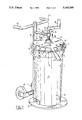
- FIG. 1 shows a perspective side view of a container arranged in an actuating device according to the invention
- FIGS. 2, 3 and 4 show respectively a side view of a detail of the locking means, a top view along the line III--III in FIG. 2 and a standing section along the line IV--IV in FIG. 2.
- the container according to the invention is designated with 1 and the cover with 2.
- the container has a bottom part 3 onto the edge of which connects the wall part 4, which is provided at the top with a circular edge 5.
- This latter is embodied inter alia with an outward pointing flange part 6, into which are recessed openings 7.
- the cover 2 is dish-shaped and the upstanding outer edge thereof has on the underside an annular groove 8, in the bottom of which is arranged a sealing element of resilient material 9.
- the edge part 5 of container 1 ends at the top in a zigzag-shaped edge strip 10, the top surface of which presses against the resilient material 9 when the cover is placed on the edge 5 of container 1.
- the outer peripheral portion of cover 2 is provided at regular mutual intervals with a locking member 12 which in the embodiment shown is L-shaped (see FIG. 2).
- a locking member 12 which in the embodiment shown is L-shaped (see FIG. 2).
- One leg 13 of the locking member points towards the bottom 3, while another leg 14 thereof has a length corresponding with the length of the through-hole 7 in the edge flange 6.
- This leg 14 co-acts with the bottom face of the edge flange 6, doing so along a limited lip-like portion 17 embodied on the underside with a recess 18.
- the leg 14 of the L-shaped locking member is embodied with a nose-like member 19 of a size such that it can fall into the recess 18, as shown in FIG. 2.
- FIG. 3 can be seen that the leg 14 is displaced slightly outward relative to the leg 13 in order to preserve a space 20 between the peripheral edge 11 of the cover 2 for the purpose of remaining free of the portion of the flange 6 lying adjacent to the edge strip 5 (see FIG. 4).
- FIG. 1 shows that a large number of L-shaped locking members 12 are utilized, this number corresponding with the number of through-holes 7 in flange 6.
- Each L-shaped locking member 12 can thus be placed through an opening 7 of flange 6 and locking can be effected by turning the cover 2 relative to the container 1, since all legs 14 of the locking members 12 come to lie against the underside of flange 6, wherein all nose-like members 19 can fall into a corresponding recess 18, thus permanently locking the cover 2 onto container 1.
- the locking is brought about, inter alia, because the resilient material 9 is temporarily compressed and springs back again as soon as the nose-like member 19 falls into the recess 18.
- a permanent sealing of the container content is nonetheless ensured so that the container 1 with a cover 2 arranged thereon is secure for transport of chemical or toxic material stored in the container 1.
- the container with cover can be incinerated in the combustion furnace together with the contents thereof.
- FIG. 1 An actuating device, which is shown schematically in FIG. 1.
- This device consists of a frame 30 provided at the bottom with a supporting plate 31 whereon the bottom 3 of container 1 can be placed.
- the bottom plate 31 is embodied with stops 32 which prevent a turning of the container 1 relative to the supporting plate 31 and also localize the container in the correct position.
- the frame 30 is further provided at an interval above the supporting plate 31 with a pressure member 33 in the form of a plate which can be moved in the direction towards and away from the support 31 with a moving mechanism 34 to be further designated below.
- the moving mechanism 34 consists of a fixed arm 35 attached to frame 30, which arm ends in a screw eye 36.
- a threaded spindle 37 provided at the top end with a crank 38 which can be operated manually.
- the threaded spindle 37 is embodied on the other side with a ball hinge 39 which is close-fittingly accommodated in a ball holder 40 of the pressure member 33.
- the plate-like pressure member 33 is embodied with a hand-grip 41 with which it is possible to turn the pressure member 33 round the spindle axis A-A standing perpendicularly of the supporting plate 31.
- the friction between the plate-like pressure member 33 and the cover 2 can transmit the turning onto the cover.
- the pressure member 33 can also be provided with recesses 42 into which fit stubs 43 forming an integral part of the upper rim of cover 2.
- the frame 30 is embodied with travel wheels 45 in addition to a handle 46 for easy transport of the container to a place of collection or use.
- outward pointing flange 6 on the outside of container 1 can be replaced by a number of lips which corresponds with the number of locking members 12 and which are arranged on the outside of the container 1 in a manner similar to a flange 6.
Abstract
Description
Claims (16)
Applications Claiming Priority (2)
| Application Number | Priority Date | Filing Date | Title |
|---|---|---|---|
| NL9000697A NL9000697A (en) | 1990-03-23 | 1990-03-23 | PLASTIC CONTAINER WITH CLOSING LID AND DEVICE FOR OPERATING THE SAME. |
| NL9000697 | 1990-03-23 |
Publications (1)
| Publication Number | Publication Date |
|---|---|
| US5143389A true US5143389A (en) | 1992-09-01 |
Family
ID=19856809
Family Applications (1)
| Application Number | Title | Priority Date | Filing Date |
|---|---|---|---|
| US07/672,165 Expired - Lifetime US5143389A (en) | 1990-03-23 | 1991-03-19 | Wheeled support frame for a removable plastic container having closure and actuating device |
Country Status (8)
| Country | Link |
|---|---|
| US (1) | US5143389A (en) |
| EP (1) | EP0454194B1 (en) |
| AT (1) | ATE130820T1 (en) |
| DE (1) | DE69114898T2 (en) |
| DK (1) | DK0454194T3 (en) |
| ES (1) | ES2080234T3 (en) |
| GR (1) | GR3018768T3 (en) |
| NL (1) | NL9000697A (en) |
Cited By (20)
| Publication number | Priority date | Publication date | Assignee | Title |
|---|---|---|---|---|
| US5515897A (en) * | 1993-06-17 | 1996-05-14 | Douglas Fehan | Golf bag travel cover |
| US5735427A (en) * | 1995-10-23 | 1998-04-07 | Russell-Stanley Corporation | Open top container |
| US5918756A (en) * | 1997-04-29 | 1999-07-06 | Morgan; H. William | Vessel lock down system |
| US6027128A (en) * | 1994-07-20 | 2000-02-22 | Premier Drywall Tool Co. | Multi-purpose dolly-truck |
| US20020158068A1 (en) * | 2001-04-30 | 2002-10-31 | Panek Robert Joseph | Medical waste disposal system |
| US6682084B2 (en) * | 2001-07-30 | 2004-01-27 | Vestil Manufacturing Company | Container dolly with multi-purpose handle |
| US20040129326A1 (en) * | 2003-01-03 | 2004-07-08 | Brian Smith | Guide plate |
| US20070069490A1 (en) * | 2005-09-23 | 2007-03-29 | John Japuntich | Sharps container configured for cart mounting |
| US20070068942A1 (en) * | 2005-09-26 | 2007-03-29 | Smudde Anton M | Multiple container cart with individual foot pedal/lid actuation |
| US7281720B1 (en) * | 2006-05-16 | 2007-10-16 | Richards Robert M | Drum transport cart |
| US20080088103A1 (en) * | 2006-10-13 | 2008-04-17 | Craig Sloat | Locking barrel caddie |
| US20090145901A1 (en) * | 2001-04-30 | 2009-06-11 | Cavidien Ag | Medical Waste Disposal System |
| US20100044379A1 (en) * | 2006-12-20 | 2010-02-25 | Filter Specialists, Inc. | Vessel lock down system |
| US8517204B1 (en) | 2011-03-31 | 2013-08-27 | Stephan J. Spanninger | Drip pan device for collecting leaks from water heater |
| US8540101B1 (en) * | 2011-11-23 | 2013-09-24 | Mark Blue | Filter housing with liftable lid |
| US8627976B2 (en) | 2011-08-01 | 2014-01-14 | Bemis Manufacturing Company | Cart with latch |
| US8857646B1 (en) | 2011-11-23 | 2014-10-14 | Mark Blue | Filter housing with liftable lid |
| US9010562B1 (en) * | 2012-03-08 | 2015-04-21 | Stewart C. Sparks | Magnetic trash can anchor |
| CN109592259A (en) * | 2019-01-25 | 2019-04-09 | 王庆强 | A kind of sealing mechanism of general practice sharp disposable container |
| US10321968B2 (en) | 2015-10-23 | 2019-06-18 | Medline Industries, Inc. | Sharps container |
Families Citing this family (3)
| Publication number | Priority date | Publication date | Assignee | Title |
|---|---|---|---|---|
| DE4321199C2 (en) * | 1992-09-08 | 1995-11-30 | Manfred Meul | Waste containers |
| DE9313381U1 (en) * | 1993-09-04 | 1993-11-04 | Sauerhoefer Dieter | Garbage can |
| CN103029936A (en) * | 2012-11-26 | 2013-04-10 | 山东点服软件有限公司 | Novel dustbin |
Citations (14)
| Publication number | Priority date | Publication date | Assignee | Title |
|---|---|---|---|---|
| US664555A (en) * | 1899-08-07 | 1900-12-25 | Frank E Jewett | Apparatus for securing barrels when steaming. |
| US1444125A (en) * | 1923-02-06 | Combinatiokt baeeel-tstrgk-emptying device | ||
| US1837411A (en) * | 1930-04-11 | 1931-12-22 | Edward S Cutter | Garbage can holder |
| US2079698A (en) * | 1936-12-08 | 1937-05-11 | Roesinger Herbert | Container lid |
| US2405674A (en) * | 1945-09-01 | 1946-08-13 | Adolph M Schliwa | Golf bag carrier |
| US2643044A (en) * | 1947-07-24 | 1953-06-23 | Our Savior S Evangelical Luthe | Grease gun loading pail base for grease containers with cutter and interlock means for said containers |
| US2667320A (en) * | 1952-11-01 | 1954-01-26 | Henry H Whitley | Garbage can cart |
| FR1504747A (en) * | 1966-10-19 | 1967-12-08 | Improvements to garbage boxes, bins or the like | |
| US3811597A (en) * | 1972-04-17 | 1974-05-21 | Continental Can Co | Plastic container |
| US3830514A (en) * | 1973-02-12 | 1974-08-20 | Greer H | Refuse container cart with improved lid-actuating handle |
| US4333580A (en) * | 1980-09-29 | 1982-06-08 | Associated Plastics, Inc. | Mechanism for locking two halves of an underground vault |
| US4723686A (en) * | 1986-12-17 | 1988-02-09 | Pennisi Ricky C | Trash can lid fastening means |
| EP0301467A2 (en) * | 1987-07-30 | 1989-02-01 | Jagtenberg Holding B.V. | Closable container for infectious refuse, body parts and organic refuse |
| FR2627168A1 (en) * | 1988-02-11 | 1989-08-18 | Siguier Daniel | Waste disposal bin - has moulded rim on receptacle with three fingers engaging with similar fingers on lid |
-
1990
- 1990-03-23 NL NL9000697A patent/NL9000697A/en not_active Application Discontinuation
-
1991
- 1991-03-19 AT AT91200608T patent/ATE130820T1/en not_active IP Right Cessation
- 1991-03-19 DK DK91200608.7T patent/DK0454194T3/en active
- 1991-03-19 US US07/672,165 patent/US5143389A/en not_active Expired - Lifetime
- 1991-03-19 DE DE69114898T patent/DE69114898T2/en not_active Expired - Fee Related
- 1991-03-19 ES ES91200608T patent/ES2080234T3/en not_active Expired - Lifetime
- 1991-03-19 EP EP91200608A patent/EP0454194B1/en not_active Expired - Lifetime
-
1996
- 1996-01-24 GR GR960400167T patent/GR3018768T3/en unknown
Patent Citations (14)
| Publication number | Priority date | Publication date | Assignee | Title |
|---|---|---|---|---|
| US1444125A (en) * | 1923-02-06 | Combinatiokt baeeel-tstrgk-emptying device | ||
| US664555A (en) * | 1899-08-07 | 1900-12-25 | Frank E Jewett | Apparatus for securing barrels when steaming. |
| US1837411A (en) * | 1930-04-11 | 1931-12-22 | Edward S Cutter | Garbage can holder |
| US2079698A (en) * | 1936-12-08 | 1937-05-11 | Roesinger Herbert | Container lid |
| US2405674A (en) * | 1945-09-01 | 1946-08-13 | Adolph M Schliwa | Golf bag carrier |
| US2643044A (en) * | 1947-07-24 | 1953-06-23 | Our Savior S Evangelical Luthe | Grease gun loading pail base for grease containers with cutter and interlock means for said containers |
| US2667320A (en) * | 1952-11-01 | 1954-01-26 | Henry H Whitley | Garbage can cart |
| FR1504747A (en) * | 1966-10-19 | 1967-12-08 | Improvements to garbage boxes, bins or the like | |
| US3811597A (en) * | 1972-04-17 | 1974-05-21 | Continental Can Co | Plastic container |
| US3830514A (en) * | 1973-02-12 | 1974-08-20 | Greer H | Refuse container cart with improved lid-actuating handle |
| US4333580A (en) * | 1980-09-29 | 1982-06-08 | Associated Plastics, Inc. | Mechanism for locking two halves of an underground vault |
| US4723686A (en) * | 1986-12-17 | 1988-02-09 | Pennisi Ricky C | Trash can lid fastening means |
| EP0301467A2 (en) * | 1987-07-30 | 1989-02-01 | Jagtenberg Holding B.V. | Closable container for infectious refuse, body parts and organic refuse |
| FR2627168A1 (en) * | 1988-02-11 | 1989-08-18 | Siguier Daniel | Waste disposal bin - has moulded rim on receptacle with three fingers engaging with similar fingers on lid |
Cited By (35)
| Publication number | Priority date | Publication date | Assignee | Title |
|---|---|---|---|---|
| US5515897A (en) * | 1993-06-17 | 1996-05-14 | Douglas Fehan | Golf bag travel cover |
| US6027128A (en) * | 1994-07-20 | 2000-02-22 | Premier Drywall Tool Co. | Multi-purpose dolly-truck |
| US5735427A (en) * | 1995-10-23 | 1998-04-07 | Russell-Stanley Corporation | Open top container |
| US5918756A (en) * | 1997-04-29 | 1999-07-06 | Morgan; H. William | Vessel lock down system |
| US20020158068A1 (en) * | 2001-04-30 | 2002-10-31 | Panek Robert Joseph | Medical waste disposal system |
| US8695834B2 (en) | 2001-04-30 | 2014-04-15 | Covidien Lp | Medical waste disposal container system |
| US20040222335A1 (en) * | 2001-04-30 | 2004-11-11 | Panek Robert Joseph | Medical waste disposal system |
| US20080156666A1 (en) * | 2001-04-30 | 2008-07-03 | Tyco Healthcare Group Lp | Medical Waste Disposal System |
| US7114629B2 (en) | 2001-04-30 | 2006-10-03 | Tyco Healthcare Group Lp | Medical waste disposal system |
| US8613366B2 (en) | 2001-04-30 | 2013-12-24 | Covidien Lp | Medical waste disposal system |
| US8201704B2 (en) | 2001-04-30 | 2012-06-19 | Brian Finnestad | Medical waste disposal system |
| US7784167B2 (en) | 2001-04-30 | 2010-08-31 | Tyco Healthcare Group Lp | Method of forming a medical waste disposal system |
| US20090145901A1 (en) * | 2001-04-30 | 2009-06-11 | Cavidien Ag | Medical Waste Disposal System |
| US7364049B2 (en) | 2001-04-30 | 2008-04-29 | Covidien Ag | Medical waste disposal system |
| US20080156818A1 (en) * | 2001-04-30 | 2008-07-03 | Tyco Healthcare Group Lp | Medical Waste Disposal Container System |
| US6682084B2 (en) * | 2001-07-30 | 2004-01-27 | Vestil Manufacturing Company | Container dolly with multi-purpose handle |
| US6851452B2 (en) * | 2003-01-03 | 2005-02-08 | General Signal Uk Limited | Guide plate |
| US20040129326A1 (en) * | 2003-01-03 | 2004-07-08 | Brian Smith | Guide plate |
| US20070069490A1 (en) * | 2005-09-23 | 2007-03-29 | John Japuntich | Sharps container configured for cart mounting |
| US7878358B2 (en) | 2005-09-26 | 2011-02-01 | Covidien Ag | Multiple container cart with individual foot pedal/lid actuation |
| US20070068942A1 (en) * | 2005-09-26 | 2007-03-29 | Smudde Anton M | Multiple container cart with individual foot pedal/lid actuation |
| US7281720B1 (en) * | 2006-05-16 | 2007-10-16 | Richards Robert M | Drum transport cart |
| US7963534B2 (en) * | 2006-10-13 | 2011-06-21 | Craig Sloat | Locking barrel caddie |
| US20080088103A1 (en) * | 2006-10-13 | 2008-04-17 | Craig Sloat | Locking barrel caddie |
| US20100044379A1 (en) * | 2006-12-20 | 2010-02-25 | Filter Specialists, Inc. | Vessel lock down system |
| US8083087B2 (en) | 2006-12-20 | 2011-12-27 | Filter Specialists, Inc. | Vessel lock down system |
| US8517204B1 (en) | 2011-03-31 | 2013-08-27 | Stephan J. Spanninger | Drip pan device for collecting leaks from water heater |
| US8627976B2 (en) | 2011-08-01 | 2014-01-14 | Bemis Manufacturing Company | Cart with latch |
| US8540101B1 (en) * | 2011-11-23 | 2013-09-24 | Mark Blue | Filter housing with liftable lid |
| US8857646B1 (en) | 2011-11-23 | 2014-10-14 | Mark Blue | Filter housing with liftable lid |
| US9010562B1 (en) * | 2012-03-08 | 2015-04-21 | Stewart C. Sparks | Magnetic trash can anchor |
| US10321968B2 (en) | 2015-10-23 | 2019-06-18 | Medline Industries, Inc. | Sharps container |
| US11559369B2 (en) | 2015-10-23 | 2023-01-24 | Medline Industries, Lp | Sharps container |
| CN109592259A (en) * | 2019-01-25 | 2019-04-09 | 王庆强 | A kind of sealing mechanism of general practice sharp disposable container |
| CN109592259B (en) * | 2019-01-25 | 2021-06-04 | 王庆强 | Sealing mechanism of general sharps box |
Also Published As
| Publication number | Publication date |
|---|---|
| ES2080234T3 (en) | 1996-02-01 |
| EP0454194A3 (en) | 1993-11-24 |
| DE69114898T2 (en) | 1996-04-18 |
| EP0454194B1 (en) | 1995-11-29 |
| GR3018768T3 (en) | 1996-04-30 |
| EP0454194A2 (en) | 1991-10-30 |
| DE69114898D1 (en) | 1996-01-11 |
| DK0454194T3 (en) | 1996-01-22 |
| ATE130820T1 (en) | 1995-12-15 |
| NL9000697A (en) | 1991-10-16 |
Similar Documents
| Publication | Publication Date | Title |
|---|---|---|
| US5143389A (en) | Wheeled support frame for a removable plastic container having closure and actuating device | |
| AU638662B2 (en) | Locking system for a waste receptacle | |
| US4723686A (en) | Trash can lid fastening means | |
| US4691840A (en) | Lid locking handle for waste container | |
| US4753367A (en) | Wastebasket and inner liner retainer | |
| US4361249A (en) | Beverage container lid | |
| CA2120866C (en) | Seal with vent | |
| US5072850A (en) | Receptacle for foodstuffs and the like | |
| US5139299A (en) | Compartmented trash receptacle and holder assembly | |
| US5803300A (en) | Trash container with bag holder | |
| IL86742A0 (en) | Resealable container closure | |
| US5085340A (en) | System for locking a waste receptacle | |
| CA2088535A1 (en) | Improved transportating ring | |
| TW265317B (en) | Container having a twist-locking cover | |
| US4150764A (en) | Foot operated container and closure device | |
| EP0080882B1 (en) | Waste disposal bin | |
| USD351906S (en) | Medical waste disposal container lid | |
| IT1227418B (en) | DEVICE FOR THE TOTAL EMPTYING OF LARGE-SIZED CONTAINERS FOR LOW-SLIDING INK. | |
| USRE30875E (en) | Foot operated container and closure device | |
| JPH02117354U (en) | ||
| GB2227159A (en) | An infant's drinking vessel | |
| IL101224A0 (en) | Stackable plugged barrel of synthetic material | |
| US2621829A (en) | Paint container attachment | |
| JPH0354674Y2 (en) | ||
| US2936095A (en) | Manually releasable closure for containers |
Legal Events
| Date | Code | Title | Description |
|---|---|---|---|
| AS | Assignment |
Owner name: WIVA VERPAKKINGEN B.V., SOUVEREINSTRAAT 1, 4903 RH Free format text: ASSIGNMENT OF ASSIGNORS INTEREST.;ASSIGNOR:JONKERS, GODEFRIDUS H. J.;REEL/FRAME:005645/0624 Effective date: 19910314 |
|
| STCF | Information on status: patent grant |
Free format text: PATENTED CASE |
|
| FEPP | Fee payment procedure |
Free format text: PAYOR NUMBER ASSIGNED (ORIGINAL EVENT CODE: ASPN); ENTITY STATUS OF PATENT OWNER: LARGE ENTITY Free format text: PAT HLDR NO LONGER CLAIMS SMALL ENT STAT AS SMALL BUSINESS (ORIGINAL EVENT CODE: LSM2); ENTITY STATUS OF PATENT OWNER: LARGE ENTITY |
|
| FPAY | Fee payment |
Year of fee payment: 4 |
|
| FPAY | Fee payment |
Year of fee payment: 8 |
|
| FPAY | Fee payment |
Year of fee payment: 12 |