US5146090A - Particle beam apparatus having an immersion lens arranged in an intermediate image of the beam - Google Patents
Particle beam apparatus having an immersion lens arranged in an intermediate image of the beam Download PDFInfo
- Publication number
- US5146090A US5146090A US07/691,238 US69123891A US5146090A US 5146090 A US5146090 A US 5146090A US 69123891 A US69123891 A US 69123891A US 5146090 A US5146090 A US 5146090A
- Authority
- US
- United States
- Prior art keywords
- lens
- particle beam
- immersion lens
- beam apparatus
- immersion
- Prior art date
- Legal status (The legal status is an assumption and is not a legal conclusion. Google has not performed a legal analysis and makes no representation as to the accuracy of the status listed.)
- Expired - Fee Related
Links
Images
Classifications
-
- H—ELECTRICITY
- H01—ELECTRIC ELEMENTS
- H01J—ELECTRIC DISCHARGE TUBES OR DISCHARGE LAMPS
- H01J37/00—Discharge tubes with provision for introducing objects or material to be exposed to the discharge, e.g. for the purpose of examination or processing thereof
- H01J37/26—Electron or ion microscopes; Electron or ion diffraction tubes
- H01J37/28—Electron or ion microscopes; Electron or ion diffraction tubes with scanning beams
-
- H—ELECTRICITY
- H01—ELECTRIC ELEMENTS
- H01J—ELECTRIC DISCHARGE TUBES OR DISCHARGE LAMPS
- H01J37/00—Discharge tubes with provision for introducing objects or material to be exposed to the discharge, e.g. for the purpose of examination or processing thereof
- H01J37/02—Details
- H01J37/04—Arrangements of electrodes and associated parts for generating or controlling the discharge, e.g. electron-optical arrangement, ion-optical arrangement
- H01J37/10—Lenses
- H01J37/12—Lenses electrostatic
Definitions
- the invention is directed to a particle beam apparatus and, in particular, to a particle beam apparatus having a particle beam generator, a first lens system for focusing the particle beam and a second lens system for imaging onto a specimen an intermediate image produced by the first lens system.
- High resolution scanning electron microscopes have become necessary instruments in all areas of development and manufacture of microelectronic and optoelectronic components in order to visually evaluate sub-micrometer structures, in order to identify deviations from rated patterns and in order to acquire and evaluate topographical parameters such as heights, widths or angles of inclination.
- Conventional scanning electron microscopes however, only achieve the required spatial resolution of fractions or a micrometer down to a few nanometers for small working distances and high accelerating voltages above approximately 20 kV. At these distances and voltages resist structures and integrated circuits are damaged by the high-energy electrons and non-conductive or poorly conductive specimens are charged.
- low-aberration condenser and objective lenses provided the possibility of designing scanning electron microscopes and electron beam measuring equipment that achieve the spatial resolution required for high-precision measurements even for low beam energies in the range of approximately 0.5 through 3 keV.
- the lenses disclosed for example, from U.S. Pat. Nos. 4,785,176, 4,831,266, and 4,728,790 or in Microelectronic Electronic Engineering, Vol. 7, Nos. 2 through 4 (1987) pages 163 through 172, an electrostatic regarding field overlaid on the focusing magnetic field to considerably reduce the lens aberrations given the same working distance is utilized.
- U.S. Pat. No. 4,896,036 discloses a scanning electron microscope wherein the aberrations of an electrostatic detector objective lens are reduced using a corrector composed of a number of multiple elements.
- An object of the present invention is to provide a particle beam apparatus, particularly a scanning electron microscope, of the type initially cited that has a high spatial resolution even for low beam energies.
- This object is inventively achieved by a particle beam apparatus having a means for accelerating the particles from a first to a higher, second energy arranged in the intermediate image.
- An advantage of the present invention is that the spatial resolution of a conventional scanning electron microscope can be noticeably improved for low beam energies and comparatively large working distances.
- the re-equipping for low-energy operation takes on a very simple format since only an additional tube electrode, a high-voltage power pack means as well as insulating mounts for arranging the tube electrode in the column of the scanning electron microscope are essentially required.
- a first electrostatic immersion lens is used as the means for accelerating the particles.
- the first immersion lens has an upper electrode and a lower electrode, whereby the upper electrode is at the potential of an anode of the particle beam generator.
- the upper and lower electrodes each respectively have the shape of a hollow cylinder arranged concentrically relative to the beam axis of the first and second lens systems.
- a beam-guiding tube is connected to the anode as the upper electrode of the first immersion lens.
- the second lens systems has an objective lens that generates a magnetic field that focuses the particles and has a second electrostatic immersion lens, whereby the second immersion lens is arranged such that the electrical retarding field thereof overlays on the focusing magnetic field.
- An upper electrode of the second immersion lens is at the potential of the lower electrode of the first immersion lens.
- the upper electrode of the second immersion lens has the shape of a hollow cylinder projecting into the objective lens.
- the lower electrode of the first immersion lens is identical to the upper electrode of the second immersion lens.
- the particle beam apparatus further has means for deflecting the particle beam onto the specimen, and means for modulating the intensity of the particle beam.
- the particle beam apparatus can also have means for documenting the secondary particles triggered on the specimen or back-scattered from the specimen.
- the first lens system can have one or two condenser lenses.
- the means for accelerating the particles, such as the upper electrode and lower electrode of the first immersion lens can be arranged in the last intermediate image preceding the objective lens.
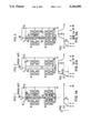
- FIGS. 1 and 2 schematically depict the structures of a conventional scanning electron microscope that is designed for low beam energies
- FIG. 1A depicts the shape of the ground-related potential V (z) for the FIG. 1 embodiment
- FIG. 2A depicts the shape of the potential V (z) for the FIG. 2 embodiment
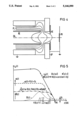
- FIG. 3 schematically depicts an exemplary embodiment of a scanning electron microscope of the present invention
- FIG. 3A depicts the shape of the potential V (z) for the FIG. 3 embodiment
- FIG. 4 depicts the distribution of electrical potential within the objective lens of the scanning electron microscope of the present invention.
- FIG. 5 is a graph showing the calculated electron paths r.sub. ⁇ (z) and r.sub. ⁇ * (z) within a purely magnetic or, respectively, an electrostatic-magnetic objective lens, the two paths intersect the optical axis OA (z-axis) in the specimen plane and have the same slope at that point.
- a conventional scanning electron microscope usually comprises an electron beam generator Q, a condenser unit KL composed of one or two pole piece lenses and an objective lens OL that images the intermediate image ZB of the virtual electron source that is produced by the condenser unit KL onto the specimen PR demagnified.
- the electron-optical column also contains a beam blanking system BBS, a deflection unit AS for positioning the electron beam on the specimen PR as well as a stigmator ST that corrects for astigmatism.
- the detectors (not shown) for documenting the secondary electrons triggered on the specimen PR and the primary electrons back-scattered from the specimen PR are usually arranged laterally below or, respectively, above the objective lens OL.
- An asymmetrical magnetic lens is used as objective lens OL, the pole pieces thereof concentrating the magnetic flux generated by the excitation coil onto a small spatial region around the optical axis OA (z-axis), whereby the magnetic field that is rotationally symmetrical around this axis OA reaches its maximum strength in the pole piece gap.
- the elementary charge is referenced e and the difference in potential built up between the cathode K and the anode A is referenced U 1 .
- the spatial resolution that is proportional to the beam diameter d on the specimen PR is essentially limited by the electron-to-electron interaction (Boersch effect) that opposes the focusing and by the axial chromatic aberration of the objective lens OL.
- the beam diameter d is approximately calculated as
- d C is the geometrical-optical probe diameter expanded by the Coulomb repulsion of the electrons in the beam path between the cathode K and the specimen PR (lateral Boersch effect) and d F is the diameter of the circle of least confusion produced by the chromatic aberration of the objective lens OL.
- the chromatic aberration constant C F is proportional to the focal distance f of the lens, the beam diameter d and, thus, the spatial resolution can be improved by reducing the focal distance. Narrow limits are placed on this, however, since the specimen PR must then be arranged extremely close and below the objective lens OL, i.e. in the magnetic field thereof. Moreover, larger specimens can then no longer be scanned in an inclined orientation. A further improvement in the spatial resolution is therefore only possible by a reduction of the Boersch effect (suppression of the energetic Boersch effect that influences the energy width e ⁇ U and of the lateral Boersch effect that effects an expansion of the beam) and by a reduction of the aberrations of the imaging system.
- the objective lens has noticeably smaller chromatic aberration and spherical aberration constants than does the purely magnetic objective lens of the scanning electron microscope of FIG. 1.
- the electrode AE that is under the objective lens OL and that is also at ground potential serves the purpose of shielding the specimen PR.
- the beam-guiding tube SR lies at a high voltage U 2 (see FIG. 2A that also shows the curve of potential V(z) referenced to apparatus ground or, respectively, the curve of potential ⁇ (z) referenced to the cathode on the beam axis and the position of the end of the beam tube), considerable modifications of the SEM electronics, particularly of the components for driving the beam blanking system that is also charged with the accelerating potential, are required in this scanning electron microscope.
- the present invention provides that an electrostatic immersion lens be arranged at the location of the intermediate image ZB generated by the condenser unit KL.
- the position of this last intermediate image ZB preceding the objective lens OL is usually retained with a double condenser.
- the objective lens OL has extremely low chromatic aberration and spherical aberration constants.
- the retarding field is thereby generated by means of the immersion lens formed of the tube electrode RE and the lower pole piece UP that is at ground potential (see FIG. 4).
- a shielding electrode AE is again provided under the objective lens OL in order to prevent the passage of the retarding field, indicated by potential lines PL in FIG. 4, onto the specimen PR.
- the immersion lens that generates the retarding field can be equivalently subdivided into a defocusing and a focusing part and since these are preferably arranged in the beam path following the magnetic lens, the electrons are first deflected in the magnetic field in the direction of the optical axis (z-axis) and are slightly refracted away from the optical axis in the defocusing part, in order to be subsequently focused onto the axis by the convergent electrostatic part.
- the quantity r.sub. ⁇ * (z) is always smaller than r.sub. ⁇ (z) in the purely magnetic lens, so that the aberration integrals for the chromatic aberration and spherical aberration constants are also correspondingly smaller.
- the present invention is not limited to the exemplary embodiments that have been set forth.
Abstract
Description
d=(d.sub.C.sup.2 +d.sub.F.sup.2).sup.1/2 (1)
d.sub.F =C.sub.F αΔU/U.sub.1 (2)
Claims (19)
Applications Claiming Priority (2)
| Application Number | Priority Date | Filing Date | Title |
|---|---|---|---|
| DE4018690 | 1990-06-11 | ||
| DE4018690 | 1990-06-11 |
Publications (1)
| Publication Number | Publication Date |
|---|---|
| US5146090A true US5146090A (en) | 1992-09-08 |
Family
ID=6408204
Family Applications (1)
| Application Number | Title | Priority Date | Filing Date |
|---|---|---|---|
| US07/691,238 Expired - Fee Related US5146090A (en) | 1990-06-11 | 1991-04-25 | Particle beam apparatus having an immersion lens arranged in an intermediate image of the beam |
Country Status (4)
| Country | Link |
|---|---|
| US (1) | US5146090A (en) |
| EP (1) | EP0461442B1 (en) |
| JP (1) | JP3268583B2 (en) |
| DE (1) | DE59108193D1 (en) |
Cited By (20)
| Publication number | Priority date | Publication date | Assignee | Title |
|---|---|---|---|---|
| US5371371A (en) * | 1992-08-27 | 1994-12-06 | Kabushiki Kaisha Toshiba | Magnetic immersion field emission electron gun systems capable of reducing aberration of electrostatic lens |
| US5424541A (en) * | 1992-03-19 | 1995-06-13 | Hitachi, Ltd. | Scanning electron microscope and method for controlling a scanning electron microscope |
| US5606261A (en) * | 1994-10-25 | 1997-02-25 | International Business Machines, Corporation | Retarding field electron-optical apparatus |
| EP0769799A2 (en) * | 1995-10-19 | 1997-04-23 | Hitachi, Ltd. | Scanning electron microscope |
| EP0893816A2 (en) * | 1997-07-25 | 1999-01-27 | LEO Elektronenmikroskopie GmbH | Corpuscular beam apparatus |
| US6069363A (en) * | 1998-02-26 | 2000-05-30 | International Business Machines Corporation | Magnetic-electrostatic symmetric doublet projection lens |
| US6407387B1 (en) * | 1998-11-30 | 2002-06-18 | Advantest Corp. | Particle beam apparatus |
| US6444981B1 (en) * | 1998-10-29 | 2002-09-03 | Hitachi, Ltd. | Scanning electron microscope |
| US6486471B1 (en) * | 1998-05-19 | 2002-11-26 | Seiko Instruments Inc. | Composite charge particle beam apparatus |
| US6822245B2 (en) * | 2000-07-18 | 2004-11-23 | Hitachi, Ltd. | Ion beam apparatus and sample processing method |
| US20050006582A1 (en) * | 2003-04-17 | 2005-01-13 | Leo Elektronenmikroskopie Gmbh | Electron microscopy system, electron microscopy method and focusing system for charged particles |
| US20050092922A1 (en) * | 2000-07-18 | 2005-05-05 | Hiroyuki Muto | Ion beam apparatus and sample processing method |
| US20050211898A1 (en) * | 2002-03-29 | 2005-09-29 | Cameca | Device for measuring the emission of x rays produced by an object exposed to an electron beam |
| US20060226361A1 (en) * | 2005-03-17 | 2006-10-12 | Juergen Frosien | Analyzing system and charged particle beam device |
| US20080310704A1 (en) * | 2007-06-18 | 2008-12-18 | Hitachi High-Technologies Corporation | Scanning electron microscope and method of imaging an object by using the scanning electron microscope |
| CN106165054A (en) * | 2014-04-28 | 2016-11-23 | 株式会社日立高新技术 | Electronic wire device |
| EP1489641B1 (en) * | 2003-06-18 | 2019-08-14 | ICT Integrated Circuit Testing Gesellschaft für Halbleiterprüftechnik mbH | Charged particle deflecting system |
| US10504684B1 (en) * | 2018-07-12 | 2019-12-10 | ICT Integrated Circuit Testing Gesellschaft für Halbleiterprüftechnik mbH | High performance inspection scanning electron microscope device and method of operating the same |
| US10777382B2 (en) | 2017-11-21 | 2020-09-15 | Focus-Ebeam Technology (Beijing) Co., Ltd. | Low voltage scanning electron microscope and method for specimen observation |
| US11823861B2 (en) | 2019-07-02 | 2023-11-21 | Hitachi High-Tech Corporation | Charged particle beam device |
Families Citing this family (9)
| Publication number | Priority date | Publication date | Assignee | Title |
|---|---|---|---|---|
| JP3774953B2 (en) * | 1995-10-19 | 2006-05-17 | 株式会社日立製作所 | Scanning electron microscope |
| JP3966350B2 (en) * | 1995-10-19 | 2007-08-29 | 株式会社日立製作所 | Scanning electron microscope |
| JP4179390B2 (en) * | 1995-10-19 | 2008-11-12 | 株式会社日立製作所 | Scanning electron microscope |
| JP4179369B2 (en) * | 1995-10-19 | 2008-11-12 | 株式会社日立製作所 | Scanning electron microscope |
| US6930709B1 (en) | 1997-12-04 | 2005-08-16 | Pentax Of America, Inc. | Integrated internet/intranet camera |
| DE10233002B4 (en) * | 2002-07-19 | 2006-05-04 | Leo Elektronenmikroskopie Gmbh | Objective lens for an electron microscopy system and electron microscopy system |
| NL1026006C2 (en) * | 2004-04-22 | 2005-10-25 | Fei Co | Particle-optical device provided with lenses with permanent magnetic material. |
| JP5230148B2 (en) * | 2007-09-04 | 2013-07-10 | キヤノン株式会社 | Charged particle beam drawing apparatus and device manufacturing method |
| US9595417B2 (en) * | 2014-12-22 | 2017-03-14 | ICT Integrated Circuit Testing Gesellschaft für Halbleiterprüftechnik mbH | High resolution charged particle beam device and method of operating the same |
Citations (7)
| Publication number | Priority date | Publication date | Assignee | Title |
|---|---|---|---|---|
| US4675524A (en) * | 1985-03-11 | 1987-06-23 | Siemens Aktiengesellschaft | Scanning particle microscope with diminished boersch effect |
| US4713543A (en) * | 1984-08-13 | 1987-12-15 | Siemens Aktiengesellschaft | Scanning particle microscope |
| US4728790A (en) * | 1985-06-14 | 1988-03-01 | Siemens Aktiengesellschaft | Low-abberation spectrometer objective with high secondary electron acceptance |
| US4766314A (en) * | 1985-06-22 | 1988-08-23 | Finnigan Mat Gmbh | Lens arrangement for the focusing of electrically charged particles, and mass spectrometer with such a lens arrangement |
| US4785176A (en) * | 1986-04-24 | 1988-11-15 | Siemens Aktiengesellschaft | Electrostatic-magnetic lens for particle beam apparatus |
| US4831266A (en) * | 1986-12-12 | 1989-05-16 | Siemens Aktiengesellschaft | Detector objective for particle beam apparatus |
| US4896036A (en) * | 1987-02-02 | 1990-01-23 | Siemens Aktiengesellschaft | Detector objective for scanning microscopes |
-
1991
- 1991-04-25 US US07/691,238 patent/US5146090A/en not_active Expired - Fee Related
- 1991-05-23 EP EP91108372A patent/EP0461442B1/en not_active Expired - Lifetime
- 1991-05-23 DE DE59108193T patent/DE59108193D1/en not_active Expired - Fee Related
- 1991-06-07 JP JP16394091A patent/JP3268583B2/en not_active Expired - Fee Related
Patent Citations (7)
| Publication number | Priority date | Publication date | Assignee | Title |
|---|---|---|---|---|
| US4713543A (en) * | 1984-08-13 | 1987-12-15 | Siemens Aktiengesellschaft | Scanning particle microscope |
| US4675524A (en) * | 1985-03-11 | 1987-06-23 | Siemens Aktiengesellschaft | Scanning particle microscope with diminished boersch effect |
| US4728790A (en) * | 1985-06-14 | 1988-03-01 | Siemens Aktiengesellschaft | Low-abberation spectrometer objective with high secondary electron acceptance |
| US4766314A (en) * | 1985-06-22 | 1988-08-23 | Finnigan Mat Gmbh | Lens arrangement for the focusing of electrically charged particles, and mass spectrometer with such a lens arrangement |
| US4785176A (en) * | 1986-04-24 | 1988-11-15 | Siemens Aktiengesellschaft | Electrostatic-magnetic lens for particle beam apparatus |
| US4831266A (en) * | 1986-12-12 | 1989-05-16 | Siemens Aktiengesellschaft | Detector objective for particle beam apparatus |
| US4896036A (en) * | 1987-02-02 | 1990-01-23 | Siemens Aktiengesellschaft | Detector objective for scanning microscopes |
Non-Patent Citations (2)
| Title |
|---|
| "High Performance Electron Optical Column for Testing ICs with Submicrometer Design Rules" by Erich Plies, Microelectronic Eng. 7, 1987, pp. 163-172. |
| High Performance Electron Optical Column for Testing ICs with Submicrometer Design Rules by Erich Plies, Microelectronic Eng. 7, 1987, pp. 163 172. * |
Cited By (35)
| Publication number | Priority date | Publication date | Assignee | Title |
|---|---|---|---|---|
| US5424541A (en) * | 1992-03-19 | 1995-06-13 | Hitachi, Ltd. | Scanning electron microscope and method for controlling a scanning electron microscope |
| US5371371A (en) * | 1992-08-27 | 1994-12-06 | Kabushiki Kaisha Toshiba | Magnetic immersion field emission electron gun systems capable of reducing aberration of electrostatic lens |
| US5606261A (en) * | 1994-10-25 | 1997-02-25 | International Business Machines, Corporation | Retarding field electron-optical apparatus |
| US5614833A (en) * | 1994-10-25 | 1997-03-25 | International Business Machines Corporation | Objective lens with large field deflection system and homogeneous large area secondary electron extraction field |
| EP0769799A2 (en) * | 1995-10-19 | 1997-04-23 | Hitachi, Ltd. | Scanning electron microscope |
| EP0769799A3 (en) * | 1995-10-19 | 2004-11-24 | Hitachi, Ltd. | Scanning electron microscope |
| EP0893816A3 (en) * | 1997-07-25 | 2003-01-29 | LEO Elektronenmikroskopie GmbH | Corpuscular beam apparatus |
| EP0893816A2 (en) * | 1997-07-25 | 1999-01-27 | LEO Elektronenmikroskopie GmbH | Corpuscular beam apparatus |
| US6194729B1 (en) * | 1997-07-25 | 2001-02-27 | Leo Elektronenmikroskopie Gmbh | Particle beam apparatus |
| US6069363A (en) * | 1998-02-26 | 2000-05-30 | International Business Machines Corporation | Magnetic-electrostatic symmetric doublet projection lens |
| US6486471B1 (en) * | 1998-05-19 | 2002-11-26 | Seiko Instruments Inc. | Composite charge particle beam apparatus |
| US6512228B2 (en) * | 1998-10-29 | 2003-01-28 | Hitachi, Ltd. | Scanning electron microscope |
| US6444981B1 (en) * | 1998-10-29 | 2002-09-03 | Hitachi, Ltd. | Scanning electron microscope |
| US6407387B1 (en) * | 1998-11-30 | 2002-06-18 | Advantest Corp. | Particle beam apparatus |
| US20050092922A1 (en) * | 2000-07-18 | 2005-05-05 | Hiroyuki Muto | Ion beam apparatus and sample processing method |
| US6822245B2 (en) * | 2000-07-18 | 2004-11-23 | Hitachi, Ltd. | Ion beam apparatus and sample processing method |
| US7084399B2 (en) | 2000-07-18 | 2006-08-01 | Hitachi, Ltd. | Ion beam apparatus and sample processing method |
| US20050211898A1 (en) * | 2002-03-29 | 2005-09-29 | Cameca | Device for measuring the emission of x rays produced by an object exposed to an electron beam |
| US6949744B2 (en) | 2003-04-17 | 2005-09-27 | Carl Zeiss Nts Gmbh | Electron microscopy system, electron microscopy method and focusing system for charged particles |
| US20050006582A1 (en) * | 2003-04-17 | 2005-01-13 | Leo Elektronenmikroskopie Gmbh | Electron microscopy system, electron microscopy method and focusing system for charged particles |
| EP1489641B1 (en) * | 2003-06-18 | 2019-08-14 | ICT Integrated Circuit Testing Gesellschaft für Halbleiterprüftechnik mbH | Charged particle deflecting system |
| US20060226361A1 (en) * | 2005-03-17 | 2006-10-12 | Juergen Frosien | Analyzing system and charged particle beam device |
| US7439500B2 (en) * | 2005-03-17 | 2008-10-21 | Ict Integrated Circuit Testing Gesellschaft Fur Halbleiterpruftechnik Mbh | Analyzing system and charged particle beam device |
| US20080310704A1 (en) * | 2007-06-18 | 2008-12-18 | Hitachi High-Technologies Corporation | Scanning electron microscope and method of imaging an object by using the scanning electron microscope |
| US7888640B2 (en) | 2007-06-18 | 2011-02-15 | Hitachi High-Technologies Corporation | Scanning electron microscope and method of imaging an object by using the scanning electron microscope |
| US20110095184A1 (en) * | 2007-06-18 | 2011-04-28 | Hitachi High-Technologies Corporation | Scanning electron microscope and method of imaging an object by using the scanning electron microscope |
| US8222601B2 (en) | 2007-06-18 | 2012-07-17 | Hitachi High Technologies Corporation | Scanning electron microscope and method of imaging an object by using the scanning electron microscope |
| US9966218B2 (en) * | 2014-04-28 | 2018-05-08 | Hitachi High-Technologies Corporation | Electron beam device |
| US20170040139A1 (en) * | 2014-04-28 | 2017-02-09 | Hitachi High-Technologies Corporation | Electron Beam Device |
| CN106165054B (en) * | 2014-04-28 | 2018-08-28 | 株式会社日立高新技术 | Electronic wire device |
| CN106165054A (en) * | 2014-04-28 | 2016-11-23 | 株式会社日立高新技术 | Electronic wire device |
| US10777382B2 (en) | 2017-11-21 | 2020-09-15 | Focus-Ebeam Technology (Beijing) Co., Ltd. | Low voltage scanning electron microscope and method for specimen observation |
| US11075056B2 (en) * | 2017-11-21 | 2021-07-27 | Focus-Ebeam Technology (Beijing) Co., Ltd. | Scanning electron microscope objective lens system and method for specimen observation |
| US10504684B1 (en) * | 2018-07-12 | 2019-12-10 | ICT Integrated Circuit Testing Gesellschaft für Halbleiterprüftechnik mbH | High performance inspection scanning electron microscope device and method of operating the same |
| US11823861B2 (en) | 2019-07-02 | 2023-11-21 | Hitachi High-Tech Corporation | Charged particle beam device |
Also Published As
| Publication number | Publication date |
|---|---|
| EP0461442A2 (en) | 1991-12-18 |
| DE59108193D1 (en) | 1996-10-24 |
| EP0461442B1 (en) | 1996-09-18 |
| JP3268583B2 (en) | 2002-03-25 |
| JPH0536371A (en) | 1993-02-12 |
| EP0461442A3 (en) | 1992-03-04 |
Similar Documents
| Publication | Publication Date | Title |
|---|---|---|
| US5146090A (en) | Particle beam apparatus having an immersion lens arranged in an intermediate image of the beam | |
| EP1045425B1 (en) | Charged particle beam column with chromatic aberration compensation | |
| US6218664B1 (en) | SEM provided with an electrostatic objective and an electrical scanning device | |
| US4785176A (en) | Electrostatic-magnetic lens for particle beam apparatus | |
| JP2789094B2 (en) | Detector objective lens for particle beam equipment | |
| US7915584B2 (en) | TEM with aberration corrector and phase plate | |
| US8319192B2 (en) | Charged particle apparatus | |
| US8841630B2 (en) | Corrector for axial aberrations of a particle-optical lens | |
| US4896036A (en) | Detector objective for scanning microscopes | |
| US5986269A (en) | Correction device for correcting chromatic aberration in particle-optical apparatus | |
| US6246058B1 (en) | Correction device for correcting chromatic aberration in particle-optical apparatus | |
| US9443692B2 (en) | Focused ion beam low kV enhancement | |
| US6897442B2 (en) | Objective lens arrangement for use in a charged particle beam column | |
| JP5439498B2 (en) | electronic microscope | |
| EP0150089A1 (en) | Charged-particle optical systems | |
| US20110139978A1 (en) | Charged particle beam device, method of operating a charged particle beam device | |
| Khursheed | Recent developments in scanning electron microscope design |
Legal Events
| Date | Code | Title | Description |
|---|---|---|---|
| AS | Assignment |
Owner name: SIEMENS AKTIENGESELLSCHAFT, MUNICH A GERMAN CORP. Free format text: ASSIGNMENT OF ASSIGNORS INTEREST.;ASSIGNOR:PLIES, ERICH;REEL/FRAME:005685/0918 Effective date: 19910417 |
|
| FEPP | Fee payment procedure |
Free format text: PAT HOLDER CLAIMS SMALL ENTITY STATUS - SMALL BUSINESS (ORIGINAL EVENT CODE: SM02); ENTITY STATUS OF PATENT OWNER: SMALL ENTITY |
|
| AS | Assignment |
Owner name: ICT INTEGRATED CIRCUIT TESTING, GESELLSCHAFT FUR, Free format text: ASSIGNMENT OF ASSIGNORS INTEREST;ASSIGNOR:SIEMENS AKTIENGESELLSCHAFT;REEL/FRAME:007541/0130 Effective date: 19941017 |
|
| FPAY | Fee payment |
Year of fee payment: 4 |
|
| REMI | Maintenance fee reminder mailed | ||
| AS | Assignment |
Owner name: APPLIED MATERIALS, INC., CALIFORNIA Free format text: ASSIGNMENT OF ASSIGNORS INTEREST;ASSIGNOR:ORBOT INSTRUMENTS, LIMITED;REEL/FRAME:010871/0492 Effective date: 20000512 |
|
| AS | Assignment |
Owner name: APPLIED MATERIALS, INC., CALIFORNIA Free format text: ASSIGNMENT OF ASSIGNORS INTEREST;ASSIGNOR:ORBOT INSTRUMENTS, LIMITED;REEL/FRAME:010927/0157 Effective date: 20000512 |
|
| LAPS | Lapse for failure to pay maintenance fees | ||
| FP | Lapsed due to failure to pay maintenance fee |
Effective date: 20000908 |
|
| AS | Assignment |
Owner name: APPLIED MATERIALS, INC., CALIFORNIA Free format text: CORRECTIVE ASSIGNMENT TO CORRECT THE ASSIGNMENT, PREVIOUSLY RECORDED AT REEL 10871 FRAME 0492;ASSIGNOR:ORBOT INSTRUMENTS, LIMITED;REEL/FRAME:012036/0461 Effective date: 20000512 |
|
| STCH | Information on status: patent discontinuation |
Free format text: PATENT EXPIRED DUE TO NONPAYMENT OF MAINTENANCE FEES UNDER 37 CFR 1.362 |