US5146276A - Rotatable focusing means and variable magnification electrophotocopier - Google Patents
Rotatable focusing means and variable magnification electrophotocopier Download PDFInfo
- Publication number
- US5146276A US5146276A US07/122,530 US12253087A US5146276A US 5146276 A US5146276 A US 5146276A US 12253087 A US12253087 A US 12253087A US 5146276 A US5146276 A US 5146276A
- Authority
- US
- United States
- Prior art keywords
- focusing
- photoconductive surface
- magnification
- defining
- discrete angular
- Prior art date
- Legal status (The legal status is an assumption and is not a legal conclusion. Google has not performed a legal analysis and makes no representation as to the accuracy of the status listed.)
- Expired - Lifetime
Links
Images


Classifications
-
- G—PHYSICS
- G03—PHOTOGRAPHY; CINEMATOGRAPHY; ANALOGOUS TECHNIQUES USING WAVES OTHER THAN OPTICAL WAVES; ELECTROGRAPHY; HOLOGRAPHY
- G03B—APPARATUS OR ARRANGEMENTS FOR TAKING PHOTOGRAPHS OR FOR PROJECTING OR VIEWING THEM; APPARATUS OR ARRANGEMENTS EMPLOYING ANALOGOUS TECHNIQUES USING WAVES OTHER THAN OPTICAL WAVES; ACCESSORIES THEREFOR
- G03B27/00—Photographic printing apparatus
- G03B27/32—Projection printing apparatus, e.g. enlarger, copying camera
- G03B27/34—Means for automatic focusing therefor
- G03B27/36—Means for automatic focusing therefor by mechanical connections, e.g. by cam, by linkage
-
- G—PHYSICS
- G03—PHOTOGRAPHY; CINEMATOGRAPHY; ANALOGOUS TECHNIQUES USING WAVES OTHER THAN OPTICAL WAVES; ELECTROGRAPHY; HOLOGRAPHY
- G03B—APPARATUS OR ARRANGEMENTS FOR TAKING PHOTOGRAPHS OR FOR PROJECTING OR VIEWING THEM; APPARATUS OR ARRANGEMENTS EMPLOYING ANALOGOUS TECHNIQUES USING WAVES OTHER THAN OPTICAL WAVES; ACCESSORIES THEREFOR
- G03B27/00—Photographic printing apparatus
- G03B27/32—Projection printing apparatus, e.g. enlarger, copying camera
- G03B27/50—Projection printing apparatus, e.g. enlarger, copying camera with slit or like diaphragm moving over original for progressive exposure
-
- G—PHYSICS
- G03—PHOTOGRAPHY; CINEMATOGRAPHY; ANALOGOUS TECHNIQUES USING WAVES OTHER THAN OPTICAL WAVES; ELECTROGRAPHY; HOLOGRAPHY
- G03G—ELECTROGRAPHY; ELECTROPHOTOGRAPHY; MAGNETOGRAPHY
- G03G15/00—Apparatus for electrographic processes using a charge pattern
- G03G15/04—Apparatus for electrographic processes using a charge pattern for exposing, i.e. imagewise exposure by optically projecting the original image on a photoconductive recording material
- G03G15/041—Apparatus for electrographic processes using a charge pattern for exposing, i.e. imagewise exposure by optically projecting the original image on a photoconductive recording material with variable magnification
Definitions
- My invention relates to electrophotographic copiers and, more particularly, to variable magnification electrophotographic copiers using movable focusing means.
- movable focusing means are used to vary the magnification of the light image focused upon a photoconductive surface.
- the focusing means is translated along its optical axis, in a same manner as the lens of a camera.
- To produce this translational movement of the focusing means is mechanically complex and expensive in view of the precision with which it must be accomplished to achieve accurate focus at various magnifications.
- variable magnification is obtained by rotating the focusing means about an axis orthogonal to its optical axis, resulting in a mechanically simpler, more accurate, and less expensive construction.
- One object of my invention is to provide a variable magnification electrophotographic copier having focusing means which rotates about an axis orthogonal to its optical axis.
- Another object of my invention is to provide a variable magnification electrophotographic copier which is mechanically simple and inexpensive.
- my invention contemplates a focusing means for electrophotographic copiers which rotates about an axis orthogonal to its optical axis.
- the focusing means is a reflex lens of fixed focal length and having first and second refractive surfaces.
- the lens focuses light from an object, such as an original document, onto a charged photoconductive surface to produce a latent electrostatic image which is developed and transferred to copy paper, as is well-known to the art.
- the ratio of the object distance to the image distance is readily varied.
- Mirrors positioned either between the original object and the lens, or between the lens and the photoconductive image surface, or between the lens and both the object and the image may be moved to vary the sum of the object and image distances.
- FIG. 1 is a fragmentary side elevation of a first embodiment of my invention showing the optical paths for different magnifications.
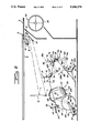
- FIG. 2 is a side elevation of the first embodiment showing the details of mechanism for driving the various optical elements.
- FIG. 3 is a side elevation of an electrophotographic copier employing the first embodiment of FIGS. 1 and 2.
- FIG. 4 is a side elevation of a second embodiment of my invention showing the optical paths for various magnifications.
- FIG. 5 is a fragmentary plan view of the second embodiment showing the details of mechanism for driving the various optical elements.
- FIG. 6 is a diagrammatic side view of an embodiment similar to FIG. 5 wherein focusing is provided by a lens.
- FIGS. 1 through 3 show the first embodiment of my invention.
- An object document 2 to be copied is placed upon transparent platen 4, which is mounted in the top of housing 6 of an electrophotographic copier.
- Light from lamp 8 is reflected by a semi-elliptical reflector 10 and a planar mirror 12 to illuminate a lateral strip of the document.
- Light from the illuminated strip of document 2 is directed to a reflex lens 20 after sequential reflection from transfer optics comprising full-rate scanning mirror 14, half-rate scanning mirror 16, and a mirror 18.
- Reflex lens 20 includes a double convex lens 22 and a planar mirror 24, and is mounted on shaft 26 for rotation about an axis which orthogonally intersects the optical axis of lens 20.
- Light from reflex lens 20 is focused upon a charged photoconductive surface 32 after sequential reflection from transfer optic comprising mirrors 28 and 30.
- the photoconductive layer 32 is mounted on a drum 34.
- the magnification of the image formed by reflex lens 20 upon surface 32 is equal to the ratio of the image distance to the object distance.
- the image on the photoconductive surface is the same size as the document; and the object and image distances from the lens are equal. If the image is to be smaller than the object document 2, so that the magnification is less than unity, then the object distance must be increased and the image distance decreased.
- This reduction in magnification is made by moving mirror 18 to the alternate position 18A, by rotating reflex lens 20 so that its lens and mirror are in the alternate positions 22A and 24A, by moving mirror 28 to the alternate position 28A, and by rotating mirror 30 on its shaft 31 to the alternate position 30A.
- a magnification-changing crank 36 provided with a crank handle 37 is attached to a rotatable drum 38, about which flexible cable 40 is wrapped.
- Cable 40 passes over tensioning pulley 42, which is mounted on a lever 44 journalled on a fixed shaft 46.
- Lever 44 is biased by spring 48 toward spring anchorage 50 to take up slack in cable 40.
- Cable 40 further passes over pulleys 52, 54, and 56 before being returned to drum 38.
- Stop 62 limits counterclockwise rotation of housing 60 to the angular orientation for unity magnification; and stop 64 limits clockwise rotation of housing 60 to the alternate angular orientation 60A for reduced magnification.
- spring 66 is attached to cable 40, and the other is secured to a lever 68, journalled at one end on a shaft 70.
- lever 68 rotatably mounts a shaft 72 to which is secured mirror 18.
- Stops 74 limit counterclockwise rotation of lever 68 and hold mirror 18 in the position and angle for unity magnification.
- Stops 76 limit clockwise rotation of lever 68 and hold mirror 18 in the alternate position and angle 18A for reduced magnification.
- spring 78 One end of spring 78 is attached to cable 40, and the other is secured to a lever 80, journalled at one end on a fixed shaft 82.
- the other end of lever 80 rotatably mounts a shaft 84 to which is secured mirror 28.
- Stops 86 limit clockwise rotation of lever 80 and hold mirror 28 in the position and angle for unity magnification.
- Stops 88 limit counterclockwise rotation of lever 80 and hold mirror 28 in the alternate position and angle 28A for reduced magnification.
- Stop 92 limits clockwise rotation of mirror 30 to the angular orientation for unity magnification.
- Stop 94 limits counterclockwise rotation of mirror 30 to the alternate angular orientation 30A for reduced magnification.
- magnification-changing crank 36 When magnification-changing crank 36 is in the position shown in FIG. 2, the optical system produces unity magnification. Cable 40 is moved counterclockwise along its path, thus moving the attached ends of springs 58, 66, 78, and 90 to the positions shown.
- Spring 58 biases housing 60 against stop 62; spring 66 biases mirror 18 against stops 74; spring 78 biases mirror 28 against stops 86; and spring 90 biases mirror 30 against stop 92.
- Crank 36 is maintained in the position shown by a detenting member 98 which cooperates with a first detent 101 in the surface of drum 38.
- Member 98 is provided with a hemispherical head secured to a shaft which telescopes within a fixed casing 96, and is biased toward engagement with the drum by a coil spring 100.
- crank 36 A reduction in magnification is obtained by rotating crank 36 clockwise to the alternate position 36A. Sufficient manual force must be initially applied to crank handle 37 to cause head 98 to ride out of detent 101 to the surface of drum 38 against the biasing force of spring 100. Thereafter the crank 36 may be easily rotated to its alternate position 36A, where spring 100 forces head 98 into a second detent 102 in the surface of drum 38, to maintain the crank in the alternate position. Cable 40 is moved clockwise along its path, thus moving springs 58, 66, 78, and 90 to the alternate positions shown in FIG. 2.
- Spring 58 now biases housing 60 to the alternate angular orientation 60A against stop 64; spring 66 now biases mirror 18 to the alternate position and angle 18A against stops 76; spring 78 now biases mirror 28 to the alternate position and angle 28A against stops 88; and spring 90 now biases mirror 30 to the alternate angular orientation 30A against stop 94. All of the optical elements are now in the proper position for reduced magnification.
- lamp 8 reflector 10, illuminating mirror 12, and scanning mirror 14 are all mounted on a full-rate carriage 120.
- Mirror 16 is mounted on a half-rate carriage 122. Both the full and half-rate carriages ride upon laterally spaced rails 124 (only one of which is shown). Full-rate carriage 120 and half-rate carriage 122 each move between the positions shown and the alternate positions 120A and 122A.
- Carriages 120 and 122 are moved by a flexible cable 126.
- Cable 126 is attached to a fixed anchorage 132.
- Cable 126 passes half-way around one groove of a two-groove sheave 130, which is rotatably mounted on the half-rate carriage 122, and is then secured to full-rate carriage 120 by clamp 128.
- clamp 1208 cable 126 passes over pulley 134 to drum 136, which is mounted upon the output shaft of a two-speed transmission 138.
- Cable 126 is wound around drum 136 and then passes over tensioning pulley 140, journalled at one end of lever 142.
- the other end of lever 142 is journalled on a fixed shaft 144.
- Lever 142 is biased by a spring 146 attached to anchorage 148.
- Cable 126 then passes over pulley 150, passes half-way around the other groove of sheave 130, and is attached to a fixed anchorage 152.
- the portion of cable 126 from clamp 128 to sheave 130 is parallel to the portion of cable from sheave 130 to anchorage 132. Since cable 126 is fixedly attached to both clamp 128 and anchorage 132, the sum of the lengths of these two cable portions is constant When carriage 122 moves toward anchorage 132, the length of cable from sheave 130 to anchorage 132 decreases, while the length of cable from sheave 130 to clamp 128 increases.
- the movement of clamp 128 is the sum of the movement of clamp 128 relative to sheave 130 and the movement of carriage 122. Thus, carriage 120 moves twice as fast as carriage 122.
- the image field upon photoconductive surface 32 likewise moves.
- surface 32 must move at a velocity which is equal to the product of the scanning speed of mirror 14 and the magnification of the image focussd upon surface 32.
- FIG. 3 shows a mechanism for synchronizing the motion of photoconductive surface 32 with that of scanning mirror 14 at two different magnifications.
- Motor 162 rotates a sprocket 164 which drives a chain 166.
- Chain 166 rotates a first sprocket 168 mounted on an input shaft of two-speed transmission 138 and a second sprocket 170 mounted on the supporting shaft of drum 34.
- Rotation of sprocket 168 causes transmission 138 to rotate drum 136. This moves cable 126 and causes the full-rate and half-rate carriages to scan document 2.
- Rotation of sprocket 170 causes drum 34 to rotate, moving photoconductive surface 32 in synchronism with carriage 120.
- a cable 154 Also wound partially around drum 38 and attached thereto is a cable 154. Cable 154 passes over pulley 156 to a gear shifting lever 158 of two-speed transmission 138. With crank 36 in the position shown cable 154 maintains gear shift lever 158 in the position shown, which provides the proper gear ratio for unity magnification. With this gear ratio, the peripheral velocity of the photoconductive surface 32 of drum 34 is equal to the velocity of carriage 120.
- crank 36 is rotated clockwise to the position 36A shown in FIG. 2, cable 154 unwinds from drum 38, permitting spring 160 to pull shift lever 158 to the right and set transmission 138 to the proper gear ratio for reduced magnification. If the reduced magnification is one-half, for example, then the gear ratio must be doubled to ensure that carriage 120 moves at a velocity which is twice that of the peripheral surface 32 of drum 34.
- FIGS. 4 and 5 show an alternate embodiment of my invention.
- Document 200 to be copied is placed upon transparent platen 202 mounted in the top of housing 204 of an electrophotographic copier.
- Light from lamp 206 is reflected from reflector 208 and mirror 210 to illuminate a narrow strip of document 200.
- Light from this illuminated strip is directed to reflex lens 216 after sequential reflection from transfer optics comprising full-rate scanning mirror 212 and half-rate mirror 214.
- Reflex lens 216 is of fixed focal length and comprises lens 218 and mirror 220, both mounted to rotate as a unit about the axis 228 of a shaft 238 (FIG. 5).
- Light from lens 216 is focused upon the photoconductive surface 224 of drum 226 after reflection from transfer optic comprising mirror 222 to produce an image the magnification of which is unity, for example.
- reflex lens 216 is rotated about axis 228 to the position 216A. Since the rotational axis 228 is orthogonal to, but appreciably displaced from, the optical axis of reflex lens 216, there results an appreciable displacement of the optical center of lens 216.
- reflex lens 216 unmasks a mirror 230; and light from half-rate mirror 214 passes to lens 216A only after reflection from mirror 230. This increases the object distance.
- Light from lens 216A is now focused on photoconductive surface 224 after sequential reflection from mirrors 232A and 234.
- Mirror 232 is mounted on a rotatable shaft 233. For unity magnification, mirror 232 is in the position shown where it does not intercept the light path from mirror 222 to photoconductive surface 224. For reduced magnification, mirror 232 is rotated by shaft 233 to the alternate position 232A. The increased ratio of object distance to image distance reduces the magnification while maintaining a properly focused image.
- FIG. 5 shows a mechanism for moving the optical elements 216 and 232 of FIG. 4 to change the magnification.
- shaft 238 By moving magnification-changing crank handle 236 from the position shown to the alternate position 236A, shaft 238 is rotated.
- Shaft 238 comprises two sections disposed on either side of an eccentric or yoke 240 on which reflex lens 216 is mounted. The two sections of shaft 238 are coaxial with rotational axis 228.
- Shaft 238 is mounted for both rotation and translation by bearings 242 and 246.
- Bearing 242 is formed with a helical cam slot 248 in which rides a pin 250 mounted in the upper section of shaft 238.
- Pulley 252 is mounted on the lower section of shaft 238 inboard of bearing 246.
- the lower section of shaft 238 is provided with an elongated slot 264; and pulley 252 is provided with a pin or key (not shown) which rides in slot 264.
- rotational movement of shaft 238 causes rotational movement of pulley 252; but translational movement of shaft 238 relative to pulley 252 is accommodated.
- arm 245 Secured to bearing 246 is an arm 245 which mounts a keeper or thrust bearing 244 preventing axial motion of pulley 252.
- Flexible belt 254 couples pulley 252 to another pulley 256, which is mounted on shaft 233.
- Shaft 233 is rotatably supported by bearings 260 and 262.
- crank 236 rotates shaft 233 and mirror 232 which is secured thereto.
- Pulley 256 is nearly twice the diameter of pulley 252 since the rotation of mirror 232 for a change of magnification is only slightly greater than 90°.
- cam slot 248 serve as stops accurately to fix the positions of yoke 240, and hence mirror 232, for each magnification.
- Gravity acting on the eccentrically mounted reflex lens 216 biases pin 250 against the inboard end of slot 248 in the position shown In the alternate position, gravity biases pin 250A against the outboard end of slot 248.
- FIG. 6 is similar to the embodiment of FIG. 5, but focusing is provided by a plano-convex lens 217.
- the object 0 may be original document 200.
- the image I may be photoconductive surface 224.
- Yoke 240 supports lens 217 for rotation on shaft 238.
- Shaft 238 may be translated along its axis 228.
- the focal length of lens 217 may be 1.5 inches, for example; and the total distance between object 0 and image I may be 6.75 inches.
- the magnification of the image is two; and the distance of the object 0 from lens 217 is 2.25 inches while the distance of the image I from lens 217 is 4.5 inches.
- Shaft 238 is positioned 3.375 inches distant from both the object 0 and the image I.
- the length of the arm of yoke 240 is 1.125 inches. Rotation of shaft 238 through 180° rotates yoke 240A and lens 217A to the positions shown in broken lines. The magnification of the image is one-half; and the object distance is now 4.5 inches while the image distance is now 2.25 inches.
- lens 217-217A In rotating from the position shown to the alternate position, lens 217-217A not only moves 2.25 inches to the right along the O - I axis, but also is flipped over so that its more plano surface is associated with the shorter of the object and image distances, while its more convex surface is associated with the larger of the object and image distances.
- Lens 217 has a shape factor which is negative, while the very same lens 217A has a shape factor which is positive because of its 180° rotation.
- the magnitude of the shape factor is such as to reduce spherical aberration to a minimum. This bending of the lens insures that a marginal ray enters the left-hand lens surface and leaves the right-hand lens surface at substantially equal angles so that there is nearly equal refraction at both surfaces.
- lens 217 were merely translated to the right, there would be no reversal of its shape factor; and spherical aberration would be very large for an image magnification of one-half.
- the rotation of lens 217-217A through 180° insures that spherical aberration is a minimum at both image magnifications.
- the rotational axis may substantially intersect the optical axis as in FIG. 1 or may be appreciably displaced from the optical axis as in FIG. 4. Since no translation of the focusing means along its optical axis is needed, the construction is simple and inexpensive while providing accurate focusing at various magnifications.
Abstract
Description
Claims (10)
Priority Applications (1)
| Application Number | Priority Date | Filing Date | Title |
|---|---|---|---|
| US07/122,530 US5146276A (en) | 1978-11-09 | 1987-11-19 | Rotatable focusing means and variable magnification electrophotocopier |
Applications Claiming Priority (2)
| Application Number | Priority Date | Filing Date | Title |
|---|---|---|---|
| US95930378A | 1978-11-09 | 1978-11-09 | |
| US07/122,530 US5146276A (en) | 1978-11-09 | 1987-11-19 | Rotatable focusing means and variable magnification electrophotocopier |
Related Parent Applications (1)
| Application Number | Title | Priority Date | Filing Date |
|---|---|---|---|
| US06398841 Continuation | 1982-07-16 |
Publications (1)
| Publication Number | Publication Date |
|---|---|
| US5146276A true US5146276A (en) | 1992-09-08 |
Family
ID=26820629
Family Applications (1)
| Application Number | Title | Priority Date | Filing Date |
|---|---|---|---|
| US07/122,530 Expired - Lifetime US5146276A (en) | 1978-11-09 | 1987-11-19 | Rotatable focusing means and variable magnification electrophotocopier |
Country Status (1)
| Country | Link |
|---|---|
| US (1) | US5146276A (en) |
Cited By (1)
| Publication number | Priority date | Publication date | Assignee | Title |
|---|---|---|---|---|
| EP0751665A2 (en) * | 1995-06-29 | 1997-01-02 | Bayer Corporation | Method and apparatus for positioning a focusing lens |
Citations (16)
| Publication number | Priority date | Publication date | Assignee | Title |
|---|---|---|---|---|
| GB698171A (en) * | 1948-03-31 | 1953-10-07 | Joseph Danek | Improvements in photographic enlargers |
| GB902909A (en) * | 1957-11-04 | 1962-08-09 | Hoh & Hahne Hohlux G M B H | Improvements in or relating to a process camera with automatic electrically controlled accurate focussing |
| US3572924A (en) * | 1967-10-12 | 1971-03-30 | Tokyo Shibaura Electric Co | Copying apparatus |
| US3614222A (en) * | 1970-04-24 | 1971-10-19 | Olivetti & Co Spa | Optical drive system for reproducing machine |
| US3876302A (en) * | 1972-11-02 | 1975-04-08 | Dick Co Ab | High speed low inertia scanning system for a copying machine |
| GB1437892A (en) * | 1973-11-29 | 1976-06-03 | Ibm | Optical scanning system |
| US3999850A (en) * | 1972-04-13 | 1976-12-28 | Canon Kabushiki Kaisha | Optical system for an electrophotographic device |
| US4013361A (en) * | 1975-06-20 | 1977-03-22 | Xerox Corporation | Optical apparatus and reproducing machine |
| US4029409A (en) * | 1975-06-20 | 1977-06-14 | Xerox Corporation | Multi-mode optical scanning system |
| US4033692A (en) * | 1975-10-30 | 1977-07-05 | Xerox Corporation | Multi-mode reproducing machine |
| US4060324A (en) * | 1975-11-21 | 1977-11-29 | Rank Xerox Ltd. | Lens switching mechanism for use in copying machine |
| GB1512838A (en) * | 1974-06-28 | 1978-06-01 | Oce Van Der Grinten Nv | Photographic copying |
| US4116562A (en) * | 1972-10-27 | 1978-09-26 | International Business Machines | Optical system featuring change in magnification by combined lens and mirror motion |
| US4118118A (en) * | 1976-05-07 | 1978-10-03 | Universal Photocopy, Inc. | Electrostatic copier machine with selectable magnification ratios |
| GB1527860A (en) * | 1976-09-07 | 1978-10-11 | Ibm | Electrophotographic reproducing machine |
| US4129379A (en) * | 1976-11-17 | 1978-12-12 | Ogrisek Harriet H | Optical system for electrostatic copiers |
-
1987
- 1987-11-19 US US07/122,530 patent/US5146276A/en not_active Expired - Lifetime
Patent Citations (17)
| Publication number | Priority date | Publication date | Assignee | Title |
|---|---|---|---|---|
| GB698171A (en) * | 1948-03-31 | 1953-10-07 | Joseph Danek | Improvements in photographic enlargers |
| GB902909A (en) * | 1957-11-04 | 1962-08-09 | Hoh & Hahne Hohlux G M B H | Improvements in or relating to a process camera with automatic electrically controlled accurate focussing |
| US3572924A (en) * | 1967-10-12 | 1971-03-30 | Tokyo Shibaura Electric Co | Copying apparatus |
| US3614222A (en) * | 1970-04-24 | 1971-10-19 | Olivetti & Co Spa | Optical drive system for reproducing machine |
| US3999850A (en) * | 1972-04-13 | 1976-12-28 | Canon Kabushiki Kaisha | Optical system for an electrophotographic device |
| US4116562A (en) * | 1972-10-27 | 1978-09-26 | International Business Machines | Optical system featuring change in magnification by combined lens and mirror motion |
| US3876302A (en) * | 1972-11-02 | 1975-04-08 | Dick Co Ab | High speed low inertia scanning system for a copying machine |
| GB1437892A (en) * | 1973-11-29 | 1976-06-03 | Ibm | Optical scanning system |
| GB1512838A (en) * | 1974-06-28 | 1978-06-01 | Oce Van Der Grinten Nv | Photographic copying |
| US4013361A (en) * | 1975-06-20 | 1977-03-22 | Xerox Corporation | Optical apparatus and reproducing machine |
| US4029409A (en) * | 1975-06-20 | 1977-06-14 | Xerox Corporation | Multi-mode optical scanning system |
| GB1538492A (en) * | 1975-06-20 | 1979-01-17 | Xerox Corp | Electrostatographic printing apparatus |
| US4033692A (en) * | 1975-10-30 | 1977-07-05 | Xerox Corporation | Multi-mode reproducing machine |
| US4060324A (en) * | 1975-11-21 | 1977-11-29 | Rank Xerox Ltd. | Lens switching mechanism for use in copying machine |
| US4118118A (en) * | 1976-05-07 | 1978-10-03 | Universal Photocopy, Inc. | Electrostatic copier machine with selectable magnification ratios |
| GB1527860A (en) * | 1976-09-07 | 1978-10-11 | Ibm | Electrophotographic reproducing machine |
| US4129379A (en) * | 1976-11-17 | 1978-12-12 | Ogrisek Harriet H | Optical system for electrostatic copiers |
Non-Patent Citations (4)
| Title |
|---|
| Day, Pierce B; "Size Reduction Imaging Means"; Research Disclosure, Aug. 1976, p. 12, No. 14820. |
| Day, Pierce B; Size Reduction Imaging Means ; Research Disclosure, Aug. 1976, p. 12, No. 14820. * |
| IBM Technical Disclosure Bulletin, vol. 15, No. 4 (Sep. 1972), pp. 1366 and 1367 "Two-Mirror Copier Scanner". |
| IBM Technical Disclosure Bulletin, vol. 15, No. 4 (Sep. 1972), pp. 1366 and 1367 Two Mirror Copier Scanner . * |
Cited By (2)
| Publication number | Priority date | Publication date | Assignee | Title |
|---|---|---|---|---|
| EP0751665A2 (en) * | 1995-06-29 | 1997-01-02 | Bayer Corporation | Method and apparatus for positioning a focusing lens |
| EP0751665A3 (en) * | 1995-06-29 | 2000-04-12 | Agfa Corporation | Method and apparatus for positioning a focusing lens |
Similar Documents
| Publication | Publication Date | Title |
|---|---|---|
| US4209248A (en) | Continuously variable reduction copier optics systems | |
| US4120578A (en) | Continuously variable reduction scanning optics drive | |
| US4135812A (en) | Magnification change mechanism | |
| US5146276A (en) | Rotatable focusing means and variable magnification electrophotocopier | |
| US4571064A (en) | Optical element positioning apparatus for use in electrophotographic copying machine | |
| GB2034489A (en) | Variable magnification copier | |
| CA1217227A (en) | Compact optical scanning system | |
| US4015892A (en) | Optical scanning system for slitwise exposure | |
| US4464046A (en) | Copying machine capable of continuously varying magnification | |
| US5075719A (en) | Lens driving device | |
| US4947213A (en) | Projection copying apparatus | |
| US4708463A (en) | Device for enlarging and projecting microfilm image | |
| US4533228A (en) | Optical image projector for projecting an erect positive image of unity magnification and for minimizing degradation in resolution | |
| US4998135A (en) | Mechanism for moving a projection lens assembly to alter projecting magnification | |
| US4854672A (en) | Optical system for copier | |
| JPS6059336A (en) | Magnification varying device of copying machine | |
| EP0068000A1 (en) | Multiple magnification optical assembly | |
| JPS5842456B2 (en) | Magnification changing device in copying machines, etc. | |
| JPS6180141A (en) | Variable power mechanism of copying machine | |
| KR840001155Y1 (en) | Magnificatron changing apparatus for use in duplicators | |
| JPS63179345A (en) | Optical device for copying machine | |
| JP2899232B2 (en) | Image reading device | |
| JPS62115146A (en) | Interlocking device for lens and mirror in variable power device | |
| JPS58102261A (en) | Optical device of copying machine | |
| JPS5843728B2 (en) | Hengbaikikouoyuusuru Gazokeiseisouchi |
Legal Events
| Date | Code | Title | Description |
|---|---|---|---|
| FEPP | Fee payment procedure |
Free format text: PAYOR NUMBER ASSIGNED (ORIGINAL EVENT CODE: ASPN); ENTITY STATUS OF PATENT OWNER: LARGE ENTITY |
|
| AS | Assignment |
Owner name: SPECTRUM SCIENCES B.V., NETHERLANDS Free format text: ASSIGNMENT OF ASSIGNORS INTEREST.;ASSIGNORS:FOOTHILL CAPITAL CORPORATION;SAVIN CORPORATION;REEL/FRAME:006027/0914 Effective date: 19920228 Owner name: SAVIN CORPORATION, CONNECTICUT Free format text: ASSIGNMENT OF ASSIGNORS INTEREST.;ASSIGNORS:FOOTHILL CAPITAL CORPORATION;SAVIN CORPORATION;REEL/FRAME:006027/0914 Effective date: 19920228 |
|
| STCF | Information on status: patent grant |
Free format text: PATENTED CASE |
|
| FEPP | Fee payment procedure |
Free format text: PAYER NUMBER DE-ASSIGNED (ORIGINAL EVENT CODE: RMPN); ENTITY STATUS OF PATENT OWNER: LARGE ENTITY Free format text: PAYOR NUMBER ASSIGNED (ORIGINAL EVENT CODE: ASPN); ENTITY STATUS OF PATENT OWNER: LARGE ENTITY |
|
| CC | Certificate of correction | ||
| AS | Assignment |
Owner name: INDIGO N.V., NETHERLANDS Free format text: CHANGE OF NAME AND ADDRESS EFFECTIVE 6-8-93.;ASSIGNOR:SPECTRUM SCIENCES B.V. ZIJDEEWEG 6 2244 BG WASSENAAR, THE NETHERLANDS;REEL/FRAME:006850/0595 Effective date: 19940126 |
|
| FPAY | Fee payment |
Year of fee payment: 4 |
|
| FPAY | Fee payment |
Year of fee payment: 8 |
|
| FPAY | Fee payment |
Year of fee payment: 12 |