US5146882A - Method and apparatus for cold starting a spark ignited internal combustion engine fueled with an alcohol-based fuel mixture - Google Patents
Method and apparatus for cold starting a spark ignited internal combustion engine fueled with an alcohol-based fuel mixture Download PDFInfo
- Publication number
- US5146882A US5146882A US07/750,357 US75035791A US5146882A US 5146882 A US5146882 A US 5146882A US 75035791 A US75035791 A US 75035791A US 5146882 A US5146882 A US 5146882A
- Authority
- US
- United States
- Prior art keywords
- engine
- fuel
- cylinder
- spark plug
- cranking
- Prior art date
- Legal status (The legal status is an assumption and is not a legal conclusion. Google has not performed a legal analysis and makes no representation as to the accuracy of the status listed.)
- Expired - Lifetime
Links
Images


Classifications
-
- F—MECHANICAL ENGINEERING; LIGHTING; HEATING; WEAPONS; BLASTING
- F02—COMBUSTION ENGINES; HOT-GAS OR COMBUSTION-PRODUCT ENGINE PLANTS
- F02P—IGNITION, OTHER THAN COMPRESSION IGNITION, FOR INTERNAL-COMBUSTION ENGINES; TESTING OF IGNITION TIMING IN COMPRESSION-IGNITION ENGINES
- F02P3/00—Other installations
- F02P3/02—Other installations having inductive energy storage, e.g. arrangements of induction coils
-
- F—MECHANICAL ENGINEERING; LIGHTING; HEATING; WEAPONS; BLASTING
- F02—COMBUSTION ENGINES; HOT-GAS OR COMBUSTION-PRODUCT ENGINE PLANTS
- F02D—CONTROLLING COMBUSTION ENGINES
- F02D41/00—Electrical control of supply of combustible mixture or its constituents
- F02D41/02—Circuit arrangements for generating control signals
- F02D41/04—Introducing corrections for particular operating conditions
- F02D41/06—Introducing corrections for particular operating conditions for engine starting or warming up
- F02D41/062—Introducing corrections for particular operating conditions for engine starting or warming up for starting
-
- F—MECHANICAL ENGINEERING; LIGHTING; HEATING; WEAPONS; BLASTING
- F02—COMBUSTION ENGINES; HOT-GAS OR COMBUSTION-PRODUCT ENGINE PLANTS
- F02P—IGNITION, OTHER THAN COMPRESSION IGNITION, FOR INTERNAL-COMBUSTION ENGINES; TESTING OF IGNITION TIMING IN COMPRESSION-IGNITION ENGINES
- F02P15/00—Electric spark ignition having characteristics not provided for in, or of interest apart from, groups F02P1/00 - F02P13/00 and combined with layout of ignition circuits
- F02P15/12—Electric spark ignition having characteristics not provided for in, or of interest apart from, groups F02P1/00 - F02P13/00 and combined with layout of ignition circuits having means for strengthening spark during starting
Definitions
- This invention relates to a method and apparatus for cold starting an engine, and more particularly, to a method and apparatus for enhancing the cold starting capability of a spark ignition, internal combustion engine, which is fueled with an alcohol-based fuel mixture.
- alcohol fuels such as ethanol and methanol
- ethanol and methanol have been proposed as possible alternatives to gasoline for fueling conventional internal combustion engines. It is well known that engines using these alternative fuels generally can not be started at low ambient temperatures, due to the higher heats of vaporization, lower vapor pressures, and the higher fuel concentrations required to achieve stoichiometric fuel-air mixtures for alcohol fuels.
- M-85 an alcohol-based fuel that is gaining popularity as a commercially feasible automobile fuel.
- M-85 an alcohol-based fuel that is gaining popularity as a commercially feasible automobile fuel.
- M-85 This fuel is formed by mixing 15% gasoline with 85% methanol.
- Testing has shown that conventional engines generally can not be started at ambient temperatures below -20° C. with the M-85 fuel, which is still significantly higher than a desired minimum cold starting temperature of -29° C., that is a commonly used standard for automobiles.
- a sufficient quantity of fuel must be delivered to establish a combustible fuel vapor-air mixture in the vicinity of each engine spark plug, without causing subsequent cylinder misfires
- cylinder misfiring in engine fuel with alcohol-based mixtures is due in part to the electrically conductive nature of the alcohol-based fuels, which resistively loads wetted spark plug arc gaps.
- the amount of fuel delivered to the engine is increased in a conventional fashion to establish a combustible fuel vapor-air mixture in the engine cylinders at a low ambient temperature
- the amount of unvaporized fuel accumulating in the engine cylinders also increases.
- the resistance shunting each wetted spark plug arc gap decreases in value.
- the magnitude of the peak ignition current supplied to each cylinder spark plug is not sufficient to achieve the break down voltage of the arc gaps and ignite the vaporized fuel. Consequently, the engine misfires and starting is prevented.
- the engine cold starting performance is enhanced by (1) deriving an indication of the engine temperature; (2) deriving an indication of the relative proportion of alcohol to gasoline in the fuel mixture; (3) deriving an indication of the cumulative number of engine revolutions during cranking; (4) delivering a scheduled quantity of fuel to the engine, as the engine is cranked for starting, where the scheduled quantity of fuel is determined as a function of the derived indications for the engine temperature, the relative proportion of alcohol to gasoline in the fuel mixture, and the cumulative number of cranking engine revolutions, so as to establish a combustible fuel vapor-air mixture in each engine cylinder, while restricting the accumulation of unvaporized fuel in each cylinder so as not to exceed a predetermined amount; and (5) providing each cylinder spark plug with an ignition current having
- the quantity of fuel initially delivered to the engine at the start of cranking is determined as a function of the derived indications for the engine temperature and the relative proportion of alcohol to gasoline in the fuel mixture, and thereafter, the quantity of delivered fuel is reduced during cranking to effectuate a delivered fuel-air ratio that decreases at a substantially exponential rate as a function of the cumulative number of cranking revolutions of the engine. More specifically, a 20% reduction in the injected fuel-air ratio for every engine cycle during cranking (or every two revolutions of the crankshaft in a four-stroke engine) was found to be optimum, in that it enabled the largest quantity of fuel to be delivered at the initiation of cranking, without producing subsequent cylinder misfires. Consequently, a combustible fuel vapor-air mixture is rapidly established in the engine cylinders to provide fast first firing during starting.
- a modified ignition coil having a secondary to primary winding turns ratio in the order of 65:1 and having its secondary winding wrapped onto a plurality of partitions in a segmented dielectric bobbin was utilized to increase the peak ignition current provided to each cylinder spark plug.
- This coil was found to provide a peak ignition current in excess of 100 mA, which is sufficient to fire typical spark plugs having shunting resistances as low as 200 k ⁇ across their arc gaps due to wetting by unvaporized fuel in the engine cylinders.
- M-85(HVG) methanol fuel mixture
- the M-85(HVG) fuel is formed by mixing 85% methanol with 15% high volatility gasoline having a Reid Vapor Pressure (RVP) of 14.
- RVP Reid Vapor Pressure
- FIG. 1 schematically illustrates an internal combustion engine, which is operated on an alcohol-based fuel mixture, and the associated ignition and computer control systems, which include the present invention for improving engine cold starting performance;
- FIG. 2 schematically illustrates components included within a conventional direct ignition system
- FIG. 3 illustrates a top plan view of a modified ignition coil for the direct ignition system utilized in the preferred embodiment of the present invention
- FIG. 4 shows a sectional elevation view of the modified ignition coil of FIG. 3 taken along the line A--A;
- FIG. 5 provides a graphical representation comparing the ignition current supplied by the secondary winding of a conventional direct ignition coil and the ignition current supplied by the modified direct ignition coil employed in the preferred embodiment of the present invention
- FIG. 6 provides a graphical representation of the computed fuel vapor-air equivalence ratio for M-85(HVG) methanol fuel as a function of the injected fuel-air ratio, at -29° C. and standard atmospheric pressure;
- FIG. 7 provides a graphical representation comparing a typical optimized schedule for regulating the injected fuel-air ratio (assuming 100% volumetric efficiency) as a function of cranking revolutions, with the actual fuel-air ratio (assuming 100% volumetric efficiency) that was achieved in a practical implementation of the present invention
- FIGS. 8A-B provide a flow diagram representative of the steps executed by the electronic control unit of FIG. 1, when scheduling the delivery of alcohol-based fuel during engine cold starting in accordance with the principles of the present invention.
- FIG. 9 provides a graphical representation of typical values for standard gasoline and alcohol cold start multipliers used for scheduling the delivery of a methanol-gasoline fuel mixture during engine cranking for cold starting.
- FIG. 1 there is shown schematically an internal combustion engine, generally designated as 10, which is fueled with an alcohol-based fuel mixture.
- a portion of the exterior of engine 10 has been removed to expose a cylinder denoted by the numeral 1.
- Piston 14 resides within the wall of cylinder 1, with rod 16 connecting piston 14 to a rotatable engine crankshaft (not shown).
- a solenoid driven fuel injector 18 projects into an intake port 20 for delivering fuel to the associated cylinder 1.
- Cylinder 1 is additionally provided with a spark plug S1, which has an arc gap 22 for igniting fuel delivered to the cylinder 1.
- intake valve 26 and exhaust valve 28 which are opened and closed in timed relationship with the rotation of the engine crankshaft to enable the intake of fuel into cylinder 1 and the exhaust of burned fuel components after combustion.
- engine 10 is preferably a multi-cylinder engine, even though only a single cylinder 1 is illustrated in FIG. 1 to simplify the description.
- engine 10 is controlled by a conventional electronic computer control system, which includes an electronic control unit (ECU) 30, an electronic ignition system 31, and several standard sensors that provide information related to the engine operating conditions.
- ECU electronice control unit
- the ECU 30 is a conventional digital computer used by those skilled in the art of engine control, and includes the standard elements of a central processing unit, random access memory, read only memory, non-volatile memory, analog-to-digital converter, input/output circuitry, and clock circuitry.
- a standard coolant temperature sensor 32 provides the ECU 30 with a TEMP input signal, which is indicative of the temperature within engine 10 (and also, the ambient temperature when the engine is cold started).
- the ECU 30 is also provided with a fuel composition input signal ALC %, which indicates the composition of the alcohol-based fuel delivered to engine 10.
- the ALC % input signal is obtained from a fuel composition sensor 34, which is positioned close to engine 10, in a fuel supply line 36 communicating with fuel injector 18.
- the fuel composition sensor can be of any known type, such as a capacitive dielectric sensor described in U.S. Pat. Nos. 4,915,084 and 4,971,051, which to E. V. Gonze on Apr. 10, 1990 and Nov. 20, 1990, respectively, and have been assigned to the assignee of the present application. This capacitive sensor measures the dielectric constant of the fuel delivered to engine 10, and generates a signal corresponding to the relative proportion of alcohol to gasoline in the fuel mixture.
- the ignition system 31 illustrated in FIG. 1 is a direct ignition system (DIS), which does not include a distributor.
- DIS direct ignition system
- Such systems are known in the automotive art, see for example U.S. Pat. Nos. 4,711,226 and 4,750,467, which respectively issued to Neuhalfen et al on Dec. 8, 1987 and Neuhalfen on Jun. 14, 1988, and which have been assigned to the assignee of the present application.
- the DIS system typically contains a DIS electronic ignition module and separate inductive ignition coils for each pair of cylinders present in engine 10.
- the ignition system 31 is provided with an input signal POS indicating the rotational position of the engine crankshaft.
- the POS signal may be obtained from a standard rotational sensor such as slotted wheel and electromagnetic sensor 40.
- the slotted wheel 38 is mechanically coupled to the engine crankshaft, and contains six equally spaced slots, with one additional asymmetrically spaced slot for synchronization. As wheel 38 is rotated by the crankshaft, the electromagnetic sensor 40 detects the passage of the slots and generates corresponding pulses in the POS input signal.
- a conventional ignition switch 42 is used to start and run engine 10.
- the ignition switch 42 has three stationary contacts 46, 48, and 50, with a manually movable contact 52.
- movable contact 52 is positioned in the open position, but can be rotated to a "crank” position, where it simultaneously bridge stationary contacts 50 and 48, or to a "run” position, where it bridges contacts 46 and 48.
- the movable contact 52 of ignition switch 42 is normally spring biased to return to the run position, after the engine is running and the movable contact 52 is released. In the run position the potential of battery 44 continues to be applied to the ignition system 31 and the ECU 30 through contact 48, and to any accessory circuits connected to contact 46.
- the passage of slots in wheel 38 are detected by sensor 40, which generates corresponding pulses in the PO$ input signal directed to the ignition system 31.
- a REF input signal to the ECU 30 is switched from a low to a high state.
- the REF input is toggled to change states (switched from low-to-high or high-to-low), only when one of the six equally spaced slots on wheel 38 is detected.
- the REF input signal contains three pulses per revolution of the engine, with the rising and falling edges of each pulse corresponding to the detection of one of the six equally spaced slots on wheel 38.
- the ECU 30 utilizes the reference pulses provided by the synchronized REF input to determine the rotational speed and crankshaft engine 10, the ECU 30 computes fuel injection and spark timing information, as well as the appropriate quantity of alcohol-based fuel to supply to engine 10 (see for example, U.S. Pat. No 4,915,084 issued to Gonze on Apr. 10, 1990, and assigned to the same assignee of the present application). Based on this computed information, the ECU 30 outputs a timed FUEL PULSE to the solenoid of fuel injector 18, where the width of the FUEL PULSE is proportional to the quantity of fuel sprayed into intake port 20 by fuel injector 18.
- ECU 30 During normal engine running, ECU 30 provides the ignition system 31 with a conventional spark advance signal EST to properly time the SPARK energy delivered to the spark plug S2. However, when the engine is cranked to start and/or the engine speed is below a predetermined speed (for example, 400 RPM), the ignition system 31 is operated in a bypass mode. Operation in this mode is indicated by the BYPASS signal provided by the ECU 30. During bypass operation, the ignition timing is determined by the ignition system 31 alone, without the use of the EST signal.
- a predetermined speed for example, 400 RPM
- FIG. 2 there is shown a more detailed schematic representation of the components present in the conventional direct ignition system (DIS) 31, which for the purpose of the present description is configured for operation with an engine 10 having six-cylinders designated respectively by the numerals 1-6.
- the cylinder firing order for engine 10 will be considered as 1-2-3-4-5-6, where the pair of pistons in cylinders 1 and 4 each reach top dead center (TDC) simultaneously (one at top of its compression stroke, the other at the top of its exhaust stroke), and likewise for the pair of pistons in cylinders 2 and 5, and the pair in cylinders 3 and 6.
- TDC top dead center
- spark plugs associated with cylinders 1-6 are designated as S1-S6, respectively, and are represented by the standard double arrowed gap symbols shown in FIG. 2.
- the direct ignition system 31 is a distributorless ignition system in that it does not utilize a rotor and distributor cap contacts for sequentially distributing spark firing energy to the engine spark plugs. Instead, each pair of engine cylinders, for which TDC occurs simultaneously, has a separate ignition coil for their associated spark plugs.
- spark plugs S1 and S4 are shown connected to the secondary winding 60 of ignition coil C1; spark plugs S2 and S5 are connected to the secondary winding 62 of ignition coil C2; and spark plugs S3 and S6 are connected to the secondary winding 64 of ignition Coil C3.
- ignition coils C1, C2, and C3 have primary windings 66, 68, and 70, respectively, that are electromagnetically linked to their corresponding secondary windings through ferromagnetic cores 72, 74, and 76.
- Each side of the primary windings 66, 68, and 70 are connected to a DIS electronic ignition module 78.
- the DIS ignition module 78 and ignition coils C1, C2, and C3, such as described above, have been commercially available since 1987 as components in conventional direct ignition systems for 2.8 and 3.1 liter engines in vehicles, such as the Chevrolet Celebrity, produced and sold by General Motors Corporation.
- the DIS electronic ignition module 78 includes semiconductor switches (typically transistors that are not shown) for controlling the current flowing through the primary windings of the ignition coils C1, C2, and C3. As is well known, each primary winding is connected in series with a separate semiconductor switch and the voltage potential provided to ignition system 31 by the battery 44. Each semiconductor switch is normally biased to establish a predetermined current flow through each ignition coil primary winding (for example, 8.5 amperes in the preferred embodiment).
- the DIS electronic ignition module 78 opens each semiconductor switch, at the appropriate time during the engine cycle, to interrupt the established current flowing through the primary winding in each of the ignition coil C1-C3.
- the corresponding magnetic field established in the respective ferromagnetic core 72, 4, or 76 collapses, which in turn induces an ignition current in the secondary winding 60, 62, or 64 of the respective ignition coil.
- the coils C1, C2, and C3 are designed to produce a secondary ignition current having a peak magnitude in the range of 50 to 60 mA. A peak ignition current in this range is generally sufficient to achieve the arc gap breakdown voltage for spark plugs in conventional gasoline fueled engines, unless the arc gaps are carbon fouled.
- the peak ignition current provided by the secondary winding of an inductive ignition system is given approximately by the maximum primary current divided by the secondary to primary turns ratio for the windings of the ignition coil.
- this peak ignition current is not meant to include the transitory current spikes that generally are associated with the electrical breakdown of a spark plug arc gap.
- the peak ignition current can be measured without these transient current spikes by replacing the spark plug loading the secondary winding of an ignition coil with a series of Zener diodes having a combined break down voltage in the order of 800 volts.
- each coil C1, C2, and C3 is connected in series with a different pair of spark plugs as shown in FIG. 2.
- the circuitry within the DIS electronic ignition module 78 appropriately times the interruption of current through the primary winding of each ignition coil so that each pair of spark plugs are fired simultaneously, while one of the associated cylinders is in the compression stroke and the other is in the exhaust stroke, and vice versa.
- each pair of spark plugs is fired once during every complete revolution of the engine, or twice during an engine cycle in a four-stroke engine.
- one of the major problems associated with fueling engine 10 with an alcohol-based fuel is the inability to start the engine at low ambient temperatures.
- a sufficient amount of fuel must be vaporized to provide a combustible fuel vapor-air mixture in the vicinity of each engine spark plug.
- past attempts to achieve such a combustible fuel vapor-air mixture by increasing the quantity of alcohol-based fuel delivered to the engine during cold starting have been unsuccessful, due to repeated engine misfires.
- Engine misfires result when spark plug arc gaps are wetted by the unvaporized portion of an alcohol-based fuel that accumulates in the engine cylinders.
- alcohol-based fuels have an electrical conductivity significantly larger than that of conventional gasoline (7 to 9 orders of magnitude), which is due to the relatively high concentration of dissolved ions made possible by the large dipole moments of alcohol-based fuels. Due to the conductive nature of alcohol-based fuels, the wetting of spark plugs produces resistive loading across the spark plug arc gaps. As the quantity of fuel delivered to the engine is increased to establish a combustible fuel vapor-air mixture in the engine cylinders at a low ambient temperature, the amount of unvaporized liquid fuel accumulating in the engine cylinders also increases.
- a fuel known as M-85(HVG) will be used as an example of an alcohol-based fuel in the remainder of the specification.
- This fuel is formed by mixing 85% methanol with 15% high volatility gasoline having a Reid Vapor Pressure (RVP) of 14 psi.
- RVP Reid Vapor Pressure
- the small quantity of gasoline added to the methanol increases the vapor pressure of the fuel mixture, and enables conventional engines operating on this fuel to be started at ambient temperatures down to approximately -20° C. This is still significantly higher than the which is a commonly used at the desired standard for automobiles.
- the present invention is applicable to alcohol-based fuels in general, and the use of the specific M-85(HVG) fuel for the purpose of explanation should not be considered to limit the invention in any way to this particular alcohol-based fuel.
- Typical break down voltages for spark plug arc gaps are in the range of 15 to 20 kV (for arc gaps of approximately 0.040 inches).
- the magnitude of the peak ignition current, represented by I s needed to overcome a shunt resistance of R s across a spark plug arc gap with a break down voltage of V bd , is provided by the following expression:
- the magnitude of the peak ignition current must be greater than 100 mA to prevent engine misfires, and ensure the starting of an engine optimally fueled with M-85(HVG) at temperatures down to -29° C.
- conventional high energy ignition systems provide peak ignition currents in the range of 50 to 60 mA, which is not sufficient to achieve the spark plug arc gap break down voltage under these conditions.
- the ignition system in order to preclude misfires and partial burns, the ignition system must also be designed to comply with other minimal requirements, in addition to providing increased peak ignition current.
- the minimum energy delivered to each spark plug should be greater than approximately 12 mJ, and the spark duration should be longer than approximately 50 microseconds (or alternatively, multiple, closely spaced sparks could be provided.
- ignition coils of the conventional direct ignition system 31 could be modified to provide peak ignition currents in excess of 100 mA to the engine spark plugs, while satisfying the other requirements related to spark duration and energy. This proved to be a cost effective approach, since the other components of the conventional direct ignition system 31 required no changes, and this particular direct ignition system was known to be highly reliable.
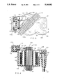
- FIG. 3 shows a top plan view of a modified ignition coil, generally designated as 100, while FIG. 4 shows a sectional elevation view through the modified ignition coil 100, taken through the line A--A in FIG. 3.
- the modified ignition coil 100 includes a standard laminated ferromagnetic core having an upper rectangular member 102 contacting a lower E-shaped member 104.
- the lower E-shaped member 104 has its two outer legs 104a and 104c, and central leg 104b extending upwardly, as indicated by the dotted lines designating the hidden surfaces
- a primary winding 106 of approximately 90 turns is continuously wrapped around a primary winding tube 108, which in then inserted over the central leg 104b of the E-shaped ferromagnetic core member 104.
- a secondary winding of approximately 8100 turns would normally be wound in a continuous fashion on a secondary bobbin to achieve a secondary to primary turns ratio of approximately 90:1, which is typical in conventional direct ignition systems.
- the continuously wound secondary bobbin would then be positioned concentrically around the primary winding tube 108 and the central leg 104b of the ferromagnetic core.
- the conventional continuously wound secondary bobbin is replaced with a segmented secondary bobbin 118 having a generally tubular cylindrical form that is axially segmented (or divided) into partitions by a series of annular flanges 120 extending in an outward radial direction.
- the segmented secondary bobbin 118 is preferably molded from a material having a high dielectric constant such polyphenylene oxide.
- the segmented secondary bobbin 118 is molded to directly replace the conventional continuous wound secondary bobbin to simplify the manufacture of the modified coil.
- the segmented secondary bobbin contains 11 partitions, for receiving turns of wire for the secondary winding 122 of the modified ignition coil 100.
- the secondary winding 122 is formed on the segmented secondary bobbin 118, by wrapping a predetermined number of turns into each partition, starting from one end and proceeding to each adjacent partition until reaching the opposite end of the segmented bobbin 118.
- a small slot may be provided in each flange 120 for passing the secondary wire from one partition to the next.
- the two end partitions receive approximately 293 turns, while each of the inner partitions receive approximately 585 turns. Consequently, the secondary winding 122 has approximately 5851 turns, giving the modified ignition coil 110 a secondary to primary turns ratio of 65:1.
- the primary winding tube 108, segmented secondary bobbin 118, and the ferromagnetic core members 102 and 104 are positioned within a coil housing 109, as shown in FIG. 4.
- the coil housing 109 is molded from a glass filled thermoplastic polyester resin.
- a potting material 107 such as a glass filled epoxy resin, is used to fill in the voids within the coil housing 109 and to hold the primary and secondary coil winding in the proper positions. This potting material 107 is shown partially removed in FIG. 4 for the purpose of illustration.
- Electrical leads 110 and 112 are used to connect the ends of the primary winding 106 to primary terminals 114 and 116, which are supported by upper and lower portions of a molded plastic terminal block, designated respectively as 113a and 113b.
- the primary terminals 114 and 116 provide the external coil connection points for the primary winding 106.
- the ends of the secondary winding 122 are connected to external secondary terminals 124 and 126 in the standard fashion, such as illustrated by electrical leads 127 and 128 shown in FIG. 4.
- the above described structure of the modified coil 100 is essentially identical with that of conventional direct ignition coils C1, C2, and C3, except for the reduced turns of the secondary winding 122 and segmented secondary bobbin 118. Reducing the turns of the secondary winding 122 increases the magnitude of the peak ignition current supplied by the modified coil 100, while use of the segmented secondary bobbin reduces the inter-winding capacitance of the secondary winding 122 to increase the peak voltage potential provided by the secondary winding 122.
- a large reflected voltage potential can appear across the primary winding 106 in modified coil 100, when the secondary winding is disconnected from either of its associated spark plugs (known as the open circuit fault condition).
- This large primary voltage potential can damage the coil 100 or the semiconductor switch within the DIS ignition module 78 used to control current flow through the primary winding 106.
- a metal oxide varistor 130 is connected in shunt with the primary winding 106 at the junction points 132 and 134 by welding or soldering.
- the metal oxide varistor 130 is a commercially available component, which is selected to break down at a predetermined potential (for example, 400 to 450 V), thereby limiting the reflected voltage potential across the primary winding and protecting its associated semiconductor switch, in the event that secondary winding 122 becomes open-circuited.
- a predetermined potential for example, 400 to 450 V
- FIG. 5 illustrates the difference between ignition current ignition current supplied by a convention DIS coil such as C1, C2, or C3, and the modified coil 100.
- the modified coil 100 increases the peak ignition current to approximately 110 mA, as compared to the 50 to 60 mA supplied by the conventional coil design.
- the preferred embodiment utilizes the modified ignition coil 100, as described above, as a replacement for each of the conventional direct ignition coils C1, C2, and C3.
- the quantity of fuel delivered to the engine during cold starting can be increased to establish combustible cylinder fuel vapor-air mixtures at lower temperatures without producing engine misfiring.
- engine cold starting performance can be further improved by scheduling the delivering fuel in an optimized fashion as the engine is cranked for starting. According to this scheduling, a large initial quantity of fuel, which is sufficient to rapidly form a combustible fuel vapor-air mixture in each engine cylinder, is delivered as engine cranking commences. As cranking continues, the quantity of delivered fuel is progressively decreased to maintain combustible fuel vapor-air mixtures in the engine cylinders, while restricting the accumulation of unvaporized fuel in each cylinder so as not to exceed a predetermined amount.
- This predetermined amount represents the maximum amount of unvaporized fuel that can accumulate in an engine cylinder without causing the cylinder spark plug to misfire due to wetting. Consequently, the predetermined amount of unvaporized fuel corresponds to the minimum resistive load that can appear in shunt with a spark plug arc gap, with the ignition current having a peak magnitude sufficient to achieve the break down voltage for the arc gap.
- FIG. 6 there is shown a graph of the computed fuel vapor-air equivalence ratio as a function of the injected or delivered fuel-air ratio for M-85(HVG) alcohol-based fuel at a temperature of -29° C. and normal atmospheric pressure. Data for the plot was computed according to an equilibrium model used by the Applicants, and described more fully in a publication "Cold Starts Using M-85 (85% Methanol): Coping with Low Fuel Volatility and Spark Plug Wetting," C. J. Dasch, N. D. Brinkman, and D. H. Hopper, SAE Paper No. 910865, 1991.
- the data in FIG. 6 indicates that an injected fuel-air ratio of approximately 4.0 is required to achieve a stoichiometric fuel vapor-air mixture for M-85(HVG) at the temperature of -29° C. with standard atmospheric pressure. This is approximately 30 times the mass of fuel that would be needed if all of the fuel were to vaporize, and about 10 times the mass of gasoline that would be needed to form a stoichiometric fuel vapor-air mixture at this temperature. Even though the temperatures and pressures in an engine cylinder are relatively higher than ambient, it has been found that the results predicted by the equilibrium model provide a reasonable estimate for the initial injected fuel-air ratio required to establish a combustible fuel vapor-air mixture in an engine cylinder.
- the equilibrium model as described in the above listed publication may be used to predict the fuel vapor-air equivalence ratio for an alcohol-based fuel other than M-85(HVG), given the composition of the fuel, the temperature, the pressure, and the injected air-fuel ratio.
- the optimum rate for decreasing the injected fuel-air ratio was found to be approximately an exponential function of the cumulative number of cranking revolutions, and more specifically, a 20% reduction in the injected fuel-air ratio for every engine cycle (or every two revolutions of the crankshaft in a four-stroke engine). This optimum rate for decreasing the injected fuel-air ratio during cranking enabled the largest quantity of fuel to be delivered at the initiation of cranking, without producing subsequent engine misfires.
- FIG. 7 illustrates a graph of the empirically determined optimized fueling schedule (assuming 100% engine volumetric efficiency) for an engine operating on M-85(HVG) fuel at -29° C. and standard atmospheric pressure, when the engine is furnished with an ignition system capable of supplying each cylinder spark plug with a peak ignition current of approximately 100 mA.
- This fueling schedule provided the fastest cylinder first-firing during cranking, without overly wetting the spark plugs to cause subsequent rich misfires (i.e. reducing the resistive loading across the spark plug gaps to the point where the peak ignition current is no longer sufficient to achieve the break down voltage of the arc gaps).
- the scheduled initial fuel-air ratio decreases, but the exponential rate of decreasing the fuel-air ratio with cranking revolutions remains the same.
- the optimum fueling schedules may change for different types of engines and/or different alcohol-based fuels, but these schedules can be empirically determined as set for above.
- the cold starting performance of an engine fueled with an alcohol-gasoline mixture can be enhanced in accordance with the present invention by: (1) deriving an indication of the engine temperature; (2) deriving an indication of the relative proportion of alcohol to gasoline in the fuel mixture; (3) deriving an indication of the cumulative number of engine revolutions during cranking; (4) delivering a scheduled quantity of fuel to the engine, as the engine is cranked for starting, where the scheduled quantity of fuel is determined as a function of the derived indications for the engine temperature, the relative proportion of alcohol to gasoline in the fuel mixture, and the cumulative number of cranking engine revolutions such that a combustible fuel vapor-air mixture is established in each engine cylinder, while the accumulation of unvaporized fuel in each cylinder is restricted so as not to exceed a predetermined amount; and (5) providing for each cylinder spark plug an ignition current having a magnitude sufficient to effectuate voltage break down across each spark plug arc gap, when the arc gap is resistively loaded due to wetting in accordance with the predetermined amount of accumulated un
- FIGS. 8A-B illustrate a simplified flow diagram representative of the steps executed by the electronic control unit 30 of FIG. 1, when scheduling the delivery of fuel to engine 10 during cold starting in accordance with the present invention.
- the electronic control unit 30 When the ignition switch 42 is rotated to start engine 10, the electronic control unit 30 is energized, and all of the internal counters, flags, registers, and timers are appropriately initialized. Thereafter, as is well known in the engine control art, the electronic control unit 30 continuously executes a main looped engine control program stored in read only memory.
- 8A-B is entered when engine 10 is cranked for starting, and is bypassed by the main engine control program, whenever the engine rotational speed exceeds a predetermined value (for example, 800 RPM), where the engine is considered to be running.
- the electronic control unit 30 determines the engine rotational speed from the REF input signal, as for example, by counting the number of pulses that occur during a fixed interval of time.
- the CRANKING FUEL ROUTINE is entered at point 200 and passes to step 202, where the relative proportion of alcohol to gasoline in the fuel mixture is determined by reading the value of the fuel composition signal ALC % provided by the fuel composition sensor 34. Thereafter, routine proceeds to step 204.
- an indication of the engine temperature is derived by reading the value of the TEMP input signal provided by the engine coolant temperature sensor 32. The program then passes to step 206.
- CALTEMP a predetermined value designated as CALTEMP
- an ALCOHOL COLD START FLAG is set to indicate that conditions require that fuel be delivered to the engine in accordance with the principles of the present invention to assure cold starting of the engine (i.e. ALC % >71% and TEMP ⁇ -15° C.).
- step 208 If the program passes to step 208 from either of steps 206 or 210, the ALCOHOL COLD START FLAG is reset to indicate that conditions do not exist for scheduling the delivery of fuel to the engine in accordance with the present invention.
- the base fuel pulse width T B for the engine fuel injectors (typically in units of milliseconds per engine revolution) is derived from a lookup table as a function of the engine temperature TEMP and the fuel composition ALC %.
- Other conventional corrections to the base fuel pulse width T B may also be made at this step in the routine.
- cranking revolutions the cumulative number of complete engine revolutions since the start of cranking. This may be accomplished within the ECU 30 by counting the the total number of pulses in the REF signal that occur after the initiation of cranking, and dividing that total by the number of reference pulses occurring during a single revolution of the engine crankshaft (three in this case).
- step 2108 a decision is required as to whether the ALCOHOL COLD START FLAG has been set or reset. If the ALCOHOL COLD START FLAG is set, the program proceeds to step 220, where a value for an alcohol cold start multiplier M A is obtained from a lookup table based upon the number of cranking revolutions determined at step 216. Next at step 222, a new value for the base fuel pulse width is obtained by multiplying the current value of T B by the alcohol cold start multiplier M A .
- step 2128 if the ALCOHOL COLD START FLAG is not set, or has been reset, the routine proceeds to step 224, where a value for a standard gasoline multiplier M G is obtained from a different lookup table, again based upon the number of cranking revolutions. Then at the next step 226, the current value for the base fuel pulse width T B is multiplied by the value of M G to obtain the new value for T B
- step 222 or 224 the program proceeds to step 228.
- the current value of the fuel pulse width is examined to determine whether it exceeds a maximum allowable value MAX. If T B is greater than MAX at step 228, the program proceeds to step 230, where T B is set equal to the value of MAX, before passing to step 232. If TB is not greater than MAX at step 228, the program proceeds directly to step 232, without passing through step 230.
- the value of MAX represents the practical upper limit of time available for injection per engine revolution (approximately 512 milliseconds for the engine 10 in the present embodiment).
- step 232 the current value for the fuel pulse width T B is stored in the random access memory of ECU 30, and is used in the main looped control program for setting the pulse width of the FUEL PULSE signal directed to each engine fuel injector.
- Typical values for the lookup tables containing the standard gasoline and alcohol cold start multipliers as a function of cranking revolutions are graphically illustrated in FIG. 9.
- the values for the standard gasoline multiplier M G are those conventionally used for starting engine 10.
- the values for the alcohol cold start multiplier M A are selected to approximately achieve the optimum rate of decrease in fuel delivery, in accordance with the present invention, as the engine is cranked for starting. Note that although the quantity of air delivered to the engine is relatively constant during cranking, the cold start multiplier does not decrease at the optimized exponential rate of 20% for every cycle of the engine. This is because the multiplier has been adjusted to account for the reduction in fuel flow from an electric fuel pump (not shown), which delivers the fuel to the engine fuel injectors.
- FIG. 7 Shown in FIG. 7 is a plot of the actual injected fuel-air ratio (at -29° C.) that was achieved in a production six-cylinder, 3.1 liter engine having the above described embodiment of the present invention, for comparison with the optimized schedule for the injected fuel-air ratio. Note that although it was possible to substantially achieve the optimum rate of decrease for the actual injected fuel-air ratio (20% per two cranking revolutions) in the production engine, it was not possible to attain the called for initial fuel-air ratio of approximately 5.0 at the start of cranking.
- a fuel composition sensor 34 was utilized to provide information related to the composition of the alcohol-based fuel delivered to engine 10. If the composition of the alcohol-based fuel is known and remains fixed for the engine, then the fuel composition sensor would not be required. In this case, steps 202 and 206 of the CRANKING FUEL ROUTINE of FIG. 8A could be removed, and the value for the base fuel pulse width T B (found at step 214) could be looked up as a function of engine temperature alone, since the fuel composition would remain fixed.
- the present invention is applicable to engines having ignition systems with distributors. Such a system would require only a single ignition coil having the above described modifications for increasing the peak ignition current. As is well known, one end of the secondary winding of the modified coil would be connected to the distributor rotor with the other end of the secondary winding connected to a ground point on the vehicle.
Abstract
Description
I.sub.s >V.sub.bd /R.sub.s.
Claims (21)
Priority Applications (1)
| Application Number | Priority Date | Filing Date | Title |
|---|---|---|---|
| US07/750,357 US5146882A (en) | 1991-08-27 | 1991-08-27 | Method and apparatus for cold starting a spark ignited internal combustion engine fueled with an alcohol-based fuel mixture |
Applications Claiming Priority (1)
| Application Number | Priority Date | Filing Date | Title |
|---|---|---|---|
| US07/750,357 US5146882A (en) | 1991-08-27 | 1991-08-27 | Method and apparatus for cold starting a spark ignited internal combustion engine fueled with an alcohol-based fuel mixture |
Publications (1)
| Publication Number | Publication Date |
|---|---|
| US5146882A true US5146882A (en) | 1992-09-15 |
Family
ID=25017539
Family Applications (1)
| Application Number | Title | Priority Date | Filing Date |
|---|---|---|---|
| US07/750,357 Expired - Lifetime US5146882A (en) | 1991-08-27 | 1991-08-27 | Method and apparatus for cold starting a spark ignited internal combustion engine fueled with an alcohol-based fuel mixture |
Country Status (1)
| Country | Link |
|---|---|
| US (1) | US5146882A (en) |
Cited By (24)
| Publication number | Priority date | Publication date | Assignee | Title |
|---|---|---|---|---|
| US5220895A (en) * | 1992-11-16 | 1993-06-22 | Ford Motor Company | Method and system for modifying a control signal for a fuel injector of a fuel delivery system |
| US5365917A (en) * | 1993-05-04 | 1994-11-22 | Chrysler Corporation | Hot soak for a flexible fuel compensation system |
| US5479817A (en) * | 1992-07-28 | 1996-01-02 | Ngk Spark Plug Co., Ltd. | Spark plug with built-in pressure sensor |
| US5515280A (en) * | 1992-01-22 | 1996-05-07 | Mitsubishi Denki Kabushiki Kaisha | Electronic control device for a multi-fuel internal combustion engine |
| US5697352A (en) * | 1995-04-24 | 1997-12-16 | Mitsubishi Denki Kabushiki Kaisha | Ignition apparatus for internal combustion engine |
| US6044824A (en) * | 1998-01-29 | 2000-04-04 | Mazda Motor Corporation | Fuel control unit and fuel injection control method for multi-cylinder engine |
| US6215385B1 (en) | 1999-11-12 | 2001-04-10 | Delphi Technologies, Inc. | Ignition coil with primary winding outside of secondary winding |
| US6276472B1 (en) * | 1998-04-01 | 2001-08-21 | Denso Corporation | Control system for hybrid vehicle |
| US6360726B1 (en) * | 2000-07-31 | 2002-03-26 | General Motors Corporation | Fuel volatility detection and compensation during cold engine start |
| US6502550B1 (en) | 2002-02-05 | 2003-01-07 | Ford Global Technologies, Inc. | Gaseous fueled engine system and method |
| US6763807B1 (en) | 1997-11-28 | 2004-07-20 | Clean Fuel Technology, Inc. | Apparatus and method for controlling a fuel injector assembly of an internal combustion engine during cold operation thereof |
| US20040244779A1 (en) * | 2003-06-09 | 2004-12-09 | Woo Jik Lee | Engine start control system and a method thereof |
| US6845764B1 (en) * | 2004-01-08 | 2005-01-25 | Delphi Technologies, Inc. | Ignition apparatus with secondary winding having reduced breakdown failures |
| US20090114188A1 (en) * | 2007-11-07 | 2009-05-07 | Ford Global Technologies, Llc | Ignition Energy Control for Mixed Fuel Engine |
| US20090293828A1 (en) * | 2008-05-27 | 2009-12-03 | Briggs & Stratton Corporation | Engine with an automatic choke and method of operating an automatic choke for an engine |
| CN102155317A (en) * | 2011-04-22 | 2011-08-17 | 奇瑞汽车股份有限公司 | Air-fuel ratio control method for methyl alcohol flexible fuel engine |
| US20120203444A1 (en) * | 2011-02-08 | 2012-08-09 | Denso Corporation | Startup control device for direct-injection internal combustion engine |
| US20130073190A1 (en) * | 2011-09-21 | 2013-03-21 | Honda Motor Co., Ltd. | Engine Start Up Control For A Motor Vehicle |
| US20140278006A1 (en) * | 2013-03-15 | 2014-09-18 | Honda Motor Co., Ltd. | Method for controlling an amount of fuel and vehicle including same |
| WO2014191811A1 (en) * | 2013-05-30 | 2014-12-04 | Toyota Jidosha Kabushiki Kaisha | Fuel injection control system of internal combustion engine |
| US20150142297A1 (en) * | 2013-11-18 | 2015-05-21 | Toyota Jidosha Kabushiki Kaisha | Control system for internal combustion engine of vehicle |
| US20180266350A1 (en) * | 2017-03-17 | 2018-09-20 | Ford Global Technologies, Llc | Method and system for engine cold-start |
| WO2018189200A1 (en) * | 2017-04-12 | 2018-10-18 | Continental Automotive Gmbh | Method and device for starting an internal combustion engine having high alcohol content in the fuel |
| US20190277242A1 (en) * | 2018-03-07 | 2019-09-12 | Toyota Jidosha Kabushiki Kaisha | Control device of internal combustion engine |
Citations (8)
| Publication number | Priority date | Publication date | Assignee | Title |
|---|---|---|---|---|
| US3972315A (en) * | 1974-10-21 | 1976-08-03 | General Motors Corporation | Dual action internal combustion engine ignition system |
| US4703732A (en) * | 1986-02-07 | 1987-11-03 | Ford Motor Company | Spark timing control of multiple fuel engine |
| US4706630A (en) * | 1986-02-07 | 1987-11-17 | Ford Motor Company | Control system for engine operation using two fuels of different volatility |
| US4711226A (en) * | 1987-01-21 | 1987-12-08 | General Motors Corporation | Internal combustion engine ignition system |
| US4750467A (en) * | 1986-09-11 | 1988-06-14 | General Motors Corporation | Internal combustion engine ignition system |
| US4893105A (en) * | 1987-06-30 | 1990-01-09 | Tdk Corporation | Transformer with tapered core |
| US4915084A (en) * | 1988-11-08 | 1990-04-10 | General Motors Corporation | Combustion engine with multi-fuel capability |
| US4971051A (en) * | 1987-07-13 | 1990-11-20 | Toffolon Norman R | Pneumatic cushion and seal |
-
1991
- 1991-08-27 US US07/750,357 patent/US5146882A/en not_active Expired - Lifetime
Patent Citations (8)
| Publication number | Priority date | Publication date | Assignee | Title |
|---|---|---|---|---|
| US3972315A (en) * | 1974-10-21 | 1976-08-03 | General Motors Corporation | Dual action internal combustion engine ignition system |
| US4703732A (en) * | 1986-02-07 | 1987-11-03 | Ford Motor Company | Spark timing control of multiple fuel engine |
| US4706630A (en) * | 1986-02-07 | 1987-11-17 | Ford Motor Company | Control system for engine operation using two fuels of different volatility |
| US4750467A (en) * | 1986-09-11 | 1988-06-14 | General Motors Corporation | Internal combustion engine ignition system |
| US4711226A (en) * | 1987-01-21 | 1987-12-08 | General Motors Corporation | Internal combustion engine ignition system |
| US4893105A (en) * | 1987-06-30 | 1990-01-09 | Tdk Corporation | Transformer with tapered core |
| US4971051A (en) * | 1987-07-13 | 1990-11-20 | Toffolon Norman R | Pneumatic cushion and seal |
| US4915084A (en) * | 1988-11-08 | 1990-04-10 | General Motors Corporation | Combustion engine with multi-fuel capability |
Non-Patent Citations (4)
| Title |
|---|
| "Capacitive Discharge/Inductive Ignition System," disclosed by Daniel H. Hopper, Research Disclosure No. 28035, Aug. 1987. |
| "Cold Starts Using M-85 (85% Methanol): Coping with Low Fuel Volatility and Spark Plug Wetting," C. J. Dasch, N. H. Brinkman, and D. H. Hopper, SAE Paper No. 910865, 1991. (Feb. 25-Mar. 1). |
| Capacitive Discharge/Inductive Ignition System, disclosed by Daniel H. Hopper, Research Disclosure No. 28035, Aug. 1987. * |
| Cold Starts Using M 85 (85% Methanol): Coping with Low Fuel Volatility and Spark Plug Wetting, C. J. Dasch, N. H. Brinkman, and D. H. Hopper, SAE Paper No. 910865, 1991. (Feb. 25 Mar. 1). * |
Cited By (41)
| Publication number | Priority date | Publication date | Assignee | Title |
|---|---|---|---|---|
| US5515280A (en) * | 1992-01-22 | 1996-05-07 | Mitsubishi Denki Kabushiki Kaisha | Electronic control device for a multi-fuel internal combustion engine |
| US5479817A (en) * | 1992-07-28 | 1996-01-02 | Ngk Spark Plug Co., Ltd. | Spark plug with built-in pressure sensor |
| US5220895A (en) * | 1992-11-16 | 1993-06-22 | Ford Motor Company | Method and system for modifying a control signal for a fuel injector of a fuel delivery system |
| US5365917A (en) * | 1993-05-04 | 1994-11-22 | Chrysler Corporation | Hot soak for a flexible fuel compensation system |
| US5697352A (en) * | 1995-04-24 | 1997-12-16 | Mitsubishi Denki Kabushiki Kaisha | Ignition apparatus for internal combustion engine |
| US6763807B1 (en) | 1997-11-28 | 2004-07-20 | Clean Fuel Technology, Inc. | Apparatus and method for controlling a fuel injector assembly of an internal combustion engine during cold operation thereof |
| US6044824A (en) * | 1998-01-29 | 2000-04-04 | Mazda Motor Corporation | Fuel control unit and fuel injection control method for multi-cylinder engine |
| US6276472B1 (en) * | 1998-04-01 | 2001-08-21 | Denso Corporation | Control system for hybrid vehicle |
| US6382335B2 (en) | 1998-04-01 | 2002-05-07 | Denso Corporation | Control system for hybrid vehicle |
| US6215385B1 (en) | 1999-11-12 | 2001-04-10 | Delphi Technologies, Inc. | Ignition coil with primary winding outside of secondary winding |
| US6360726B1 (en) * | 2000-07-31 | 2002-03-26 | General Motors Corporation | Fuel volatility detection and compensation during cold engine start |
| US6502550B1 (en) | 2002-02-05 | 2003-01-07 | Ford Global Technologies, Inc. | Gaseous fueled engine system and method |
| US20040244779A1 (en) * | 2003-06-09 | 2004-12-09 | Woo Jik Lee | Engine start control system and a method thereof |
| US7040296B2 (en) * | 2003-06-09 | 2006-05-09 | Hyundai Motor Company | Engine start control system and a method thereof |
| US6845764B1 (en) * | 2004-01-08 | 2005-01-25 | Delphi Technologies, Inc. | Ignition apparatus with secondary winding having reduced breakdown failures |
| US20090114188A1 (en) * | 2007-11-07 | 2009-05-07 | Ford Global Technologies, Llc | Ignition Energy Control for Mixed Fuel Engine |
| US9027531B2 (en) | 2007-11-07 | 2015-05-12 | Ford Global Technologies, Llc | Ignition energy control for mixed fuel engine |
| US8584650B2 (en) * | 2007-11-07 | 2013-11-19 | Ford Global Technologies, Llc | Ignition energy control for mixed fuel engine |
| US20090293828A1 (en) * | 2008-05-27 | 2009-12-03 | Briggs & Stratton Corporation | Engine with an automatic choke and method of operating an automatic choke for an engine |
| US20090299614A1 (en) * | 2008-05-27 | 2009-12-03 | Briggs & Stratton Corporation | Engine with an automatic choke and method of operating an automatic choke for an engine |
| US8219305B2 (en) | 2008-05-27 | 2012-07-10 | Briggs & Stratton Corporation | Engine with an automatic choke and method of operating an automatic choke for an engine |
| US8434445B2 (en) | 2008-05-27 | 2013-05-07 | Briggs & Stratton Corporation | Engine with an automatic choke and method of operating an automatic choke for an engine |
| US8434444B2 (en) | 2008-05-27 | 2013-05-07 | Briggs & Stratton Corporation | Engine with an automatic choke and method of operating an automatic choke for an engine |
| US20120203444A1 (en) * | 2011-02-08 | 2012-08-09 | Denso Corporation | Startup control device for direct-injection internal combustion engine |
| CN102155317A (en) * | 2011-04-22 | 2011-08-17 | 奇瑞汽车股份有限公司 | Air-fuel ratio control method for methyl alcohol flexible fuel engine |
| CN102155317B (en) * | 2011-04-22 | 2013-06-12 | 奇瑞汽车股份有限公司 | Air-fuel ratio control method for methyl alcohol flexible fuel engine |
| US20130073190A1 (en) * | 2011-09-21 | 2013-03-21 | Honda Motor Co., Ltd. | Engine Start Up Control For A Motor Vehicle |
| US20140278006A1 (en) * | 2013-03-15 | 2014-09-18 | Honda Motor Co., Ltd. | Method for controlling an amount of fuel and vehicle including same |
| US9638117B2 (en) * | 2013-03-15 | 2017-05-02 | Honda Motor Co., Ltd. | Method for controlling an amount of fuel and vehicle including same |
| US20160115889A1 (en) * | 2013-05-30 | 2016-04-28 | Toyota Jidosha Kabushiki Kaisha | Fuel injection control system of internal combustion engine |
| CN105264205A (en) * | 2013-05-30 | 2016-01-20 | 丰田自动车株式会社 | Fuel injection control system of internal combustion engine |
| JP2014231799A (en) * | 2013-05-30 | 2014-12-11 | トヨタ自動車株式会社 | Fuel injection control device for internal combustion engine |
| WO2014191811A1 (en) * | 2013-05-30 | 2014-12-04 | Toyota Jidosha Kabushiki Kaisha | Fuel injection control system of internal combustion engine |
| US20150142297A1 (en) * | 2013-11-18 | 2015-05-21 | Toyota Jidosha Kabushiki Kaisha | Control system for internal combustion engine of vehicle |
| US9856816B2 (en) * | 2013-11-18 | 2018-01-02 | Toyota Jidosha Kabushiki Kaisha | Control system for internal combustion engine of vehicle |
| US20180266350A1 (en) * | 2017-03-17 | 2018-09-20 | Ford Global Technologies, Llc | Method and system for engine cold-start |
| CN108626008A (en) * | 2017-03-17 | 2018-10-09 | 福特环球技术公司 | Method and system for engine cold starting |
| US10550783B2 (en) * | 2017-03-17 | 2020-02-04 | Ford Global Technologies, Llc | Method and system for engine cold-start |
| WO2018189200A1 (en) * | 2017-04-12 | 2018-10-18 | Continental Automotive Gmbh | Method and device for starting an internal combustion engine having high alcohol content in the fuel |
| US11060498B2 (en) | 2017-04-12 | 2021-07-13 | Vitesco Technologies GmbH | Method and device for starting an internal combustion engine having high alcohol content in the fuel |
| US20190277242A1 (en) * | 2018-03-07 | 2019-09-12 | Toyota Jidosha Kabushiki Kaisha | Control device of internal combustion engine |
Similar Documents
| Publication | Publication Date | Title |
|---|---|---|
| US5146882A (en) | Method and apparatus for cold starting a spark ignited internal combustion engine fueled with an alcohol-based fuel mixture | |
| US5333593A (en) | Energy-on-demand ignition coil | |
| CN105089903B (en) | The method and system of igniter motor control | |
| WO2009078235A1 (en) | Internal combustion engine controller | |
| RU2669112C1 (en) | Engine fuel supply method and device | |
| US20070028881A1 (en) | Supplementary fuel supply for a carbureted engine | |
| Toepel et al. | Development of Detroit Diesel Allison 6V-92TA methanol fueled coach engine | |
| CN107407216A (en) | Engine control strategy | |
| GB2257749A (en) | Control at starting of a mixed fuel engine | |
| US4143621A (en) | Fuel injection system with augmented temperature sensitive fuel enrichment for transient engine loads | |
| US6848421B1 (en) | Engine control method and apparatus using ion sense combustion monitoring | |
| US9797363B2 (en) | Control apparatus for an internal combustion engine | |
| US5488940A (en) | Ignition system for internal combustion engines | |
| JPS6342115B2 (en) | ||
| Johnston et al. | Programmable energy ignition system for engine optimization | |
| JP2002543326A (en) | Method and system for starting a combustion engine | |
| EP0075872A2 (en) | An ignition system for subsidiarily starting a diesel engine | |
| CN101922397B (en) | Ignition system of engine and control method thereof | |
| Fitzgerald | Pulsed Plasma lgnitor for Internal Combustion Engines | |
| EP0704621A2 (en) | Synchronisation device without a cam-position sensor for an internal combustion engine | |
| JP2525979B2 (en) | Gasoline engine combustion condition detector | |
| Gardiner et al. | Sub-zero cold starting of a port-injected M100 engine using plasma jet ignition and prompt EGR | |
| JP6246488B2 (en) | Air-fuel ratio control device for internal combustion engine using ion current | |
| CN115075969B (en) | Engine phase determination and control | |
| JP3726553B2 (en) | Internal combustion engine control method and apparatus |
Legal Events
| Date | Code | Title | Description |
|---|---|---|---|
| AS | Assignment |
Owner name: GENERAL MOTORS CORPORATION A CORPORATION OF DE, Free format text: ASSIGNMENT OF ASSIGNORS INTEREST.;ASSIGNORS:BRINKMAN, NORMAN D.;DASCH, CAMERON J.;ROCKWELL, LYNN A.;REEL/FRAME:005827/0117;SIGNING DATES FROM 19910816 TO 19910822 Owner name: DELCO ELECTRONICS CORPORATION A CORPORATION OF Free format text: ASSIGNMENT OF ASSIGNORS INTEREST.;ASSIGNOR:HOPPER, DANIEL H.;REEL/FRAME:005827/0120 Effective date: 19910826 |
|
| STCF | Information on status: patent grant |
Free format text: PATENTED CASE |
|
| FEPP | Fee payment procedure |
Free format text: PAYOR NUMBER ASSIGNED (ORIGINAL EVENT CODE: ASPN); ENTITY STATUS OF PATENT OWNER: LARGE ENTITY |
|
| FPAY | Fee payment |
Year of fee payment: 4 |
|
| FPAY | Fee payment |
Year of fee payment: 8 |
|
| FPAY | Fee payment |
Year of fee payment: 12 |
|
| AS | Assignment |
Owner name: GM GLOBAL TECHNOLOGY OPERATIONS, INC., MICHIGAN Free format text: ASSIGNMENT OF ASSIGNORS INTEREST;ASSIGNOR:GENERAL MOTORS CORPORATION;REEL/FRAME:022102/0533 Effective date: 20050119 Owner name: GM GLOBAL TECHNOLOGY OPERATIONS, INC.,MICHIGAN Free format text: ASSIGNMENT OF ASSIGNORS INTEREST;ASSIGNOR:GENERAL MOTORS CORPORATION;REEL/FRAME:022102/0533 Effective date: 20050119 |
|
| AS | Assignment |
Owner name: UNITED STATES DEPARTMENT OF THE TREASURY, DISTRICT Free format text: SECURITY AGREEMENT;ASSIGNOR:GM GLOBAL TECHNOLOGY OPERATIONS, INC.;REEL/FRAME:022201/0501 Effective date: 20081231 |
|
| AS | Assignment |
Owner name: CITICORP USA, INC. AS AGENT FOR HEDGE PRIORITY SEC Free format text: SECURITY AGREEMENT;ASSIGNOR:GM GLOBAL TECHNOLOGY OPERATIONS, INC.;REEL/FRAME:022556/0013 Effective date: 20090409 Owner name: CITICORP USA, INC. AS AGENT FOR BANK PRIORITY SECU Free format text: SECURITY AGREEMENT;ASSIGNOR:GM GLOBAL TECHNOLOGY OPERATIONS, INC.;REEL/FRAME:022556/0013 Effective date: 20090409 |
|
| AS | Assignment |
Owner name: GM GLOBAL TECHNOLOGY OPERATIONS, INC., MICHIGAN Free format text: RELEASE BY SECURED PARTY;ASSIGNOR:UNITED STATES DEPARTMENT OF THE TREASURY;REEL/FRAME:023238/0015 Effective date: 20090709 |
|
| XAS | Not any more in us assignment database |
Free format text: RELEASE BY SECURED PARTY;ASSIGNOR:UNITED STATES DEPARTMENT OF THE TREASURY;REEL/FRAME:023124/0383 |
|
| AS | Assignment |
Owner name: GM GLOBAL TECHNOLOGY OPERATIONS, INC., MICHIGAN Free format text: RELEASE BY SECURED PARTY;ASSIGNORS:CITICORP USA, INC. AS AGENT FOR BANK PRIORITY SECURED PARTIES;CITICORP USA, INC. AS AGENT FOR HEDGE PRIORITY SECURED PARTIES;REEL/FRAME:023127/0326 Effective date: 20090814 |
|
| AS | Assignment |
Owner name: UNITED STATES DEPARTMENT OF THE TREASURY, DISTRICT Free format text: SECURITY AGREEMENT;ASSIGNOR:GM GLOBAL TECHNOLOGY OPERATIONS, INC.;REEL/FRAME:023155/0922 Effective date: 20090710 |
|
| AS | Assignment |
Owner name: UAW RETIREE MEDICAL BENEFITS TRUST, MICHIGAN Free format text: SECURITY AGREEMENT;ASSIGNOR:GM GLOBAL TECHNOLOGY OPERATIONS, INC.;REEL/FRAME:023161/0864 Effective date: 20090710 |
|
| AS | Assignment |
Owner name: GM GLOBAL TECHNOLOGY OPERATIONS, INC., MICHIGAN Free format text: RELEASE BY SECURED PARTY;ASSIGNOR:UAW RETIREE MEDICAL BENEFITS TRUST;REEL/FRAME:025311/0680 Effective date: 20101026 Owner name: GM GLOBAL TECHNOLOGY OPERATIONS, INC., MICHIGAN Free format text: RELEASE BY SECURED PARTY;ASSIGNOR:UNITED STATES DEPARTMENT OF THE TREASURY;REEL/FRAME:025245/0273 Effective date: 20100420 |
|
| AS | Assignment |
Owner name: WILMINGTON TRUST COMPANY, DELAWARE Free format text: SECURITY AGREEMENT;ASSIGNOR:GM GLOBAL TECHNOLOGY OPERATIONS, INC.;REEL/FRAME:025327/0222 Effective date: 20101027 |