US5147542A - Manifold and manifold segment for tangential flow filtration apparatus - Google Patents
Manifold and manifold segment for tangential flow filtration apparatus Download PDFInfo
- Publication number
- US5147542A US5147542A US07/650,251 US65025191A US5147542A US 5147542 A US5147542 A US 5147542A US 65025191 A US65025191 A US 65025191A US 5147542 A US5147542 A US 5147542A
- Authority
- US
- United States
- Prior art keywords
- manifold
- filtrate
- outlet
- retentate
- segment
- Prior art date
- Legal status (The legal status is an assumption and is not a legal conclusion. Google has not performed a legal analysis and makes no representation as to the accuracy of the status listed.)
- Expired - Lifetime
Links
Images


Classifications
-
- B—PERFORMING OPERATIONS; TRANSPORTING
- B01—PHYSICAL OR CHEMICAL PROCESSES OR APPARATUS IN GENERAL
- B01D—SEPARATION
- B01D65/00—Accessories or auxiliary operations, in general, for separation processes or apparatus using semi-permeable membranes
-
- B—PERFORMING OPERATIONS; TRANSPORTING
- B01—PHYSICAL OR CHEMICAL PROCESSES OR APPARATUS IN GENERAL
- B01D—SEPARATION
- B01D63/00—Apparatus in general for separation processes using semi-permeable membranes
- B01D63/08—Flat membrane modules
- B01D63/082—Flat membrane modules comprising a stack of flat membranes
- B01D63/084—Flat membrane modules comprising a stack of flat membranes at least one flow duct intersecting the membranes
Definitions
- This invention relates to a manifold for a plurality of liquid filtration segments wherein filtration is effected by tangential flow of the liquid across a filter surface. More particularly, this invention relates to a manifold which permits stacking of a plurality of filtration segments wherein liquid is introduced and removed from the filtration module while eliminating the need for conduits for connecting the filtration segments.
- liquids primarily aqueous liquids have been filtered by tangential flow segments wherein a plurality of filters are stacked between two manifolds, one at the bottom of the stack and one at the top of the stack.
- the filtration module stack comprises a collection of one or more filtration modules and associated intermodule gaskets.
- the filters are separated by appropriate screens and liquid impervious layers to permit liquid flow, as well as filtrate and retentate flow into and from the stack.
- flow holes are provided through the layers within the stack. The holes are sealed appropriately to prevent admixture of filtrate with incoming liquid or retentate.
- the manifold s in each segment are designed so that filtrate is removed from both the top and bottom manifolds while incoming liquid is introduced into one manifold and retentate is removed from the second manifold.
- This manifold arrangement necessitates fittings to both manifold s in order to supply and remove liquid to and from the stacks. This is undesirable since additional manipulative steps for removing and connecting the fittings are required when it is desirable to replace the filtration elements forming the stack.
- the use of two manifolds to remove filtrate from the stack undesirably increases the filtrate volume retained within the stack.
- the requirement of two manifolds is undesirably expensive.
- a manifold apparatus which can be in fluid communication with any number of a plurality of filtration segments without the need for conduits external of the manifold .
- the manifold apparatus is comprised of one or a plurality of manifold segments which interconnect with one another to form a stack of manifold segments.
- a manifold segment comprises a single piece which holds filtration modules on each side and has internal conduits for the feed, filtrate and retentate. All manifold segments with the exception of the most downstream or most upstream manifold segment from the point of introducing incoming liquid must have a filtrate exit from both ends of the manifold segment.
- the most downstream or the most upstream manifold segment also can have filtrate exits from both of its ends.
- the retentate exit and incoming liquid inlet can be at the same ends of the manifold segments.
- the filtrate from filtration segments connected to the manifold is collected from all filtrate exits from the stack and the feed fluid is in fluid communication with retentate within the stack.
- the filtration segments are secured to the manifold in a manner so that filtrate is separated and collected without admixing with the feed or the retentate.
- FIG. 1 is an isometric view of the manifold apparatus of this invention in use.
- FIG. 2 is a side view of a manifold apparatus of this invention suitable for parallel feed to the manifold segments.
- FIG. 3 is a side view of a manifold apparatus of this invention suitable for serial feed to the manifold segments.
- FIG. 4 is a side view of a manifold apparatus of this invention which combines both serial and parallel feed to the manifold segments.
- FIG. 5 is a side view of a manifold apparatus of this invention which combines both serial and parallel feed to the manifold segments and which includes a manifold segment having one filtrate exit.
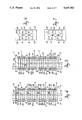
- FIG. 6 is a cross sectional view of the apparatus of FIG. 2 taken along line 6--6.
- FIG. 7 is a cross sectional view of the apparatus of FIG. 3 taken along line 7--7.
- FIG. 8 is an exploded view of a filtration module suitable for use with this invention.
- FIG. 9 illustrates the function of a filtration module Amplitude
- FIG. 10 is a side view of a manifold segment useful alone as a manifold of this invention.
- FIG. 11 is a side view of an alternative manifold segment useful alone as a manifold of this invention.
- FIG. 12 is a side view f an alternative manifold segment useful alone as a manifold of this invention.
- the manifold apparatus of this invention includes one or a plurality of center manifold segments 2, 4 and 6 connected together and which can be secured to manifold frame 8.
- Each end of the stack of manifold segments 2, 4 and 6 is provided with a fitting block 10 or 12 to provide suitable inlets and outlets to the manifold apparatus.
- a fluid feed inlet 14 and a filtrate outlet 16 are provided on fitting block 12, each of which are in fluid communication with suitable fluid storage means (not shown).
- a retentate outlet 18 and a filtrate outlet 20 are provided on fitting block 10, each of which are in fluid communication with a suitable fluid storage means (not shown).
- a plurality of filtration modules 22 are secured to manifold segments 2, 4 and 6 by means of a plate 19 and a plurality of compression assemblies 24 such as bolts.
- the manifold apparatus is provided with mainfold plate 30, 32 and 34.
- FIGS 2, and 6 the gaps between fitting blocks 10 and 12 and manifold segments 2, 4 and 6 are provided with conventional gasket means to effect desired sealing of filtrate from retentate and feed.
- a parallel feed and retentate arrangement is shown in FIG. 2.
- Fluid feed is introduced through inlet 14, feed channel 25a and into filtration modules 22 (FIG. 1) through fluid feed inlet means 26.
- Filtrate is removed from filtration modules 22 through filtrate outlet means 28 positioned on opposite sides of manifold segment 2, 4 and 6, filtrate outlet means 29, filtrate channel 21a and filtrate outlets 16 and 20.
- Outlet means 28 do not extend through manifold plates 30, 32 and 34 while outlet means 29 extend through manifold plates 30, 32 and 34 to fluid communication with filtrate outlets 16 and 20.
- Filtrate is removed from the manifold through filtrate outlets 16 and 20.
- the filtrate outlet means 28 and 29 are connected by slots 31 in manifold plates 30, 32 and 34.
- Retentate is removed from the filtration modules 22 through retentate outlet means 33 comprising holes in plates 30, 32 and 34, retentate channel 23 and retentate outlet 18.
- Holes 35 are provided in the manifold segments 2, 4 and 6 for bolts or tie rods to secure the filtration modules 22 to the manifold segments 2, 4 and 6.
- Tie rods 37 and nuts 39 are utilized to secure the manifold segments 2, 4 and 6 together.
- manifold segments 3, 5 and 7 are similar to the manifold segments 2, 4 and 6 of FIG. 2 except that only the feed passages 9 and retentate passages 11 pas only through a portion of the thickness of manifold segments 3, 5 and 7 thereby to effect a serial flow through the manifold segment rather than parallel flow.
- manifold apparatus utilizes manifold segments to effect both parallel and serial flow of feed through the manifold apparatus.
- Manifold segments 6, 7, 5 and 2 are provide in FIG. 4.
- Feed enters manifold segment 6 and an attached filtration module (not shown) through liquid inlet 14 and fluid inlet means 26.
- Filtrate is removed from manifold segment 6 through filtrate outlet means 29 and filtrate outlets 16 and 20.
- Retentate passes from manifold segment 6 through conduit 13 and into manifold segment 7 through conduit 23.
- Feed passes from manifold segment 6 from conduit 17 into manifold segment 7 through conduit 27.
- Feed passes from conduit 27 through feed inlet means 26 into a filtrate module (not shown).
- Filtrate is removed from manifold segment 7 through filtrate outlet means 29 and filtrate outlets 16 and 20.
- Retentate is removed from manifold segment 7 through retentate channel 23 and into feed channel 21 of manifold segment 5.
- feed and retentate pass in parallel flow through manifold segments 6 and 7.
- Retentate from manifold segment 7 becomes feed in segments 5 and 2 so that the feed in segments 5 and 2 is removed as retentate through conduits 23a and 25 and retentate outlet 18.
- Filtrate is removed through filtrate outlet means 29 and filtrate outlets 16 and 20.
- FIG. 5 The arrangement shown in FIG. 5 is the same as that shown in FIG. 4 except that there is only one filtrate outlet 16 rather than two filtrate outlets 16 and 20.
- End 16a outlet 16 is capped within manifold segment 1.
- the flow paths of feed and a retentate is the same as that described above for FIG. 4. Only one filtrate outlet 16 can be utilized in segment 1 so long as two filtrate outlet means are utilized in segments 5, 6 and 7. In the same manner, only one filtrate outlet can be utilized in the arrangements shown in FIGS. 2 and 3.
- a filtration module useful with the manifold of this invention is described.
- a filtration element 40 is positioned between manifold 47 and plate 19.
- Manifold 47 is provided with liquid inlet 14, filtrate outlets 16 and 20 and retentate outlet 18.
- the manifold 47 includes a plurality of feed inlet means 42 and a plurality of retentate outlet means 44.
- One set of filtrate outlet means 28 is provided on one end of the manifold 7 while a second set of filtrate outlet means 28 is provided on the opposite end of manifold 47.
- the filtrate outlet means 28 are connected to filtrate outlets 16 and 20 by filtrate conduit paths 46 and centrally located means 29.
- the paths 46 are of a size which permits filtrate to flow therethrough while avoiding sagging of a filtrate screen (not shown) into the paths 46 typically about 0.6 to 0.12 inch wide.
- the filtration element 40 includes holes 48 which communicate with liquid inlet means 42 and holes 50 which communicate with filtrate outlet means 28. As seen in FIG. 8, the filtrate side 52 of the filtration element 40 having mesh spacer 54 in contact therewith is exposed.
- the filtration segment 40 is also provided with holes 56 which communicate with retentate outlet means 44.
- the plate 19 serves as a seal for the top surface of the filtration element 40.
- the filtration element 40 includes a filtrate spacer 54, a filter layer 52a, a retentate spacer 60 and a filter layer 62 with a second filtrate spacer (not shown) and which can contact conduit paths 46.
- the liquid feed represented by arrow 58 passes through holes 48 in layer 62 into spacer 60.
- a portion of the liquid passes through spacer 60, as represented by arrow 64 and through filter 52 as represented by arrow 66.
- the remaining portion of the incoming liquid passes upwardly as represented by arrow 68, through holes 48 in filter layer 52a, holes 48 in filtrate spacer 54 and into the next adjacent filtration member (not shown) wherein it proceeds as described above with reference to filtration element 40.
- the filtrate passes into holes 50 and passes in a direction as shown by arrows 70 and 72 toward filtrate outlet means 28 (FIG. 8).
- the retentate passes across retentate spacer 60 as shown by arrows 64 and 65, through holes 56 and to retentate outlet means 44 (FIG. 8) in a direction as shown by arrow 78.
- the filtrate passes into holes 28, grooves 46, outlet means 29 (FIG. 8) toward filtrate outlets 16 and 20.
- the retentate passes through holes 44 and to rententate outlet 18.
- feed fluid is introduced into manifold segment 4 through feed inlets 14 and retentate removed from retentate outlets 18.
- Filtrate is removed from filtrate outlets 16 and 20.
- Feed enters filtration modules (not shown) through feed inlet means 26 from feed channel 25a and retentate is removed through retentate outlet means 33, retentate channel 23 and retentate outlet 18.
- feed fluid is introduced into manifold segment 3 through feed inlet 14 and retentate is removed from retentate outlet 18.
- Filtrate is removed from filtrate outlets 16 and 20 through feed inlet means 26 from feed channel 25 and retentate is removed from retentate outlet means 33, retentate channel 11 and rententate outlet 18.
- feed fluid is introduced into manifold segment 6 through feed inlets 14 and retentate is removed from retentate outlet 18.
- Filtrate is removed from filtrate outlets 16 and 20.
- Feed enters filtration modules (not shown) through feed inlet means 26 from channel 25a and retentate is removed through retentate outlet means 33, retentate channel 23 and retentate outlet 18.
- manifold segments shown in FIG. 10, 11 and 12 can be utilized as a manifold or with other manifold segments without the need for conduits connecting the manifold segments which conduits are external of the manifold segments.
Abstract
Description
Claims (11)
Priority Applications (5)
| Application Number | Priority Date | Filing Date | Title |
|---|---|---|---|
| US07/650,251 US5147542A (en) | 1991-02-04 | 1991-02-04 | Manifold and manifold segment for tangential flow filtration apparatus |
| US07/770,796 US5176828A (en) | 1991-02-04 | 1991-10-03 | Manifold segment stack with intermediate feed manifold |
| DE69215122T DE69215122T2 (en) | 1991-02-04 | 1992-01-21 | Distributor and distributor unit for a cross flow filter arrangement |
| EP92100949A EP0498211B1 (en) | 1991-02-04 | 1992-01-21 | Manifold and manifold segment for tangential flow filtration apparatus |
| JP04637292A JP3176974B2 (en) | 1991-02-04 | 1992-02-03 | Manifold device and manifold segment for interface flow type filter device |
Applications Claiming Priority (1)
| Application Number | Priority Date | Filing Date | Title |
|---|---|---|---|
| US07/650,251 US5147542A (en) | 1991-02-04 | 1991-02-04 | Manifold and manifold segment for tangential flow filtration apparatus |
Related Child Applications (1)
| Application Number | Title | Priority Date | Filing Date |
|---|---|---|---|
| US07/770,796 Continuation-In-Part US5176828A (en) | 1991-02-04 | 1991-10-03 | Manifold segment stack with intermediate feed manifold |
Publications (1)
| Publication Number | Publication Date |
|---|---|
| US5147542A true US5147542A (en) | 1992-09-15 |
Family
ID=24608125
Family Applications (1)
| Application Number | Title | Priority Date | Filing Date |
|---|---|---|---|
| US07/650,251 Expired - Lifetime US5147542A (en) | 1991-02-04 | 1991-02-04 | Manifold and manifold segment for tangential flow filtration apparatus |
Country Status (4)
| Country | Link |
|---|---|
| US (1) | US5147542A (en) |
| EP (1) | EP0498211B1 (en) |
| JP (1) | JP3176974B2 (en) |
| DE (1) | DE69215122T2 (en) |
Cited By (27)
| Publication number | Priority date | Publication date | Assignee | Title |
|---|---|---|---|---|
| WO1996039245A1 (en) * | 1995-06-06 | 1996-12-12 | Millipore Investment Holdings Limited | Manifold apparatus for tangential flow filtration apparatus |
| US6054051A (en) * | 1996-01-17 | 2000-04-25 | Genentech, Inc. | Tangential-flow filtration system |
| US20020175124A1 (en) * | 1999-09-14 | 2002-11-28 | Gabriel Tkacik | High-resolution virus removal methodology and filtration capsule useful therefor |
| US20030089664A1 (en) * | 2001-11-02 | 2003-05-15 | Phillips Michael W. | Membrane adsorber device |
| US20060060518A1 (en) * | 2004-09-21 | 2006-03-23 | Jeremy Perreault | Disposable tangential flow filtration device holder |
| US20070241048A1 (en) * | 2006-04-14 | 2007-10-18 | Hunt Stephen G | Disposable tangential flow filtration device holder |
| US20080135468A1 (en) * | 2006-12-11 | 2008-06-12 | Pall Corporation | Filtration assemblies and methods of installing filtration units in filtration assemblies |
| US20080135499A1 (en) * | 2006-12-11 | 2008-06-12 | Pall Corporation | Filtration assemblies and methods of maintaining compression of filtration units in filtration assemblies |
| US20080135500A1 (en) * | 2006-12-11 | 2008-06-12 | Pall Corporation | Filtration assemblies, filtration manifolds, filtration units, and methods of channeling permeate |
| US20080257813A1 (en) * | 2007-03-26 | 2008-10-23 | Millipore Corporation | Cassette-style filtration apparatus |
| US20110127203A1 (en) * | 2009-05-29 | 2011-06-02 | Millipore Corporation | Disposable Tangential Flow Filtration Liner With Sensor Mount |
| US20110174711A1 (en) * | 2009-08-04 | 2011-07-21 | Millipore Corporation | Self Contained Disposable Tangential Flow Filtration Liner |
| US20110215051A1 (en) * | 2005-12-29 | 2011-09-08 | Spf Innovations, Llc | Method and apparatus for the filtration of biological solutions |
| US20130256213A1 (en) * | 2010-12-16 | 2013-10-03 | Amiad Water Systems Ltd. | Filtration system and components there for |
| CN104023828A (en) * | 2011-12-20 | 2014-09-03 | 通用电气健康护理生物科学股份公司 | Distribution plate for crossflow filtration cassettes |
| US8919385B2 (en) | 2010-11-24 | 2014-12-30 | Pall Corporation | Manifold plates and fluid treatment arrangements including manifold plates |
| EP2957335A1 (en) | 2014-06-16 | 2015-12-23 | EMD Millipore Corporation | Single-pass filtration systems and processes |
| EP2957336A2 (en) | 2014-06-16 | 2015-12-23 | EMD Millipore Corporation | Methods for increasing the capacity of flow-through processes |
| WO2015195452A3 (en) * | 2014-06-16 | 2016-02-11 | Emd Millipore Corporation | Single-pass filtration systems and processes |
| WO2016033553A1 (en) * | 2014-08-29 | 2016-03-03 | Emd Millipore Corporation | Processes for filtering liquids using single pass tangential flow filtration systems and tangential flow filtration systems with recirculation of retentate |
| WO2016033546A1 (en) | 2014-08-29 | 2016-03-03 | Emd Millipore Corporation | Single pass tangential flow filtration systems and tangential flow filtration systems with recirculation of retentate |
| USD761381S1 (en) | 2014-12-18 | 2016-07-12 | Emd Millipore Corporation | Retentate plate |
| USD762811S1 (en) | 2014-12-18 | 2016-08-02 | Emd Millipore Corporation | Diverter plate |
| US20160339481A1 (en) * | 2007-06-27 | 2016-11-24 | Monsanto Technology Llc | Automated small object sorting systems and methods |
| US10399039B2 (en) | 2014-06-25 | 2019-09-03 | Emd Millipore Corporation | Compact spiral-wound filter elements, modules and systems |
| US20220395782A1 (en) * | 2021-06-14 | 2022-12-15 | John F. Connors, Jr. | Tangential flow filtration manifold |
| EP4144434A1 (en) | 2014-06-16 | 2023-03-08 | EMD Millipore Corporation | Single-pass filtration systems and processes |
Families Citing this family (9)
| Publication number | Priority date | Publication date | Assignee | Title |
|---|---|---|---|---|
| US5176828A (en) * | 1991-02-04 | 1993-01-05 | Millipore Corporation | Manifold segment stack with intermediate feed manifold |
| DE19850707C1 (en) * | 1998-11-04 | 2000-05-18 | Sartorius Gmbh | Distribution plate for crossflow cassette filtration devices |
| DE10000186C2 (en) * | 2000-01-05 | 2003-09-04 | Sartorius Gmbh | Device and system for crossflow filtration |
| DE102006009804B4 (en) * | 2006-03-01 | 2009-02-12 | Sartorius Stedim Biotech Gmbh | Cassette stack jig |
| US7959805B2 (en) | 2006-07-28 | 2011-06-14 | Millipore Corporation | Manifold adaptor plate for filtration apparatus |
| EP1946825A1 (en) * | 2006-12-11 | 2008-07-23 | Pall Corporation | Filtration assemblies and methods of maintaining compression of filtration units in filtration assemblies |
| FR2960160B1 (en) * | 2010-05-19 | 2012-08-17 | Millipore Corp | FLUID BOND BLOCK FOR FILTRATION DEVICE HAVING AT LEAST ONE FILTER CASSETTE |
| FR2960162B1 (en) | 2010-05-19 | 2012-08-17 | Millipore Corp | FILTRATION DEVICE WITH GAME OF AT LEAST ONE FILTERING CASSETTE |
| DE102015122261B3 (en) * | 2015-12-18 | 2017-01-12 | Sartorius Stedim Biotech Gmbh | Kassetteneinspannvorrichtung |
Citations (5)
| Publication number | Priority date | Publication date | Assignee | Title |
|---|---|---|---|---|
| US4212742A (en) * | 1978-05-25 | 1980-07-15 | United States Of America | Filtration apparatus for separating blood cell-containing liquid suspensions |
| US4261834A (en) * | 1978-05-18 | 1981-04-14 | Millipore Corporation | Device and process for removing pyrogens from aqueous solutions |
| US4310416A (en) * | 1977-08-19 | 1982-01-12 | Kuraray Company, Limited | Plate type fluid treatment apparatus |
| US4715955A (en) * | 1986-12-22 | 1987-12-29 | Filtron Technology Corp. | Ultrafiltration apparatus |
| US4849102A (en) * | 1988-05-31 | 1989-07-18 | Filtron Technology Corporation | Bidirectional ultrafiltration apparatus |
-
1991
- 1991-02-04 US US07/650,251 patent/US5147542A/en not_active Expired - Lifetime
-
1992
- 1992-01-21 DE DE69215122T patent/DE69215122T2/en not_active Expired - Lifetime
- 1992-01-21 EP EP92100949A patent/EP0498211B1/en not_active Expired - Lifetime
- 1992-02-03 JP JP04637292A patent/JP3176974B2/en not_active Expired - Lifetime
Patent Citations (5)
| Publication number | Priority date | Publication date | Assignee | Title |
|---|---|---|---|---|
| US4310416A (en) * | 1977-08-19 | 1982-01-12 | Kuraray Company, Limited | Plate type fluid treatment apparatus |
| US4261834A (en) * | 1978-05-18 | 1981-04-14 | Millipore Corporation | Device and process for removing pyrogens from aqueous solutions |
| US4212742A (en) * | 1978-05-25 | 1980-07-15 | United States Of America | Filtration apparatus for separating blood cell-containing liquid suspensions |
| US4715955A (en) * | 1986-12-22 | 1987-12-29 | Filtron Technology Corp. | Ultrafiltration apparatus |
| US4849102A (en) * | 1988-05-31 | 1989-07-18 | Filtron Technology Corporation | Bidirectional ultrafiltration apparatus |
Cited By (72)
| Publication number | Priority date | Publication date | Assignee | Title |
|---|---|---|---|---|
| WO1996039245A1 (en) * | 1995-06-06 | 1996-12-12 | Millipore Investment Holdings Limited | Manifold apparatus for tangential flow filtration apparatus |
| US5599447A (en) * | 1995-06-06 | 1997-02-04 | Millipore Investment Holdings Limited | Manifold apparatus for tangential flow filtration apparatus |
| US20030178367A1 (en) * | 1996-01-17 | 2003-09-25 | Van Reis Robert D. | Tangential-flow filtration system |
| US6926833B2 (en) | 1996-01-17 | 2005-08-09 | Genentech, Inc. | Tangential-flow filtration system |
| US6387270B1 (en) | 1996-01-17 | 2002-05-14 | Genentech, Inc. | Tangential-flow filtration system |
| US6054051A (en) * | 1996-01-17 | 2000-04-25 | Genentech, Inc. | Tangential-flow filtration system |
| US6555006B2 (en) | 1996-01-17 | 2003-04-29 | Genentech, Inc. | Tangential-flow filtration system |
| US6221249B1 (en) | 1996-01-17 | 2001-04-24 | Genentech, Inc. | Tangential-flow filtration system |
| US20060060519A1 (en) * | 1999-09-14 | 2006-03-23 | Gabriel Tkacik | High-resolution virus removal methodology and filtration capsule useful therefor |
| US7108791B2 (en) | 1999-09-14 | 2006-09-19 | Millipore Corporation | High-resolution virus removal methodology and filtration capsule useful therefor |
| US20020175124A1 (en) * | 1999-09-14 | 2002-11-28 | Gabriel Tkacik | High-resolution virus removal methodology and filtration capsule useful therefor |
| US20030089664A1 (en) * | 2001-11-02 | 2003-05-15 | Phillips Michael W. | Membrane adsorber device |
| US20060273008A1 (en) * | 2001-11-02 | 2006-12-07 | Phillips Michael W | Membrane adsorber device |
| US7281410B2 (en) | 2001-11-02 | 2007-10-16 | Millipore Corporation | Method for determining an effective peclet number for a membrane adsorber device |
| US7306727B2 (en) * | 2004-09-21 | 2007-12-11 | Millipore Corporation | Disposable tangential flow filtration device holder |
| US20060060518A1 (en) * | 2004-09-21 | 2006-03-23 | Jeremy Perreault | Disposable tangential flow filtration device holder |
| US8728315B2 (en) | 2005-12-29 | 2014-05-20 | Spf Innovations, Llc | Method and apparatus for the filtration of biological solutions |
| US8157999B2 (en) | 2005-12-29 | 2012-04-17 | Spf Innovations, Llc | Method and apparatus for the filtration of biological solutions |
| US9662614B2 (en) | 2005-12-29 | 2017-05-30 | Spf Innovations Llc | Method and apparatus for the filtration of biological solutions |
| US10421043B2 (en) | 2005-12-29 | 2019-09-24 | Spf Innovations, Llc | Method and apparatus for the filtration of biological solutions |
| US11007483B2 (en) | 2005-12-29 | 2021-05-18 | Spf Innovations, Llc | Method and apparatus for the filtration of biological solutions |
| US11633698B2 (en) | 2005-12-29 | 2023-04-25 | Spf Innovations, Llc | Method and apparatus for the filtration of biological solutions |
| US20110215051A1 (en) * | 2005-12-29 | 2011-09-08 | Spf Innovations, Llc | Method and apparatus for the filtration of biological solutions |
| US20070241048A1 (en) * | 2006-04-14 | 2007-10-18 | Hunt Stephen G | Disposable tangential flow filtration device holder |
| US9114366B2 (en) | 2006-04-14 | 2015-08-25 | Emd Millipore Corporation | Disposable tangential flow filtration device holder |
| US8177974B2 (en) | 2006-04-14 | 2012-05-15 | Emd Millipore Corporation | Disposable tangential flow filtration device holder |
| US7976705B2 (en) | 2006-12-11 | 2011-07-12 | Pall Corporation | Filtration assemblies and methods of installing filtration units in filtration assemblies |
| US20080135468A1 (en) * | 2006-12-11 | 2008-06-12 | Pall Corporation | Filtration assemblies and methods of installing filtration units in filtration assemblies |
| US20080135499A1 (en) * | 2006-12-11 | 2008-06-12 | Pall Corporation | Filtration assemblies and methods of maintaining compression of filtration units in filtration assemblies |
| US20080135500A1 (en) * | 2006-12-11 | 2008-06-12 | Pall Corporation | Filtration assemblies, filtration manifolds, filtration units, and methods of channeling permeate |
| US7918999B2 (en) | 2006-12-11 | 2011-04-05 | Pall Corporation | Filtration assemblies, filtration manifolds, filtration units, and methods of channeling permeate |
| US20080257813A1 (en) * | 2007-03-26 | 2008-10-23 | Millipore Corporation | Cassette-style filtration apparatus |
| US20160339481A1 (en) * | 2007-06-27 | 2016-11-24 | Monsanto Technology Llc | Automated small object sorting systems and methods |
| US20110127203A1 (en) * | 2009-05-29 | 2011-06-02 | Millipore Corporation | Disposable Tangential Flow Filtration Liner With Sensor Mount |
| US9289703B2 (en) | 2009-05-29 | 2016-03-22 | Emd Millipore Corporation | Disposable tangential flow filtration liner with sensor mount |
| US8454822B2 (en) | 2009-05-29 | 2013-06-04 | Emd Millipore Corporation | Disposable tangential flow filtration liner with sensor mount |
| US20110174711A1 (en) * | 2009-08-04 | 2011-07-21 | Millipore Corporation | Self Contained Disposable Tangential Flow Filtration Liner |
| US8919385B2 (en) | 2010-11-24 | 2014-12-30 | Pall Corporation | Manifold plates and fluid treatment arrangements including manifold plates |
| US20130256213A1 (en) * | 2010-12-16 | 2013-10-03 | Amiad Water Systems Ltd. | Filtration system and components there for |
| CN104023828A (en) * | 2011-12-20 | 2014-09-03 | 通用电气健康护理生物科学股份公司 | Distribution plate for crossflow filtration cassettes |
| CN104023828B (en) * | 2011-12-20 | 2017-09-26 | 通用电气健康护理生物科学股份公司 | Distribution plate for cross-flow filtration box |
| US9718028B2 (en) | 2011-12-20 | 2017-08-01 | General Electric Company | Distribution plate for crossflow filtration cassettes |
| WO2015195453A2 (en) | 2014-06-16 | 2015-12-23 | Emd Millipore Corporation | Methods for increasing the capacity of flow-through processes |
| WO2015195452A3 (en) * | 2014-06-16 | 2016-02-11 | Emd Millipore Corporation | Single-pass filtration systems and processes |
| EP2957335A1 (en) | 2014-06-16 | 2015-12-23 | EMD Millipore Corporation | Single-pass filtration systems and processes |
| US11617988B2 (en) | 2014-06-16 | 2023-04-04 | Emd Millipore Corporation | Single-pass filtration systems and processes |
| EP4144434A1 (en) | 2014-06-16 | 2023-03-08 | EMD Millipore Corporation | Single-pass filtration systems and processes |
| EP4122585A1 (en) | 2014-06-16 | 2023-01-25 | EMD Millipore Corporation | Methods for increasing the capacity of flow-through processes |
| US11040310B2 (en) | 2014-06-16 | 2021-06-22 | Emd Millipore Corporation | Single-pass filtration systems and processes |
| EP2957336A2 (en) | 2014-06-16 | 2015-12-23 | EMD Millipore Corporation | Methods for increasing the capacity of flow-through processes |
| EP3693080A1 (en) | 2014-06-16 | 2020-08-12 | EMD Millipore Corporation | Single-pass filtration systems and processes |
| US10207225B2 (en) | 2014-06-16 | 2019-02-19 | Emd Millipore Corporation | Single-pass filtration systems and processes |
| US10550148B2 (en) | 2014-06-16 | 2020-02-04 | Emd Millipore Corporation | Methods for increasing the capacity of flow-through processes |
| EP3527282A1 (en) | 2014-06-16 | 2019-08-21 | EMD Millipore Corporation | Methods for increasing the capacity of flow-through processes |
| US11311841B2 (en) | 2014-06-25 | 2022-04-26 | Emd Millipore Corp. | Compact spiral-wound filter elements, modules and systems |
| US10399039B2 (en) | 2014-06-25 | 2019-09-03 | Emd Millipore Corporation | Compact spiral-wound filter elements, modules and systems |
| WO2016033546A1 (en) | 2014-08-29 | 2016-03-03 | Emd Millipore Corporation | Single pass tangential flow filtration systems and tangential flow filtration systems with recirculation of retentate |
| WO2016033553A1 (en) * | 2014-08-29 | 2016-03-03 | Emd Millipore Corporation | Processes for filtering liquids using single pass tangential flow filtration systems and tangential flow filtration systems with recirculation of retentate |
| US10195550B2 (en) | 2014-08-29 | 2019-02-05 | Emd Millipore Corporation | Single pass tangential flow filtration systems and tangential flow filtration systems with recirculation of retentate |
| US11679349B2 (en) | 2014-08-29 | 2023-06-20 | Emd Millipore Corporation | Single pass tangential flow filtration systems and tangential flow filtration systems with recirculation of retentate |
| US11278827B2 (en) | 2014-08-29 | 2022-03-22 | Emd Millipore Corporation | Processes for filtering liquids using single pass tangential flow filtration systems and tangential flow filtration systems with recirculation of retentate |
| US11033839B2 (en) | 2014-08-29 | 2021-06-15 | Emd Millipore Corporation | Single pass tangential flow filtration systems and tangential flow filtration systems with recirculation of retentate |
| US10350518B2 (en) | 2014-08-29 | 2019-07-16 | Emd Millipore Corporation | Processes for filtering liquids using single pass tangential flow filtration systems and tangential flow filtration systems with recirculation of retentate |
| CN105745009A (en) * | 2014-08-29 | 2016-07-06 | Emd 密理博公司 | Single pass tangential flow filtration systems and tangential flow filtration systems with recirculation of retentate |
| CN105745009B (en) * | 2014-08-29 | 2018-09-28 | Emd 密理博公司 | The tangential flow filtration system of one way tangential flow filtration system and recycling with retentate |
| EP4147769A1 (en) | 2014-08-29 | 2023-03-15 | EMD Millipore Corporation | Processes for filtering liquids using single pass tangential flow filtration systems and tangential flow filtration systems with recirculation of retentate |
| USD762811S1 (en) | 2014-12-18 | 2016-08-02 | Emd Millipore Corporation | Diverter plate |
| USD857839S1 (en) | 2014-12-18 | 2019-08-27 | Emd Millipore Corporation | Retentate plate |
| USD811519S1 (en) | 2014-12-18 | 2018-02-27 | Emd Millipore Corporation | Retentate plate |
| USD761381S1 (en) | 2014-12-18 | 2016-07-12 | Emd Millipore Corporation | Retentate plate |
| USD912765S1 (en) | 2014-12-18 | 2021-03-09 | Emd Millipore Corporation | Retentate plate |
| US20220395782A1 (en) * | 2021-06-14 | 2022-12-15 | John F. Connors, Jr. | Tangential flow filtration manifold |
Also Published As
| Publication number | Publication date |
|---|---|
| EP0498211A1 (en) | 1992-08-12 |
| EP0498211B1 (en) | 1996-11-13 |
| JP3176974B2 (en) | 2001-06-18 |
| JPH06114213A (en) | 1994-04-26 |
| DE69215122D1 (en) | 1996-12-19 |
| DE69215122T2 (en) | 1997-04-10 |
Similar Documents
| Publication | Publication Date | Title |
|---|---|---|
| US5147542A (en) | Manifold and manifold segment for tangential flow filtration apparatus | |
| US5176828A (en) | Manifold segment stack with intermediate feed manifold | |
| US5096582A (en) | Tangential flow filtration apparatus | |
| US5599447A (en) | Manifold apparatus for tangential flow filtration apparatus | |
| US4735718A (en) | Multilayer membrane separator | |
| US4849102A (en) | Bidirectional ultrafiltration apparatus | |
| US4225439A (en) | Apparatus for selective separation of matter through semi-permeable membranes | |
| US6375700B1 (en) | Direct flow filter | |
| US7918999B2 (en) | Filtration assemblies, filtration manifolds, filtration units, and methods of channeling permeate | |
| US4801381A (en) | Ultrafiltration apparatus | |
| BR8505612A (en) | SET FOR THE SEPARATION OF LIQUID MIXTURES THROUGH PERVAPORATION | |
| US3534860A (en) | Pressure seal-manifold unit | |
| US5160433A (en) | Laboratory scale ultrafiltration apparatus | |
| US4997565A (en) | Laboratory scale ultrafiltration apparatus | |
| JPH059124B2 (en) | ||
| EP0344709A2 (en) | Cross-flow filtration module | |
| GB1341536A (en) | ||
| JP3251070B2 (en) | Manifold segment stack with intermediate feed manifold | |
| GB2146258A (en) | Divided-bed fluid filter | |
| EP0196392A2 (en) | Plural layer separator screen tangential flow filter device | |
| RU2033188C1 (en) | Multichamber membrane filter | |
| CN217795507U (en) | Laminated filter compatible with forward flow and tangential flow | |
| CN218871794U (en) | Filtering membrane package and filter equipment thereof | |
| JPH01143614A (en) | Multistage filter | |
| JP2917714B2 (en) | Filter |
Legal Events
| Date | Code | Title | Description |
|---|---|---|---|
| AS | Assignment |
Owner name: MILLIPORE CORPORATION, 80 ASHBY ROAD, BEDFORD, MAS Free format text: ASSIGNMENT OF ASSIGNORS INTEREST.;ASSIGNOR:PROULX, ANDREW;REEL/FRAME:005672/0380 Effective date: 19910201 |
|
| STCF | Information on status: patent grant |
Free format text: PATENTED CASE |
|
| AS | Assignment |
Owner name: MILLIPORE INVESTMENT HOLDINGS LTD., DELAWARE Free format text: ASSIGNMENT OF ASSIGNORS INTEREST;ASSIGNOR:MILLIPORE CORPORATION;REEL/FRAME:006862/0716 Effective date: 19931214 |
|
| FEPP | Fee payment procedure |
Free format text: PAYOR NUMBER ASSIGNED (ORIGINAL EVENT CODE: ASPN); ENTITY STATUS OF PATENT OWNER: LARGE ENTITY |
|
| FPAY | Fee payment |
Year of fee payment: 4 |
|
| FPAY | Fee payment |
Year of fee payment: 8 |
|
| AS | Assignment |
Owner name: MILLIPORE CORPORATION, MASSACHUSETTS Free format text: MERGER;ASSIGNOR:MILLIPORE INVESTMENT HOLDINGS LIMITED;REEL/FRAME:012025/0799 Effective date: 20010329 |
|
| FPAY | Fee payment |
Year of fee payment: 12 |