US5153776A - Wide angle zoom lens system - Google Patents
Wide angle zoom lens system Download PDFInfo
- Publication number
- US5153776A US5153776A US07/741,044 US74104491A US5153776A US 5153776 A US5153776 A US 5153776A US 74104491 A US74104491 A US 74104491A US 5153776 A US5153776 A US 5153776A
- Authority
- US
- United States
- Prior art keywords
- sub
- lens
- wide angle
- lens group
- negative
- Prior art date
- Legal status (The legal status is an assumption and is not a legal conclusion. Google has not performed a legal analysis and makes no representation as to the accuracy of the status listed.)
- Expired - Lifetime
Links
Images


Classifications
-
- G—PHYSICS
- G02—OPTICS
- G02B—OPTICAL ELEMENTS, SYSTEMS OR APPARATUS
- G02B15/00—Optical objectives with means for varying the magnification
- G02B15/14—Optical objectives with means for varying the magnification by axial movement of one or more lenses or groups of lenses relative to the image plane for continuously varying the equivalent focal length of the objective
- G02B15/143—Optical objectives with means for varying the magnification by axial movement of one or more lenses or groups of lenses relative to the image plane for continuously varying the equivalent focal length of the objective having three groups only
- G02B15/1435—Optical objectives with means for varying the magnification by axial movement of one or more lenses or groups of lenses relative to the image plane for continuously varying the equivalent focal length of the objective having three groups only the first group being negative
- G02B15/143503—Optical objectives with means for varying the magnification by axial movement of one or more lenses or groups of lenses relative to the image plane for continuously varying the equivalent focal length of the objective having three groups only the first group being negative arranged -+-
Definitions
- the present invention relates to a wide angle zoom lens system lending itself well fit for use with cameras which are limitless in terms of their back focal distances, like "lens shutter cameras” and, more particularly, to a ternary negative-positive-negative type of wide angle zoom lens system which has an extended zoom range toward the wide angle side so that it can have a field angle of 70° or more at the wide angle end and a zoom ratio of 3 or more.
- zoom lens systems have been known for use with the lens shutter cameras which are limitless in terms of their back focal distances, or other cameras.
- the binary positive-negative type of zoom lens systems are found to have a zoom ratio of at most 2.
- ternary zoom lens systems having a zoom ratio of about 3 which are represented by such a ternary positive-positive-negative type of zoom lens system as set forth in Japanese Patent Laid-Open Publication No. 63 (1988)-153511, such a ternary negative-positive-negative type of zoom lens system as described in Japanese Patent Laid-Open Publication No.
- Japanese Patent Laid-Open Publication No. 2(1990)-71220 proposes a zoom lens system which exceeds 3 in terms of zoom ratio and has a zoom ratio extended toward the wide angle side by reducing its focal length on the wide angle side.
- a problem with the binary type of zoom lens system is that when it is intended to extend the zoom ratio to about 3, there is an increase in variations of the magnification of the second lens group; much difficulty is encountered in correcting aberrations because of aberrational fluctuations increased by zooming.
- the zoom ratio it may be possible to extend the zoom ratio to about 3.
- the first lens group is of positive refracting power, as is the case with the positive-positive-negative or positive-negative-positive system, it is difficult to form a retrofocus design at the wide angle side.
- it is intended to extend the zoom ratio toward the wide angle side therefore, it is impossible to have sufficient back focal distance, thus causing the off-axial bundle of rays to pass through the 3rd lens group at a position far off the optical axis. This results in an increase in the diameter of the 3rd lens group and renders it difficult to correct off-axial aberrations.
- the ternary negative-positive-negative type of zoom lens system can have sufficient back focal distance at the wide angle side, because it is easy to obtain a retrofocus design at the wide angle side.
- a problem with this type is that difficulty is involved in obtaining a telephoto design at the telephoto side, thus giving rise to an increase in the overall length on the telephoto side.
- the zoom lens system referred to in the above-mentioned Japanese Patent Laid-Open Publication 2-37317--wherein the zoom ratio is extended by reducing the focal length at the wide angle side to 28.8 mm-- also presents a problem that it is increased in the number of lenses involved, with the resulting increase in the overall length at the telephoto side.
- an object of this invention is to solve the above-mentioned problems associated with the prior art by the provision of a ternary negative-positive-negative type of wide angle zoom lens system, which has an extended zoom range toward the wide angle side so that it can have a field angle of 70° or more at the wide angle end and a zoom ratio of 3 or more, is more reduced in the number of lenses involved and the overall length and more compact than this class of conventional zoom lens systems, and is much more improved in terms of aberrational performance.
- the above-mentioned object is well accomplished by providing a wide angle zoom lens system which is built up of, in order from the object side, a first lens group of negative refracting power, a second lens group of positive refracting power and a third lens group of negative refracting power, as can be best seen from FIGS. 1, 3 and 5, and in which both the air spaces between the 1st and 2nd lens groups and the 2nd and 3rd lens groups are narrowed when the power is varied from the wide angle side to the telephoto side, characterized by satisfying the following conditions:
- F W is the focal length of the overall system at the wide angle end
- F T is the focal length of the overall system at the telephoto end
- f 12T is the combined focal length of the 1st and 2nd lens groups at the telephoto end
- f 3 is the focal length of the 3rd lens group
- ⁇ 3W is the lateral magnification of the 3rd lens group at the wide angle end
- ⁇ 3T is the lateral magnification of the 3rd lens group at the telephoto end.
- an aperture stop is located before or after the 2nd lens groups such that it moves together with the 2nd lens group during zooming.
- Condition (1) concerns the overall length of the lens system at the telephoto end.
- a telephoto type of lens system built up of a front positive lens group defined by the 1st and 2nd lens groups and a rear negative lens group defined by the 3rd lens group.
- the shorter the combined focal length f 12T of the 1st and 2nd lens groups with respect to the focal length F T of the overall system the more enhanced the telephoto effect or, in other words, the more advantageously is the reduction in the overall length achieved.
- Too enhanced a telephoto effect causes that the focal length f 3 of the 3rd lens group is so shortened that difficulty will be involved in correcting aberrations, esp., correcting off-axial aberrations at the wide angle side.
- Condition (1) is provided as one requirement of this invention. At higher than the upper limit of 0.35 the overall length on the telephoto side will be too long to make the system compact, whereas at less than the lower limit of 0.1 difficulty will be encountered in correcting off-axial aberrations on the wide angle side in particular and in improving aberrational performance.
- Condition (2) is directed to the back focal distance of the lens system at the wide angle end. At higher than the upper limit of 2.0, it has a back focal distance that is longer than required and so is unpreferred for use with, e.g. a lens shutter camera; it becomes too long in the overall length at the wide angle end. At less than the lower limit of 1.0, it has a back focal distance so short that, as already mentioned in connection with the problems of the prior art, the 3rd lens group is increased in diameter and difficulty will be experienced in correcting off-axial aberrations.
- Condition (3) is provided for determining the rate of variable power of the 3rd lens group so as to obtain the required zoom ratio.
- the magnification shared by the 3rd lens group during zooming is so high that the amount of movement of the 3rd lens group by zooming is increased, rendering it difficult to design the associated lens barrel and incurring an increase in aberrational variations by zooming.
- the lower limit of 2.2 on the other hand, it is impossible to obtain the required zoom ratio without increasing the rate of variable power shared by the 2nd lens group. To this end, it is necessary to enlarge the space between the 1st and 2nd lens groups at the wide angle end and increase the amount of movement of the 2nd lens group. However, this renders it difficult to reduce the overall length of the lens system.
- the aperture stop-- which is designed to move together with the 2nd lens group during zooming--is located before or after the 2nd lens group.
- This aperture stop may possibly be located within the 2nd lens group. With such an arrangement, however, it is required to divide the lens barrel into two parts before and after the aperture stop, thus making the 2nd lens group likely to become off-center before and after the aperture stop. In addition, this increases the number of parts of the lens barrel and so renders it costly.
- the lenses of each group should be constructed as follows.
- the 1st lens group includes at least one positive lens with the nearest lens to the object side being made up of a negative meniscus lens having its convex surface directed to the object side.
- the 2nd lens group includes at least one double-concave negative lens with positive lenses located on the object and image sides, respectively.
- the 3rd lens group includes a positive meniscus lens having its convex surface directed to the image plane side as the nearest lens to the object side, and contains at least one negative lens.
- At least one lens of the 2nd lens group is made up of an aspheric lens with a view to facilitating correction of spherical and coma aberrations.
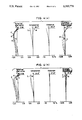
- FIGS. 1, 3 and 5 are sectional views of the 1st, 2nd and 3rd embodiments of the zoom lens system according to this invention, respectively, and
- FIGS. 2, 4 and 6 are aberrational diagrams of the 1st-3rd embodiments at the wide angle, standard and telephoto settings (a), (b) and (c), respectively.
- F NO . presents the F number, ⁇ the half field angle, r 1 , r 2 and so on the radii of curvature of the respective lens surfaces d 1 , d 2 and so on the spaces between the respective lens surfaces n d1 , n d2 and so on the refractive indices at the d lines of the respective lenses and ⁇ d1 , ⁇ d2 and so on the Abbe's numbers of the respective lenses.
- An aspherical geometry with the apex defined as the origin is expressed by the following equation:
- x is the optical axis direction
- y is the direction at right angles with the optical axis
- r is the paraxal radius of curvature
- E, F and G are the aspherical coefficients.
- FIG. 1 is a sectional view at the wide angle end of the zoom lens system according to Example 1, which is built up of a first lens group consisting of two negative meniscus lenses, each having its convex surface directed to the object side and one positive meniscus lens having its convex surface directed to the object side; a second lens group consisting of an aperture stop integrally provided in the front thereof, a positive meniscus lens having its convex surface directed to the object side, a double-convex positive lens, a double-concave negative lens and two double-convex positive lenses; and a third lens group consisting of a positive meniscus lens having its convex surface directed to the image plane side, a double-concave negative lens and a positive meniscus lens having its convex surface directed to the image plane side.
- the aberrational diagrams of this lens system at the wide angle, standard and telephoto settings are shown in FIGS. 2a, 2b and 2c.
- FIG. 3 is a sectional view at the wide angle end of the zoom lens system according to Example 2, which is built up of a first lens group consisting of a negative meniscus lens having its convex surface directed to the object side, a negative meniscus lens having its concave surface directed to the object side and a double-convex positive lens; a second lens group consisting of two positive meniscus lenses, each having its convex surface directed to the object side, a double-concave negative lens, two double-convex lenses and an aperture spot integrally provided in the rear thereof; and a third lens group consisting of a positive meniscus lens having its convex surface directed to the image plane side and two positive meniscus lenses, each having its convex surface directed to the image plane side.
- the aberrational diagrams of this lens system at the wide angle, standard and telephoto settings are shown in FIGS. 4a, 4b and 4c.
- FIG. 5 is a sectional view at the wide angle end of the zoom lens system according to Example 3, which is built up of a first lens group consisting of a negative meniscus lens having its convex surface directed to the object side, a double-concave negative lens and a positive meniscus lens having its convex surface directed to the object side; a second lens group consisting of an aperture stop integrally provided in the front thereof, a positive meniscus lens having its convex surface directed to the object side, a double-convex positive lens, a double-concave negative lens and two double-convex positive lenses; and a third lens group consisting of a positive meniscus lens having its convex surface directed to the image plane side and a double-concave negative lens.
- the aberrational diagrams of this lens system at the wide angle, standard and telephoto settings are shown in FIGS. 6a, 6b and 6c.
- the wide angle zoom lens systems according to this invention have a field angle of 70° or more at the wide angle end and a zoom ratio of 3 or more, are more reduced in the number of lenses involved and the overall length than this class of zoom lens system and have a back focal distance enough to reduce the diameter of the third lens groups; they are compact and have improved aberrational performance.
- the zoom lens systems according to this invention are best-suited for use with the lens shutter cameras in particular.
Abstract
The present invention provides a zoom lens system designed to be used with cameras which are limitless in terms of their back focal distances, like "lens shutter cameras" and, more particularly, a ternary negative-positive-negative type of wide angle zoom lens system which has an extended zoom range toward the wide angle side so that it can have a field angle of 70° or more at the wide angle end and a zoom ratio of 3 or more, is reduced in the number of lenses involved and the overall length and is made compact. This zoom lens system--which is built up of, in order from the object side, a first lens group of negative refracting power, a second lens group of positive refracting power and a third lens group of negative refracting power.
Description
(a) Field of the invention
The present invention relates to a wide angle zoom lens system lending itself well fit for use with cameras which are limitless in terms of their back focal distances, like "lens shutter cameras" and, more particularly, to a ternary negative-positive-negative type of wide angle zoom lens system which has an extended zoom range toward the wide angle side so that it can have a field angle of 70° or more at the wide angle end and a zoom ratio of 3 or more.
(b) Description of the Prior Art
So far, many types of zoom lens systems have been known for use with the lens shutter cameras which are limitless in terms of their back focal distances, or other cameras. Of these systems, however, the binary positive-negative type of zoom lens systems are found to have a zoom ratio of at most 2. There are also available ternary zoom lens systems having a zoom ratio of about 3, which are represented by such a ternary positive-positive-negative type of zoom lens system as set forth in Japanese Patent Laid-Open Publication No. 63 (1988)-153511, such a ternary negative-positive-negative type of zoom lens system as described in Japanese Patent Laid-Open Publication No. 64(1989)-72114 and such a ternary positive-negative-positive type of zoom lens system as disclosed in Japanese Patent Laid-Open Publication No. 2(1990)-71220. Japanese Patent Laid-Open Publication No. 2(1990)-37317, on the other hand, proposes a zoom lens system which exceeds 3 in terms of zoom ratio and has a zoom ratio extended toward the wide angle side by reducing its focal length on the wide angle side.
A problem with the binary type of zoom lens system, however, is that when it is intended to extend the zoom ratio to about 3, there is an increase in variations of the magnification of the second lens group; much difficulty is encountered in correcting aberrations because of aberrational fluctuations increased by zooming.
With the ternary type of zoom lens systems, it may be possible to extend the zoom ratio to about 3. However, when the first lens group is of positive refracting power, as is the case with the positive-positive-negative or positive-negative-positive system, it is difficult to form a retrofocus design at the wide angle side. When it is intended to extend the zoom ratio toward the wide angle side, therefore, it is impossible to have sufficient back focal distance, thus causing the off-axial bundle of rays to pass through the 3rd lens group at a position far off the optical axis. This results in an increase in the diameter of the 3rd lens group and renders it difficult to correct off-axial aberrations. In addition, because the associated film surface is located too closely to the surface of the last lens, it is likely that dust deposits on the surface of the last lens may be transferred onto the film, or ghost rays may be emitted by the reflection of light off the film and the surface of the last lens.
By contrast, the ternary negative-positive-negative type of zoom lens system can have sufficient back focal distance at the wide angle side, because it is easy to obtain a retrofocus design at the wide angle side. However, a problem with this type is that difficulty is involved in obtaining a telephoto design at the telephoto side, thus giving rise to an increase in the overall length on the telephoto side. The zoom lens system referred to in the above-mentioned Japanese Patent Laid-Open Publication 2-37317--wherein the zoom ratio is extended by reducing the focal length at the wide angle side to 28.8 mm--also presents a problem that it is increased in the number of lenses involved, with the resulting increase in the overall length at the telephoto side.
In view of the foregoing, an object of this invention is to solve the above-mentioned problems associated with the prior art by the provision of a ternary negative-positive-negative type of wide angle zoom lens system, which has an extended zoom range toward the wide angle side so that it can have a field angle of 70° or more at the wide angle end and a zoom ratio of 3 or more, is more reduced in the number of lenses involved and the overall length and more compact than this class of conventional zoom lens systems, and is much more improved in terms of aberrational performance.
According to this invention, the above-mentioned object is well accomplished by providing a wide angle zoom lens system which is built up of, in order from the object side, a first lens group of negative refracting power, a second lens group of positive refracting power and a third lens group of negative refracting power, as can be best seen from FIGS. 1, 3 and 5, and in which both the air spaces between the 1st and 2nd lens groups and the 2nd and 3rd lens groups are narrowed when the power is varied from the wide angle side to the telephoto side, characterized by satisfying the following conditions:
0.1<f.sub.12T /F.sub.T <0.35 (1)
1.0<|β.sub.3W ·f.sub.3 /F.sub.W |<2.0(2)
2.2<β.sub.3T /β.sub.3W <3.5 (3)
wherein:
FW is the focal length of the overall system at the wide angle end,
FT is the focal length of the overall system at the telephoto end,
f12T is the combined focal length of the 1st and 2nd lens groups at the telephoto end,
f3 is the focal length of the 3rd lens group,
β3W is the lateral magnification of the 3rd lens group at the wide angle end, and
β3T is the lateral magnification of the 3rd lens group at the telephoto end.
Preferably, an aperture stop is located before or after the 2nd lens groups such that it moves together with the 2nd lens group during zooming.
In the description that follows, the action of this invention will be explained specifically with reference to the above-defined conditions, etc.
Condition (1) concerns the overall length of the lens system at the telephoto end. Now considering a telephoto type of lens system built up of a front positive lens group defined by the 1st and 2nd lens groups and a rear negative lens group defined by the 3rd lens group, it is then noted that the shorter the combined focal length f12T of the 1st and 2nd lens groups with respect to the focal length FT of the overall system, the more enhanced the telephoto effect or, in other words, the more advantageously is the reduction in the overall length achieved. Too enhanced a telephoto effect, however, causes that the focal length f3 of the 3rd lens group is so shortened that difficulty will be involved in correcting aberrations, esp., correcting off-axial aberrations at the wide angle side. This is the reason that Condition (1) is provided as one requirement of this invention. At higher than the upper limit of 0.35 the overall length on the telephoto side will be too long to make the system compact, whereas at less than the lower limit of 0.1 difficulty will be encountered in correcting off-axial aberrations on the wide angle side in particular and in improving aberrational performance.
Condition (2) is directed to the back focal distance of the lens system at the wide angle end. At higher than the upper limit of 2.0, it has a back focal distance that is longer than required and so is unpreferred for use with, e.g. a lens shutter camera; it becomes too long in the overall length at the wide angle end. At less than the lower limit of 1.0, it has a back focal distance so short that, as already mentioned in connection with the problems of the prior art, the 3rd lens group is increased in diameter and difficulty will be experienced in correcting off-axial aberrations. In addition, as the associated film surface is located too closely to the surface of the last lens, it is likely that dust deposits on the surface of the last lens may be transferred onto the film, or ghost rays may be emitted by the reflection of light off the film and the surface of the last lens.
Condition (3) is provided for determining the rate of variable power of the 3rd lens group so as to obtain the required zoom ratio. At higher than the upper limit of 3.5, the magnification shared by the 3rd lens group during zooming is so high that the amount of movement of the 3rd lens group by zooming is increased, rendering it difficult to design the associated lens barrel and incurring an increase in aberrational variations by zooming. At below the lower limit of 2.2, on the other hand, it is impossible to obtain the required zoom ratio without increasing the rate of variable power shared by the 2nd lens group. To this end, it is necessary to enlarge the space between the 1st and 2nd lens groups at the wide angle end and increase the amount of movement of the 2nd lens group. However, this renders it difficult to reduce the overall length of the lens system.
In the present zoom lens system, the aperture stop--which is designed to move together with the 2nd lens group during zooming--is located before or after the 2nd lens group. This aperture stop may possibly be located within the 2nd lens group. With such an arrangement, however, it is required to divide the lens barrel into two parts before and after the aperture stop, thus making the 2nd lens group likely to become off-center before and after the aperture stop. In addition, this increases the number of parts of the lens barrel and so renders it costly.
In order to obtain much more improved lens performance, the lenses of each group should be constructed as follows.
The 1st lens group includes at least one positive lens with the nearest lens to the object side being made up of a negative meniscus lens having its convex surface directed to the object side.
The 2nd lens group includes at least one double-concave negative lens with positive lenses located on the object and image sides, respectively.
The 3rd lens group includes a positive meniscus lens having its convex surface directed to the image plane side as the nearest lens to the object side, and contains at least one negative lens.
More preferably, at least one lens of the 2nd lens group is made up of an aspheric lens with a view to facilitating correction of spherical and coma aberrations.
If some aspheric lens surfaces are used for the 1st and 3rd lens groups, then it is possible to achieve further reductions in the overall length and the number of lenses involved.
Still other objects and advantages of the invention will in part be obvious and will in part be apparent from the specification.
The invention accordingly comprises the features of construction, combinations of elements, and arrangement of parts which will be exemplified in the construction hereinafter set forth, and the scope of the invention will be indicated in the claims.
FIGS. 1, 3 and 5 are sectional views of the 1st, 2nd and 3rd embodiments of the zoom lens system according to this invention, respectively, and
FIGS. 2, 4 and 6 are aberrational diagrams of the 1st-3rd embodiments at the wide angle, standard and telephoto settings (a), (b) and (c), respectively.
In what follows, the present invention will be explained more illustratively but not exclusively with reference to the preferred embodiments. Throughout the present disclosure, symbols other than the above-mentioned ones have the following meanings: FNO. presents the F number, ω the half field angle, r1, r2 and so on the radii of curvature of the respective lens surfaces d1, d2 and so on the spaces between the respective lens surfaces nd1, nd2 and so on the refractive indices at the d lines of the respective lenses and νd1, νd2 and so on the Abbe's numbers of the respective lenses. An aspherical geometry with the apex defined as the origin is expressed by the following equation:
x=y.sup.2 /{r+(r.sup.2 -y.sup.2).sup.1/2 }+Ey.sup.4 +Fy.sup.6 +Gy.sup.8
wherein:
x is the optical axis direction,
y is the direction at right angles with the optical axis,
r is the paraxal radius of curvature, and
E, F and G are the aspherical coefficients.
______________________________________
         f = 28.85˜54.43˜102.83
         F.sub.NO = 2.88˜4.85˜8.14
         2 ω = 72.2°˜42.2°˜23.4°
         f.sub.B = 6.51˜32.59˜74.07
r.sub.1 = 33.333
          d.sub.1 = 1.80
                      n.sub.d1 = 1.77250
                                  ν.sub.d1 = 49.66
r.sub.2 = 19.124
          d.sub.2 = 10.42
r.sub.3 = 180.540
          d.sub.3 = 1.40
                      n.sub.d2 = 1.72916
                                  ν.sub.d2 = 54.68
r.sub.4 = 95.800
          d.sub.4 = 0.43
r.sub.5 = 25.676
          d.sub.5 = 2.75
                      n.sub.d3 = 1.80518
                                  ν.sub.d3 = 25.43
r.sub.6 = 33.182
          d.sub.6 = (Varia-
          ble)
r.sub.7 = ∞ (Stop)
          d.sub.7 = 0.50
r.sub.8 = 31.551
          d.sub.8 = 2.82
                      n.sub.d4 = 1.56883
                                  ν.sub.d4 = 56.34
(Aspheric)
r.sub.9 = d.sub.9 = 0.08
r.sub.10 = 22.557
          d.sub.10 = 2.93
                      n.sub.d5 = 1.51633
                                  ν.sub.d5 = 64.15
r.sub.11 = -231.235
          d.sub.11 = 3.87
r.sub.12 = -56.714
          d.sub.12 = 1.21
                      n.sub.d6 = 1.80518
                                  ν.sub.d6 = 25.43
r.sub.13 = 26.984
          d.sub.13 = 1.00
r.sub.14 = 104.466
          d.sub.14 = 3.18
                      n.sub.d7 = 1.59551
                                  ν.sub.d7 = 39.21
r.sub.15 = -27.270
          d.sub.15 = 0.20
r.sub.16 = 48.981
          d.sub.16 = 2.27
                      n.sub.d8 = 1.54739
                                  ν.sub.d8 = 53.55
r.sub.17 = -41.957
          d.sub.17 = (Varia-
          ble)
r.sub.18 = -38.056
          d.sub.18 = 3.02
                      n.sub.d9 = 1.69895
                                  ν.sub.d9 = 30.12
r.sub.19 = -21.111
          d.sub.19 = 3.72
r.sub.20 = -18.485
          d.sub.20 = 1.50
                      n.sub.d10 = 1.77250
                                  ν.sub.d10 = 49.66
r.sub.21 = 56.024
          d.sub.21 = 3.17
r.sub.22 = -115.228
          d.sub.22 = 1.70
                      n.sub.d11 = 1.69895
                                  ν.sub.d11 = 30.12
r.sub.23 = -67.121
Zooming spaces
f       28.85         54.43  102.83
d.sub.6 31.27         16.02  2.00
d.sub.17
        12.18          4.80  1.00
         Aspherical Coefficients
         8th surface
         E = -1.0908 × 10.sup.-5
         F = -2.3676 × 10.sup.-8
         G = -2.3232 × 10.sup.-10
         f.sub.12T /F.sub.T = 0.28
         |β.sub.3W · f.sub.3 /F.sub.W | =
         1.44
         β.sub.3T /β.sub.3W = 2.63
______________________________________
______________________________________
         f = 28.81˜54.39˜102.93
         F.sub.NO = 2.88˜5.08˜8.25
         2 ω = 76.6°˜43.6°˜23.6°
         f.sub.B = 6.50˜32.15˜64.84
r.sub.1 = 55.502
          d.sub.1 = 1.80
                      n.sub.d1 = 1.77250
                                  ν.sub.d1 = 49.66
r.sub.2 = 35.208
          d.sub.2 = 12.66
r.sub.3 = -58.027
          d.sub.3 = 1.40
                      n.sub.d2 = 1.72916
                                  ν.sub.d2 = 54.68
r.sub.4 = -1402.140
          d.sub.4 = 0.43
r.sub.5 = 144.150
          d.sub.5 = 3.31
                      n.sub.d3 = 1.78472
                                  ν.sub.d3 = 25.68
r.sub.6 = -342.728
          d.sub.6 = (Varia-
          ble)
r.sub.7 = 32.964
          d.sub.7 = 2.23
                      n.sub.d4 = 1.49831
                                  ν.sub.d4 = 65.03
r.sub.8 = 96.707
          d.sub.8 = 0.09
r.sub.9 = 20.343
          d.sub. 9 = 3.33
                      n.sub.d5 = 1.50137
                                  ν.sub.d5 = 56.40
r.sub.10 = 130.602
          d.sub.10 = 3.25
r.sub.11 = -25.793
          d.sub.11 = 1.20
                      n.sub.d6 = 1.80518
                                  ν.sub.d6 = 25.43
r.sub.12 = 372.173
          d.sub.12 = 1.00
r.sub.13 = 410.989
          d.sub.13 = 4.00
                      n.sub.d7 = 1.50137
                                  ν.sub.d7 = 56.40
r.sub.14 = -24.801
          d.sub.14 = 0.20
r.sub.15 = 78.978
          d.sub.15 = 3.80
                      n.sub.d8 = 1.53172
                                  ν.sub.d8 = 48.90
r.sub.16 = -36.188
          d.sub.16 = 0.50
(Aspheric)
r.sub.17 = ∞ (Stop)
          d.sub.17 = (Varia-
          ble)
r.sub.18 = -26.112
          d.sub.18 = 3.02
                      n.sub.d9 = 1.69895
                                  ν.sub.d9 = 30.12
r.sub.19 = -16.544
          d.sub.19 = 2.30
r.sub.20 = -18.568
          d.sub.20 = 1.50
                      n.sub.d10 = 1.77250
                                  ν.sub.d10 = 49.66
r.sub.21 = -32.310
          d.sub.21 = 3.63
r.sub.22 = -14.514
          d.sub.22 = 1.70
                      n.sub.d11 = 1.77250
                                  ν.sub.d11 = 49.66
r.sub.23 = -48.465
Zooming spaces
f       28.81         54.39  102.93
d.sub.6 28.50         19.45  1.50
d.sub.17
        12.77          4.95  2.70
         Aspherical Coefficients
         8th surface
         E = -1.9720 × 10.sup.-5
         F = -1.2270 × 10.sup.-8
         G = -1.3245 × 10.sup.-9
         f.sub.12T /F.sub.T = 0.29
         |β.sub.3W · f.sub.3 /F.sub.W | =
         1.23
         β.sub.3T /β.sub.3W = 2.65
______________________________________
______________________________________
         f = 28.8˜54.4˜102.87
         F.sub.NO = 2.88˜5.04˜8.17
         2 ω = 74.8°˜42.6°˜23.4°
         f.sub.B = 6.74˜35.37˜72.79
r.sub.1 = 27.900
          d.sub.1 = 1.80
                      n.sub.d1 = 1.77250
                                  ν.sub.d1 = 49.66
r.sub.2 = 19.349
          d.sub.2 = 12.16
r.sub.3 = -848.900
          d.sub.3 = 1.40
                      n.sub.d2 = 1.72916
                                  ν.sub.d2 = 54.68
r.sub.4 = 87.206
          d.sub.4 = 0.43
r.sub.5 = 32.332
          d.sub.5 = 2.93
                      n.sub.d3 = 1.80518
                                  ν.sub.d3 = 25.43
r.sub.6 = 49.300
          d.sub.6 = (Varia-
          ble)
r.sub.7 = ∞ (Stop)
          d.sub.7 = 0.50
r.sub.8 = 27.313
          d.sub.8 = 3.08
                      n.sub.d4 = 1.51633
                                  ν.sub.d4 = 64.15
(Aspheric)
r.sub.9 = d.sub.9 = 0.08
r.sub.10 = 21.007
          d.sub.10 = 3.09
                      n.sub.d5 = 1.51633
                                  ν.sub.d5 = 64.15
r.sub.11 = -125.314
          d.sub.11 = 3.91
r.sub.12 = -57.057
          d.sub.12 = 1.21
                      n.sub.d6 = 1.80518
                                  ν.sub.d6 = 25.43
r.sub.13 = 22.425
          d.sub.13 = 1.00
r.sub.14 = 204.738
          d.sub.14 = 3.26
                      n.sub.d7 = 1.58267
                                  ν.sub.d7 = 46.33
r.sub.15 = -26.902
          d.sub.15 = 0.20
r.sub.16 = 64.053
          d.sub.16 = 2.60
                      n.sub.d8 = 1.59551
                                  ν.sub.d8 = 39.21
r.sub.17 = -47.918
          d.sub.17 = (Varia-
          ble)
r.sub.18 = -28.996
          d.sub.18 = 3.21
                      n.sub.d9 = 1.80518
                                  ν.sub.d9 = 25.43
r.sub.19 = -18.484
          d.sub.19 =  3.42
r.sub.20 = -16.805
          d.sub.20 = 1.50
                      n.sub.d10 = 1.77250
                                  ν.sub.d10 = 49.66
(Aspheric)
r.sub.21 = 270.807
Zooming spaces
f       28.8          54.4   102.87
d.sub.6 28.99         19.40  2.10
d.sub.17
        15.14          4.64  1.00
         Aspherical Coefficients
         8th surface
         E = -9.3900 × 10.sup.-6
         F = -5.3817 × 10.sup.-8
         G = -1.7664 × 10.sup.-11
         20th surface
         E = -2.0790 × 10.sup.-6
         F = 3.4889 × 10.sup.-8
         G = 1.7625 × 10.sup.-12
         f.sub.12T /F.sub.T = 0.31
         |β.sub.3W · f.sub.3 /F.sub.W | =
         1.39
         β.sub.3T /β.sub.3W = 2.65
______________________________________
As already mentioned, FIG. 1 is a sectional view at the wide angle end of the zoom lens system according to Example 1, which is built up of a first lens group consisting of two negative meniscus lenses, each having its convex surface directed to the object side and one positive meniscus lens having its convex surface directed to the object side; a second lens group consisting of an aperture stop integrally provided in the front thereof, a positive meniscus lens having its convex surface directed to the object side, a double-convex positive lens, a double-concave negative lens and two double-convex positive lenses; and a third lens group consisting of a positive meniscus lens having its convex surface directed to the image plane side, a double-concave negative lens and a positive meniscus lens having its convex surface directed to the image plane side. The aberrational diagrams of this lens system at the wide angle, standard and telephoto settings are shown in FIGS. 2a, 2b and 2c.
FIG. 3 is a sectional view at the wide angle end of the zoom lens system according to Example 2, which is built up of a first lens group consisting of a negative meniscus lens having its convex surface directed to the object side, a negative meniscus lens having its concave surface directed to the object side and a double-convex positive lens; a second lens group consisting of two positive meniscus lenses, each having its convex surface directed to the object side, a double-concave negative lens, two double-convex lenses and an aperture spot integrally provided in the rear thereof; and a third lens group consisting of a positive meniscus lens having its convex surface directed to the image plane side and two positive meniscus lenses, each having its convex surface directed to the image plane side. The aberrational diagrams of this lens system at the wide angle, standard and telephoto settings are shown in FIGS. 4a, 4b and 4c.
FIG. 5 is a sectional view at the wide angle end of the zoom lens system according to Example 3, which is built up of a first lens group consisting of a negative meniscus lens having its convex surface directed to the object side, a double-concave negative lens and a positive meniscus lens having its convex surface directed to the object side; a second lens group consisting of an aperture stop integrally provided in the front thereof, a positive meniscus lens having its convex surface directed to the object side, a double-convex positive lens, a double-concave negative lens and two double-convex positive lenses; and a third lens group consisting of a positive meniscus lens having its convex surface directed to the image plane side and a double-concave negative lens. The aberrational diagrams of this lens system at the wide angle, standard and telephoto settings are shown in FIGS. 6a, 6b and 6c.
As explained with reference to the above-mentioned examples, the wide angle zoom lens systems according to this invention have a field angle of 70° or more at the wide angle end and a zoom ratio of 3 or more, are more reduced in the number of lenses involved and the overall length than this class of zoom lens system and have a back focal distance enough to reduce the diameter of the third lens groups; they are compact and have improved aberrational performance. The zoom lens systems according to this invention are best-suited for use with the lens shutter cameras in particular.
Claims (5)
1. A wide angle zoom lens system which is built up of, in order from the object side, a first lens group of negative refracting power, a second lens group of positive refracting power and a third lens group of negative refracting power and in which both the air spaces between the 1st and 2nd lens groups and the 2nd and 3rd lens groups are narrowed when the power is varied from the wide angle side to the telephoto side, characterized by satisfying the following conditions:
0.1<f.sub.12T /F.sub.T <0.35 (1)
1.0<|β.sub.3W ·f.sub.3 /F.sub.W |<2.0(2)
2.2<β.sub.3T /β.sub.3W <3.5 (3)
wherein:
FW is the focal length of the overall system at the wide angle end,
FT is the focal length of the overall system at the telephoto end,
f12T is the combined focal length of the 1st and 2nd lens groups at the telephoto end,
f3 is the focal length of the 3rd lens group,
β3W is the lateral magnification of the 3rd lens group at the wide angle end, and
β3T is the lateral magnification of the 3rd lens group at the telephoto end.
2. A wide angle zoom lens system as claimed in claim 1, characterized in that an aperture stop is located before or after said second lens group such that it moves together with said second lens group during zooming.
3. A wide angle zoom lens system as claimed in claim 1 or 2, characterized in that said 1st lens group includes at least one positive lens with the nearest lens to the object side made up of a negative meniscus lens having its convex surface directed to the object side, said 2nd lens group includes at least one double-concave negative lens with positive lenses located on the object and image plane sides, respectively, and said 3rd lens group includes a positive meniscus lens having its convex surface directed to the image plane side as the nearest lens to the object side and contains at least one negative lens.
4. A wide angle zoom lens system as claimed in any one of claims 1-2, characterized in that at least one lens of said 2nd lens group is made up of an aspherical lens.
5. A wide angle zoom lens system as claimed in claim 4, characterized in that at least one lens surface of said 1st or 3rd lens group is made up of an aspherical lens.
Applications Claiming Priority (2)
| Application Number | Priority Date | Filing Date | Title |
|---|---|---|---|
| JP2210744A JPH0497112A (en) | 1990-08-09 | 1990-08-09 | Wide-angle zoom lens |
| JP2-210744 | 1990-08-09 |
Publications (1)
| Publication Number | Publication Date |
|---|---|
| US5153776A true US5153776A (en) | 1992-10-06 |
Family
ID=16594402
Family Applications (1)
| Application Number | Title | Priority Date | Filing Date |
|---|---|---|---|
| US07/741,044 Expired - Lifetime US5153776A (en) | 1990-08-09 | 1991-08-06 | Wide angle zoom lens system |
Country Status (2)
| Country | Link |
|---|---|
| US (1) | US5153776A (en) |
| JP (1) | JPH0497112A (en) |
Cited By (10)
| Publication number | Priority date | Publication date | Assignee | Title |
|---|---|---|---|---|
| US5461512A (en) * | 1993-11-30 | 1995-10-24 | Eastman Kodak Company | Zoom camera lens having three moving groups |
| US5966247A (en) * | 1997-12-19 | 1999-10-12 | Eastman Kodak Company | Compact zoom lens |
| US20040136087A1 (en) * | 2002-10-23 | 2004-07-15 | Makoto Hirakawa | Zoom lens, camera, and portable information terminal apparatus |
| US20090170691A1 (en) * | 2007-12-28 | 2009-07-02 | Chevron Phillips Chemical Company | Nano-linked metallocene catalyst compositions and their polymer products |
| US20090170690A1 (en) * | 2007-12-28 | 2009-07-02 | Chevron Phillips Chemical Company | Nano-linked metallocene catalyst compositions and their polymer products |
| US20090171041A1 (en) * | 2007-12-28 | 2009-07-02 | Chevron Phillips Chemical Company | Nano-linked metallocene catalyst compositions and their polymer products |
| US20100324236A1 (en) * | 2009-06-23 | 2010-12-23 | Chevron Phillips Chemical Company Lp | Nano-linked heteronuclear metallocene catalyst compositions and their polymer products |
| CN103744171A (en) * | 2009-04-13 | 2014-04-23 | 株式会社腾龙 | Wide-angle zoom lens |
| US10185131B2 (en) | 2013-07-30 | 2019-01-22 | Olympus Corporation | Zoom lens and lens barrel and image pickup apparatus using the same |
| CN110161666A (en) * | 2019-05-20 | 2019-08-23 | 安徽长庚光学科技有限公司 | A kind of high magnification micro-lens |
Families Citing this family (7)
| Publication number | Priority date | Publication date | Assignee | Title |
|---|---|---|---|---|
| JP2974522B2 (en) * | 1992-11-19 | 1999-11-10 | キヤノン株式会社 | Small zoom lens |
| KR0172009B1 (en) * | 1994-09-26 | 1999-05-01 | 이대원 | Wide angle zoom lens |
| KR100440101B1 (en) * | 2001-08-31 | 2004-07-14 | 삼성테크윈 주식회사 | Wide-angle zoom lens |
| JP4624744B2 (en) * | 2004-08-31 | 2011-02-02 | オリンパス株式会社 | Wide angle zoom lens |
| JP4681842B2 (en) * | 2004-09-30 | 2011-05-11 | キヤノン株式会社 | Zoom lens and imaging apparatus having the same |
| JP5601572B2 (en) * | 2010-06-24 | 2014-10-08 | 株式会社リコー | Imaging lens, imaging device, and information device |
| KR20200085205A (en) * | 2019-01-04 | 2020-07-14 | 엘지이노텍 주식회사 | Optical system and camera module for comprising the same |
Citations (5)
| Publication number | Priority date | Publication date | Assignee | Title |
|---|---|---|---|---|
| JPH0237317A (en) * | 1988-07-28 | 1990-02-07 | Konica Corp | Compact zoom lens |
| US4934794A (en) * | 1987-12-19 | 1990-06-19 | Minolta Camera Kabushiki Kaisha | Zoom lens system for use in microfilm projection apparatus |
| US4936661A (en) * | 1987-07-23 | 1990-06-26 | Opcon Associates, Inc. | Zoom lens with short back focal length |
| US4955700A (en) * | 1988-08-30 | 1990-09-11 | Ricoh Company, Ltd. | Small-size zoom lens system |
| US5042926A (en) * | 1989-01-23 | 1991-08-27 | Ricoh Company, Ltd. | Zoom lens and focusing method |
-
1990
- 1990-08-09 JP JP2210744A patent/JPH0497112A/en active Pending
-
1991
- 1991-08-06 US US07/741,044 patent/US5153776A/en not_active Expired - Lifetime
Patent Citations (5)
| Publication number | Priority date | Publication date | Assignee | Title |
|---|---|---|---|---|
| US4936661A (en) * | 1987-07-23 | 1990-06-26 | Opcon Associates, Inc. | Zoom lens with short back focal length |
| US4934794A (en) * | 1987-12-19 | 1990-06-19 | Minolta Camera Kabushiki Kaisha | Zoom lens system for use in microfilm projection apparatus |
| JPH0237317A (en) * | 1988-07-28 | 1990-02-07 | Konica Corp | Compact zoom lens |
| US4955700A (en) * | 1988-08-30 | 1990-09-11 | Ricoh Company, Ltd. | Small-size zoom lens system |
| US5042926A (en) * | 1989-01-23 | 1991-08-27 | Ricoh Company, Ltd. | Zoom lens and focusing method |
Cited By (26)
| Publication number | Priority date | Publication date | Assignee | Title |
|---|---|---|---|---|
| US5461512A (en) * | 1993-11-30 | 1995-10-24 | Eastman Kodak Company | Zoom camera lens having three moving groups |
| US5966247A (en) * | 1997-12-19 | 1999-10-12 | Eastman Kodak Company | Compact zoom lens |
| US20040136087A1 (en) * | 2002-10-23 | 2004-07-15 | Makoto Hirakawa | Zoom lens, camera, and portable information terminal apparatus |
| US6804064B2 (en) * | 2002-10-23 | 2004-10-12 | Ricoh Company, Ltd. | Zoom lens, camera, and portable information terminal apparatus |
| US20050030640A1 (en) * | 2002-10-23 | 2005-02-10 | Makoto Hirakawa | Zoom lens, camera, and portable information terminal apparatus |
| US7079326B2 (en) | 2002-10-23 | 2006-07-18 | Ricoh Company, Ltd. | Zoom lens, camera, and portable information terminal apparatus |
| US8329833B2 (en) | 2007-12-28 | 2012-12-11 | Chevron Phillips Chemical Company Lp | Nano-linked metallocene catalyst compositions and their polymer products |
| US8080681B2 (en) | 2007-12-28 | 2011-12-20 | Chevron Phillips Chemical Company Lp | Nano-linked metallocene catalyst compositions and their polymer products |
| US20090171041A1 (en) * | 2007-12-28 | 2009-07-02 | Chevron Phillips Chemical Company | Nano-linked metallocene catalyst compositions and their polymer products |
| US8524626B2 (en) | 2007-12-28 | 2013-09-03 | Chevron Phillips Chemical Company Lp | Nano-linked metallocene catalyst compositions and their polymer products |
| US7863210B2 (en) * | 2007-12-28 | 2011-01-04 | Chevron Phillips Chemical Company Lp | Nano-linked metallocene catalyst compositions and their polymer products |
| US20110059840A1 (en) * | 2007-12-28 | 2011-03-10 | Chevron Phillips Chemical Company Lp | Nano-linked metallocene catalyst compositions and their polymer products |
| US20090170691A1 (en) * | 2007-12-28 | 2009-07-02 | Chevron Phillips Chemical Company | Nano-linked metallocene catalyst compositions and their polymer products |
| US8143183B2 (en) | 2007-12-28 | 2012-03-27 | Chevron Phillips Chemical Company Lp | Nano-linked metallocene catalyst compositions and their polymer products |
| US8012900B2 (en) | 2007-12-28 | 2011-09-06 | Chevron Phillips Chemical Company, L.P. | Nano-linked metallocene catalyst compositions and their polymer products |
| US20090170690A1 (en) * | 2007-12-28 | 2009-07-02 | Chevron Phillips Chemical Company | Nano-linked metallocene catalyst compositions and their polymer products |
| CN103744171A (en) * | 2009-04-13 | 2014-04-23 | 株式会社腾龙 | Wide-angle zoom lens |
| CN103744171B (en) * | 2009-04-13 | 2016-08-17 | 株式会社腾龙 | wide-angle zoom lens |
| US8143430B2 (en) | 2009-06-23 | 2012-03-27 | Chevron Phillips Chemical Company Lp | Nano-linked heteronuclear metallocene catalyst compositions and their polymer products |
| US20110144290A1 (en) * | 2009-06-23 | 2011-06-16 | Chevron Phillips Chemical Company Lp | Nano-linked heteronuclear metallocene catalyst compositions and their polymer products |
| US7919639B2 (en) | 2009-06-23 | 2011-04-05 | Chevron Phillips Chemical Company Lp | Nano-linked heteronuclear metallocene catalyst compositions and their polymer products |
| US8426536B2 (en) | 2009-06-23 | 2013-04-23 | Chevron Phillips Chemical Company Lp | Nano-linked heteronuclear metallocene catalyst compositions and their polymer products |
| US20100324236A1 (en) * | 2009-06-23 | 2010-12-23 | Chevron Phillips Chemical Company Lp | Nano-linked heteronuclear metallocene catalyst compositions and their polymer products |
| US10185131B2 (en) | 2013-07-30 | 2019-01-22 | Olympus Corporation | Zoom lens and lens barrel and image pickup apparatus using the same |
| CN110161666A (en) * | 2019-05-20 | 2019-08-23 | 安徽长庚光学科技有限公司 | A kind of high magnification micro-lens |
| CN110161666B (en) * | 2019-05-20 | 2024-03-26 | 安徽长庚光学科技有限公司 | High-magnification macro lens |
Also Published As
| Publication number | Publication date |
|---|---|
| JPH0497112A (en) | 1992-03-30 |
Similar Documents
| Publication | Publication Date | Title |
|---|---|---|
| US6016228A (en) | Zoom lens system | |
| US5153776A (en) | Wide angle zoom lens system | |
| US4772106A (en) | Compact zoom lens system | |
| US4606607A (en) | Photographic lens system with a short overall length | |
| JPH06337354A (en) | Zoom lens | |
| US5325235A (en) | Compact zoom lens system | |
| JP3365835B2 (en) | Compact 3-group zoom lens | |
| JP3352227B2 (en) | Zoom lens | |
| JP3162114B2 (en) | Two-group zoom lens | |
| US4235521A (en) | Photographic lens system | |
| JP3018723B2 (en) | Zoom lens | |
| US5260834A (en) | Small zoom lens system | |
| US5166828A (en) | Zoom lens system | |
| JP3302063B2 (en) | Rear focus compact zoom lens | |
| JP2808905B2 (en) | Zoom lens | |
| US5548447A (en) | Photographic lens system | |
| JP3486457B2 (en) | High magnification zoom lens including wide angle range | |
| US5768029A (en) | Zoom lens system | |
| JP3063248B2 (en) | Wide-angle zoom lens | |
| JPH0830783B2 (en) | High magnification zoom lens for compact cameras | |
| JP3268824B2 (en) | Small two-group zoom lens | |
| JPH09211327A (en) | Zoom lens | |
| US4708443A (en) | Zoom lens system | |
| US4443069A (en) | Compact camera lens system with a short overall length | |
| JP3414499B2 (en) | Zoom lens |
Legal Events
| Date | Code | Title | Description |
|---|---|---|---|
| AS | Assignment |
Owner name: OLYMPUS OPTICAL CO., LTD. Free format text: ASSIGNMENT OF ASSIGNORS INTEREST.;ASSIGNOR:NOZAWA, TOSHIHIDE;REEL/FRAME:005806/0761 Effective date: 19910701 |
|
| STCF | Information on status: patent grant |
Free format text: PATENTED CASE |
|
| FEPP | Fee payment procedure |
Free format text: PAYOR NUMBER ASSIGNED (ORIGINAL EVENT CODE: ASPN); ENTITY STATUS OF PATENT OWNER: LARGE ENTITY |
|
| FPAY | Fee payment |
Year of fee payment: 4 |
|
| FPAY | Fee payment |
Year of fee payment: 8 |
|
| FPAY | Fee payment |
Year of fee payment: 12 |