US5154347A - Ultrasonically generated cavitating or interrupted jet - Google Patents
Ultrasonically generated cavitating or interrupted jet Download PDFInfo
- Publication number
- US5154347A US5154347A US07/672,217 US67221791A US5154347A US 5154347 A US5154347 A US 5154347A US 67221791 A US67221791 A US 67221791A US 5154347 A US5154347 A US 5154347A
- Authority
- US
- United States
- Prior art keywords
- nozzle
- orifice
- transformer
- transformer means
- fluid
- Prior art date
- Legal status (The legal status is an assumption and is not a legal conclusion. Google has not performed a legal analysis and makes no representation as to the accuracy of the status listed.)
- Expired - Fee Related
Links
Images


Classifications
-
- B—PERFORMING OPERATIONS; TRANSPORTING
- B24—GRINDING; POLISHING
- B24C—ABRASIVE OR RELATED BLASTING WITH PARTICULATE MATERIAL
- B24C5/00—Devices or accessories for generating abrasive blasts
- B24C5/005—Vibratory devices, e.g. for generating abrasive blasts by ultrasonic vibrations
-
- B—PERFORMING OPERATIONS; TRANSPORTING
- B05—SPRAYING OR ATOMISING IN GENERAL; APPLYING FLUENT MATERIALS TO SURFACES, IN GENERAL
- B05B—SPRAYING APPARATUS; ATOMISING APPARATUS; NOZZLES
- B05B1/00—Nozzles, spray heads or other outlets, with or without auxiliary devices such as valves, heating means
- B05B1/02—Nozzles, spray heads or other outlets, with or without auxiliary devices such as valves, heating means designed to produce a jet, spray, or other discharge of particular shape or nature, e.g. in single drops, or having an outlet of particular shape
- B05B1/08—Nozzles, spray heads or other outlets, with or without auxiliary devices such as valves, heating means designed to produce a jet, spray, or other discharge of particular shape or nature, e.g. in single drops, or having an outlet of particular shape of pulsating nature, e.g. delivering liquid in successive separate quantities ; Fluidic oscillators
-
- B—PERFORMING OPERATIONS; TRANSPORTING
- B05—SPRAYING OR ATOMISING IN GENERAL; APPLYING FLUENT MATERIALS TO SURFACES, IN GENERAL
- B05B—SPRAYING APPARATUS; ATOMISING APPARATUS; NOZZLES
- B05B17/00—Apparatus for spraying or atomising liquids or other fluent materials, not covered by the preceding groups
- B05B17/04—Apparatus for spraying or atomising liquids or other fluent materials, not covered by the preceding groups operating with special methods
- B05B17/06—Apparatus for spraying or atomising liquids or other fluent materials, not covered by the preceding groups operating with special methods using ultrasonic or other kinds of vibrations
- B05B17/0607—Apparatus for spraying or atomising liquids or other fluent materials, not covered by the preceding groups operating with special methods using ultrasonic or other kinds of vibrations generated by electrical means, e.g. piezoelectric transducers
- B05B17/0623—Apparatus for spraying or atomising liquids or other fluent materials, not covered by the preceding groups operating with special methods using ultrasonic or other kinds of vibrations generated by electrical means, e.g. piezoelectric transducers coupled with a vibrating horn
-
- B—PERFORMING OPERATIONS; TRANSPORTING
- B24—GRINDING; POLISHING
- B24C—ABRASIVE OR RELATED BLASTING WITH PARTICULATE MATERIAL
- B24C1/00—Methods for use of abrasive blasting for producing particular effects; Use of auxiliary equipment in connection with such methods
-
- E—FIXED CONSTRUCTIONS
- E21—EARTH DRILLING; MINING
- E21B—EARTH DRILLING, e.g. DEEP DRILLING; OBTAINING OIL, GAS, WATER, SOLUBLE OR MELTABLE MATERIALS OR A SLURRY OF MINERALS FROM WELLS
- E21B7/00—Special methods or apparatus for drilling
- E21B7/18—Drilling by liquid or gas jets, with or without entrained pellets
-
- E—FIXED CONSTRUCTIONS
- E21—EARTH DRILLING; MINING
- E21B—EARTH DRILLING, e.g. DEEP DRILLING; OBTAINING OIL, GAS, WATER, SOLUBLE OR MELTABLE MATERIALS OR A SLURRY OF MINERALS FROM WELLS
- E21B7/00—Special methods or apparatus for drilling
- E21B7/24—Drilling using vibrating or oscillating means, e.g. out-of-balance masses
Definitions
- the present invention relates to a method and apparatus for enhancing the erosive capabilities of a high velocity liquid jet when directed against a surface to be eroded, and more particularly to an improved nozzle using ultrasonic energy to generate cavitation or pulsation in a high speed continuous water jet or to generate a plurality of converging discontinuous liquid jets.
- a percussive jet can be obtained by means of a rotor modulating a continuous stream of water at a predetermined frequency. More practically, the oscillations in the flow will be self-resonating and self-sustaining, created either by tandem orifices with a resonating chamber in between, or by means of standing waves in the pipe leading to the nozzle. It can be demonstrated that erosive intensity is considerably enhanced using percussive jets as compared to unmodulated continuous jets.
- cavitating jets that is, jets in which cavitation bubbles are induced either by means of a centre body in the nozzle, by turning vanes inducing vortex cavitation, or by directing the jet past sharp corners within the nozzle orifice causing pressure differentials across that orifice.
- cavitation means the rapid formation and collapse of vapour pockets in areas of low fluid pressure.
- Cavitation in low speed liquid flows is generated either by means of a venturi system (for example, sharp corners in the orifice past which the liquid will flow) or by vibratory methods. Experimental results indicate that the vibratory method is more effective in causing erosive damage by a factor of up to 10 3 . Vibrations in a liquid jet stream generated by an ultrasonic transducer cause alternating pressures which assume a sinusoidal pattern. Photographic studies have revealed that an ultrasonic field in water generates cavitation bubble clouds. Alternatively, sinusoidal modulation of the fluid velocity at the nozzle exit can cause bunching and interruption of the jet.
- an ultrasonic nozzle comprising a nozzle body having a fluid flow channel formed axially therethrough with an inlet at an upstream end thereof for receiving a pressurized fluid and an orifice at a downstream end thereof for discharging said pressurized fluid towards a surface to be eroded, transformer means axially aligned within said flow channel to form in cooperation with said flow channel an annulus therebetween for the flow of said pressurized fluid, vibratory means for ultrasonically oscillating said transformer means to pulse said pressurized fluid prior to the discharge thereof through said orifice, wherein said flow channel and said transformer means taper conformably axially inwardly in the direction of flow of said pressurized fluid at a uniform rate such that the transverse width of said annulus remains constant along the length of said transformer means.
- a method of eroding the surface of a solid material with a high velocity jet of fluid comprising the steps of directing pressurized fluid through an annulus in a nozzle formed between a fluid flow channel in said nozzle and an ultrasonic transformer axially aligned within said channel, discharging said fluid through an orifice at a downstream end of said fluid flow channel in a stream comprising an outer annular sheath of high velocity fluid surrounding a zone of lower pressure turbulent flow fluid, oscillating said transformer at an ultrasonic frequency to pulse said lower pressure fluid axially downstream of said transformer prior to the discharge thereof through said orifice, and focusing the energy of said transformer immediately downstream thereof in said zone of lower pressure turbulent flow to increase the erosive power of said fluid discharged through said orifice.
- FIG. 1 is a cross-sectional view of a typical conventional non-vibratory nozzle for generating cavitation bubbles
- FIG. 2 is a schematical cross-sectional representation of an ultrasonic nozzle
- FIG. 3 is a cross-sectional view of an ultrasonic nozzle in accordance with the present invention.
- FIG. 4 is a cross-sectional view of a modification of the nozzle of FIG. 3 for generating cavitation bubbles
- FIG. 5 is a cross-sectional view of a further modification of the nozzle of FIG. 3 to produce converting slugs to generate ultra high speed water slugs;
- FIG. 6 illustrates a variety of possible profiles for ultrasonic transformers used in the nozzles of FIGS. 3, 4 and 5;
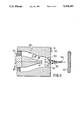
- FIG. 7 is a cross-sectional view of the ultrasonic nozzle of FIG. 3 with the downstream end of the transformer positioned downstream of the nozzle orifice.
- FIG. 1 With reference to FIG. 1, there is shown a non-vibratory nozzle of known configuration for generating cavitation bubbles in a high speed liquid jet.
- the nozzle consists of an outer body 50 including a velocity increasing constriction 51 opening outwardly through an orifice 52.
- a centre body 53 is placed in the flow path of the fluid stream so that its downstream end 56 is located immediately adjacent orifice 52. Cavitation bubbles 60 are most likely generated in the low pressure area 57 immediately downstream of end 56.
- Placing target surface 75 at the correct distance x from the point where the cavitation bubbles are generated is important so that the bubbles collapse substantially simultaneously with their impingement onto the surface for maximum amplification of the stream's erosive effect when compared to the cutting action of an unmodulated jet without cavitation or pulsating slugs.
- a vibratory ultrasonic nozzle consists of a nozzle body 1 having an inlet 2 for pressurized water from high pressure pump 3, an orifice 5 through which the high velocity fluid jet discharges towards the surface to be eroded, and a centre body or transformer 7 disposed along the longitudinal axis of the nozzle.
- Transformer 7 is oscillated by means of an ultrasonic vibrator such as a piezoelectric or magnetostrictive transducer 12 and its associated signal generator and amplifier 13.
- the objective is to produce high intensity sonic fields in the region between constrictions 20 and 21 by causing transformer 7 to vibrate inside the nozzle. This can be accomplished by properly designing the transformer to focus the ultrasonic energy from transducer 12, as will be described below.
- Velocity of flow in the nozzle depends on the shape of the nozzle, the size of the orifice 5 and pressure from pump 3. Ambient pressure P 0 between constriction 20 and orifice 5 changes due to hydraulic friction and velocity of the flow. For some nozzle designs, a uniform velocity of flow can be assumed, therefore the ambient pressure between constriction 20 and orifice 5 is a function of the length of coordinate x and friction within the nozzle. To produce cavitation, the acoustic pressure P a generated by transformer 7 should be at least 1.1 and up to 6 times higher than the ambient pressure P 0 .
- the ultrasonic nozzle will produce high speed slugs or cavitation bubbles will depend largely upon nozzle geometry, the shape and placement of the transformer relative to the nozzle orifice and the power and frequency of the ultrasonic waves induced by the transformer.
- FIGS. 3 and 4 showing applicant's novel nozzles for producing, in the case of the nozzle of FIG. 3, predominantly high speed water slugs, and cavitation bubbles in the case of the nozzle shown in FIG. 4.
- FIG. 3 there is shown a converging nozzle 30 for generating predominantly slugs in high speed water jets.
- Nozzle 30 consists of a nozzle body 31 having a flow channel 32 formed therethrough.
- the shape of channel 32 may vary in the longitudinal direction of flow, but transversely, the channel is typically circular or near-circular in shape along its entire length.
- Pressurized fluid 35 (usually water) pumped through the nozzle will discharge through orifice 36 against the surface 37 of a material to be eroded.
- Axially aligned within channel 32 is a transformer 38 connected at its upstream end to an ultrasonic vibrator 29 such as a piezoelectric or magnetostriction transducer.
- the longitudinal cross-sectional profile of transformer 38 may take different shapes, examples of which are shown in FIG. 6. Acceptable profiles include stepped down cylinders, simple frusto-cones or exponential, catenoidal or Fourier curves all as shown in FIG. 6. The preferred profile of the transformer is exponential or catenoidal.
- R radius of the profile at any distance x from the root
- R 0 radius of the profile at the root
- R t radius of the profile at the tip
- the equation for the Fourier profile consists of a series of sine or cosine functions.
- the axial cross-sectional shape of channel 32 is chosen to conform to the longitudinal profile of transformer 38 as shown in FIG. 3.
- the width of the annulus 28 between transformer 38 and peripheral wall 39 of channel 32 remains constant along the length of the transformer to its downstream end 41.
- Orifice 36 is essentially cylindrical in longitudinal cross-sectional shape and in one embodiment constructed by the applicant in which the total liquid flow from the pump is 76 liters per minute, its diameter can vary depending on the operating pressure, from 1.96 mm (at 138 MPa) to 4.16 mm (at 6.9 MPa).
- the diameter of orifice 36 will henceforth be referred to as the nozzle diameter in relation to the embodiment of FIG. 3.
- the nozzle as shown produces predominantly slugs of water due to its design wherein the converging section of the nozzle terminates in a substantially cylindrical portion 33 with parallel side walls. In this environment, cavitation bubbles will have insufficient time to grow, particularly as tip 41 of transformer 38 can be adjusted to be located just downstream as shown in FIG.
- the distance L between tip 41 and exit plane 42 of orifice 36 may vary in the range between 5 nozzle diameters upstream and 1 nozzle diameter downstream of said exit plane (e.g., 20.8 mm upstream to 1.96 mm downstream of said exit plane, depending upon the operating pressure and orifice diameter chosen).
- Concavity 43 may be hemi-spherical in shape or may define a less severe arc, the curvature of which is a function of the arc's radius. Concavity 43 greatly increases the power density within the nozzle immediately downstream of the transformer to yield ultra high speed pulses or slugs of water. The rate at which the pulses are formed and their size can be controlled by respectively varying the frequency and amplitude of the ultrasonic vibrations generated by the transformer.
- nozzle 30 is fabricated or otherwise made of from 17-4 Ph stainless steel having a Rockwell hardness of 45 (C scale).
- Vibrator 29 is driven by a 1 kw transducer operable at a frequency between 0 and 10 kHz. Fluid discharge velocity at orifice 36 is variable to a maximum of approximately 1500 feet per second.
- FIG. 4 there is shown a variation of the present nozzle including an adaptation designed to promote cavitation within the nozzle.
- like reference numerals have been used to identify like elements to those appearing in FIG. 3.
- the profile of the transformer and the flow channel conform to one another proceeding in the direction of flow to the end of transformer 38 at tip 41. At that point, the nozzle forms a substantially cylindrical constricted throat 50 and begins to diverge until exiting at orifice 36.
- the rate of divergence measured as an angle ⁇ between longitudinal axis 53 and peripheral wall 39 varies between 2° and 10°.
- the upstream distance L between tip 41 and exit plane 42 of the orifice 36 will vary between 5 to 50 throat diameters (+9.8 mm to 104 mm, depending on the operating pressure and the throat diameter chosen) depending upon the desired bubble intensity.
- the diameter of throat 50 in one embodiment constructed by the applicant in which the total liquid flow from the pump is 76 liters/min., can vary, depending on the operating pressure, from 1.96 mm (at 138 MPa) to 4.16 mm (at 6.9 MPa).
- the distance D between the orifice and the surface to be eroded or cut will typically fall in the range from 2.5 mm to 200 mm, the latter being the distance from orifice 36 beyond which cavitating jets will be generally ineffective.
- Transformer 38 is located such that the energy in the ultrasonic waves generated thereby is focused by means of the concavity 43 adjacent throat 50 of the nozzle, this being a zone of minimum pressure within the nozzle and therefore the environment most conducive to formation of the bubbles.
- Bubble population and bubble size can be controlled by varying the frequency (0 to 10 kHz) and amplitude (to a maximum of 1/2 mm) of the ultrasonic waves produced by the transformer, and adjustments to the distance L. Bubble population will in turn control erosive intensity.
- cavitating jets are far more effective when discharged under submerged conditions rather than in air.
- the cavitation bubbles 80 are completely surrounded by an annular stream of water 82 which emulates a submerged discharge. The nozzle will therefore operate effectively whether used in ambient atmospheric or under submerged conditions.
- solid metallic transformers are used.
- the transformers should provide a suitable impedance matched between the transducer and the load to which it is to be coupled. Maximum output of the transformer is limited by the fatigue strength of the metal (stainless steel, nickel or nickel alloy) used to make the same.
- the curved transformers produce the desired modulations with much lower stress as compared to the stepped or simple conical transformers.
- a faster, augmented jet having a velocity V fj is formed, followed by a slower jet.
- the augmentation factor equals V fj /V 0 and depends upon, amongst other factors, the shape of the converging slugs and the angle of convergence of the streams. In some instances, velocity augmentation by a factor of 10 can be achieved to greatly intensify the erosive effect. More typically, augmentation factors vary in the range of 3 to 10.
- a pair of converging nozzles 90 are formed to cause slugs 92 travelling at velocity V 0 to collide resulting in fast jet 94 having a velocity V fj .
- the angle of convergence between the two streams may vary in the range of 10° to 60°.
- the nozzle of FIG. 5 is substantially the same as the nozzles of FIGS. 3 and 4 with the exception that no concavity need be formed at the tip of the transformer as it is obviously unnecessary to focus the transformer's ultrasonic energy for fluid discharge in axial alignment therewith.
Abstract
Description
R=R.sub.0 e.sup.-kx
R=R.sub.0 cosh.sub.2 b(L-x)
Claims (34)
Applications Claiming Priority (2)
| Application Number | Priority Date | Filing Date | Title |
|---|---|---|---|
| CA002035702A CA2035702C (en) | 1991-02-05 | 1991-02-05 | Ultrasonically generated cavitating or interrupted jet |
| CA2035702 | 1991-02-05 |
Publications (1)
| Publication Number | Publication Date |
|---|---|
| US5154347A true US5154347A (en) | 1992-10-13 |
Family
ID=4146959
Family Applications (1)
| Application Number | Title | Priority Date | Filing Date |
|---|---|---|---|
| US07/672,217 Expired - Fee Related US5154347A (en) | 1991-02-05 | 1991-03-20 | Ultrasonically generated cavitating or interrupted jet |
Country Status (4)
| Country | Link |
|---|---|
| US (1) | US5154347A (en) |
| AU (1) | AU1221792A (en) |
| CA (1) | CA2035702C (en) |
| WO (1) | WO1992013679A1 (en) |
Cited By (48)
| Publication number | Priority date | Publication date | Assignee | Title |
|---|---|---|---|---|
| US5305361A (en) * | 1992-01-24 | 1994-04-19 | Hitachi, Ltd. | Method of and apparatus for water-jet peening |
| US5560543A (en) * | 1994-09-19 | 1996-10-01 | Board Of Regents, The University Of Texas System | Heat-resistant broad-bandwidth liquid droplet generators |
| US6053424A (en) * | 1995-12-21 | 2000-04-25 | Kimberly-Clark Worldwide, Inc. | Apparatus and method for ultrasonically producing a spray of liquid |
| US6200486B1 (en) | 1999-04-02 | 2001-03-13 | Dynaflow, Inc. | Fluid jet cavitation method and system for efficient decontamination of liquids |
| US6221260B1 (en) | 1999-04-02 | 2001-04-24 | Dynaflow, Inc. | Swirling fluid jet cavitation method and system for efficient decontamination of liquids |
| US6241162B1 (en) * | 1999-06-23 | 2001-06-05 | Kaijo Corporation | Ultrasonic shower cleaning apparatus |
| US6380264B1 (en) * | 1994-06-23 | 2002-04-30 | Kimberly-Clark Corporation | Apparatus and method for emulsifying a pressurized multi-component liquid |
| US6395216B1 (en) | 1994-06-23 | 2002-05-28 | Kimberly-Clark Worldwide, Inc. | Method and apparatus for ultrasonically assisted melt extrusion of fibers |
| US6405794B1 (en) * | 1999-03-07 | 2002-06-18 | Korea Institute Of Science And Technology | Acoustic convection apparatus |
| US6450417B1 (en) | 1995-12-21 | 2002-09-17 | Kimberly-Clark Worldwide Inc. | Ultrasonic liquid fuel injection apparatus and method |
| WO2003022451A1 (en) * | 2001-09-07 | 2003-03-20 | Kimberly-Clark Worldwide, Inc. | Ultrasonic apparatus and method to improve the flow of viscous liquids |
| US6543700B2 (en) | 2000-12-11 | 2003-04-08 | Kimberly-Clark Worldwide, Inc. | Ultrasonic unitized fuel injector with ceramic valve body |
| US6555002B2 (en) | 2000-10-06 | 2003-04-29 | Premier Wastwater International, Llc | Apparatus and method for wastewater treatment with enhanced solids reduction (ESR) |
| US6663027B2 (en) | 2000-12-11 | 2003-12-16 | Kimberly-Clark Worldwide, Inc. | Unitized injector modified for ultrasonically stimulated operation |
| US20040074979A1 (en) * | 2002-10-16 | 2004-04-22 | Mcguire Dennis | High impact waterjet nozzle |
| WO2005042177A1 (en) * | 2003-11-03 | 2005-05-12 | Vln Advanced Technologies Inc. | Ultrasonic waterjet apparatus |
| WO2006097887A1 (en) * | 2005-03-15 | 2006-09-21 | Institute Of Geonics, Ascr | Method of generation of pressure pulsations and apparatus for implementation of this method |
| US20090003123A1 (en) * | 2007-06-28 | 2009-01-01 | Morrison Jr Lowen Robert | Apparatus and method for mixing by producing shear and/or cavitation, and components for apparatus |
| US20090056399A1 (en) * | 2007-08-29 | 2009-03-05 | Hisamitu Hatou | method for executing water jet peening |
| US20090121038A1 (en) * | 2005-05-06 | 2009-05-14 | Dieter Wurz | Spray nozzle, spray device and method for operating a spray nozzle and a spray device |
| US20090140067A1 (en) * | 2007-11-29 | 2009-06-04 | Vedanth Srinivasan | Devices and Methods for Atomizing Fluids |
| US20090200394A1 (en) * | 2008-02-08 | 2009-08-13 | Eilaz Babaev | Echoing ultrasound atomization and mixing system |
| US7607470B2 (en) | 2005-11-14 | 2009-10-27 | Nuventix, Inc. | Synthetic jet heat pipe thermal management system |
| EP2145689A1 (en) | 2008-07-16 | 2010-01-20 | VLN Advanced Technologies Inc. | Method and apparatus for prepping surfaces with a high-frequency forced pulsed waterjet |
| EP2196285A1 (en) * | 2008-12-11 | 2010-06-16 | Nederlandse Organisatie voor toegepast-natuurwetenschappelijk Onderzoek TNO | Method and apparatus for polishing a workpiece surface |
| CN101905207A (en) * | 2010-09-03 | 2010-12-08 | 任保林 | Vortex pulse resonance jet spray head device |
| US20100324481A1 (en) * | 2007-07-13 | 2010-12-23 | Bacoustics, Llc | Ultrasound pumping apparatus for use with the human body |
| WO2011042244A2 (en) | 2009-10-06 | 2011-04-14 | Sulzer Metco (Us) Inc. | Method and apparatus for preparation of cylinder bore surfaces for thermal spray coating with pulsed waterjet |
| US8030886B2 (en) | 2005-12-21 | 2011-10-04 | Nuventix, Inc. | Thermal management of batteries using synthetic jets |
| EP2377967A1 (en) | 2010-04-13 | 2011-10-19 | VLN Advanced Technologies Inc. | Method and apparatus for prepping a surface using a coating particle entrained in a continuous or pulsed waterjet or airjet |
| CN102574169A (en) * | 2009-08-26 | 2012-07-11 | 南安普敦大学 | Cleaning apparatus and method, and monitoring thereof |
| EP2529843A2 (en) | 2011-05-31 | 2012-12-05 | VLN Advanced Technologies Inc. | Reverse-flow nozzle for generating cavitating or pulsed jets |
| WO2013020732A1 (en) * | 2011-08-11 | 2013-02-14 | Dürr Ecoclean GmbH | Device for generating a pulsating fluid jet subjected to pressure |
| US8505583B2 (en) | 2010-07-12 | 2013-08-13 | Gene G. Yie | Method and apparatus for generating high-speed pulsed fluid jets |
| US20140116217A1 (en) * | 2012-10-31 | 2014-05-01 | Flow International Corporation | Fluid distribution components of high-pressure fluid jet systems |
| EP2871002A1 (en) | 2013-11-08 | 2015-05-13 | VLN Advanced Technologies Inc. | Integrated fluidjet system for stripping, prepping and coating a part |
| US20160053544A1 (en) * | 2013-04-08 | 2016-02-25 | Schwindt Hydraulik Gmbh | Method for the chisel-less formation of boreholes for deep bores and chisel-less drilling system for carrying out said method |
| WO2016091447A1 (en) * | 2014-12-09 | 2016-06-16 | Robert Bosch Gmbh | Method for liquid-jet cutting |
| US9381663B2 (en) | 2013-02-21 | 2016-07-05 | Microwaterjet Ag | Method for drilling at least one hole into a workpiece |
| CN107000239A (en) * | 2014-12-15 | 2017-08-01 | 罗伯特·博世有限公司 | The method cut for liquid jet |
| WO2019202299A1 (en) * | 2018-04-20 | 2019-10-24 | Zeeko Innovations Limited | Fluid jet processing |
| US10502014B2 (en) * | 2017-05-03 | 2019-12-10 | Coil Solutions, Inc. | Extended reach tool |
| US10589400B2 (en) | 2014-01-15 | 2020-03-17 | Flow International Corporation | High-pressure waterjet cutting head systems, components and related methods |
| US10596717B2 (en) | 2015-07-13 | 2020-03-24 | Flow International Corporation | Methods of cutting fiber reinforced polymer composite workpieces with a pure waterjet |
| CN113967547A (en) * | 2021-11-09 | 2022-01-25 | 中铁工程装备集团有限公司 | Injection device |
| US11399862B2 (en) | 2019-06-24 | 2022-08-02 | Boston Scientific Scimed, Inc. | Propulsion system for inertial energy transfer to disrupt vascular lesions |
| US11479035B2 (en) * | 2016-08-30 | 2022-10-25 | Jetronica Limited | Industrial printhead |
| US11950799B2 (en) | 2022-06-23 | 2024-04-09 | Boston Scientific Scimed, Inc. | Propulsion system for inertial energy transfer to disrupt vascular lesions |
Families Citing this family (8)
| Publication number | Priority date | Publication date | Assignee | Title |
|---|---|---|---|---|
| FR2715884B1 (en) * | 1994-02-04 | 1996-04-12 | Gec Alsthom Electromec | Method and device for the surface treatment and the prestressing of the interior wall of a cavity. |
| FR2731935B1 (en) * | 1995-03-23 | 1997-07-04 | Belmokadem Marie | DEVICE FOR DEVELOPING RESIDUAL COMPRESSION CONSTRAINTS ON THE SURFACE OF A SOLID MATERIAL |
| DE19529749C2 (en) * | 1995-08-12 | 1997-11-20 | Ot Oberflaechentechnik Gmbh | Process for the layer-by-layer removal of material from the surface of a workpiece and device for carrying out this process |
| JP4428014B2 (en) | 2003-02-25 | 2010-03-10 | パナソニック電工株式会社 | Ultrasonic biological cleaning equipment |
| CZ302595B6 (en) * | 2010-07-29 | 2011-07-27 | Hydrosystem Project A.S. | Device to create and intensify modulation of liquid flow velocity |
| CA2999011C (en) | 2017-03-24 | 2020-04-21 | Vln Advanced Technologies Inc. | Compact ultrasonically pulsed waterjet nozzle |
| CN112112569B (en) * | 2020-09-07 | 2023-05-02 | 中石化石油机械股份有限公司 | Oscillating slide vane jet flow increasing Cheng Shuili oscillator |
| CN112974004B (en) * | 2021-02-09 | 2022-08-09 | 华东理工大学 | Jet nozzle for strengthening surface of limited part of aviation component |
Citations (11)
| Publication number | Priority date | Publication date | Assignee | Title |
|---|---|---|---|---|
| US3368085A (en) * | 1965-11-19 | 1968-02-06 | Trustees Of The Ohio State Uni | Sonic transducer |
| US3373752A (en) * | 1962-11-13 | 1968-03-19 | Inoue Kiyoshi | Method for the ultrasonic cleaning of surfaces |
| US3528704A (en) * | 1968-07-17 | 1970-09-15 | Hydronautics | Process for drilling by a cavitating fluid jet |
| US3713699A (en) * | 1971-08-26 | 1973-01-30 | Hydronautics | System for eroding solids with a cavitating fluid jet |
| US3807632A (en) * | 1971-08-26 | 1974-04-30 | Hydronautics | System for eroding solids with a cavitating fluid jet |
| GB1462371A (en) * | 1973-02-20 | 1977-01-26 | Dobson Park Ind | Mining method and apparatus |
| US4262757A (en) * | 1978-08-04 | 1981-04-21 | Hydronautics, Incorporated | Cavitating liquid jet assisted drill bit and method for deep-hole drilling |
| US4474251A (en) * | 1980-12-12 | 1984-10-02 | Hydronautics, Incorporated | Enhancing liquid jet erosion |
| US4787465A (en) * | 1986-04-18 | 1988-11-29 | Ben Wade Oakes Dickinson Iii Et Al. | Hydraulic drilling apparatus and method |
| US4850440A (en) * | 1986-08-13 | 1989-07-25 | Smet Nic H W | Method and device for making a hole in the ground |
| US4852668A (en) * | 1986-04-18 | 1989-08-01 | Ben Wade Oakes Dickinson, III | Hydraulic drilling apparatus and method |
Family Cites Families (3)
| Publication number | Priority date | Publication date | Assignee | Title |
|---|---|---|---|---|
| FR978290A (en) * | 1948-12-29 | 1951-04-11 | Method and device for stripping or other surface actions | |
| US4337899A (en) * | 1980-02-25 | 1982-07-06 | The Curators Of The University Of Missouri | High pressure liquid jet nozzle system for enhanced mining and drilling |
| US4930701A (en) * | 1987-09-08 | 1990-06-05 | Mcdonnell Douglas Corporation | Confluent nozzle |
-
1991
- 1991-02-05 CA CA002035702A patent/CA2035702C/en not_active Expired - Fee Related
- 1991-03-20 US US07/672,217 patent/US5154347A/en not_active Expired - Fee Related
-
1992
- 1992-02-05 WO PCT/CA1992/000047 patent/WO1992013679A1/en active Application Filing
- 1992-02-05 AU AU12217/92A patent/AU1221792A/en not_active Abandoned
Patent Citations (11)
| Publication number | Priority date | Publication date | Assignee | Title |
|---|---|---|---|---|
| US3373752A (en) * | 1962-11-13 | 1968-03-19 | Inoue Kiyoshi | Method for the ultrasonic cleaning of surfaces |
| US3368085A (en) * | 1965-11-19 | 1968-02-06 | Trustees Of The Ohio State Uni | Sonic transducer |
| US3528704A (en) * | 1968-07-17 | 1970-09-15 | Hydronautics | Process for drilling by a cavitating fluid jet |
| US3713699A (en) * | 1971-08-26 | 1973-01-30 | Hydronautics | System for eroding solids with a cavitating fluid jet |
| US3807632A (en) * | 1971-08-26 | 1974-04-30 | Hydronautics | System for eroding solids with a cavitating fluid jet |
| GB1462371A (en) * | 1973-02-20 | 1977-01-26 | Dobson Park Ind | Mining method and apparatus |
| US4262757A (en) * | 1978-08-04 | 1981-04-21 | Hydronautics, Incorporated | Cavitating liquid jet assisted drill bit and method for deep-hole drilling |
| US4474251A (en) * | 1980-12-12 | 1984-10-02 | Hydronautics, Incorporated | Enhancing liquid jet erosion |
| US4787465A (en) * | 1986-04-18 | 1988-11-29 | Ben Wade Oakes Dickinson Iii Et Al. | Hydraulic drilling apparatus and method |
| US4852668A (en) * | 1986-04-18 | 1989-08-01 | Ben Wade Oakes Dickinson, III | Hydraulic drilling apparatus and method |
| US4850440A (en) * | 1986-08-13 | 1989-07-25 | Smet Nic H W | Method and device for making a hole in the ground |
Non-Patent Citations (2)
| Title |
|---|
| Ashley s Study of an Ultrasonically Generated Cavitating or Interrupted Jet: Aspects of Design, M.M.V.J., Paper B2, Jet Cutting Technology, Jun. 26 28, 1984. * |
| Ashley's Study of an Ultrasonically Generated Cavitating or Interrupted Jet: Aspects of Design, M.M.V.J., Paper B2, Jet Cutting Technology, Jun. 26-28, 1984. |
Cited By (104)
| Publication number | Priority date | Publication date | Assignee | Title |
|---|---|---|---|---|
| US5305361A (en) * | 1992-01-24 | 1994-04-19 | Hitachi, Ltd. | Method of and apparatus for water-jet peening |
| US6380264B1 (en) * | 1994-06-23 | 2002-04-30 | Kimberly-Clark Corporation | Apparatus and method for emulsifying a pressurized multi-component liquid |
| US6395216B1 (en) | 1994-06-23 | 2002-05-28 | Kimberly-Clark Worldwide, Inc. | Method and apparatus for ultrasonically assisted melt extrusion of fibers |
| US5560543A (en) * | 1994-09-19 | 1996-10-01 | Board Of Regents, The University Of Texas System | Heat-resistant broad-bandwidth liquid droplet generators |
| US5810988A (en) * | 1994-09-19 | 1998-09-22 | Board Of Regents, University Of Texas System | Apparatus and method for generation of microspheres of metals and other materials |
| US6053424A (en) * | 1995-12-21 | 2000-04-25 | Kimberly-Clark Worldwide, Inc. | Apparatus and method for ultrasonically producing a spray of liquid |
| US6315215B1 (en) | 1995-12-21 | 2001-11-13 | Kimberly-Clark Worldwide, Inc. | Apparatus and method for ultrasonically self-cleaning an orifice |
| US6450417B1 (en) | 1995-12-21 | 2002-09-17 | Kimberly-Clark Worldwide Inc. | Ultrasonic liquid fuel injection apparatus and method |
| US6659365B2 (en) | 1995-12-21 | 2003-12-09 | Kimberly-Clark Worldwide, Inc. | Ultrasonic liquid fuel injection apparatus and method |
| US6405794B1 (en) * | 1999-03-07 | 2002-06-18 | Korea Institute Of Science And Technology | Acoustic convection apparatus |
| US6221260B1 (en) | 1999-04-02 | 2001-04-24 | Dynaflow, Inc. | Swirling fluid jet cavitation method and system for efficient decontamination of liquids |
| US6200486B1 (en) | 1999-04-02 | 2001-03-13 | Dynaflow, Inc. | Fluid jet cavitation method and system for efficient decontamination of liquids |
| US6241162B1 (en) * | 1999-06-23 | 2001-06-05 | Kaijo Corporation | Ultrasonic shower cleaning apparatus |
| USRE40512E1 (en) * | 1999-06-23 | 2008-09-23 | Samsung Electronics Co., Ltd. | Acoustic convection apparatus |
| US20040007523A1 (en) * | 2000-10-06 | 2004-01-15 | Premier Wastewater International, Llc | Apparatus and method for wastewater treatment with enhanced solids reduction (ESR) |
| US6605220B2 (en) | 2000-10-06 | 2003-08-12 | Premier Wastewater International, Inc. | Apparatus and method for wastewater treatment with enhanced solids reduction (ESR) |
| US6555002B2 (en) | 2000-10-06 | 2003-04-29 | Premier Wastwater International, Llc | Apparatus and method for wastewater treatment with enhanced solids reduction (ESR) |
| US6663027B2 (en) | 2000-12-11 | 2003-12-16 | Kimberly-Clark Worldwide, Inc. | Unitized injector modified for ultrasonically stimulated operation |
| US6543700B2 (en) | 2000-12-11 | 2003-04-08 | Kimberly-Clark Worldwide, Inc. | Ultrasonic unitized fuel injector with ceramic valve body |
| US20040016831A1 (en) * | 2000-12-11 | 2004-01-29 | Jameson Lee Kirby | Method of retrofitting an unitized injector for ultrasonically stimulated operation |
| US6880770B2 (en) | 2000-12-11 | 2005-04-19 | Kimberly-Clark Worldwide, Inc. | Method of retrofitting an unitized injector for ultrasonically stimulated operation |
| WO2003022451A1 (en) * | 2001-09-07 | 2003-03-20 | Kimberly-Clark Worldwide, Inc. | Ultrasonic apparatus and method to improve the flow of viscous liquids |
| US20040074979A1 (en) * | 2002-10-16 | 2004-04-22 | Mcguire Dennis | High impact waterjet nozzle |
| US7100844B2 (en) | 2002-10-16 | 2006-09-05 | Ultrastrip Systems, Inc. | High impact waterjet nozzle |
| US8006915B2 (en) | 2003-11-03 | 2011-08-30 | Vijay Mohan M | Ultrasonic waterjet apparatus |
| US7594614B2 (en) | 2003-11-03 | 2009-09-29 | Vln Advanced Technologies, Inc. | Ultrasonic waterjet apparatus |
| JP2007523751A (en) * | 2003-11-03 | 2007-08-23 | ヴィーエルエヌ アドヴァンスト テクノロジーズ インコーポレイテッド | Ultrasonic water jet device |
| US20070063066A1 (en) * | 2003-11-03 | 2007-03-22 | Nortel Networks Limited | Ultrasonic waterjet apparatus |
| US8387894B2 (en) | 2003-11-03 | 2013-03-05 | Pratt & Whitney Military Aftermarket Services, Inc. | Ultrasonic waterjet apparatus |
| US8360337B2 (en) | 2003-11-03 | 2013-01-29 | Pratt & Whitney Military Aftermarket Services, Inc. | Ultrasonic waterjet apparatus |
| WO2005042177A1 (en) * | 2003-11-03 | 2005-05-12 | Vln Advanced Technologies Inc. | Ultrasonic waterjet apparatus |
| JP4718327B2 (en) * | 2003-11-03 | 2011-07-06 | ヴィーエルエヌ アドヴァンスト テクノロジーズ インコーポレイテッド | Ultrasonic water jet device |
| US20110089251A1 (en) * | 2003-11-03 | 2011-04-21 | Vln Advanced Technologies, Inc. | Ultrasonic Waterjet Apparatus |
| CZ301715B6 (en) * | 2003-11-03 | 2010-06-02 | Vln Advanced Technologies Inc. | Ultrasonic waterjet apparatus and method of generating pulsed waterjet |
| US20090308948A1 (en) * | 2003-11-03 | 2009-12-17 | Vln Advanced Technologies, Inc. | Ultrasonic Waterjet Apparatus |
| US20100155502A1 (en) * | 2005-03-15 | 2010-06-24 | Institute Of Geonics Ascr, V.V.I. | Method of generation of pressure pulsations and apparatus for implementation of this method |
| US20080135638A1 (en) * | 2005-03-15 | 2008-06-12 | Josef Foldyna | Method of Generation of Pressure Pulsations and Apparatus For Implementation of This Method |
| CZ299412B6 (en) * | 2005-03-15 | 2008-07-16 | Ústav geoniky AV CR, v.v.i. | Method of generating pressure pulses and apparatus for making the same |
| WO2006097887A1 (en) * | 2005-03-15 | 2006-09-21 | Institute Of Geonics, Ascr | Method of generation of pressure pulsations and apparatus for implementation of this method |
| AU2006224192B2 (en) * | 2005-03-15 | 2012-05-31 | Institute Of Geonics, Ascr | Method of generation of pressure pulsations and apparatus for implementation of this method |
| US7740188B2 (en) * | 2005-03-15 | 2010-06-22 | Institute Of Geonics, Ascr, V.V.I. | Method of generation of pressure pulsations and apparatus for implementation of this method |
| US7934666B2 (en) * | 2005-03-15 | 2011-05-03 | Institute Of Geonics Ascr, V.V.I. | Method of generation of pressure pulsations and apparatus for implementation of this method |
| US20090121038A1 (en) * | 2005-05-06 | 2009-05-14 | Dieter Wurz | Spray nozzle, spray device and method for operating a spray nozzle and a spray device |
| US8985478B2 (en) | 2005-05-06 | 2015-03-24 | Dieter Wurz | Spray nozzle, spray device and method for operating a spray nozzle and a spray device |
| US8453945B2 (en) * | 2005-05-06 | 2013-06-04 | Dieter Wurz | Spray nozzle, spray device and method for operating a spray nozzle and a spray device |
| US7607470B2 (en) | 2005-11-14 | 2009-10-27 | Nuventix, Inc. | Synthetic jet heat pipe thermal management system |
| US8030886B2 (en) | 2005-12-21 | 2011-10-04 | Nuventix, Inc. | Thermal management of batteries using synthetic jets |
| US20090003123A1 (en) * | 2007-06-28 | 2009-01-01 | Morrison Jr Lowen Robert | Apparatus and method for mixing by producing shear and/or cavitation, and components for apparatus |
| US8517595B2 (en) * | 2007-06-28 | 2013-08-27 | The Procter & Gamble Company | Apparatus and method for mixing by producing shear and/or cavitation, and components for apparatus |
| US20100324481A1 (en) * | 2007-07-13 | 2010-12-23 | Bacoustics, Llc | Ultrasound pumping apparatus for use with the human body |
| US20090056399A1 (en) * | 2007-08-29 | 2009-03-05 | Hisamitu Hatou | method for executing water jet peening |
| US7716961B2 (en) * | 2007-08-29 | 2010-05-18 | Hitachi-Ge Nuclear Energy, Ltd. | Method for executing water jet peening |
| US20090140067A1 (en) * | 2007-11-29 | 2009-06-04 | Vedanth Srinivasan | Devices and Methods for Atomizing Fluids |
| US7617993B2 (en) * | 2007-11-29 | 2009-11-17 | Toyota Motor Corporation | Devices and methods for atomizing fluids |
| US8016208B2 (en) * | 2008-02-08 | 2011-09-13 | Bacoustics, Llc | Echoing ultrasound atomization and mixing system |
| US20090200394A1 (en) * | 2008-02-08 | 2009-08-13 | Eilaz Babaev | Echoing ultrasound atomization and mixing system |
| US9757756B2 (en) | 2008-07-16 | 2017-09-12 | Vln Advanced Technologies Inc. | Method and apparatus for prepping bores and curved inner surfaces with a rotating high-frequencey forced pulsed waterjet |
| US10189046B2 (en) | 2008-07-16 | 2019-01-29 | Vln Advanced Technologies Inc. | Method and apparatus for prepping bores and curved inner surfaces with a rotating high-frequency forced pulsed waterjet |
| EP2540402A2 (en) | 2008-07-16 | 2013-01-02 | VLN Advanced Technologies Inc. | Method and apparatus for prepping surfaces with a high-frequency forced pulsed waterjet |
| EP2540401A2 (en) | 2008-07-16 | 2013-01-02 | VLN Advanced Technologies Inc. | Method and apparatus for prepping surfaces with a high-frequency forced pulsed waterjet |
| EP3357583A1 (en) | 2008-07-16 | 2018-08-08 | VLN Advanced Technologies Inc. | Method and apparatus for prepping surfaces with a high-frequency forced pulsed waterjet |
| US20100015892A1 (en) * | 2008-07-16 | 2010-01-21 | Vln Advanced Technologies Inc. | Method and apparatus for prepping surfaces with a high-frequency forced pulsed waterjet |
| EP2145689A1 (en) | 2008-07-16 | 2010-01-20 | VLN Advanced Technologies Inc. | Method and apparatus for prepping surfaces with a high-frequency forced pulsed waterjet |
| US8550873B2 (en) | 2008-07-16 | 2013-10-08 | Vln Advanced Technologies Inc. | Method and apparatus for prepping surfaces with a high-frequency forced pulsed waterjet |
| US10532373B2 (en) | 2008-07-16 | 2020-01-14 | Vln Advanced Technologies Inc. | Method and apparatus for prepping bores and curved inner surfaces with a rotating high-frequency forced pulsed waterjet |
| EP2196285A1 (en) * | 2008-12-11 | 2010-06-16 | Nederlandse Organisatie voor toegepast-natuurwetenschappelijk Onderzoek TNO | Method and apparatus for polishing a workpiece surface |
| CN102574169A (en) * | 2009-08-26 | 2012-07-11 | 南安普敦大学 | Cleaning apparatus and method, and monitoring thereof |
| CN102574169B (en) * | 2009-08-26 | 2016-08-03 | 南安普敦大学 | A kind of devices and methods therefor for cleaning surface |
| CN102958616A (en) * | 2009-10-06 | 2013-03-06 | 苏舍美特科(美国)公司 | Method and apparatus for preparation of cylinder bore surfaces with a pulsed waterjet |
| WO2011042244A2 (en) | 2009-10-06 | 2011-04-14 | Sulzer Metco (Us) Inc. | Method and apparatus for preparation of cylinder bore surfaces for thermal spray coating with pulsed waterjet |
| CN102958616B (en) * | 2009-10-06 | 2016-06-01 | 苏舍美特科(美国)公司 | Utilize the method and apparatus that pulsing jet prepares cylinder-bore surface for thermally sprayed coating |
| EP2377967A1 (en) | 2010-04-13 | 2011-10-19 | VLN Advanced Technologies Inc. | Method and apparatus for prepping a surface using a coating particle entrained in a continuous or pulsed waterjet or airjet |
| US8505583B2 (en) | 2010-07-12 | 2013-08-13 | Gene G. Yie | Method and apparatus for generating high-speed pulsed fluid jets |
| CN101905207A (en) * | 2010-09-03 | 2010-12-08 | 任保林 | Vortex pulse resonance jet spray head device |
| EP2529843A2 (en) | 2011-05-31 | 2012-12-05 | VLN Advanced Technologies Inc. | Reverse-flow nozzle for generating cavitating or pulsed jets |
| RU2608488C2 (en) * | 2011-08-11 | 2017-01-18 | Дюрр Экоклин Гмбх | Device to create fluid medium pulsating jet subjected to action of pressure |
| EP2741862B1 (en) * | 2011-08-11 | 2018-09-05 | Ecoclean GmbH | Device for generating a pulsating fluid jet subjected to pressure |
| US9914238B2 (en) | 2011-08-11 | 2018-03-13 | Ecoclean Gmbh | Apparatus for generating a pulsating pressurized fluid jet |
| WO2013020732A1 (en) * | 2011-08-11 | 2013-02-14 | Dürr Ecoclean GmbH | Device for generating a pulsating fluid jet subjected to pressure |
| US9844890B2 (en) | 2012-10-31 | 2017-12-19 | Flow International Corporation | Fluid distribution components of high-pressure fluid jet systems |
| US20140116217A1 (en) * | 2012-10-31 | 2014-05-01 | Flow International Corporation | Fluid distribution components of high-pressure fluid jet systems |
| US9272437B2 (en) * | 2012-10-31 | 2016-03-01 | Flow International Corporation | Fluid distribution components of high-pressure fluid jet systems |
| US9884403B2 (en) | 2013-02-21 | 2018-02-06 | Microwaterjet Ag | Machining arrangement for drilling at least one hole into a workpiece |
| US9381663B2 (en) | 2013-02-21 | 2016-07-05 | Microwaterjet Ag | Method for drilling at least one hole into a workpiece |
| US20160053544A1 (en) * | 2013-04-08 | 2016-02-25 | Schwindt Hydraulik Gmbh | Method for the chisel-less formation of boreholes for deep bores and chisel-less drilling system for carrying out said method |
| US10272468B2 (en) | 2013-11-08 | 2019-04-30 | Vln Advanced Technologies Inc. | Integrated fluidjet system for stripping, prepping and coating a part |
| US9718091B2 (en) | 2013-11-08 | 2017-08-01 | Vln Advanced Technologies Inc. | Integrated fluidjet system for stripping, prepping and coating a part |
| US9512531B2 (en) | 2013-11-08 | 2016-12-06 | Vln Advanced Technologies Inc. | Integrated fluidjet system for stripping, prepping and coating a part |
| US9821337B2 (en) | 2013-11-08 | 2017-11-21 | Vln Advanced Technologies Inc. | Integrated fluidjet system for stripping, prepping and coating a part |
| EP2871002A1 (en) | 2013-11-08 | 2015-05-13 | VLN Advanced Technologies Inc. | Integrated fluidjet system for stripping, prepping and coating a part |
| US10589400B2 (en) | 2014-01-15 | 2020-03-17 | Flow International Corporation | High-pressure waterjet cutting head systems, components and related methods |
| CN107000238B (en) * | 2014-12-09 | 2019-07-02 | 罗伯特·博世有限公司 | Method for liquid jet cutting |
| US10486325B2 (en) | 2014-12-09 | 2019-11-26 | Robert Bosch Gmbh | Method for liquid-jet cutting |
| WO2016091447A1 (en) * | 2014-12-09 | 2016-06-16 | Robert Bosch Gmbh | Method for liquid-jet cutting |
| CN107000238A (en) * | 2014-12-09 | 2017-08-01 | 罗伯特·博世有限公司 | The method cut for liquid jet |
| CN107000239A (en) * | 2014-12-15 | 2017-08-01 | 罗伯特·博世有限公司 | The method cut for liquid jet |
| US10596717B2 (en) | 2015-07-13 | 2020-03-24 | Flow International Corporation | Methods of cutting fiber reinforced polymer composite workpieces with a pure waterjet |
| US11292147B2 (en) | 2015-07-13 | 2022-04-05 | Flow International Corporation | Methods of cutting fiber reinforced polymer composite workpieces with a pure waterjet |
| US11479035B2 (en) * | 2016-08-30 | 2022-10-25 | Jetronica Limited | Industrial printhead |
| US10502014B2 (en) * | 2017-05-03 | 2019-12-10 | Coil Solutions, Inc. | Extended reach tool |
| WO2019202299A1 (en) * | 2018-04-20 | 2019-10-24 | Zeeko Innovations Limited | Fluid jet processing |
| US11399862B2 (en) | 2019-06-24 | 2022-08-02 | Boston Scientific Scimed, Inc. | Propulsion system for inertial energy transfer to disrupt vascular lesions |
| CN113967547A (en) * | 2021-11-09 | 2022-01-25 | 中铁工程装备集团有限公司 | Injection device |
| US11950799B2 (en) | 2022-06-23 | 2024-04-09 | Boston Scientific Scimed, Inc. | Propulsion system for inertial energy transfer to disrupt vascular lesions |
Also Published As
| Publication number | Publication date |
|---|---|
| CA2035702C (en) | 1996-10-01 |
| WO1992013679A1 (en) | 1992-08-20 |
| CA2035702A1 (en) | 1992-08-06 |
| AU1221792A (en) | 1992-09-07 |
Similar Documents
| Publication | Publication Date | Title |
|---|---|---|
| US5154347A (en) | Ultrasonically generated cavitating or interrupted jet | |
| US9011698B2 (en) | Method and devices for sonicating liquids with low-frequency high energy ultrasound | |
| US4389071A (en) | Enhancing liquid jet erosion | |
| JP3181221U (en) | Apparatus for implementing a method for generating pressure pulsations | |
| EP0062111A2 (en) | Enhancing liquid jet erosion | |
| US10189046B2 (en) | Method and apparatus for prepping bores and curved inner surfaces with a rotating high-frequency forced pulsed waterjet | |
| JP5611359B2 (en) | Method and apparatus for pretreating cylinder bore surfaces for thermal spray coating using a pulsed water jet | |
| CN102513237A (en) | Cavitation type ultrahigh pressure water hammer type water gun sprayer | |
| RU2376193C1 (en) | Method of hydrodynamic underwater cleaning of surfaces and related device | |
| CA2142971A1 (en) | Method and apparatus for generating high energy acoustic pulses | |
| Foldyna | Use of acoustic waves for pulsating water jet generation | |
| WO2014151243A1 (en) | Pulse cavitation processor and method of using same | |
| RU98111015A (en) | METHOD FOR UNDERWATER HYDRODYNAMIC CLEANING OF SHIP BOARDS AND DEVICE FOR ITS IMPLEMENTATION | |
| US10233097B2 (en) | Liquid treatment apparatus with ring vortex processor and method of using same | |
| CN220386850U (en) | Pulse cavitation jet nozzle device and jet generation system | |
| RU2785232C1 (en) | Device and method for hydrodynamic purification of surfaces of equipment, parts, and intervals in perforation in well | |
| RU2222463C2 (en) | Injector for underwater cleaning tool | |
| SU872663A1 (en) | Soil intake of dredge | |
| RU217875U1 (en) | DOWNHOLE HYDROMECHANICAL OSCILLATOR | |
| RU2168632C1 (en) | Method of liquid jet formation | |
| Foldyna | Pulsating Abrasive Water Jet Cutting Using a Standard Abrasive Injection Cutting Head–Preliminary Tests | |
| RU20899U1 (en) | HYDRODYNAMIC TURBOQUAVITOR NOZZLE FOR A JET CLEANING DEVICE | |
| Chahine et al. | Miami Beach, Flordia November 17-22, 1985 | |
| RU2307938C1 (en) | Liquid jet generation method and device | |
| CA2672441A1 (en) | Method and apparatus for prepping surfaces with a high-frequency forced pulsed waterjet |
Legal Events
| Date | Code | Title | Description |
|---|---|---|---|
| AS | Assignment |
Owner name: NATIONAL RESEARCH COUNCIL CANADA, MONTREAL ROAD, O Free format text: ASSIGNMENT OF ASSIGNORS INTEREST.;ASSIGNOR:VIJAY, MOHAN M.;REEL/FRAME:005645/0925 Effective date: 19910313 |
|
| FEPP | Fee payment procedure |
Free format text: PAYOR NUMBER ASSIGNED (ORIGINAL EVENT CODE: ASPN); ENTITY STATUS OF PATENT OWNER: LARGE ENTITY |
|
| FPAY | Fee payment |
Year of fee payment: 4 |
|
| FPAY | Fee payment |
Year of fee payment: 8 |
|
| REMI | Maintenance fee reminder mailed | ||
| LAPS | Lapse for failure to pay maintenance fees | ||
| LAPS | Lapse for failure to pay maintenance fees |
Free format text: PATENT EXPIRED FOR FAILURE TO PAY MAINTENANCE FEES (ORIGINAL EVENT CODE: EXP.); ENTITY STATUS OF PATENT OWNER: LARGE ENTITY |
|
| STCH | Information on status: patent discontinuation |
Free format text: PATENT EXPIRED DUE TO NONPAYMENT OF MAINTENANCE FEES UNDER 37 CFR 1.362 |
|
| FP | Lapsed due to failure to pay maintenance fee |
Effective date: 20041013 |