US5159532A - Electronic control unit with multiple hybrid circuit assemblies integrated on a single common ceramic carrier - Google Patents
Electronic control unit with multiple hybrid circuit assemblies integrated on a single common ceramic carrier Download PDFInfo
- Publication number
- US5159532A US5159532A US07/707,198 US70719891A US5159532A US 5159532 A US5159532 A US 5159532A US 70719891 A US70719891 A US 70719891A US 5159532 A US5159532 A US 5159532A
- Authority
- US
- United States
- Prior art keywords
- control unit
- heat sink
- electronic control
- circuit
- electronic
- Prior art date
- Legal status (The legal status is an assumption and is not a legal conclusion. Google has not performed a legal analysis and makes no representation as to the accuracy of the status listed.)
- Expired - Lifetime
Links
Images
Classifications
-
- H—ELECTRICITY
- H01—ELECTRIC ELEMENTS
- H01L—SEMICONDUCTOR DEVICES NOT COVERED BY CLASS H10
- H01L25/00—Assemblies consisting of a plurality of individual semiconductor or other solid state devices ; Multistep manufacturing processes thereof
- H01L25/16—Assemblies consisting of a plurality of individual semiconductor or other solid state devices ; Multistep manufacturing processes thereof the devices being of types provided for in two or more different main groups of groups H01L27/00 - H01L33/00, or in a single subclass of H10K, H10N, e.g. forming hybrid circuits
-
- F—MECHANICAL ENGINEERING; LIGHTING; HEATING; WEAPONS; BLASTING
- F02—COMBUSTION ENGINES; HOT-GAS OR COMBUSTION-PRODUCT ENGINE PLANTS
- F02P—IGNITION, OTHER THAN COMPRESSION IGNITION, FOR INTERNAL-COMBUSTION ENGINES; TESTING OF IGNITION TIMING IN COMPRESSION-IGNITION ENGINES
- F02P3/00—Other installations
- F02P3/02—Other installations having inductive energy storage, e.g. arrangements of induction coils
- F02P3/04—Layout of circuits
- F02P3/0407—Opening or closing the primary coil circuit with electronic switching means
- F02P3/0435—Opening or closing the primary coil circuit with electronic switching means with semiconductor devices
-
- H—ELECTRICITY
- H01—ELECTRIC ELEMENTS
- H01L—SEMICONDUCTOR DEVICES NOT COVERED BY CLASS H10
- H01L2924/00—Indexing scheme for arrangements or methods for connecting or disconnecting semiconductor or solid-state bodies as covered by H01L24/00
- H01L2924/0001—Technical content checked by a classifier
- H01L2924/0002—Not covered by any one of groups H01L24/00, H01L24/00 and H01L2224/00
-
- H—ELECTRICITY
- H05—ELECTRIC TECHNIQUES NOT OTHERWISE PROVIDED FOR
- H05K—PRINTED CIRCUITS; CASINGS OR CONSTRUCTIONAL DETAILS OF ELECTRIC APPARATUS; MANUFACTURE OF ASSEMBLAGES OF ELECTRICAL COMPONENTS
- H05K1/00—Printed circuits
- H05K1/02—Details
- H05K1/03—Use of materials for the substrate
- H05K1/05—Insulated conductive substrates, e.g. insulated metal substrate
- H05K1/053—Insulated conductive substrates, e.g. insulated metal substrate the metal substrate being covered by an inorganic insulating layer
-
- H—ELECTRICITY
- H05—ELECTRIC TECHNIQUES NOT OTHERWISE PROVIDED FOR
- H05K—PRINTED CIRCUITS; CASINGS OR CONSTRUCTIONAL DETAILS OF ELECTRIC APPARATUS; MANUFACTURE OF ASSEMBLAGES OF ELECTRICAL COMPONENTS
- H05K1/00—Printed circuits
- H05K1/18—Printed circuits structurally associated with non-printed electric components
- H05K1/181—Printed circuits structurally associated with non-printed electric components associated with surface mounted components
Definitions
- the invention relates to an electronic control unit with triggering and power components, in particular an ignition control unit, whose circuit includes various subassemblies formed in hybrid technique.
- Electronic ignition circuits for example for automotive applications, consist of various parts or subassemblies, which are each assembled on a reseptive ceramic carrier as a hybrid circuit.
- a control unit, a switching element and an RC combination are usually required for this application.
- the control unit which serves to trigger and control the switching element, is built up on a ceramic substrate with printed conductor lines and resistors, by use of components in SMD- and chip form.
- the switching element represents the circuit breaker that switches the ignition coil current on and off in ignition control units. It comprises, for example, a power transistor chip soldered onto a metallic heat spreader used to improve the removal of dissipated power.
- the RC combination contains a ceramic high-voltage capacitor and a power resistor.
- these components are either installed discretely in the plastic frame of the housing, or are mounted on a separate ceramic substrate which contains a printed power resistor and a high-voltage capacitor.
- the dissipated power of the control unit is small compared with the power dissipation of the switching element.
- the dissipated power has to be removed to a heat sink.
- both of them are built up on a metallized ceramic substrate and mounted singly onto the heat sink.
- the electrical connection of the components to each other is made by Al-wire bonds.
- the AlN ceramic carrier material is very expensive; in addition, the mechanically stabilizing heat sink is not present, so that the system is prone to breakage when fitted in the vehicle.
- the object underlying the invention is to reduce the assembly expenditure and costs for manufacture of electronic control units, in particular of ignition control units, while at the same time reducing their volume. This is achieved in accordance with the invention by the components of the electronic circuit being integrated in a hybrid circuit and arranged on a single common carrier element.
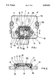
- FIG. 1 shows a plan view of the structure of an ignition control unit.
- FIG. 2 shows the ignition control unit in a section along the line A--A in FIG. 1.
- the ignition control unit contains a heat sink 15, a housing element 6 with plastic frame 7, a plug terminal jack 8 and cover 19, plus an electronic ignition circuit 1.
- All assemblies of the electronic ignition circuit 1, the control section 2, the power pack 3 and the RC combination including a capacitor 4 and a register 4', are jointly provided on the ceramic carrier element 5 used for electrical insulation of the electronic circuit unit 1 from the heat sink 15.
- a metal board 11 whose plug terminals 12, 13 are connected to the electronic circuit 1 via bonded wires 14 is integrated in the plastic housing element 6.
- the metal board 11 is therefore used for contacting the electronic circuit 1 and provides an external connection option for the ignition control unit via the plug terminal jack 8.
- the holes 10 in the flange-shaped part 9 of the plastic frame 7 are used for fastening the frame 7 to the heat sink 15.
- the holes 16 in the heat sink 15 are used for mounting the ignition control unit on a plate in the engine compartment of the vehicle.
- the electronic circuit 1 is pressed in a defined manner against the heat sink 15 during assembly using the pressure elements 20 integrated in the housing frame 7.
- the manufacturing and assembly method of the ignition control unit is described in the following.
- the circuit board for holding the electronic components of the ignition circuit comprises a ceramic carrier element 5, preferably of Al 2 O 3 provided with conducting paths and resistors in thick-film technology.
- the terminals of the other semiconductor elements are now provided with contacts using bonded wires on the conducting paths of the ceramic carrier element 5.
- the hybrid circuit 1 is now electrically operative, so that a necessary function alignment or check can be made on the already complete electronic circuit.
- a metal board 11 is enclosed with plastic by injection molding.
- the metal board 11 extends right into the plug terminal jack 8 and thus forms the contact terminals for an external plug connection of the ignition control unit.
- the hybrid circuit 1 is now placed on a heat sink 15 coated with adhesive and pressed in a defined manner against the heat sink 15, while the adhesive is setting, by means of the housing frame 7 fastened to the heat sink 15 with the aid of rivets 17.
- This pressing operation is effected using the deformable pressure elements 20 which are integrated in the housing frame and exert pressure on the heat spreader of the transistor chip. This measure generates the thin and pore-free adhesive layer required between the ceramic carrier 5 and the heat sink 15, which is necessary for good heat dissipation from the ceramic carrier to the heat sink.
- the housing terminals 12, 13 are connected by bonded wires 14 to the terminals on the electronic circuit 1, the circuit is then encapsulated using a soft sealing compound 21, and the housing frame 7 sealed with a cover 19.
- the ignition control unit is now ready for installation in the vehicle: mounting is on a sheet metal plate on the engine compartment with the aid of the holes 16 in the heat sink.
Abstract
The object of the patent application is an electronic control unit with triggering and power components, in particular an ignition control unit, whose electronic circuit comprises various assemblies in hybrid technology. To reduce the assembly expenditure and costs for manufacture, while at the same time reducing the volume, the invention provides for the assemblies of the electronic circuit to be integrated in a hybrid circuit and arranged on a single common carrier element. This carrier element is designed as an electrically non-conductive ceramic carrier of Al2 O3, by which the electronic circuit of the control unit is electrically insulated from a heat sink.
Description
This application is a continuation of application Ser. No. 07/433,986, Filed Nov. 9th, 1989, now abandoned.
The invention relates to an electronic control unit with triggering and power components, in particular an ignition control unit, whose circuit includes various subassemblies formed in hybrid technique.
Electronic ignition circuits, for example for automotive applications, consist of various parts or subassemblies, which are each assembled on a reseptive ceramic carrier as a hybrid circuit. A control unit, a switching element and an RC combination are usually required for this application.
The control unit, which serves to trigger and control the switching element, is built up on a ceramic substrate with printed conductor lines and resistors, by use of components in SMD- and chip form. The switching element represents the circuit breaker that switches the ignition coil current on and off in ignition control units. It comprises, for example, a power transistor chip soldered onto a metallic heat spreader used to improve the removal of dissipated power.
The RC combination contains a ceramic high-voltage capacitor and a power resistor. In ignition control units these components are either installed discretely in the plastic frame of the housing, or are mounted on a separate ceramic substrate which contains a printed power resistor and a high-voltage capacitor.
The dissipated power of the control unit is small compared with the power dissipation of the switching element. The dissipated power has to be removed to a heat sink.
For the electrical insulation of the control unit and of the switching element to heat sink, both of them are built up on a metallized ceramic substrate and mounted singly onto the heat sink. The electrical connection of the components to each other is made by Al-wire bonds.
An ignition control unit whose circuit components are deposited on an AlN ceramic carrier is known from German patent DE-PS 36 04 074.
However, the AlN ceramic carrier material is very expensive; in addition, the mechanically stabilizing heat sink is not present, so that the system is prone to breakage when fitted in the vehicle.
The object underlying the invention is to reduce the assembly expenditure and costs for manufacture of electronic control units, in particular of ignition control units, while at the same time reducing their volume. This is achieved in accordance with the invention by the components of the electronic circuit being integrated in a hybrid circuit and arranged on a single common carrier element.
Advantageous embodiments of the invention are given in the subclaims.
The electrical connection between the various assemblies and components of the electronic circuit has already been made within the common substrate, so that the additional wiring is reduced and assembly space between the individual circuit components is no longer needed. This leads to a high packing density, in conjunction with a lower space requirement.
Instead of testing the individual components, a joint function alignment or check of all circuit components can be made on the finished circuit.
Since the interconnections are dispensed with, and only a single unit must be mounted on the heat sink, inexpensive final assembly is also possible.
It is an advantage to use an inexpensive Al2 O3 ceramic carrier instead of an expensive and thick AlN ceramic carrier. Mounting this thin ceramic insulator on a mechanically stable aluminum heat sink presents no danger of damage to the control unit during final assembly.
The structure and the manufacture of an electronic control unit according to the invention is described in the following on the basis of an ignition control unit.
FIG. 1 shows a plan view of the structure of an ignition control unit.
FIG. 2 shows the ignition control unit in a section along the line A--A in FIG. 1.
According to FIG. 1 and 2, the ignition control unit contains a heat sink 15, a housing element 6 with plastic frame 7, a plug terminal jack 8 and cover 19, plus an electronic ignition circuit 1.
All assemblies of the electronic ignition circuit 1, the control section 2, the power pack 3 and the RC combination including a capacitor 4 and a register 4', are jointly provided on the ceramic carrier element 5 used for electrical insulation of the electronic circuit unit 1 from the heat sink 15.
A metal board 11 whose plug terminals 12, 13 are connected to the electronic circuit 1 via bonded wires 14 is integrated in the plastic housing element 6. The metal board 11 is therefore used for contacting the electronic circuit 1 and provides an external connection option for the ignition control unit via the plug terminal jack 8.
The holes 10 in the flange-shaped part 9 of the plastic frame 7 are used for fastening the frame 7 to the heat sink 15. The holes 16 in the heat sink 15 are used for mounting the ignition control unit on a plate in the engine compartment of the vehicle.
The electronic circuit 1 is pressed in a defined manner against the heat sink 15 during assembly using the pressure elements 20 integrated in the housing frame 7.
The manufacturing and assembly method of the ignition control unit is described in the following.
The circuit board for holding the electronic components of the ignition circuit comprises a ceramic carrier element 5, preferably of Al2 O3 provided with conducting paths and resistors in thick-film technology. Components in SMD and chip form, for example ICs and capacitors, and the transistor chip already soldered onto a heat spreader, are placed on the conducting paths provided with solder paste and connected both to the circuit board and to one another in a joint soldering operation.
The terminals of the other semiconductor elements are now provided with contacts using bonded wires on the conducting paths of the ceramic carrier element 5. The hybrid circuit 1 is now electrically operative, so that a necessary function alignment or check can be made on the already complete electronic circuit.
To form the housing element 6 with frame 7 and plug terminal jack 8, a metal board 11 is enclosed with plastic by injection molding. The metal board 11 extends right into the plug terminal jack 8 and thus forms the contact terminals for an external plug connection of the ignition control unit.
The hybrid circuit 1 is now placed on a heat sink 15 coated with adhesive and pressed in a defined manner against the heat sink 15, while the adhesive is setting, by means of the housing frame 7 fastened to the heat sink 15 with the aid of rivets 17. This pressing operation is effected using the deformable pressure elements 20 which are integrated in the housing frame and exert pressure on the heat spreader of the transistor chip. This measure generates the thin and pore-free adhesive layer required between the ceramic carrier 5 and the heat sink 15, which is necessary for good heat dissipation from the ceramic carrier to the heat sink.
In final assembly, the housing terminals 12, 13 are connected by bonded wires 14 to the terminals on the electronic circuit 1, the circuit is then encapsulated using a soft sealing compound 21, and the housing frame 7 sealed with a cover 19.
The ignition control unit is now ready for installation in the vehicle: mounting is on a sheet metal plate on the engine compartment with the aid of the holes 16 in the heat sink.
The integration of various assemblies on a single common carrier element can be used not only in ignition control units, but in all control units with triggering and power components that have various assemblies in hybrid technology.
Claims (3)
1. An electronic control unit comprising:
a housing including (a) a heat sink which forms a base of said housing and which is provided with mounting holes for mounting said unit on a support structure, (b) a closed frame member directly disposed on and fastened to a surface of said heat sink to define a cavity closed at one end with a surrounded portion of said surface of said heat sink, and (c) a separate cover on said frame member closing the other end of said cavity; and
a single hybrid integrated electronic circuit including switching and power components, arranged in a plurality of separate assemblies with differing power dissipations, disposed on a surface of a single common electrically non-conductive carrier consisting of Al2 O3, with said carrier being mounted directly on said surrounded portion of said surface of said heat sink within said cavity.
2. An electronic control unit according to claim 1 wherein said carrier is mounted on and fastened to said surface of said heat sink by an adhesive.
3. An electronic control unit according to claim 1 wherein said circuit is an electronic ignition circuit which contains, as said assemblies, a control section, a switching element and an RC combination, which are arranged on said surface of said common carrier, which surface is provided with conducting paths and resistors.
Applications Claiming Priority (2)
| Application Number | Priority Date | Filing Date | Title |
|---|---|---|---|
| DE3837975 | 1988-11-09 | ||
| DE3837975A DE3837975A1 (en) | 1988-11-09 | 1988-11-09 | ELECTRONIC CONTROL UNIT |
Related Parent Applications (1)
| Application Number | Title | Priority Date | Filing Date |
|---|---|---|---|
| US07433986 Continuation | 1989-11-09 |
Publications (1)
| Publication Number | Publication Date |
|---|---|
| US5159532A true US5159532A (en) | 1992-10-27 |
Family
ID=6366796
Family Applications (1)
| Application Number | Title | Priority Date | Filing Date |
|---|---|---|---|
| US07/707,198 Expired - Lifetime US5159532A (en) | 1988-11-09 | 1991-05-28 | Electronic control unit with multiple hybrid circuit assemblies integrated on a single common ceramic carrier |
Country Status (3)
| Country | Link |
|---|---|
| US (1) | US5159532A (en) |
| EP (1) | EP0368143A3 (en) |
| DE (1) | DE3837975A1 (en) |
Cited By (22)
| Publication number | Priority date | Publication date | Assignee | Title |
|---|---|---|---|---|
| US5299942A (en) * | 1993-02-18 | 1994-04-05 | Molex Incorporated | Input-output electrical connector |
| US5323532A (en) * | 1992-01-31 | 1994-06-28 | Motorola, Inc. | Method for providing novel hybrid circuit assembly carrier bracket |
| US5353194A (en) * | 1991-04-30 | 1994-10-04 | Sgs-Thomson Microelectronics S.R.L. | Modular power circuit assembly |
| US5365909A (en) * | 1992-06-15 | 1994-11-22 | Mitsubishi Denki Kabushiki Kaisha | Ignitor for an internal combustion engine |
| US5467758A (en) * | 1993-08-13 | 1995-11-21 | Hitachi, Ltd. | Electronic distributing type ignition device |
| US5558074A (en) * | 1994-07-28 | 1996-09-24 | Hitachi, Ltd. | Ignition device for internal-combustion engine |
| EP0751570A2 (en) * | 1995-06-26 | 1997-01-02 | Siemens Aktiengesellschaft | Combined electronic logic power module |
| US5622157A (en) * | 1995-06-09 | 1997-04-22 | Mitsubishi Denki Kabushiki Kaisha | Ignition apparatus for internal combustion engine and manufacturing method thereof |
| US5761039A (en) * | 1995-06-19 | 1998-06-02 | Hella Kg Hueck & Co. | Electrical load switch for a motor vehicle |
| EP0895446A2 (en) * | 1997-07-31 | 1999-02-03 | GKR Gesellschaft für Fahrzeugklimaregelung mbH | Controller for an electrical motor with a regulating circuit and a power semiconductor |
| US5917703A (en) * | 1998-04-17 | 1999-06-29 | Advanced Interconnections Corporation | Integrated circuit intercoupling component with heat sink |
| US6205031B1 (en) * | 1997-06-28 | 2001-03-20 | Robert Bosch Gmbh | Electronic control apparatus |
| US6259603B1 (en) * | 1997-11-13 | 2001-07-10 | Robert Bosch Gmbh | Electronic control unit |
| US6313977B1 (en) | 1998-10-16 | 2001-11-06 | Siemens Aktiengesellschaft | Circuit configuration for regulating the current fed to an electromechanical component in a motor vehicle |
| EP1023773B1 (en) * | 1997-10-17 | 2002-01-09 | Siemens Aktiengesellschaft | Circuit for regulating the current supplied to an electromechanical component in a motor vehicle |
| WO2003026008A2 (en) * | 2001-08-31 | 2003-03-27 | Siemens Aktiengesellschaft | Power electronics component |
| US6590774B2 (en) | 1993-12-27 | 2003-07-08 | Hitachi, Ltd. | Ignition apparatus for internal combustion engine with improved electrical insulation plate including beryllia |
| US6788546B1 (en) | 1999-03-19 | 2004-09-07 | Elmicron Ag | Multi-chip module |
| US20040264140A1 (en) * | 2001-08-31 | 2004-12-30 | Olaf Lucke | Power electronics component |
| US20080080147A1 (en) * | 2006-09-28 | 2008-04-03 | Tk Holdings Inc. | Electronic control module |
| US8167630B2 (en) | 1996-10-10 | 2012-05-01 | Fci Americas Technology Llc | High density connector and method of manufacture |
| US8618350B2 (en) | 2011-02-14 | 2013-12-31 | The Procter & Gamble Company | Absorbent articles with tear resistant film |
Families Citing this family (6)
| Publication number | Priority date | Publication date | Assignee | Title |
|---|---|---|---|---|
| DE4015311C2 (en) * | 1990-05-12 | 1993-12-16 | Vdo Schindling | Electrical circuitry |
| DE4131200C2 (en) * | 1991-09-19 | 1995-05-11 | Export Contor Ausenhandelsgese | Circuit arrangement |
| FR2685159B1 (en) * | 1991-12-17 | 1996-11-22 | Matra Sep Imagerie Inf | METHOD FOR MANUFACTURING ELECTRONIC CIRCUITS WITH BARE MICRO-COMPONENTS AND ENCAPSULATED CIRCUIT REALIZABLE BY THIS PROCESS. |
| DE19807718C2 (en) * | 1998-02-24 | 2000-12-07 | Lear Automotive Electronics Gm | Electronics assembly |
| DE19908108A1 (en) * | 1999-02-25 | 2000-08-31 | Diehl Stiftung & Co | Energy generator for shell ignition circuit has wind wheel generator with permanent magnetic rotor and stator inductance in form of at least one SMD inductance |
| DE10129788B4 (en) * | 2001-06-20 | 2005-11-10 | Siemens Ag | Plastic frame for mounting an electronic power control unit |
Citations (19)
| Publication number | Priority date | Publication date | Assignee | Title |
|---|---|---|---|---|
| US3710193A (en) * | 1971-03-04 | 1973-01-09 | Lambda Electronics Corp | Hybrid regulated power supply having individual heat sinks for heat generative and heat sensitive components |
| DE2150695A1 (en) * | 1971-10-12 | 1973-04-19 | Bosch Gmbh Robert | Semiconductive elements - formed on metallic support provided with intermediate insulating layer |
| GB1476886A (en) * | 1974-04-22 | 1977-06-16 | Trw Inc | Ceramic printed circuit board structure |
| US4047242A (en) * | 1975-07-05 | 1977-09-06 | Robert Bosch G.M.B.H. | Compact electronic control and power unit structure |
| DE7822999U1 (en) * | 1978-08-01 | 1980-01-17 | Licentia Patent-Verwaltungs-Gmbh, 6000 Frankfurt | SHIFT SWITCHING MODULE |
| US4310792A (en) * | 1978-06-30 | 1982-01-12 | Mitsubishi Denki Kabushiki Kaisha | Semiconductor voltage regulator |
| DE8317699U1 (en) * | 1983-06-18 | 1984-11-29 | Robert Bosch Gmbh, 7000 Stuttgart | Switching device, in particular ignition switching device for ignition systems of internal combustion engines |
| US4557225A (en) * | 1984-01-18 | 1985-12-10 | Mikuni Kogyo Kabushiki Kaisha | Combined housing and heat sink for electronic engine control system components |
| US4605986A (en) * | 1984-03-13 | 1986-08-12 | Robert Bosch Gmbh | Cooled electrical circuit component, particularly switching-type semiconductor |
| US4646203A (en) * | 1985-02-06 | 1987-02-24 | Lutron Electronics Co., Inc. | Mounting structure for semiconductor devices |
| DE3604074A1 (en) * | 1986-02-08 | 1987-08-13 | Bosch Gmbh Robert | IGNITION SWITCH |
| DE8623251U1 (en) * | 1986-08-29 | 1987-12-23 | Robert Bosch Gmbh, 7000 Stuttgart, De | |
| DE8715073U1 (en) * | 1987-11-12 | 1988-02-25 | Siemens Ag, 1000 Berlin Und 8000 Muenchen, De | |
| US4731693A (en) * | 1986-09-29 | 1988-03-15 | Tektronix, Inc. | Connection apparatus for integrated circuit |
| US4763224A (en) * | 1985-04-20 | 1988-08-09 | Robert Bosch Gmbh | Housing for receiving electric control devices, in particular for motor vehicles |
| US4766520A (en) * | 1986-12-05 | 1988-08-23 | Capsonic Group, Inc. | Injection molded circuit housing |
| US4845590A (en) * | 1987-11-02 | 1989-07-04 | Chrysler Motors Corporation | Heat sink for electrical components |
| US4893590A (en) * | 1987-09-30 | 1990-01-16 | Hitachi, Ltd. | Automotive liquid-cooled electronic control apparatus |
| US4899256A (en) * | 1988-06-01 | 1990-02-06 | Chrysler Motors Corporation | Power module |
Family Cites Families (3)
| Publication number | Priority date | Publication date | Assignee | Title |
|---|---|---|---|---|
| JPS5769768A (en) * | 1980-10-20 | 1982-04-28 | Fujitsu Ltd | Equipping structure of electronic circuit unit containing high electric power parts |
| US4471314A (en) * | 1981-06-15 | 1984-09-11 | Lindberg Charles R | Hybrid pulse width modulated audio amplifier |
| JPS60122281A (en) * | 1983-12-06 | 1985-06-29 | Nippon Denso Co Ltd | Igniter of internal-combustion engine |
-
1988
- 1988-11-09 DE DE3837975A patent/DE3837975A1/en not_active Ceased
-
1989
- 1989-11-02 EP EP19890120280 patent/EP0368143A3/en not_active Withdrawn
-
1991
- 1991-05-28 US US07/707,198 patent/US5159532A/en not_active Expired - Lifetime
Patent Citations (19)
| Publication number | Priority date | Publication date | Assignee | Title |
|---|---|---|---|---|
| US3710193A (en) * | 1971-03-04 | 1973-01-09 | Lambda Electronics Corp | Hybrid regulated power supply having individual heat sinks for heat generative and heat sensitive components |
| DE2150695A1 (en) * | 1971-10-12 | 1973-04-19 | Bosch Gmbh Robert | Semiconductive elements - formed on metallic support provided with intermediate insulating layer |
| GB1476886A (en) * | 1974-04-22 | 1977-06-16 | Trw Inc | Ceramic printed circuit board structure |
| US4047242A (en) * | 1975-07-05 | 1977-09-06 | Robert Bosch G.M.B.H. | Compact electronic control and power unit structure |
| US4310792A (en) * | 1978-06-30 | 1982-01-12 | Mitsubishi Denki Kabushiki Kaisha | Semiconductor voltage regulator |
| DE7822999U1 (en) * | 1978-08-01 | 1980-01-17 | Licentia Patent-Verwaltungs-Gmbh, 6000 Frankfurt | SHIFT SWITCHING MODULE |
| DE8317699U1 (en) * | 1983-06-18 | 1984-11-29 | Robert Bosch Gmbh, 7000 Stuttgart | Switching device, in particular ignition switching device for ignition systems of internal combustion engines |
| US4557225A (en) * | 1984-01-18 | 1985-12-10 | Mikuni Kogyo Kabushiki Kaisha | Combined housing and heat sink for electronic engine control system components |
| US4605986A (en) * | 1984-03-13 | 1986-08-12 | Robert Bosch Gmbh | Cooled electrical circuit component, particularly switching-type semiconductor |
| US4646203A (en) * | 1985-02-06 | 1987-02-24 | Lutron Electronics Co., Inc. | Mounting structure for semiconductor devices |
| US4763224A (en) * | 1985-04-20 | 1988-08-09 | Robert Bosch Gmbh | Housing for receiving electric control devices, in particular for motor vehicles |
| DE3604074A1 (en) * | 1986-02-08 | 1987-08-13 | Bosch Gmbh Robert | IGNITION SWITCH |
| DE8623251U1 (en) * | 1986-08-29 | 1987-12-23 | Robert Bosch Gmbh, 7000 Stuttgart, De | |
| US4731693A (en) * | 1986-09-29 | 1988-03-15 | Tektronix, Inc. | Connection apparatus for integrated circuit |
| US4766520A (en) * | 1986-12-05 | 1988-08-23 | Capsonic Group, Inc. | Injection molded circuit housing |
| US4893590A (en) * | 1987-09-30 | 1990-01-16 | Hitachi, Ltd. | Automotive liquid-cooled electronic control apparatus |
| US4845590A (en) * | 1987-11-02 | 1989-07-04 | Chrysler Motors Corporation | Heat sink for electrical components |
| DE8715073U1 (en) * | 1987-11-12 | 1988-02-25 | Siemens Ag, 1000 Berlin Und 8000 Muenchen, De | |
| US4899256A (en) * | 1988-06-01 | 1990-02-06 | Chrysler Motors Corporation | Power module |
Non-Patent Citations (4)
| Title |
|---|
| DE 2: Bosch Technische Unterrichtung: Batteriez ndung S. 15, 13,18,22. * |
| DE 2: Graves, P. W. Dickschichttechnik Werkstoffe und Zuverl ssigkeit, Elektrisches Nachrichtenusen, Bd. 57, Nr. 2, 1982, S. 127 130. * |
| DE-2: Bosch Technische Unterrichtung: "Batteriezundung" S. 15, 13,18,22. |
| DE-2: Graves, P. W. Dickschichttechnik-Werkstoffe und Zuverlassigkeit, Elektrisches Nachrichtenusen, Bd. 57, Nr. 2, 1982, S. 127-130. |
Cited By (30)
| Publication number | Priority date | Publication date | Assignee | Title |
|---|---|---|---|---|
| US5353194A (en) * | 1991-04-30 | 1994-10-04 | Sgs-Thomson Microelectronics S.R.L. | Modular power circuit assembly |
| US5323532A (en) * | 1992-01-31 | 1994-06-28 | Motorola, Inc. | Method for providing novel hybrid circuit assembly carrier bracket |
| US5365909A (en) * | 1992-06-15 | 1994-11-22 | Mitsubishi Denki Kabushiki Kaisha | Ignitor for an internal combustion engine |
| US5299942A (en) * | 1993-02-18 | 1994-04-05 | Molex Incorporated | Input-output electrical connector |
| US5467758A (en) * | 1993-08-13 | 1995-11-21 | Hitachi, Ltd. | Electronic distributing type ignition device |
| US6590774B2 (en) | 1993-12-27 | 2003-07-08 | Hitachi, Ltd. | Ignition apparatus for internal combustion engine with improved electrical insulation plate including beryllia |
| US5558074A (en) * | 1994-07-28 | 1996-09-24 | Hitachi, Ltd. | Ignition device for internal-combustion engine |
| US5622157A (en) * | 1995-06-09 | 1997-04-22 | Mitsubishi Denki Kabushiki Kaisha | Ignition apparatus for internal combustion engine and manufacturing method thereof |
| US5761039A (en) * | 1995-06-19 | 1998-06-02 | Hella Kg Hueck & Co. | Electrical load switch for a motor vehicle |
| EP0751570A3 (en) * | 1995-06-26 | 1999-04-28 | Siemens Aktiengesellschaft | Combined electronic logic power module |
| EP0751570A2 (en) * | 1995-06-26 | 1997-01-02 | Siemens Aktiengesellschaft | Combined electronic logic power module |
| US8167630B2 (en) | 1996-10-10 | 2012-05-01 | Fci Americas Technology Llc | High density connector and method of manufacture |
| US6205031B1 (en) * | 1997-06-28 | 2001-03-20 | Robert Bosch Gmbh | Electronic control apparatus |
| EP0895446A2 (en) * | 1997-07-31 | 1999-02-03 | GKR Gesellschaft für Fahrzeugklimaregelung mbH | Controller for an electrical motor with a regulating circuit and a power semiconductor |
| EP0895446A3 (en) * | 1997-07-31 | 2000-08-30 | GKR Gesellschaft für Fahrzeugklimaregelung mbH | Controller for an electrical motor with a regulating circuit and a power semiconductor |
| EP1023773B1 (en) * | 1997-10-17 | 2002-01-09 | Siemens Aktiengesellschaft | Circuit for regulating the current supplied to an electromechanical component in a motor vehicle |
| US6259603B1 (en) * | 1997-11-13 | 2001-07-10 | Robert Bosch Gmbh | Electronic control unit |
| US5917703A (en) * | 1998-04-17 | 1999-06-29 | Advanced Interconnections Corporation | Integrated circuit intercoupling component with heat sink |
| US6313977B1 (en) | 1998-10-16 | 2001-11-06 | Siemens Aktiengesellschaft | Circuit configuration for regulating the current fed to an electromechanical component in a motor vehicle |
| US6788546B1 (en) | 1999-03-19 | 2004-09-07 | Elmicron Ag | Multi-chip module |
| WO2003026008A2 (en) * | 2001-08-31 | 2003-03-27 | Siemens Aktiengesellschaft | Power electronics component |
| US20040206534A1 (en) * | 2001-08-31 | 2004-10-21 | Olaf Lucke | Power electronics component |
| US20040264140A1 (en) * | 2001-08-31 | 2004-12-30 | Olaf Lucke | Power electronics component |
| US6846987B2 (en) | 2001-08-31 | 2005-01-25 | Siemens Aktiengesellschaft | Power electronics component |
| US7236367B2 (en) | 2001-08-31 | 2007-06-26 | Siemens Aktiengesellschaft | Power electronics component |
| WO2003026008A3 (en) * | 2001-08-31 | 2003-08-21 | Siemens Ag | Power electronics component |
| US20080080147A1 (en) * | 2006-09-28 | 2008-04-03 | Tk Holdings Inc. | Electronic control module |
| US8618350B2 (en) | 2011-02-14 | 2013-12-31 | The Procter & Gamble Company | Absorbent articles with tear resistant film |
| US9000253B2 (en) | 2011-02-14 | 2015-04-07 | The Procter & Gamble Company | Absorbent article with tear resistant film |
| US9962296B2 (en) | 2011-02-14 | 2018-05-08 | The Procter & Gamble Company | Absorbent article with tear resistant film |
Also Published As
| Publication number | Publication date |
|---|---|
| EP0368143A2 (en) | 1990-05-16 |
| EP0368143A3 (en) | 1991-03-27 |
| DE3837975A1 (en) | 1990-05-10 |
Similar Documents
| Publication | Publication Date | Title |
|---|---|---|
| US5159532A (en) | Electronic control unit with multiple hybrid circuit assemblies integrated on a single common ceramic carrier | |
| JP4264375B2 (en) | Power semiconductor module | |
| US5536972A (en) | Power module | |
| US4819041A (en) | Surface mounted integrated circuit chip package and method for making same | |
| EP1065916B1 (en) | Resin sealed electronic device | |
| JPH1174433A (en) | Semiconductor device | |
| JPH07508858A (en) | Assembly unit for multilayer hybrids with power elements | |
| JP2000509560A (en) | Multi-chip module | |
| US4949220A (en) | Hybrid IC with heat sink | |
| US5699233A (en) | Control unit housing with interconnecting conductor paths | |
| US5761039A (en) | Electrical load switch for a motor vehicle | |
| JP2001507522A (en) | Electronic control unit | |
| JP2848068B2 (en) | Semiconductor device | |
| US3346774A (en) | Electrical component substrate with cavities for anchoring lead wires therein | |
| JP3842010B2 (en) | Electronic equipment having multiple substrates | |
| US5422515A (en) | Semiconductor module including wiring structures each having different current capacity | |
| JPH09321216A (en) | Power semiconductor device | |
| JPH09213878A (en) | Semiconductor device | |
| JPS6227544B2 (en) | ||
| US4520384A (en) | Power semiconductor component for cooling by boiling or liquids | |
| JPH07122680A (en) | Hybrid integrated circuit device | |
| JP3890850B2 (en) | Electronic circuit equipment | |
| JPH0451486Y2 (en) | ||
| JPH09289283A (en) | Semiconductor device | |
| JP2999930B2 (en) | Hybrid integrated circuit device and method of manufacturing the same |
Legal Events
| Date | Code | Title | Description |
|---|---|---|---|
| STCF | Information on status: patent grant |
Free format text: PATENTED CASE |
|
| FEPP | Fee payment procedure |
Free format text: PAYOR NUMBER ASSIGNED (ORIGINAL EVENT CODE: ASPN); ENTITY STATUS OF PATENT OWNER: LARGE ENTITY |
|
| FPAY | Fee payment |
Year of fee payment: 4 |
|
| FEPP | Fee payment procedure |
Free format text: PAYER NUMBER DE-ASSIGNED (ORIGINAL EVENT CODE: RMPN); ENTITY STATUS OF PATENT OWNER: LARGE ENTITY |
|
| FPAY | Fee payment |
Year of fee payment: 8 |
|
| FEPP | Fee payment procedure |
Free format text: PAYOR NUMBER ASSIGNED (ORIGINAL EVENT CODE: ASPN); ENTITY STATUS OF PATENT OWNER: LARGE ENTITY |
|
| FPAY | Fee payment |
Year of fee payment: 12 |