US5165728A - Nipple intended to cooperate with multiple coupling components - Google Patents
Nipple intended to cooperate with multiple coupling components Download PDFInfo
- Publication number
- US5165728A US5165728A US07/643,421 US64342191A US5165728A US 5165728 A US5165728 A US 5165728A US 64342191 A US64342191 A US 64342191A US 5165728 A US5165728 A US 5165728A
- Authority
- US
- United States
- Prior art keywords
- longitudinally extending
- cylindrical member
- hollow cylindrical
- extending hollow
- nipple
- Prior art date
- Legal status (The legal status is an assumption and is not a legal conclusion. Google has not performed a legal analysis and makes no representation as to the accuracy of the status listed.)
- Expired - Lifetime
Links
Images


Classifications
-
- F—MECHANICAL ENGINEERING; LIGHTING; HEATING; WEAPONS; BLASTING
- F16—ENGINEERING ELEMENTS AND UNITS; GENERAL MEASURES FOR PRODUCING AND MAINTAINING EFFECTIVE FUNCTIONING OF MACHINES OR INSTALLATIONS; THERMAL INSULATION IN GENERAL
- F16L—PIPES; JOINTS OR FITTINGS FOR PIPES; SUPPORTS FOR PIPES, CABLES OR PROTECTIVE TUBING; MEANS FOR THERMAL INSULATION IN GENERAL
- F16L25/00—Constructive types of pipe joints not provided for in groups F16L13/00 - F16L23/00 ; Details of pipe joints not otherwise provided for, e.g. electrically conducting or insulating means
- F16L25/009—Combination of a quick-acting type coupling and a conventional one
-
- A—HUMAN NECESSITIES
- A61—MEDICAL OR VETERINARY SCIENCE; HYGIENE
- A61M—DEVICES FOR INTRODUCING MEDIA INTO, OR ONTO, THE BODY; DEVICES FOR TRANSDUCING BODY MEDIA OR FOR TAKING MEDIA FROM THE BODY; DEVICES FOR PRODUCING OR ENDING SLEEP OR STUPOR
- A61M39/00—Tubes, tube connectors, tube couplings, valves, access sites or the like, specially adapted for medical use
- A61M39/10—Tube connectors; Tube couplings
- A61M2039/1033—Swivel nut connectors, e.g. threaded connectors, bayonet-connectors
-
- A—HUMAN NECESSITIES
- A61—MEDICAL OR VETERINARY SCIENCE; HYGIENE
- A61M—DEVICES FOR INTRODUCING MEDIA INTO, OR ONTO, THE BODY; DEVICES FOR TRANSDUCING BODY MEDIA OR FOR TAKING MEDIA FROM THE BODY; DEVICES FOR PRODUCING OR ENDING SLEEP OR STUPOR
- A61M39/00—Tubes, tube connectors, tube couplings, valves, access sites or the like, specially adapted for medical use
- A61M39/10—Tube connectors; Tube couplings
- A61M2039/1083—Tube connectors; Tube couplings having a plurality of female connectors, e.g. Luer connectors
-
- A—HUMAN NECESSITIES
- A61—MEDICAL OR VETERINARY SCIENCE; HYGIENE
- A61M—DEVICES FOR INTRODUCING MEDIA INTO, OR ONTO, THE BODY; DEVICES FOR TRANSDUCING BODY MEDIA OR FOR TAKING MEDIA FROM THE BODY; DEVICES FOR PRODUCING OR ENDING SLEEP OR STUPOR
- A61M39/00—Tubes, tube connectors, tube couplings, valves, access sites or the like, specially adapted for medical use
- A61M39/10—Tube connectors; Tube couplings
- A61M2039/1088—Tube connectors; Tube couplings having a plurality of male connectors, e.g. Luer connectors
Definitions
- the present invention relates to a nipple, and in particular, a nipple which is intended to form part of a so-called Hansen coupling. More particularly, the present invention relates to nipples intended for use with Hansen couplings in which one coupling component comprises the nipple which includes at least one recess on its outer peripheral surface while the other coupling component has a sleeve-like portion, which is capable of being telescopically pushed over the nipple, and which includes a locking means, such as balls, which are engaged in the recess on the outer surface of the nipple.
- the present invention relates to nipples which are intended to form part of a dialyzer or similar diffusion and/or filtration device. Still more particularly, the present invention relates to such nipples which are intended for use in such apparatus so as to render it possible to couple same to different tube systems, which can include coupling components intended either for throw-away use or which are intended for multiple utilization. Alternatively, the present invention is also directed to such nipples which can form part of a tube coupling for the coupling together of two tubular components.
- Hansen couplings there are a number of different examples of Hansen couplings, such as those shown in U.S. Pat. Nos. 2,518,542; 3,351,362 and 4,198,080. As is evident from the sheer number of these patents, this type of coupling has been in use for a rather long period of time.
- These Hansen-type couplings consist, on the one side, of a nipple, and on the other side of a sleeve-like portion which is capable of being telescopically pushed over the nipple.
- the sleeve-like portion of the coupling exists in various forms including both simple and somewhat more complicated variants. They each have the common disadvantage, however, that they are too expensive to be used simply for throw-away use.
- the other coupling component i.e., the nipples themselves, may, of example, form part of a dialyzer, and thus be coupled normally by means of conventional Hansen couplings to tubes originating from a conventional dialysis monitor. If it is desired to use this same housing provided with such nipples in connection with hemofiltration, for example, the nipples must then be coupled to a tube set which is intended for throw-away use. Because of the concomitant high cost, such an arrangement cannot comprise conventional Hansen couplings, but must instead make use of simpler couplings, such as simple threaded plastic components and the like.
- a nipple which can be used for coupling to a plurality of secondary coupling components
- the nipple comprising a longitudinally extending hollow cylindrical member having an outer surface, an inner surface, an inner end, and an outer end, with the outer surface of the longitudinally extending hollow cylindrical member including an outer recess adapted for engagement with a Hansen-type secondary coupling component, including locking means for engaging the outer recess, and the nipple further including thread means located between the outer recess and the outer end of the longitudinally extending hollow cylindrical member, the thread means being adapted for engagement with a threaded secondary coupling component including corresponding threads thereon.
- the nipple in accordance with this invention is thus adapted so that it can form part of a so-called Hansen coupling, and thus includes a nipple with one or more recesses on its outer peripheral surface so that it can couple with a secondary coupling component having a sleeve-like part capable of being telescopically pushed over the nipple and which is provided on its inside with locking means such as balls which can engage in the recess or recesses of the nipple, and which is further characterized by a thread arranged either on the inside or the outside of the nipple and situated between the outer end of the nipple and the recess or recesses, and which is suitable for coupling together with other coupling components provided with a matching thread therefor.
- the recess on the outer surface of the nipple preferably constitutes a circular groove around the entire periphery of the nipple, the groove being separated from the outer end of the nipple by a raised cylindrical portion.
- This groove can be replaced by one or more recesses of different shapes and sizes.
- the thread means are located on the outer surface of the longitudinally extending hollow cylindrical member.
- the thread means are located on the inner surface of the longitudinally extending hollow cylindrical member.
- that member also includes a raised cylindrical portion located between the annular groove and the outer end of the longitudinally extending hollow cylindrical member.
- the raised cylindrical portion is adapted to serve as a sealing surface with respect to at least one of the plurality of secondary coupling components.
- the nipple includes a chamfered surface located between the raised cylindrical portion and the outer end of the longitudinally extending hollow cylindrical member, the chamfered surface being adapted to act as a seal with respect to at least one of the plurality of secondary coupling components.
- either the raised cylindrical portion itself can be adapted to serve as a sealing surface upon coupling, or it can be finished off on the outside by an inwardly chamfered sealing surface which is adapted to either seal against the other coupling component or against a packing or other seal provided therein.
- the raised cylindrical portion has a first diameter
- the outer end of the longitudinally extending hollow cylindrical member includes an end cylindrical portion having a second diameter, with the second diameter being less than the first diameter
- the thread means are preferably dimensioned such that the threads are not engageable with the locking means of the Hansen-type secondary coupling component.
- the nipple is preferably designed such that the locking means in the Hansen-type secondary coupling component to which it is to be coupled cannot fall down in locking position into the thread, but can only do so with the recess or recesses specifically adapted therefor.
- 4,198,080 can be obtained with its ridges extending axially to the nipple, i.e., so that a reduced build-up of material in the otherwise thickened portion of the nipple can be utilized without any risk of an incorrect locking position being created.
- the thread means has a predetermined depth so as to provide an internal thread diameter for the thread means, and the second diameter of the end cylindrical portion is less than that internal thread diameter.
- nipple includes the aforementioned end cylindrical portion which is narrower than the raised cylindrical portion, and these two portions are further separated by a chamfered surface whose original height is preferably slightly higher than the depth of the threads.
- the thread means comprise a plurality of axially extending bead components which are adapted to interact with an internal valve in the Hansen-type secondary coupling component.
- this plurality of bead components comprise three such bead components evenly distributed about the inner surface of the longitudinally extending hollow cylindrical member.
- the threads are thus arranged in a number of axially extending ridges or beads which are inwardly directed and which, in connection with a standard Hansen coupling, are intended to open an inner valve in that other coupling component.
- An acceptable thread can be achieved if these ridges or grooves are three in number and are evenly distributed about the periphery of the inner, otherwise cylindrical surface of the nipple.
- the end cylindrical portion having a reduced diameter is adapted to sealingly cooperate with a sealing bead directed inwardly from the second coupling component.
- the nipple can itself be provided with a sealing bead, which is adapted to seal against a smooth cylindrical sealing surface facing inwardly from the other coupling component.
- the seal can be further improved if the threads are adapted to extend in towards the recess or recesses but without reaching same.
- these thread means are separated from the outer recess on the outer surface of the longitudinally extending hollow cylindrical member.
- apparatus for diffusion or filtration including at least one nipple, the nipple being adapted for use in coupling the apparatus to a plurality of secondary coupling components, and the nipple including a longitudinally extending hollow cylindrical member having an inner surface, an outer surface, an inner end and an outer end, and the outer surface of the longitudinally extending hollow cylindrical member including an outer recess adapted for engagement with a Hansen-type secondary coupling component including locking means for engaging said outer recess, said nipple including thread means located between the recess and the outer end of the longitudinally extending hollow cylindrical member and being adapted for engagement with a threaded secondary coupling component including corresponding threads thereon.
- the present invention relates to application of such a nipple in a manner such that the nipple can be used to couple a dialyzer or similar diffusion and/or filtration device to different tube systems which can include coupling components intended either for throw-away use or of the type which are intended for multiple use.
- FIG. 1 is a side, elevational view of a dialyzer or other such diffusion and/or filtration device modified with two nipples according to the present invention
- FIG. 1a is a side, elevational, partial, enlarged view of one of the nipples shown in FIG. 1;
- FIG. 2A is a side, elevational, sectional view of a Hansen-type coupling component for coupling to a nipple in accordance with the present invention
- FIG. 2B is a side, elevational, sectional view of another secondary coupling component for coupling to a nipple in accordance with the present invention
- FIG. 2C is a side, elevational, sectional view of another secondary coupling component for coupling to a nipple in accordance with the present invention.
- FIG. 2D is a side, elevational, sectional view of another secondary coupling component for coupling to a nipple in accordance with the present invention.
- FIG. 3A is a side, elevational, partially sectional view of the coupling component of FIG. 2A coupled to a nipple in accordance with the present invention
- FIG. 3B is a side, elevational, partially sectional view of the coupling component of FIG. 2B coupled to a nipple in accordance with the present invention
- FIG. 3C is a side, elevational, partially sectional view of the coupling component of FIG. 2C coupled to a nipple in accordance with the present invention
- FIG. 3D is a side, elevational, sectional view of the coupling component of FIG. 2D coupled to a nipple in accordance with the present invention
- FIG. 3E is an enlarged view of a portion of FIG. 3D;
- FIG. 4 is a side, elevational view of a dialyzer or other diffusion and/or filtration device modified with two nipples in accordance with another embodiment of the present invention including an internal thread;
- FIG. 4A is a side, elevational, partial, enlarged view of one of the nipples shown in FIG. 4;
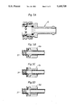
- FIG. 5A is a side, elevational, sectional view of a Hansen-type coupling component for coupling to a nipple in accordance with the present invention
- FIG. 5B is a side, elevational, partial, sectional view of another secondary coupling component for coupling to a nipple in accordance with the present invention.
- FIG. 5C is a side, elevational, partially sectional view of another secondary coupling component for coupling to a nipple in accordance with the present invention.
- FIG. 5D is a side, elevational, partially sectional view of another coupling component for coupling to a nipple in accordance with the present invention.
- FIG. 6A is a side, elevational, partially sectional view of the coupling component of FIG. 5A coupled to a nipple in accordance with the present invention
- FIG. 6B is a side, elevational, partially sectional view of the coupling component of FIG. 5B coupled to a nipple in accordance with the present invention
- FIG. 6C is a side, elevational, partially sectional view of the coupling component of FIG. 5C coupled to a nipple in accordance with the present invention
- FIG. 6D is a side, elevational, partially sectional view of the coupling component of FIG. 5D coupled to a nipple in accordance with the present invention.
- FIG. 7 is an end elevational view of another embodiment of a nipple in accordance with the present invention.
- FIGS. 1 and 4 in which like reference numerals refer to like portions thereof, it is first noted that the specific designs shown in FIGS. 1 and 4 will be referred to, for purposes of clarity, simply as dialyzers.
- FIG. 1 shows a dialyzer 1 consisting of a casing 2 having two end closure parts 3, and with an inlet 4 and an outlet 5 for the dialyzed fluid. If the design shown in FIG. 1 is used solely for dialysis, dialysis fluid is supplied and withdrawn through two nipples 6.
- Nipple 6 is shown on a larger scale in FIG. 1a.
- Nipple 6 is provided about its periphery with a recess 7 having chamfered walls 8 and 9.
- the outer end of the nipple is designated by reference numeral 10.
- a raised cylindrical portion 11 As is customary on nipples which are used for conventional Hansen couplings. This is finished off towards the outer end 10 thereof by a chamfered surface 12, which is separated from the outer end 10 by a lowered or reduced diameter cylindrical portion 13.
- the nipple 6 is provided with a thread 14 on the raised cylindrical portion 11.
- FIG. 2A there is shown a coupling component 15, which is standard for a conventional Hansen coupling, and is adapted to be coupled to the nipple 6 shown in FIG. 1A.
- the coupling component 15 is provided with locking means 16 acting inwardly, in this case being balls which are intended to engage in the groove 7 in the nipple 6 upon coupling.
- the balls 16 are controlled in a conventional manner, by means of guide ring 17 arranged between a spring 18 and a lock ring 19.
- the coupling component shown also comprises a packing 20.
- FIGS. 2B, 2C and 2D thee are shown three further coupling components 15b, 15c and 15d, respectively, each of which is provided with an internal thread 14' matching thread 14.
- the coupling components according to FIGS. 2B and 2C are also provided with a packing, 20b and 20c, respectively.
- each of the coupling components in accordance with FIGS. 2A through 2D fit the nipple 6, and can be sealingly coupled thereto.
- the specific seal in accordance with the design according to FIG. 3D is brought about by means of a sealing bead 23, which is specifically shown in the enlarged circular section thereof shown in this Figure.
- FIGS. 4 through 6D correspond in principle to those according to FIGS. 1 through 3D. Corresponding parts, therefore, have been given the same reference numerals. The difference in these cases lie in the fact that the external thread 14 in FIG. 1A, for example, has been replaced by an internal thread, which is designated by reference numeral 21 in FIG. 4A. In the same manner, the internal thread 14' in FIGS. 2B though 2D is replaced by an external thread 21' in FIGS. 5B through 5D.
- the internal thread 21 may be continuous, as shown schematically in FIG. 4A. Preferably, however, it is broken up, and presented by a number of axially extending ridges 22, as shown in FIG. 7.
- each of the coupling components according to FIGS. 5A through 5D fit he nipple 6, as shown in FIG. 4A. A further detailed description of FIGS. 4 through 7 is therefore not required.
- the present invention is not limited solely to the examples of embodiments described above, but can be varied within the framework of the following claims.
- the groove 7 in the nipple 6 may be given many different designs, either as one recess or as a number of recesses.
Abstract
Description
Claims (25)
Applications Claiming Priority (2)
| Application Number | Priority Date | Filing Date | Title |
|---|---|---|---|
| SE9000541 | 1990-02-15 | ||
| SE9000541A SE466813B (en) | 1990-02-15 | 1990-02-15 | APPLICATION OF A NIPLE, INTENDED TO PREPARE A PART OF A S HANSEN COUPLING |
Publications (1)
| Publication Number | Publication Date |
|---|---|
| US5165728A true US5165728A (en) | 1992-11-24 |
Family
ID=20378569
Family Applications (1)
| Application Number | Title | Priority Date | Filing Date |
|---|---|---|---|
| US07/643,421 Expired - Lifetime US5165728A (en) | 1990-02-15 | 1991-01-22 | Nipple intended to cooperate with multiple coupling components |
Country Status (7)
| Country | Link |
|---|---|
| US (1) | US5165728A (en) |
| EP (1) | EP0442310B1 (en) |
| JP (1) | JP3452589B2 (en) |
| DE (1) | DE69100283T2 (en) |
| DK (1) | DK0442310T3 (en) |
| ES (1) | ES2043395T3 (en) |
| SE (1) | SE466813B (en) |
Cited By (17)
| Publication number | Priority date | Publication date | Assignee | Title |
|---|---|---|---|---|
| US5335943A (en) * | 1993-04-20 | 1994-08-09 | Duane Duryea | Automobile engine hose system with plurality of adaptor members |
| US5613484A (en) * | 1996-02-07 | 1997-03-25 | Golden Key Futura, Inc. | Archery bow and connector-stabilizer assembly and improved connector-stabilizer sub-assembly for the same |
| US5845943A (en) * | 1996-12-02 | 1998-12-08 | Colder Products Company | Hybrid insert for fluid couplings |
| US5896889A (en) * | 1997-10-24 | 1999-04-27 | Menard; Orville R. | Quick-set hydraulic coupler |
| US6824415B2 (en) * | 2001-11-01 | 2004-11-30 | Andrew Corporation | Coaxial connector with spring loaded coupling mechanism |
| US20070075003A1 (en) * | 2003-11-10 | 2007-04-05 | Helmut Schmidt | Connector for dialysis port |
| US20080077176A1 (en) * | 2006-09-21 | 2008-03-27 | Tyco Healthcare Group Lp | Safety connector assembly |
| US20080271798A1 (en) * | 2007-05-04 | 2008-11-06 | Burdsall Thomas A | Gas appliance |
| US20090240178A1 (en) * | 2008-03-20 | 2009-09-24 | Tyco Healthcare Group Lp | Safety connector assembly |
| US20090276989A1 (en) * | 2008-05-06 | 2009-11-12 | Halia Accessories Inc. | Strand Locking Mechanism Assembly |
| US7762279B2 (en) | 2005-11-05 | 2010-07-27 | Snap-Tite Technologies, Inc. | Threaded coupling with flow shutoff |
| US20100270225A1 (en) * | 2009-04-23 | 2010-10-28 | Fresenius Medical Care Deutschland Gmbh | Retaining means for retaining an external functional means on a treatment apparatus, external functional means, and treatment apparatus |
| US20110101674A1 (en) * | 2008-07-08 | 2011-05-05 | Sit La Precisa S.P.A. Con Socio Unico | System for the leaktight connection of valve units to respective pipes, in particular for use with combustible gases |
| US7987754B2 (en) | 2007-07-31 | 2011-08-02 | Newell Window Furnishings, Inc. | Window covering sizing method and apparatus |
| US20130014757A1 (en) * | 2011-07-15 | 2013-01-17 | Mcphearson Jack C | Fast Connect Device for Oxygen Humidity Bottles and other medical containers |
| US9649436B2 (en) | 2011-09-21 | 2017-05-16 | Bayer Healthcare Llc | Assembly method for a fluid pump device for a continuous multi-fluid delivery system |
| US10507319B2 (en) | 2015-01-09 | 2019-12-17 | Bayer Healthcare Llc | Multiple fluid delivery system with multi-use disposable set and features thereof |
Families Citing this family (5)
| Publication number | Priority date | Publication date | Assignee | Title |
|---|---|---|---|---|
| SE502103C2 (en) * | 1991-08-01 | 1995-08-14 | Gambro Dialysatoren | Filter unit for transfer of pulp and / or heat containing cavity fibers |
| US5772624A (en) * | 1995-07-20 | 1998-06-30 | Medisystems Technology Corporation | Reusable blood lines |
| DE102008027676A1 (en) | 2008-06-03 | 2009-12-10 | Karl Storz Gmbh & Co. Kg | Clutch for a medical instrument |
| US20220347630A1 (en) * | 2019-10-09 | 2022-11-03 | Stobbe Gmbh | Simplified fluid connection and membrane filter |
| DE102020111867A1 (en) | 2020-04-30 | 2021-11-04 | Fresenius Medical Care Deutschland Gmbh | Hemodialysis machine with gas exchanger |
Citations (8)
| Publication number | Priority date | Publication date | Assignee | Title |
|---|---|---|---|---|
| US2518542A (en) * | 1948-07-21 | 1950-08-15 | Fred E Hansen | Steam hose coupling |
| US3351362A (en) * | 1965-04-19 | 1967-11-07 | Hansen Mfg Co | Quick-disconnective coupling |
| US3473782A (en) * | 1966-11-23 | 1969-10-21 | John D Gessic | Coupling device |
| US3863958A (en) * | 1973-05-02 | 1975-02-04 | William H Todd | Universal hose coupling |
| US4198080A (en) * | 1978-05-19 | 1980-04-15 | Baxter Travenol Laboratories, Inc. | Telescoping-type connector |
| US4582347A (en) * | 1984-11-20 | 1986-04-15 | Snap-Tite, Inc. | Combination detent and threaded quick disconnect |
| US4595217A (en) * | 1984-02-02 | 1986-06-17 | Merck Patent Gesellschaft Mit Beschrankter Haftung | Coupling member for vessels for use in two-way extraction systems |
| US4798404A (en) * | 1982-08-11 | 1989-01-17 | Iyanicki Andrzej T | Pipe coupling |
Family Cites Families (5)
| Publication number | Priority date | Publication date | Assignee | Title |
|---|---|---|---|---|
| IT1086546B (en) * | 1977-05-23 | 1985-05-28 | Uniflex Spa | JOINT FOR FLEXIBLE HOSES WITH QUICK CONNECTION AND RELEASE |
| WO1980001311A1 (en) * | 1978-12-20 | 1980-06-26 | Abnox Ag | Pipe coupling |
| FR2577300B1 (en) * | 1985-02-08 | 1987-08-21 | Fremy Raoul | QUICK CONNECTION WITH RADIAL MOVEMENT LOCK |
| SE462538B (en) * | 1986-06-06 | 1990-07-09 | Gambro Ab | CONNECTOR PARTS HOSE OR CLEAR HOSE |
| DK154913C (en) * | 1986-07-17 | 1989-06-26 | Nitodan As | CONNECTING TO HOSE OR ROUTS, LIKE LINE CONNECTION |
-
1990
- 1990-02-15 SE SE9000541A patent/SE466813B/en not_active IP Right Cessation
-
1991
- 1991-01-22 US US07/643,421 patent/US5165728A/en not_active Expired - Lifetime
- 1991-01-26 DK DK91101006.4T patent/DK0442310T3/en active
- 1991-01-26 EP EP91101006A patent/EP0442310B1/en not_active Expired - Lifetime
- 1991-01-26 ES ES91101006T patent/ES2043395T3/en not_active Expired - Lifetime
- 1991-01-26 DE DE91101006T patent/DE69100283T2/en not_active Expired - Lifetime
- 1991-02-14 JP JP02089491A patent/JP3452589B2/en not_active Expired - Lifetime
Patent Citations (9)
| Publication number | Priority date | Publication date | Assignee | Title |
|---|---|---|---|---|
| US2518542A (en) * | 1948-07-21 | 1950-08-15 | Fred E Hansen | Steam hose coupling |
| US3351362A (en) * | 1965-04-19 | 1967-11-07 | Hansen Mfg Co | Quick-disconnective coupling |
| US3473782A (en) * | 1966-11-23 | 1969-10-21 | John D Gessic | Coupling device |
| US3863958A (en) * | 1973-05-02 | 1975-02-04 | William H Todd | Universal hose coupling |
| US4198080A (en) * | 1978-05-19 | 1980-04-15 | Baxter Travenol Laboratories, Inc. | Telescoping-type connector |
| US4198080B1 (en) * | 1978-05-19 | 1984-05-01 | ||
| US4798404A (en) * | 1982-08-11 | 1989-01-17 | Iyanicki Andrzej T | Pipe coupling |
| US4595217A (en) * | 1984-02-02 | 1986-06-17 | Merck Patent Gesellschaft Mit Beschrankter Haftung | Coupling member for vessels for use in two-way extraction systems |
| US4582347A (en) * | 1984-11-20 | 1986-04-15 | Snap-Tite, Inc. | Combination detent and threaded quick disconnect |
Cited By (33)
| Publication number | Priority date | Publication date | Assignee | Title |
|---|---|---|---|---|
| US5335943A (en) * | 1993-04-20 | 1994-08-09 | Duane Duryea | Automobile engine hose system with plurality of adaptor members |
| US5613484A (en) * | 1996-02-07 | 1997-03-25 | Golden Key Futura, Inc. | Archery bow and connector-stabilizer assembly and improved connector-stabilizer sub-assembly for the same |
| US5845943A (en) * | 1996-12-02 | 1998-12-08 | Colder Products Company | Hybrid insert for fluid couplings |
| US5896889A (en) * | 1997-10-24 | 1999-04-27 | Menard; Orville R. | Quick-set hydraulic coupler |
| US6824415B2 (en) * | 2001-11-01 | 2004-11-30 | Andrew Corporation | Coaxial connector with spring loaded coupling mechanism |
| US20090261581A1 (en) * | 2003-11-10 | 2009-10-22 | Fresenius Medical Care Deutschland Gmbh | Connector for dialysis port |
| US20070075003A1 (en) * | 2003-11-10 | 2007-04-05 | Helmut Schmidt | Connector for dialysis port |
| US20110084479A1 (en) * | 2003-11-10 | 2011-04-14 | Fresenius Medical Care Deutschland Gmbh | Connector for a dialysis port |
| US8087702B2 (en) * | 2003-11-10 | 2012-01-03 | Fresenius Medical Care Deutschland Gmbh | Connector for a dialysis port |
| US7762279B2 (en) | 2005-11-05 | 2010-07-27 | Snap-Tite Technologies, Inc. | Threaded coupling with flow shutoff |
| US20080077176A1 (en) * | 2006-09-21 | 2008-03-27 | Tyco Healthcare Group Lp | Safety connector assembly |
| US8257286B2 (en) | 2006-09-21 | 2012-09-04 | Tyco Healthcare Group Lp | Safety connector apparatus |
| US8287517B2 (en) | 2006-09-21 | 2012-10-16 | Tyco Healtcare Group Lp | Safety connector assembly |
| US9687249B2 (en) | 2006-09-21 | 2017-06-27 | Covidien Lp | Safety connector assembly |
| US20080077063A1 (en) * | 2006-09-21 | 2008-03-27 | Tyco Healthcare Group Lp | Safety Connector Apparatus |
| US7985068B2 (en) * | 2007-05-04 | 2011-07-26 | Irwin Industrial Tool Company | Gas appliance |
| US20080271798A1 (en) * | 2007-05-04 | 2008-11-06 | Burdsall Thomas A | Gas appliance |
| TWI397648B (en) * | 2007-05-04 | 2013-06-01 | Worthington Torch Llc | Gas appliance |
| US7987754B2 (en) | 2007-07-31 | 2011-08-02 | Newell Window Furnishings, Inc. | Window covering sizing method and apparatus |
| US11872716B2 (en) | 2007-07-31 | 2024-01-16 | Hunter Douglas Industries Switzerland Gmbh | Window covering sizing method and apparatus |
| US10786921B2 (en) | 2007-07-31 | 2020-09-29 | Hunter Douglas Industries Switzerland Gmbh | Window covering sizing method and apparatus |
| US8257287B2 (en) | 2008-03-20 | 2012-09-04 | Tyco Healthcare Group Lp | Safety connector assembly |
| US20090240178A1 (en) * | 2008-03-20 | 2009-09-24 | Tyco Healthcare Group Lp | Safety connector assembly |
| US20090276989A1 (en) * | 2008-05-06 | 2009-11-12 | Halia Accessories Inc. | Strand Locking Mechanism Assembly |
| US20110101674A1 (en) * | 2008-07-08 | 2011-05-05 | Sit La Precisa S.P.A. Con Socio Unico | System for the leaktight connection of valve units to respective pipes, in particular for use with combustible gases |
| US9579438B2 (en) * | 2009-04-23 | 2017-02-28 | Fresenius Medical Care Deutschland Gmbh | Retaining means for retaining an external functional means on a treatment apparatus, external functional means, and treatment apparatus |
| US20100270225A1 (en) * | 2009-04-23 | 2010-10-28 | Fresenius Medical Care Deutschland Gmbh | Retaining means for retaining an external functional means on a treatment apparatus, external functional means, and treatment apparatus |
| US9597475B2 (en) * | 2011-07-15 | 2017-03-21 | Jack C McPhearson | Fast connect device for oxygen humidity bottles and other medical containers |
| US20130014757A1 (en) * | 2011-07-15 | 2013-01-17 | Mcphearson Jack C | Fast Connect Device for Oxygen Humidity Bottles and other medical containers |
| US9649436B2 (en) | 2011-09-21 | 2017-05-16 | Bayer Healthcare Llc | Assembly method for a fluid pump device for a continuous multi-fluid delivery system |
| US9700672B2 (en) | 2011-09-21 | 2017-07-11 | Bayer Healthcare Llc | Continuous multi-fluid pump device, drive and actuating system and method |
| US10507319B2 (en) | 2015-01-09 | 2019-12-17 | Bayer Healthcare Llc | Multiple fluid delivery system with multi-use disposable set and features thereof |
| US11491318B2 (en) | 2015-01-09 | 2022-11-08 | Bayer Healthcare Llc | Multiple fluid delivery system with multi-use disposable set and features thereof |
Also Published As
| Publication number | Publication date |
|---|---|
| SE9000541L (en) | 1991-08-16 |
| EP0442310B1 (en) | 1993-08-25 |
| DK0442310T3 (en) | 1993-10-11 |
| ES2043395T3 (en) | 1993-12-16 |
| DE69100283D1 (en) | 1993-09-30 |
| JP3452589B2 (en) | 2003-09-29 |
| DE69100283T2 (en) | 1993-12-23 |
| SE9000541D0 (en) | 1990-02-15 |
| JPH04211794A (en) | 1992-08-03 |
| EP0442310A1 (en) | 1991-08-21 |
| SE466813B (en) | 1992-04-06 |
Similar Documents
| Publication | Publication Date | Title |
|---|---|---|
| US5165728A (en) | Nipple intended to cooperate with multiple coupling components | |
| EP0659090B1 (en) | Patient fluid collection system | |
| US5725516A (en) | Suction canister system | |
| AU2013225980B2 (en) | Filter element | |
| US5263945A (en) | Female Luer fitting with spirally spaced interior locking protuberances | |
| US6349978B1 (en) | Pipe connections | |
| EP0753323A1 (en) | Tube coupling | |
| EP1178255B1 (en) | Tube coupling | |
| JPH08277980A (en) | Quick-connector joint integrally functioning opening mechanism | |
| US4406301A (en) | Keg-tapping structure | |
| CN106457077B (en) | The threaded connection of bonding on spin-on filter element | |
| US3514131A (en) | Luer lock | |
| JP2021137800A (en) | End cap assembly, filter and usage method | |
| EP3471852B1 (en) | A filter element for a vehicle | |
| EP0943066A1 (en) | Connection unit for a fast-coupling safety joint | |
| CN220070474U (en) | Joint and joint set | |
| KR950009596Y1 (en) | Joints with additional sealings | |
| KR820001550B1 (en) | Slipping-off preventing pipe joint | |
| JPS59137692A (en) | Connector of producing pipe for oil well | |
| JPS6312187Y2 (en) | ||
| CA1308868C (en) | Rigid axial retainer | |
| JPH0380187U (en) | ||
| EP0009392A1 (en) | Couplings | |
| WO2003025451A1 (en) | Pipe connectors | |
| GB2031094A (en) | Pipe couplings |
Legal Events
| Date | Code | Title | Description |
|---|---|---|---|
| AS | Assignment |
Owner name: GAMBRO DIALYSATOREN GMBH & CO. KG, P.O. BOX 1323, Free format text: ASSIGNMENT OF ASSIGNORS INTEREST.;ASSIGNOR:MAYER, GEORG;REEL/FRAME:005583/0659 Effective date: 19910115 |
|
| STCF | Information on status: patent grant |
Free format text: PATENTED CASE |
|
| CC | Certificate of correction | ||
| FPAY | Fee payment |
Year of fee payment: 4 |
|
| FPAY | Fee payment |
Year of fee payment: 8 |
|
| FPAY | Fee payment |
Year of fee payment: 12 |
|
| AS | Assignment |
Owner name: GAMBRO DIALYSATOREN GMBH, GERMANY Free format text: CHANGE OF NAME;ASSIGNOR:GAMBRO DIALYSATOREN GMBH & CO. KG;REEL/FRAME:017105/0198 Effective date: 20040721 |
|
| AS | Assignment |
Owner name: CITICORP TRUSTEE COMPANY LIMITED, AS SECURITY AGEN Free format text: SECURITY AGREEMENT;ASSIGNOR:GAMBRO DIALYSATOREN GMBH;REEL/FRAME:018552/0665 Effective date: 20061117 |
|
| AS | Assignment |
Owner name: GAMBRO DIALYSATOREN GMBH, COLORADO Free format text: RELEASE OF SECURITY INTEREST IN PATENTS;ASSIGNOR:CITICORP TRUSTEE COMPANY LIMITED, AS SECURITY AGENT;REEL/FRAME:027456/0033 Effective date: 20111207 |