US5168124A - Waterproof seal construction for wire harness - Google Patents
Waterproof seal construction for wire harness Download PDFInfo
- Publication number
- US5168124A US5168124A US07/670,837 US67083791A US5168124A US 5168124 A US5168124 A US 5168124A US 67083791 A US67083791 A US 67083791A US 5168124 A US5168124 A US 5168124A
- Authority
- US
- United States
- Prior art keywords
- wire harness
- wire
- waterproof
- waterproof seal
- seal construction
- Prior art date
- Legal status (The legal status is an assumption and is not a legal conclusion. Google has not performed a legal analysis and makes no representation as to the accuracy of the status listed.)
- Expired - Fee Related
Links
Images

Classifications
-
- H—ELECTRICITY
- H01—ELECTRIC ELEMENTS
- H01R—ELECTRICALLY-CONDUCTIVE CONNECTIONS; STRUCTURAL ASSOCIATIONS OF A PLURALITY OF MUTUALLY-INSULATED ELECTRICAL CONNECTING ELEMENTS; COUPLING DEVICES; CURRENT COLLECTORS
- H01R4/00—Electrically-conductive connections between two or more conductive members in direct contact, i.e. touching one another; Means for effecting or maintaining such contact; Electrically-conductive connections having two or more spaced connecting locations for conductors and using contact members penetrating insulation
- H01R4/70—Insulation of connections
- H01R4/72—Insulation of connections using a heat shrinking insulating sleeve
Definitions
- This invention relates to a waterproof seal construction for a wire harness having a branch connecting portion intermediate opposite ends thereof and having waterproof connectors connected respectively to the opposite ends thereof.
- FIG. 7 shows one example of wire harness of such a construction.
- the wire harness W comprises an electrically insulatively-covered wire 1, and the covering or sheath is removed from the wire 1 intermediate the opposite ends thereof to expose conductors 1a.
- Another wire 1' is branch-connected to the thus exposed portion of the conductors 1a by the use of a crimp-style terminal 2.
- a waterproof seal 3 is provided on this branch connecting portion either by winding a tape, such as a PVC tape and a butyl rubber tape, on this branch connecting portion or by applying a molding of PVC to this branch connecting portion.
- a waterproof connector 4 1 of the female type is connected to one end of the wire 1.
- a male terminal 7 press-connected to the end of the wire 1 is inserted in a terminal receiving chamber 6 of a connector housing 5, and a rubber plug 8 fitted on the wire end portion is fitted in the receiving chamber 6.
- the waterproof connector 4: is fitted on a waterproof connector 4' of the male type through a packing (not shown).
- waterproof connectors 4: and 4: of the female type are connected to the other end of the wire 1 and the end of the wire 1', respectively. These ends of the wires 1 and 1' may be connected to one waterproof connector 4 2 or 4 3 .
- a waterproof seal construction for a wire harness including a plurality of electrically insulatively-covered wires connected together at a branch connecting portion, and a waterproof connector connected to an end of said electrically insulatively-covered wire; characterized in that intermediate said branch connecting portion and said waterproof connector, a portion of an electrically-insulative covering of said electrically insulatively-covered wire to which said waterproof connector is connected is fused to be filled in gaps between conductors within said wire to form a closure portion closing the gaps between said conductors.
- a protective layer is provided on the outer periphery of the fused-and-solidified portion of the electrically-insulative covering constituting the closure portion.
- a waterproof seal construction for a wire harness including a plurality of electrically insulatively-covered wires connected together at a branch connecting portion, and a waterproof connector connected to an end of said electrically insulatively-covered wire; characterized in that intermediate said branch connecting portion and said waterproof connector, a synthetic resin tube is fused to a portion of an electrically-insulative covering of said electrically insulatively-covered wire to which said waterproof connector is connected, and at the same time said portion of said electrically-insulative covering is fused to be filled in gaps between conductors within said wire to form a closure portion closing the gaps between said conductors.
- Part of the electrically-insulative covering is thinned as a result of the formation of the closure portion; however, this thinned portion is reinforced by providing the protective layer on the outer periphery of the thinned portion, or by fusing the synthetic resin tube to the outer periphery of the thinned portion simultaneously with the formation of the closure portion.
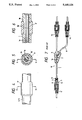
- FIG. 1 is a partly-broken, plan view of a preferred embodiment of a wire harness of the present invention
- FIG. 2 is an enlarged cross-sectional view taken along the line II--II of FIG. 1;
- FIG. 3 is a fragmentary cross-sectional view taken along the line III--III of FIG. 2;
- FIG. 4 is an enlarged plan view of an important portion of another embodiment of the invention.
- FIG. 5 is a cross-sectional view taken along the line V--V of FIG. 4;
- FIG. 6 is a cross-sectional view taken along the line VI--VI of FIG. 5;
- FIG. 7 is a view illustrative of a conventional wire harness.
- FIG. 1 is a partly-broken, plan view of a preferred embodiment of a wire harness of the present invention.
- FIG. 2 is an enlarged cross-sectional view taken along the line II--II of FIG. 1.
- FIG. 3 is a fragmentary cross-sectional view taken along the line III--III of FIG. 2.
- a wire 1' is branch-connected to an intermediate portion of an electrically insulatively-covered wire 1 (which constitutes a wire harness W') by a crimp-style terminal 2.
- a waterproof seal 3 is provided on this connecting portion, and waterproof connectors 4 1 , 4 2 and 4 3 are connected to the opposite ends of the wire 1 and the end of the wire 1'. This construction is similar to that shown in FIG. 7.
- a portion of an electrically-insulative covering or sheath 1b of the wire 1 (1') is melted or fused between the above branch connecting portion (where the waterproof seal 3 is provided) and the waterproof connector 4 1 (4 2 , 4 3 ), and is filled in gaps between conductors 1a within the wire, and is solidified to close these gaps, as shown in FIGS. 2 and 3.
- a closure portion 10 closing the gaps between the conductors 1a is formed and the intrusion of water toward the waterproof connector is prevented by the closure portion 10.
- the fusing treatment applied to the electrically-insulative covering 1b is carried out by a known method, such as a high-frequency fusion and ultrasonic fusion.
- the fused portion of this covering is thinned as at 1b', and is lowered in strength and electrical insulation. Therefore, it is preferred that a protective layer 9 be provided on this thinned portion.
- the protective layer 9 comprises an electrically-insulative tape wound on the thinned portion
- any other suitable means such as a heat shrinkable tube or sheet may be used.
- Another alternative is a synthetic resin tube (later described) bonded to the thinned portion by an adhesive.
- the closure portion 10 formed by fusing the electrically-insulative covering 1b may be disposed at any position between the waterproof seal 3 and the waterproof connector 4 1 , but it is preferred that the closure portion 10 be positioned as close to the connector 4 1 as possible.
- FIGS. 4 to 6 show another embodiment of the invention in which the fusion or melting of the electrically-insulative covering 1b and the formation of the protective layer 9 are carried out at the same time.
- a soft or rigid synthetic resin tube 9' is fitted on the wire 1 (1'), and simultaneously with the fusion of the tube 9' to the wire, the electrically-insulative covering 1b is fused to form the above closure portion 10.
- the material of the tube 9' and the fusing method should be changed depending on the kind of the electrically-insulative covering of the wire 1 (1').
- Table 1 shows preferred examples of combinations.
- the tube 9' is not limited to a tubular shape, but may be of the semi-split type having slits or of the complete half-split type.
- the closure portion closing the gaps between the conductors within the wire so as to prevent the intrusion of water is formed. Therefore, even when water intrudes from the branch connecting portion, the penetration of the water into the waterproof connector is prevented, thereby preventing such troubles as the corrosion of the contact portion, an imperfect electrical conductivity, and a short-circuiting between the terminals, thus providing the wire harness of a high reliability.
Abstract
Description
              TABLE 1
______________________________________
Material for
insulative covering
              Material for tube
                            Fusion method
______________________________________
Polyvinyl chloride
              P.V.C         High-frequency
                            fusion
Polyethylene  Polyethylene  Ultrasonic
                            fusion
______________________________________
Claims (6)
Applications Claiming Priority (2)
| Application Number | Priority Date | Filing Date | Title |
|---|---|---|---|
| JP2076748A JPH03280365A (en) | 1990-03-28 | 1990-03-28 | Waterproof seal structure of wire hardness |
| JP2-76748 | 1990-03-28 |
Publications (1)
| Publication Number | Publication Date |
|---|---|
| US5168124A true US5168124A (en) | 1992-12-01 |
Family
ID=13614222
Family Applications (1)
| Application Number | Title | Priority Date | Filing Date |
|---|---|---|---|
| US07/670,837 Expired - Fee Related US5168124A (en) | 1990-03-28 | 1991-03-18 | Waterproof seal construction for wire harness |
Country Status (2)
| Country | Link |
|---|---|
| US (1) | US5168124A (en) |
| JP (1) | JPH03280365A (en) |
Cited By (35)
| Publication number | Priority date | Publication date | Assignee | Title |
|---|---|---|---|---|
| US5438163A (en) * | 1992-12-09 | 1995-08-01 | Rxs Schrumpftechnik Garnituren Gmbh | Blockstop for longitudinal sealing of a cable and a method of forming the blockstop |
| US5536904A (en) * | 1993-05-24 | 1996-07-16 | Sumitomo Wiring Systems, Ltd. | Waterproof construction of wire |
| US5917151A (en) * | 1997-08-29 | 1999-06-29 | Ut Automotive Dearborn, Inc. | Multi-shot molds for manufacturing wire harnesses |
| US5937950A (en) * | 1996-12-02 | 1999-08-17 | Medex, Inc. | Cable system for medical equipment |
| US5973265A (en) * | 1997-08-29 | 1999-10-26 | Lear Automotive Dearborn, Inc. | Wire harness with splice locators |
| US6011318A (en) * | 1998-04-16 | 2000-01-04 | Lear Automotive Dearborn, Inc. | Wire harness for vehicle seat |
| US6027679A (en) * | 1997-08-29 | 2000-02-22 | Lear Automotive Dearborn, Inc. | Method for securing a wire harness to a surface |
| US6069319A (en) * | 1997-07-22 | 2000-05-30 | Lear Automotive Dearborn, Inc. | Foamed-in harnesses |
| US6071446A (en) * | 1997-08-29 | 2000-06-06 | Lear Automotive Dearborn, Inc | Method for centering wire harness in mold |
| US6086037A (en) * | 1997-08-29 | 2000-07-11 | Lear Automotive Dearborn, Inc | Mold for assembling and forming wire harness |
| US6107569A (en) * | 1998-05-12 | 2000-08-22 | Shields; Scott D. | Foam wire harness in a pillar |
| US6120327A (en) * | 1997-07-22 | 2000-09-19 | Lear Automotive Dearborn, Inc. | Foam wire harness with shape memory |
| US6126228A (en) * | 1997-09-11 | 2000-10-03 | Lear Automotive Dearborn, Inc. | Wire harness foamed to trim panel |
| US6358083B1 (en) * | 1998-09-30 | 2002-03-19 | Steelcase Development Corporation | Communications cabling system with serially connectable unique cable assemblies |
| EP1211142A2 (en) * | 2000-11-29 | 2002-06-05 | Sumitomo Wiring Systems, Ltd. | Waterproof structure for a wire harness |
| US6486407B1 (en) * | 2001-06-14 | 2002-11-26 | Trident Design Llc | Power strip with adjustable outlets |
| US20080070432A1 (en) * | 2005-03-31 | 2008-03-20 | United Parcel Service Of America, Inc. | Relay retrofit apparatus having an electrically-activated relay switch for retrofitting an electrical system |
| US20080277607A1 (en) * | 2007-05-11 | 2008-11-13 | Yazaki Corporation | Water stopping configuration of linear members and method of water stopping the linear members |
| US20100090851A1 (en) * | 2008-09-30 | 2010-04-15 | Bruce Hauser | Electrical extension cord |
| US20100139733A1 (en) * | 2009-08-18 | 2010-06-10 | General Electric Company | Fused wiring harness for a photovoltaic system |
| US20100230159A1 (en) * | 2009-03-12 | 2010-09-16 | Samsung Electronics Co., Ltd. | Signal transfer apparatus |
| US20110045697A1 (en) * | 2008-05-08 | 2011-02-24 | Sumitomo Wiring Systems, Ltd. | Water stop structure for wire harness and method of forming water stop section |
| US20110180962A1 (en) * | 2010-01-25 | 2011-07-28 | Apple Inc. | Molded cable structures and systems and methods for making the same |
| US8276523B2 (en) | 2008-05-28 | 2012-10-02 | Steelcase Inc. | Worksurface assembly |
| US20130098660A1 (en) * | 2010-08-09 | 2013-04-25 | Autonetworks Technologies, Ltd. | Electric wire protection structure and method for manufacturing electric wire protection structure |
| US8653365B1 (en) * | 2009-01-23 | 2014-02-18 | Claude W. Mixon | Overfill warning wiring system for tank trucks |
| US20170274843A1 (en) * | 2016-03-22 | 2017-09-28 | Yazaki Corporation | Wire harness |
| US20170313265A1 (en) * | 2014-10-31 | 2017-11-02 | Sumitomo Wiring Systems, Ltd. | Cable harness |
| US20180166799A1 (en) * | 2015-05-11 | 2018-06-14 | Autonetworks Technologies, Ltd. | Heat-shrinkable tube attachment jig, method for manufacturing heat-shrinkable tube-equipped wire, and heat-shrinkable tube-equipped wire |
| US10103478B1 (en) * | 2017-06-23 | 2018-10-16 | Amazon Technologies, Inc. | Water resistant connectors with conductive elements |
| NL2020794B1 (en) * | 2018-04-19 | 2019-10-28 | Gebr Geers B V | ELECTRIC MAIN WIRE WITH BRANCH |
| US20200105441A1 (en) * | 2018-09-28 | 2020-04-02 | Sumitomo Wiring Systems, Ltd. | Wiring member |
| US11120923B2 (en) * | 2018-10-09 | 2021-09-14 | Sumitomo Wiring Systems, Ltd. | Wiring member |
| US11183791B2 (en) * | 2018-03-30 | 2021-11-23 | Autonetworks Technologies, Ltd. | Wire harness with elastic tube |
| US11347008B2 (en) | 2005-04-19 | 2022-05-31 | Commscope Technologies Llc | Fiber optic connection device with ruggedized tethers |
Families Citing this family (1)
| Publication number | Priority date | Publication date | Assignee | Title |
|---|---|---|---|---|
| JP6172067B2 (en) * | 2014-06-27 | 2017-08-02 | 住友電装株式会社 | Waterproof connector |
Citations (11)
| Publication number | Priority date | Publication date | Assignee | Title |
|---|---|---|---|---|
| US3321558A (en) * | 1962-10-08 | 1967-05-23 | Cavitron Ultrasonics Inc | Ultrasonic heating method |
| US3340112A (en) * | 1963-02-04 | 1967-09-05 | Reliance Cords & Cables Ltd | Method of making multi-conductor telephone cables with axially spaced water barriers |
| US3347974A (en) * | 1964-07-29 | 1967-10-17 | Siemens Ag | Moisture protection in communication cables whose cores are composed of conductors insulated with synthetic plastic, and method of producing such moisture protection |
| US3839596A (en) * | 1973-05-07 | 1974-10-01 | Amp Inc | Flexible airtight stranded wire |
| US4017772A (en) * | 1975-05-22 | 1977-04-12 | Ernest Burnside | Turn signal wiring replacement harness |
| US4461736A (en) * | 1980-04-15 | 1984-07-24 | The Furukawa Electric Co., Ltd. | Method of producing a dam for a communication cable |
| JPS61107165A (en) * | 1984-10-30 | 1986-05-26 | Mitsubishi Electric Corp | Apparatus for detecting speed of motor |
| JPS62222515A (en) * | 1986-03-24 | 1987-09-30 | 矢崎総業株式会社 | Moisture proof wiring harness and formation of the same |
| US4793877A (en) * | 1987-05-28 | 1988-12-27 | Thomas & Betts Corporation | Method for preventing water from tracking into a cable splice area |
| JPS6459467A (en) * | 1987-08-31 | 1989-03-07 | Alps Electric Co Ltd | Image input/output device |
| US4961961A (en) * | 1987-04-23 | 1990-10-09 | Dow Corning Corporation | Silicone water block for electrical cable |
-
1990
- 1990-03-28 JP JP2076748A patent/JPH03280365A/en active Pending
-
1991
- 1991-03-18 US US07/670,837 patent/US5168124A/en not_active Expired - Fee Related
Patent Citations (11)
| Publication number | Priority date | Publication date | Assignee | Title |
|---|---|---|---|---|
| US3321558A (en) * | 1962-10-08 | 1967-05-23 | Cavitron Ultrasonics Inc | Ultrasonic heating method |
| US3340112A (en) * | 1963-02-04 | 1967-09-05 | Reliance Cords & Cables Ltd | Method of making multi-conductor telephone cables with axially spaced water barriers |
| US3347974A (en) * | 1964-07-29 | 1967-10-17 | Siemens Ag | Moisture protection in communication cables whose cores are composed of conductors insulated with synthetic plastic, and method of producing such moisture protection |
| US3839596A (en) * | 1973-05-07 | 1974-10-01 | Amp Inc | Flexible airtight stranded wire |
| US4017772A (en) * | 1975-05-22 | 1977-04-12 | Ernest Burnside | Turn signal wiring replacement harness |
| US4461736A (en) * | 1980-04-15 | 1984-07-24 | The Furukawa Electric Co., Ltd. | Method of producing a dam for a communication cable |
| JPS61107165A (en) * | 1984-10-30 | 1986-05-26 | Mitsubishi Electric Corp | Apparatus for detecting speed of motor |
| JPS62222515A (en) * | 1986-03-24 | 1987-09-30 | 矢崎総業株式会社 | Moisture proof wiring harness and formation of the same |
| US4961961A (en) * | 1987-04-23 | 1990-10-09 | Dow Corning Corporation | Silicone water block for electrical cable |
| US4793877A (en) * | 1987-05-28 | 1988-12-27 | Thomas & Betts Corporation | Method for preventing water from tracking into a cable splice area |
| JPS6459467A (en) * | 1987-08-31 | 1989-03-07 | Alps Electric Co Ltd | Image input/output device |
Cited By (54)
| Publication number | Priority date | Publication date | Assignee | Title |
|---|---|---|---|---|
| US5438163A (en) * | 1992-12-09 | 1995-08-01 | Rxs Schrumpftechnik Garnituren Gmbh | Blockstop for longitudinal sealing of a cable and a method of forming the blockstop |
| US5536904A (en) * | 1993-05-24 | 1996-07-16 | Sumitomo Wiring Systems, Ltd. | Waterproof construction of wire |
| US5937950A (en) * | 1996-12-02 | 1999-08-17 | Medex, Inc. | Cable system for medical equipment |
| US6069319A (en) * | 1997-07-22 | 2000-05-30 | Lear Automotive Dearborn, Inc. | Foamed-in harnesses |
| US6120327A (en) * | 1997-07-22 | 2000-09-19 | Lear Automotive Dearborn, Inc. | Foam wire harness with shape memory |
| US5917151A (en) * | 1997-08-29 | 1999-06-29 | Ut Automotive Dearborn, Inc. | Multi-shot molds for manufacturing wire harnesses |
| US5973265A (en) * | 1997-08-29 | 1999-10-26 | Lear Automotive Dearborn, Inc. | Wire harness with splice locators |
| US6027679A (en) * | 1997-08-29 | 2000-02-22 | Lear Automotive Dearborn, Inc. | Method for securing a wire harness to a surface |
| US6071446A (en) * | 1997-08-29 | 2000-06-06 | Lear Automotive Dearborn, Inc | Method for centering wire harness in mold |
| US6086037A (en) * | 1997-08-29 | 2000-07-11 | Lear Automotive Dearborn, Inc | Mold for assembling and forming wire harness |
| US6126228A (en) * | 1997-09-11 | 2000-10-03 | Lear Automotive Dearborn, Inc. | Wire harness foamed to trim panel |
| US6011318A (en) * | 1998-04-16 | 2000-01-04 | Lear Automotive Dearborn, Inc. | Wire harness for vehicle seat |
| US6107569A (en) * | 1998-05-12 | 2000-08-22 | Shields; Scott D. | Foam wire harness in a pillar |
| US6358083B1 (en) * | 1998-09-30 | 2002-03-19 | Steelcase Development Corporation | Communications cabling system with serially connectable unique cable assemblies |
| EP1211142A2 (en) * | 2000-11-29 | 2002-06-05 | Sumitomo Wiring Systems, Ltd. | Waterproof structure for a wire harness |
| EP1211142A3 (en) * | 2000-11-29 | 2003-04-16 | Sumitomo Wiring Systems, Ltd. | Waterproof structure for a wire harness |
| US6486407B1 (en) * | 2001-06-14 | 2002-11-26 | Trident Design Llc | Power strip with adjustable outlets |
| US20080070432A1 (en) * | 2005-03-31 | 2008-03-20 | United Parcel Service Of America, Inc. | Relay retrofit apparatus having an electrically-activated relay switch for retrofitting an electrical system |
| US11347008B2 (en) | 2005-04-19 | 2022-05-31 | Commscope Technologies Llc | Fiber optic connection device with ruggedized tethers |
| US20080277607A1 (en) * | 2007-05-11 | 2008-11-13 | Yazaki Corporation | Water stopping configuration of linear members and method of water stopping the linear members |
| US8076572B2 (en) * | 2007-05-11 | 2011-12-13 | Yazaki Corporation | Water stopping configuration of linear members and method of water stopping the linear members |
| US8403690B2 (en) * | 2008-05-08 | 2013-03-26 | Sumitomo Wiring Systems, Ltd. | Water stop structure for wire harness and method of forming water stop section |
| US20110045697A1 (en) * | 2008-05-08 | 2011-02-24 | Sumitomo Wiring Systems, Ltd. | Water stop structure for wire harness and method of forming water stop section |
| US8276523B2 (en) | 2008-05-28 | 2012-10-02 | Steelcase Inc. | Worksurface assembly |
| US8701568B2 (en) | 2008-05-28 | 2014-04-22 | Steelcase Inc. | Rail and desk with sliding top and power access (C:SCAPE) |
| US20100090851A1 (en) * | 2008-09-30 | 2010-04-15 | Bruce Hauser | Electrical extension cord |
| US8653365B1 (en) * | 2009-01-23 | 2014-02-18 | Claude W. Mixon | Overfill warning wiring system for tank trucks |
| US9118877B2 (en) | 2009-03-12 | 2015-08-25 | Samsung Electronics Co., Ltd. | Signal transfer apparatus |
| US20100230159A1 (en) * | 2009-03-12 | 2010-09-16 | Samsung Electronics Co., Ltd. | Signal transfer apparatus |
| US9282276B2 (en) | 2009-03-12 | 2016-03-08 | Samsung Electronics Co., Ltd. | Signal transfer apparatus |
| US8710370B2 (en) * | 2009-03-12 | 2014-04-29 | Samsung Electronics Co., Ltd. | Signal transfer apparatus |
| US8895855B2 (en) | 2009-03-12 | 2014-11-25 | Samsung Electronics Co., Ltd. | Signal transfer apparatus |
| US20100139733A1 (en) * | 2009-08-18 | 2010-06-10 | General Electric Company | Fused wiring harness for a photovoltaic system |
| US8562890B2 (en) * | 2010-01-25 | 2013-10-22 | Apple Inc. | Method for molding a cable structure |
| US9640967B2 (en) | 2010-01-25 | 2017-05-02 | Apple Inc. | Method for molding a cable structure |
| US20110180962A1 (en) * | 2010-01-25 | 2011-07-28 | Apple Inc. | Molded cable structures and systems and methods for making the same |
| US20130098660A1 (en) * | 2010-08-09 | 2013-04-25 | Autonetworks Technologies, Ltd. | Electric wire protection structure and method for manufacturing electric wire protection structure |
| US10576915B2 (en) | 2014-10-31 | 2020-03-03 | Sumitomo Wiring Systems, Ltd. | Cable harness |
| US11400874B2 (en) | 2014-10-31 | 2022-08-02 | Sumitomo Wiring Systems, Ltd. | Cable harness with a water-sealing portion |
| US20170313265A1 (en) * | 2014-10-31 | 2017-11-02 | Sumitomo Wiring Systems, Ltd. | Cable harness |
| US11021116B2 (en) * | 2014-10-31 | 2021-06-01 | Sumitomo Wiring Systems, Ltd. | Cable harness |
| US10821919B2 (en) * | 2014-10-31 | 2020-11-03 | Sumitomo Wiring Systems, Ltd. | Cable harness with water sealing portion |
| US10399515B2 (en) * | 2014-10-31 | 2019-09-03 | Sumitomo Wiring Systems, Ltd. | Cable harness with sheath housing cables |
| US20180166799A1 (en) * | 2015-05-11 | 2018-06-14 | Autonetworks Technologies, Ltd. | Heat-shrinkable tube attachment jig, method for manufacturing heat-shrinkable tube-equipped wire, and heat-shrinkable tube-equipped wire |
| US10069220B2 (en) * | 2015-05-11 | 2018-09-04 | Autonetworks Technologies, Ltd. | Heat-shrinkable tube attachment jig, method for manufacturing heat-shrinkable tube-equipped wire, and heat-shrinkable tube-equipped wire |
| US10189422B2 (en) * | 2016-03-22 | 2019-01-29 | Yazaki Corporation | Wire harness |
| US20170274843A1 (en) * | 2016-03-22 | 2017-09-28 | Yazaki Corporation | Wire harness |
| US10103478B1 (en) * | 2017-06-23 | 2018-10-16 | Amazon Technologies, Inc. | Water resistant connectors with conductive elements |
| US11183791B2 (en) * | 2018-03-30 | 2021-11-23 | Autonetworks Technologies, Ltd. | Wire harness with elastic tube |
| NL2020794B1 (en) * | 2018-04-19 | 2019-10-28 | Gebr Geers B V | ELECTRIC MAIN WIRE WITH BRANCH |
| BE1026189B1 (en) * | 2018-04-19 | 2020-04-06 | Gebr Geers B V | ELECTRIC MAIN PIPE WITH BRANCH |
| US20200105441A1 (en) * | 2018-09-28 | 2020-04-02 | Sumitomo Wiring Systems, Ltd. | Wiring member |
| US11342096B2 (en) * | 2018-09-28 | 2022-05-24 | Sumitomo Wiring Systems, Ltd. | Wiring member with resin molded portions and bracket |
| US11120923B2 (en) * | 2018-10-09 | 2021-09-14 | Sumitomo Wiring Systems, Ltd. | Wiring member |
Also Published As
| Publication number | Publication date |
|---|---|
| JPH03280365A (en) | 1991-12-11 |
Similar Documents
| Publication | Publication Date | Title |
|---|---|---|
| US5168124A (en) | Waterproof seal construction for wire harness | |
| US6376773B1 (en) | Structure for connecting electrical cables to a flat electrical cable | |
| US3995964A (en) | Heat recoverable article | |
| US3410950A (en) | Insulated moisture-proof connecting device | |
| EP0725985B1 (en) | Wire connector | |
| US5315065A (en) | Versatile electrically insulating waterproof connectors | |
| US4734059A (en) | In-line fuse holder | |
| US20010052420A1 (en) | Crimping terminal for connection between electric cables | |
| JP2015222713A (en) | Method for splice connection of shielded wire cable and cable made by the same | |
| JPH08223757A (en) | Method and structure for protecting conduction joint of flat cable | |
| JP2006156052A (en) | Connection structure of high voltage electric cable, and connection method of high voltage electric cable | |
| JPH05161240A (en) | Joint and terminal of cable | |
| US5711685A (en) | Electrical connector having removable seal at cable entry end | |
| US5369225A (en) | Wire connector | |
| JP3311638B2 (en) | Waterproofing method of coated conductor lead-out part | |
| US20140174822A1 (en) | Waterproof seal for electrical assemblies | |
| US20170169919A1 (en) | Wire harness and method for manufacturing same | |
| US3685006A (en) | Cable connector | |
| US3377422A (en) | Splice assembly to connect cable ends together | |
| US2839636A (en) | Electrical connection | |
| JPH07106014A (en) | Connector | |
| JPH0945380A (en) | Splice structure of wire harness | |
| WO2001009990A1 (en) | Cable connector | |
| JPS5832380A (en) | Method of connecting waterproof cable | |
| US4264780A (en) | Heat-recoverable articles |
Legal Events
| Date | Code | Title | Description |
|---|---|---|---|
| AS | Assignment |
Owner name: YAZAKI CORPORATION, NO. 4-28, MITA 1-CHOME, MINATO Free format text: ASSIGNMENT OF ASSIGNORS INTEREST.;ASSIGNORS:TAKASE, HIRAJI;IIZUKA, TOSHIO;REEL/FRAME:005645/0501 Effective date: 19910311 |
|
| FEPP | Fee payment procedure |
Free format text: PAYOR NUMBER ASSIGNED (ORIGINAL EVENT CODE: ASPN); ENTITY STATUS OF PATENT OWNER: LARGE ENTITY |
|
| FPAY | Fee payment |
Year of fee payment: 4 |
|
| FEPP | Fee payment procedure |
Free format text: PAYOR NUMBER ASSIGNED (ORIGINAL EVENT CODE: ASPN); ENTITY STATUS OF PATENT OWNER: LARGE ENTITY Free format text: PAYER NUMBER DE-ASSIGNED (ORIGINAL EVENT CODE: RMPN); ENTITY STATUS OF PATENT OWNER: LARGE ENTITY |
|
| FPAY | Fee payment |
Year of fee payment: 8 |
|
| REMI | Maintenance fee reminder mailed | ||
| LAPS | Lapse for failure to pay maintenance fees | ||
| STCH | Information on status: patent discontinuation |
Free format text: PATENT EXPIRED DUE TO NONPAYMENT OF MAINTENANCE FEES UNDER 37 CFR 1.362 |
|
| FP | Lapsed due to failure to pay maintenance fee |
Effective date: 20041201 |