US5175474A - Power source for lighting apparatus - Google Patents
Power source for lighting apparatus Download PDFInfo
- Publication number
- US5175474A US5175474A US07/765,936 US76593691A US5175474A US 5175474 A US5175474 A US 5175474A US 76593691 A US76593691 A US 76593691A US 5175474 A US5175474 A US 5175474A
- Authority
- US
- United States
- Prior art keywords
- discharge lamp
- circuit
- winding
- operating discharge
- switching
- Prior art date
- Legal status (The legal status is an assumption and is not a legal conclusion. Google has not performed a legal analysis and makes no representation as to the accuracy of the status listed.)
- Expired - Fee Related
Links
Images


Classifications
-
- H—ELECTRICITY
- H05—ELECTRIC TECHNIQUES NOT OTHERWISE PROVIDED FOR
- H05B—ELECTRIC HEATING; ELECTRIC LIGHT SOURCES NOT OTHERWISE PROVIDED FOR; CIRCUIT ARRANGEMENTS FOR ELECTRIC LIGHT SOURCES, IN GENERAL
- H05B41/00—Circuit arrangements or apparatus for igniting or operating discharge lamps
- H05B41/14—Circuit arrangements
- H05B41/26—Circuit arrangements in which the lamp is fed by power derived from dc by means of a converter, e.g. by high-voltage dc
- H05B41/28—Circuit arrangements in which the lamp is fed by power derived from dc by means of a converter, e.g. by high-voltage dc using static converters
- H05B41/282—Circuit arrangements in which the lamp is fed by power derived from dc by means of a converter, e.g. by high-voltage dc using static converters with semiconductor devices
- H05B41/2825—Circuit arrangements in which the lamp is fed by power derived from dc by means of a converter, e.g. by high-voltage dc using static converters with semiconductor devices by means of a bridge converter in the final stage
- H05B41/2828—Circuit arrangements in which the lamp is fed by power derived from dc by means of a converter, e.g. by high-voltage dc using static converters with semiconductor devices by means of a bridge converter in the final stage using control circuits for the switching elements
-
- Y—GENERAL TAGGING OF NEW TECHNOLOGICAL DEVELOPMENTS; GENERAL TAGGING OF CROSS-SECTIONAL TECHNOLOGIES SPANNING OVER SEVERAL SECTIONS OF THE IPC; TECHNICAL SUBJECTS COVERED BY FORMER USPC CROSS-REFERENCE ART COLLECTIONS [XRACs] AND DIGESTS
- Y10—TECHNICAL SUBJECTS COVERED BY FORMER USPC
- Y10S—TECHNICAL SUBJECTS COVERED BY FORMER USPC CROSS-REFERENCE ART COLLECTIONS [XRACs] AND DIGESTS
- Y10S315/00—Electric lamp and discharge devices: systems
- Y10S315/05—Starting and operating circuit for fluorescent lamp
-
- Y—GENERAL TAGGING OF NEW TECHNOLOGICAL DEVELOPMENTS; GENERAL TAGGING OF CROSS-SECTIONAL TECHNOLOGIES SPANNING OVER SEVERAL SECTIONS OF THE IPC; TECHNICAL SUBJECTS COVERED BY FORMER USPC CROSS-REFERENCE ART COLLECTIONS [XRACs] AND DIGESTS
- Y10—TECHNICAL SUBJECTS COVERED BY FORMER USPC
- Y10S—TECHNICAL SUBJECTS COVERED BY FORMER USPC CROSS-REFERENCE ART COLLECTIONS [XRACs] AND DIGESTS
- Y10S315/00—Electric lamp and discharge devices: systems
- Y10S315/07—Starting and control circuits for gas discharge lamp using transistors
Definitions
- the present invention relates generally to an appratus for operating discharge lamp, and more particularly, to an appratus for operating discharge lamp with a high frequency power source.
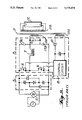
- FIG. 1 shows an example of conventional apparatus for operating discharge lamps.
- the apparatus for operating discharge lamps has a rectifier 2, a smoothing circuit 3, an inverter circuit 4, an output transformer 11 and a discharge lamp 12.
- the rectifier 2 is adapted for rectifying a commercial frequency power, such as a 50/60 Hz, 100/200 V power from a commercial power supply 1.
- the rectified signal from the rectifier 2 is supplied to the inverter circuit 4 through the smoothing circuit 3.
- the smoothing circuit 3 removes undesired ripples from the rectified signal.
- the rectifier 2 is a full-wave rectifier.
- the smoothing circuit 3 is a voltage-split type smoothing circuit. The full-wave rectifier and the voltage-split type smoothing circuit are well-known in the art, so that detailed descriptions thereof are omitted herein.
- the output transformer 11 includes a primary winding 11a and a secondry winding 11b.
- the inverter circuit 4 includes a series circuit of FETs 5 and 6, a choke 7, a control circuit 8, a capacitor 9, a diode 10 and a series circuit of coupling capacitors 17a and 17b.
- the series circuit of FETs 5 and 6 provides a switching operation for the rectified voltage from the smoothing circuit 3.
- the choke 7 has a primary winding 7a and a secondary winding 7b.
- the series circuit of the FETs 5, 6 and the series circuit of the coupling capacitors 17a, 17b are respectively connected across the rectifier 2.
- the gates of the FETs 5, 6 are connected to outputs of the control circuit 8 so that they are alternately turned ON or OFF at a high frequency under a control of the control circuit 8.
- the primary winding 11a of the output transformer 11 is coupled between the coupling node of the FETs 5, 6 and the coupling node of the coupling capacitors 17a and 17b through the choke 7.
- the secondary winding 11b is connected to the discharge lamp 12.
- the capacitor 9 is coupled across the primary winding 11a of the output transformer 11.
- a rectified voltage is inputted to the control circuit 8 as a DC power source.
- the regulated high frequency AC current is outputted to the discharge lamp 12 through the output transformer 11.
- the primary winding 11a is connected in parallel with the capacitor 9 so that a boosted high frequency AC voltage is generated on the second winding 11b for lighting the discharge lamp 12.
- the DC power source required for driving the control circuit 8 of the inverter circuit 4 is generated by the secondary winding 7b of the choke 7.
- FIG. 2 is a block diagram showing another example of the conventional apparatus for operating discharge lamp.
- This example differs from the above in that an additional winding 11c is coupled to the output transformer 11 in place of the secondary winding 7b of the choke 7.
- the DC power, required for the control circuit 8 is generated at the additional winding 11c of the output transformer 11.
- the DC power source for the control circuit 8 is obtained from the secondary windings 7b of the choke 7 or the additional winding 11c of the output transformer 11. Therefore, if the high frequency AC current flowing through the choke 7 and the transformer 11 has changed, the DC power source to the control circuit 8 also changes in response to the change and interferes with the stable operation of the control circuit 8.
- an object of the present invention to provide an appratus for operating a discharge lamp which is able to stably light a discharge lamp.
- Another object of the present invention is to provide an appratus for operating discharge lamp which is able to generate a stable DC power source for a control circuit of an inverter circuit.
- an appratus for operating discharge lamp includes a source of electrical power, switching devices for switching the electrical power, a control circuit for controlling the switching devices, a transformer having a primary winding for receiving the electrical power switched by the switching devices and a secondary winding for supplying power to the lighting apparatus, a resonant circuit including an inductor and a capacitor for regulating the frequency of the electrical power and a circuit for powering the control circuit, the powering circuit including a secondary winding on the inductor and an additional winding on the transformer connected in a differential manner.
- FIGS. 1 and 2 are schematic diagrams showing examples of conventional apparatus for operating discharge lamp
- FIG. 3 is a block diagram showing an embodiment of the apparatus for operating discharge lamp according to the present invention.
- FIGS. 4a-c in an explanatory diagram showing voltage by the secondary windings and their differential voltage
- FIG. 5 is the block diagram showing a first modification of this embodiment.
- FIG. 6 is the block diagram showing a second modification of this embodiment.
- FIGS. 3 through 6 Reference numerals or letters used in FIGS. 1 and 2 will be used to designate like or equivalent elements for simplicity of explanation.
- the apparatus for operating discharge lamp has a rectifier 2, a smoothing circuit 3, an inverter circuit 4, an output transformer 11 and a discharge lamp 12.
- the rectifier 2 is adapted for rectifying a commercial frequency power of 50/60 Hz, 100/200 V from a commercial power supply 1.
- the rectified voltage from the rectifier 2 is supplied to the inverter circuit 4 through the smoothing circuit 3.
- the smoothing circuit 3 removes undesired ripples in the rectified voltage.
- the rectifier 2 and the smoothing circuit 3 are well-known and identical with those in the conventional apparatus of FIGS. 1 and 2 so that detailed descriptions thereof are also omitted herein.
- the output transformer 11 includes a primary winding 11a, a secondary winding 11b and an additional winding 11c.
- the inverter circuit 4 includes a series circuit of FETs 5 and 6, a choke 7, a control circuit 8, a capacitor 9, a diode 10 and a series circuit of coupling capacitors 17a and 17b.
- the series circuit of FETs 5 and 6 provides a switching operation for the rectified voltage from the smoothing circuit 3.
- the choke 7 has a primary winding 7a and a secondary winding 7b.
- the series circuit of the FETs 5, 6 and the series circuit of the coupling capacitors 17a, 17b are respectively connected across the rectifier 3.
- the gates of the FETs 5, 6 are connected to outputs of the control circuit 8 so that they are alternately turned ON or OFF at a high frequency under control of the control circuit 8.
- the primary winding 11a of the output transformer 11 is coupled between the coupling node of the FETs 5, 6 and the coupling node of the coupling capacitors 17a and 17b through the choke 7.
- the secondary winding 11b is connected to the discharge lamp 12.
- the capacitor 9 is coupled across the primary winding 11a of the output transformer 11.
- An output voltage corresponding to the high frequency AC current is generated on the primary winding 11a of the output transformer 11.
- the secondary winding 7b of the choke 7 is coupled to inputs of the control circuit 8 through the diode 10 and the additional winding 11c of the output transformer 11.
- an induced voltage responsive to the high frequency AC current appears on the secondary winding 7b.
- Another induced voltage also responsive to the high frequency AC current appears on the additional winding 11c of the output transformer 11.
- the regulated high frequency AC current is output to the discharge lamp 12 through the output transformer 11.
- the primary winding 11a is connected in parallel with the capacitor 9 so that a boosted high frequency AC voltage is generated on the second winding 11b for lighting the discharge lamp 12.
- the secondary winding 7b of the choke 7 and the additional winding 11c of the output transformer 11 are connected together in series.
- the DC power source required for driving the control circuit 8 of the inverter circuit 4 is generated by both the secondary winding 7b of the choke 7 and the additional winding 11c of the output transformer 11.
- these windings 7b and 11c are coupled differentially in terms of winding polarity relation so that their induced voltages are differentially combined in this series circuit.
- the DC voltage Vdc of the DC power source is results from the differential combination of the induced voltages V1 and V2.
- the induced voltage V1 with, e.g., 32 V, the induced voltage V2 with, e.g., 20 V are combined and correspondingly a DC power source of 12 V is obtained, as shown in FIG. 4(A).
- the DC power source obtained by differential combination of the induced voltages V1 and V2 stays almost constant, or within a relatively short voltage range, e.g., the range from 10 V to 12 V.
- the smoothing circuit 3 is a voltage-split type smoothing circuit, similar to the examples of the conventional discharge lamp lighting apparatus as shown FIGS. 1 and 2.
- the smoothing circuit 3 is not limited to the voltage-split type smoothing circuit for example, the smoothing circuit 3 can be replaced by a single smoothing capacitor 15, as shown in FIG. 5.
- FIG. 5 shows a block diagram of a first modification of this embodiment.
- a dropping resistor 19 can be inserted in series with the diode 10, or a zener diode 16 can be couple across the inputs of the control circuit 8, for further stabilizing the DC power pource to be applied to the control circuit 8.
- FIG. 6 a second modification of the apparatus for operating discharge lamp will be briefly described below.
- this second modification differs from the above embodiment, e.g., the apparatus of FIG. 3 as follows. That is, an additional winding 11c is provided by using a part of the primary winding 11a of the transformer 11. Thus, a tap 11d provided on the primary winding 11a is coupled to the secondary winding 7b of the choke 7. Further, one end of the primary winding 11a of the transformer 11 is coupled with the connecting node of the FETs 5 and 6 through a coupling capacitor 17c as well as the choke 7, while another end of the primary winding 11a is directly coupled with only the other end of the FET 6.
- the apparatus for operating discharge lamps is advantageous for simplifying the construction in comparison to the embodiment of FIG. 3.
- the present invention can provide an extremely preferable apparatus for operating discharge lamp.
Abstract
An apparatus for operating discharge lamp. The apparatus includes a source of electrical power, switching devices for switching the electrical power, a control circuit for controlling the switching devices, a transformer having a primary winding for receiving the electrical power switched by the switching devices and a secondary winding for supplying power to the lighting apparatus, a resonant circuit including an inductor and a capacitor for regulating the frequency of the electrical power and a circuit for powering the control circuit, the powering circuit including a secondary winding on the inductor and an additional winding on the transformer connected in a differential manner.
Description
The present invention relates generally to an appratus for operating discharge lamp, and more particularly, to an appratus for operating discharge lamp with a high frequency power source.
An appratus for operating a discharge lamp is generally required for operating a discharge lamp. FIG. 1 shows an example of conventional apparatus for operating discharge lamps. The apparatus for operating discharge lamps has a rectifier 2, a smoothing circuit 3, an inverter circuit 4, an output transformer 11 and a discharge lamp 12. The rectifier 2 is adapted for rectifying a commercial frequency power, such as a 50/60 Hz, 100/200 V power from a commercial power supply 1.
The rectified signal from the rectifier 2 is supplied to the inverter circuit 4 through the smoothing circuit 3. The smoothing circuit 3 removes undesired ripples from the rectified signal. The rectifier 2 is a full-wave rectifier. The smoothing circuit 3 is a voltage-split type smoothing circuit. The full-wave rectifier and the voltage-split type smoothing circuit are well-known in the art, so that detailed descriptions thereof are omitted herein. The output transformer 11 includes a primary winding 11a and a secondry winding 11b.
The inverter circuit 4 includes a series circuit of FETs 5 and 6, a choke 7, a control circuit 8, a capacitor 9, a diode 10 and a series circuit of coupling capacitors 17a and 17b. The series circuit of FETs 5 and 6 provides a switching operation for the rectified voltage from the smoothing circuit 3. The choke 7 has a primary winding 7a and a secondary winding 7b. The series circuit of the FETs 5, 6 and the series circuit of the coupling capacitors 17a, 17b are respectively connected across the rectifier 2. The gates of the FETs 5, 6 are connected to outputs of the control circuit 8 so that they are alternately turned ON or OFF at a high frequency under a control of the control circuit 8. The primary winding 11a of the output transformer 11 is coupled between the coupling node of the FETs 5, 6 and the coupling node of the coupling capacitors 17a and 17b through the choke 7. The secondary winding 11b is connected to the discharge lamp 12. The capacitor 9 is coupled across the primary winding 11a of the output transformer 11.
Thus a high frequency AC current flows through a resonant circuit consisting of the primary winding 7a of the choke 7 and the capacitor 9. An output voltage corresponding to the high frequency AC current is produced on the primary winding 11a of the output transformer 11. The secondary winding 7b of the choke 7 is coupled to inputs of the control circuit 8 through the diode 10. Thus an induced voltage responsive to the high frequency AC current appears on the secondary winding 7b of the choke 7 and then rectified by the diode 10.
A rectified voltage is inputted to the control circuit 8 as a DC power source. The regulated high frequency AC current is outputted to the discharge lamp 12 through the output transformer 11. In the output transformer 11, the primary winding 11a is connected in parallel with the capacitor 9 so that a boosted high frequency AC voltage is generated on the second winding 11b for lighting the discharge lamp 12.
In the above example of the conventional apparatus for discharge lamp, the DC power source required for driving the control circuit 8 of the inverter circuit 4 is generated by the secondary winding 7b of the choke 7.
Further, FIG. 2 is a block diagram showing another example of the conventional apparatus for operating discharge lamp. This example differs from the above in that an additional winding 11c is coupled to the output transformer 11 in place of the secondary winding 7b of the choke 7. In this latter example, the DC power, required for the control circuit 8 is generated at the additional winding 11c of the output transformer 11.
In both these conventional apparatus for operating discharge lamp, the DC power source for the control circuit 8 is obtained from the secondary windings 7b of the choke 7 or the additional winding 11c of the output transformer 11. Therefore, if the high frequency AC current flowing through the choke 7 and the transformer 11 has changed, the DC power source to the control circuit 8 also changes in response to the change and interferes with the stable operation of the control circuit 8.
It is, therefore, an object of the present invention to provide an appratus for operating a discharge lamp which is able to stably light a discharge lamp.
Another object of the present invention is to provide an appratus for operating discharge lamp which is able to generate a stable DC power source for a control circuit of an inverter circuit.
In order to achieve the above objects, an appratus for operating discharge lamp according to one aspect of the present invention includes a source of electrical power, switching devices for switching the electrical power, a control circuit for controlling the switching devices, a transformer having a primary winding for receiving the electrical power switched by the switching devices and a secondary winding for supplying power to the lighting apparatus, a resonant circuit including an inductor and a capacitor for regulating the frequency of the electrical power and a circuit for powering the control circuit, the powering circuit including a secondary winding on the inductor and an additional winding on the transformer connected in a differential manner.
Additional objects and advantages of the present invention will be apparent to persons skilled in the art from a study of the following description and the accompanying drawings, which are hereby incorporated in and constitute a part of this specification.
A more complete appreciation of the present invention and many of the attendant advantages thereof will be readily obtained as the same becomes better understood by reference to the following detailed description when considered in connection with the accompanying drawings, wherein:
FIGS. 1 and 2 are schematic diagrams showing examples of conventional apparatus for operating discharge lamp;
FIG. 3 is a block diagram showing an embodiment of the apparatus for operating discharge lamp according to the present invention;
FIGS. 4a-c in an explanatory diagram showing voltage by the secondary windings and their differential voltage;
FIG. 5 is the block diagram showing a first modification of this embodiment; and
FIG. 6 is the block diagram showing a second modification of this embodiment.
The present invention will be described in detail with reference to the FIGS. 3 through 6. Throughout the drawings, reference numerals or letters used in FIGS. 1 and 2 will be used to designate like or equivalent elements for simplicity of explanation.
Referring now to FIG. 3, a first embodiment of the apparatus for operating discharge lamp according to the present invention will be described in detail. As shown in FIG. 3, the apparatus for operating discharge lamp has a rectifier 2, a smoothing circuit 3, an inverter circuit 4, an output transformer 11 and a discharge lamp 12. The rectifier 2 is adapted for rectifying a commercial frequency power of 50/60 Hz, 100/200 V from a commercial power supply 1. The rectified voltage from the rectifier 2 is supplied to the inverter circuit 4 through the smoothing circuit 3. The smoothing circuit 3 removes undesired ripples in the rectified voltage. The rectifier 2 and the smoothing circuit 3 are well-known and identical with those in the conventional apparatus of FIGS. 1 and 2 so that detailed descriptions thereof are also omitted herein. The output transformer 11 includes a primary winding 11a, a secondary winding 11b and an additional winding 11c.
The inverter circuit 4 includes a series circuit of FETs 5 and 6, a choke 7, a control circuit 8, a capacitor 9, a diode 10 and a series circuit of coupling capacitors 17a and 17b. The series circuit of FETs 5 and 6 provides a switching operation for the rectified voltage from the smoothing circuit 3. The choke 7 has a primary winding 7a and a secondary winding 7b. The series circuit of the FETs 5, 6 and the series circuit of the coupling capacitors 17a, 17b are respectively connected across the rectifier 3. The gates of the FETs 5, 6 are connected to outputs of the control circuit 8 so that they are alternately turned ON or OFF at a high frequency under control of the control circuit 8.
The primary winding 11a of the output transformer 11 is coupled between the coupling node of the FETs 5, 6 and the coupling node of the coupling capacitors 17a and 17b through the choke 7. The secondary winding 11b is connected to the discharge lamp 12. The capacitor 9 is coupled across the primary winding 11a of the output transformer 11. Thus a high frequency AC current flows through a resonant circuit consisting of the primary winding 7a of the choke 7 and the capacitor 9.
An output voltage corresponding to the high frequency AC current is generated on the primary winding 11a of the output transformer 11. The secondary winding 7b of the choke 7 is coupled to inputs of the control circuit 8 through the diode 10 and the additional winding 11c of the output transformer 11. Thus an induced voltage responsive to the high frequency AC current appears on the secondary winding 7b. Another induced voltage also responsive to the high frequency AC current appears on the additional winding 11c of the output transformer 11.
These two induced voltages are rectified by the diode 10, and then input to the control circuit 8 as a DC power source. The regulated high frequency AC current is output to the discharge lamp 12 through the output transformer 11. In the output transformer 11, the primary winding 11a is connected in parallel with the capacitor 9 so that a boosted high frequency AC voltage is generated on the second winding 11b for lighting the discharge lamp 12.
In this embodiment of the apparatus for operating discharge lamp, the secondary winding 7b of the choke 7 and the additional winding 11c of the output transformer 11 are connected together in series. Thus the DC power source required for driving the control circuit 8 of the inverter circuit 4 is generated by both the secondary winding 7b of the choke 7 and the additional winding 11c of the output transformer 11. However, these windings 7b and 11c are coupled differentially in terms of winding polarity relation so that their induced voltages are differentially combined in this series circuit.
Referring now to FIG. 4, the induced voltage V1 appearing on the secondary winding 7b of the choke 7, the induced voltage V2 appearing on the additional winding 11c of the output transformer 11 and the DC voltage Vdc of the DC power source to the control circuit 8 will be described in detail. The DC voltage Vdc of the DC power source is results from the differential combination of the induced voltages V1 and V2.
When the discharge lamp 12 is not loaded to the output transformer 11, a large amount of current flows through the primary winding 7a of the choke 7 and the primary winding 11a of the output transformer 11. Accordingly, the induced voltage V1 with, e.g., 32 V, the induced voltage V2 with, e.g., 20 V are combined and correspondingly a DC power source of 12 V is obtained, as shown in FIG. 4(A).
When the discharge lamp 12 is loaded to the output transformer 11, the high frequency AC current flowing through the primary winding 7a of the choke 7 and the primary winding 11a of the output transformer 11 decreases. Accordingly, the induced voltages V1 and V2 and the voltage Vdc of the DC power source decrease to 16 V, 6 V, and 10 V, respectively, as shown in FIG. 4(B).
Further, if both ends of the discharge lamp 12 are shorted, the induced voltages V1 and V2 decrease to 10 V and 0V, respectively, while the voltage Vdc of the DC power source remains voltage 10 V, the same as the load condition, as shown in FIG. 4(C).
As may be easily understood from the above description, even when the induced voltages V1 and V2 appearing on the windings 7a and 11c vary in response to load conditions, the DC power source obtained by differential combination of the induced voltages V1 and V2 stays almost constant, or within a relatively short voltage range, e.g., the range from 10 V to 12 V.
Therefore, it becomes possible to prevent a large fluctuation of the DC power source to the control circuit 8 so that the FETs 5 and 6 can be stably operated.
In the above embodiment, the smoothing circuit 3 is a voltage-split type smoothing circuit, similar to the examples of the conventional discharge lamp lighting apparatus as shown FIGS. 1 and 2. However, the smoothing circuit 3 is not limited to the voltage-split type smoothing circuit for example, the smoothing circuit 3 can be replaced by a single smoothing capacitor 15, as shown in FIG. 5. FIG. 5 shows a block diagram of a first modification of this embodiment.
Further, a dropping resistor 19 can be inserted in series with the diode 10, or a zener diode 16 can be couple across the inputs of the control circuit 8, for further stabilizing the DC power pource to be applied to the control circuit 8.
Referring now to FIG. 6, a second modification of the apparatus for operating discharge lamp will be briefly described below. As shown in FIG. 6, this second modification differs from the above embodiment, e.g., the apparatus of FIG. 3 as follows. That is, an additional winding 11c is provided by using a part of the primary winding 11a of the transformer 11. Thus, a tap 11d provided on the primary winding 11a is coupled to the secondary winding 7b of the choke 7. Further, one end of the primary winding 11a of the transformer 11 is coupled with the connecting node of the FETs 5 and 6 through a coupling capacitor 17c as well as the choke 7, while another end of the primary winding 11a is directly coupled with only the other end of the FET 6. In this modification, the apparatus for operating discharge lamps is advantageous for simplifying the construction in comparison to the embodiment of FIG. 3.
As described above, the present invention can provide an extremely preferable apparatus for operating discharge lamp.
While there have been illustrated and described what are at present considered to be preferred embodiments of the present invention, it will be understood by those skilled in the art that various changes and modifications may be made, and equivalents may be substituted for elements thereof without departing from the true scope of the present invention. In addition, many modifications may be made to adapt a particular situation or material to the teaching of the present invention without departing from the central scope thereof. Therefore, it is intended that the present invention not be limited to the particular embodiment disclosed as the best mode contemplated for carrying out the present invention, but that the present invention include all embodiments falling within the scope of the appended claims.
Claims (9)
1. An apparatus for operating discharge lamp, comprising:
a source of electrical power;
switching means for switching the electrical power;
control means for controlling the switching means;
transformer means having a primary winding for receiving the electrical power switched by the switching means and a secondary winding for supplying power to the lighting apparatus;
a resonant circuit including an inductor and a capacitor for regulating the frequency of the electrical power; and
a circuit for powering the control means, said circuit including a secondary winding on the inductor and an additional winding on the transformer means connected in a differential manner.
2. An apparatus for operating discharge lamp as in claim 1, wherein the additional winding on the transformer means comprises an additional tap onto the primary winding of the transformer means.
3. An apparatus for operating discharge lamp as in claim 1, further including a coupling circuit for coupling the electrical power from the switching means to the primary winding of the transformer means.
4. An apparatus for operating discharge lamp as in claim 1, wherein the coupling means includes at least one capacitor connected between the switching means and the transformer means.
5. An apparatus for operating discharge lamp as in claim 1, wherein the switching means comprises at least two switching elements connected in series, with their control terminals connected to the control means.
6. An apparatus for operating discharge lamp as in claim 5, wherein the switching elements comprises transistors.
7. An apparatus for operating discharge lamp as in claim 5, wherein the switching elements comprises FETs.
8. An apparatus for operating discharge lamp as in claim 1, wherein the circuit for powering the control means also includes means for stabilizing the voltage supplied to the control means.
9. An apparatus for operating discharge lamp as in claim 8, wherein the means for stabilizing includes a zener diode.
Applications Claiming Priority (2)
| Application Number | Priority Date | Filing Date | Title |
|---|---|---|---|
| JP2254101A JPH04138066A (en) | 1990-09-26 | 1990-09-26 | Device for lighting discharge lamp |
| JP2-254101 | 1990-09-26 |
Publications (1)
| Publication Number | Publication Date |
|---|---|
| US5175474A true US5175474A (en) | 1992-12-29 |
Family
ID=17260240
Family Applications (1)
| Application Number | Title | Priority Date | Filing Date |
|---|---|---|---|
| US07/765,936 Expired - Fee Related US5175474A (en) | 1990-09-26 | 1991-09-26 | Power source for lighting apparatus |
Country Status (6)
| Country | Link |
|---|---|
| US (1) | US5175474A (en) |
| EP (1) | EP0478306B1 (en) |
| JP (1) | JPH04138066A (en) |
| KR (1) | KR940009518B1 (en) |
| CA (1) | CA2052443A1 (en) |
| DE (1) | DE69108163T2 (en) |
Cited By (9)
| Publication number | Priority date | Publication date | Assignee | Title |
|---|---|---|---|---|
| WO1993023974A1 (en) * | 1992-05-20 | 1993-11-25 | Diablo Research Corporation | Stable power supply with high power factor |
| WO1994010823A1 (en) * | 1992-10-30 | 1994-05-11 | Motorola Lighting Inc. | A circuit for driving gas discharge lamps having protection against diode operation of the lamps |
| US5412287A (en) * | 1993-12-09 | 1995-05-02 | Motorola Lighting, Inc. | Circuit for powering a gas discharge lamp |
| WO1997022231A1 (en) * | 1995-12-08 | 1997-06-19 | Philips Electronics N.V. | Ballast system |
| WO1997022232A1 (en) * | 1995-12-08 | 1997-06-19 | Philips Electronics N.V. | Ballast system |
| US5737207A (en) * | 1995-03-29 | 1998-04-07 | Toshiba Lighting And Technology Corporation | Power supply |
| US5834884A (en) * | 1996-12-23 | 1998-11-10 | General Electric Company | Systematic configuration of compact fluorescent lamps for operation in a single-type ballast |
| US5982111A (en) * | 1994-09-30 | 1999-11-09 | Pacific Scientific Company | Fluorescent lamp ballast having a resonant output stage using a split resonating inductor |
| US6495969B1 (en) * | 1987-08-03 | 2002-12-17 | Ole K. Nilssen | Series-resonant ballast having overload control |
Families Citing this family (7)
| Publication number | Priority date | Publication date | Assignee | Title |
|---|---|---|---|---|
| KR940009511B1 (en) * | 1992-07-11 | 1994-10-14 | 금성계전주식회사 | Electronic stabilizer circuit for discharge lamp |
| JPH06196283A (en) * | 1992-12-22 | 1994-07-15 | Fuji Denki Kogyo Kk | Discharge lamp lighting control circuit |
| JP3329929B2 (en) * | 1994-02-15 | 2002-09-30 | 松下電工株式会社 | High pressure discharge lamp lighting device |
| DE29605087U1 (en) * | 1996-03-19 | 1996-08-08 | Trilux Lenze Gmbh & Co Kg | Fluorescent ballast with step-up converter |
| JP4629541B2 (en) * | 2005-09-26 | 2011-02-09 | スミダコーポレーション株式会社 | Discharge lamp drive control circuit |
| NZ600460A (en) | 2009-11-16 | 2014-11-28 | 300K Entpr Pty Ltd | Contactless coupling and method for use with an electrical appliance |
| JP6788562B2 (en) * | 2017-09-19 | 2020-11-25 | 株式会社東芝 | Receiver circuit and wireless communication device |
Citations (1)
| Publication number | Priority date | Publication date | Assignee | Title |
|---|---|---|---|---|
| US4709188A (en) * | 1985-12-23 | 1987-11-24 | General Electric Company | Operation of standby filament associated with an AC arc discharge lamp ballast |
Family Cites Families (5)
| Publication number | Priority date | Publication date | Assignee | Title |
|---|---|---|---|---|
| US4463286A (en) * | 1981-02-04 | 1984-07-31 | North American Philips Lighting Corporation | Lightweight electronic ballast for fluorescent lamps |
| US4459516A (en) * | 1981-07-06 | 1984-07-10 | Zelina William B | Line operated fluorescent lamp inverter ballast |
| DE3142613A1 (en) * | 1981-10-28 | 1983-05-05 | Philips Patentverwaltung Gmbh, 2000 Hamburg | Circuit arrangement for starting and operating a low-pressure mercury-vapour discharge lamp |
| DD257535A1 (en) * | 1984-11-07 | 1988-06-15 | Akad Wissenschaften Ddr | ELECTRONIC CONTROL UNIT FOR FLUORESCENT LAMPS |
| US5130610A (en) * | 1990-01-31 | 1992-07-14 | Toshiba Lighting & Technology Corporation | Discharge lamp lighting apparatus |
-
1990
- 1990-09-26 JP JP2254101A patent/JPH04138066A/en active Pending
-
1991
- 1991-09-25 EP EP91308749A patent/EP0478306B1/en not_active Expired - Lifetime
- 1991-09-25 KR KR1019910016709A patent/KR940009518B1/en not_active IP Right Cessation
- 1991-09-25 DE DE69108163T patent/DE69108163T2/en not_active Expired - Fee Related
- 1991-09-26 US US07/765,936 patent/US5175474A/en not_active Expired - Fee Related
- 1991-09-26 CA CA002052443A patent/CA2052443A1/en not_active Abandoned
Patent Citations (1)
| Publication number | Priority date | Publication date | Assignee | Title |
|---|---|---|---|---|
| US4709188A (en) * | 1985-12-23 | 1987-11-24 | General Electric Company | Operation of standby filament associated with an AC arc discharge lamp ballast |
Cited By (11)
| Publication number | Priority date | Publication date | Assignee | Title |
|---|---|---|---|---|
| US6495969B1 (en) * | 1987-08-03 | 2002-12-17 | Ole K. Nilssen | Series-resonant ballast having overload control |
| WO1993023974A1 (en) * | 1992-05-20 | 1993-11-25 | Diablo Research Corporation | Stable power supply with high power factor |
| WO1994010823A1 (en) * | 1992-10-30 | 1994-05-11 | Motorola Lighting Inc. | A circuit for driving gas discharge lamps having protection against diode operation of the lamps |
| US5332951A (en) * | 1992-10-30 | 1994-07-26 | Motorola Lighting, Inc. | Circuit for driving gas discharge lamps having protection against diode operation of the lamps |
| US5412287A (en) * | 1993-12-09 | 1995-05-02 | Motorola Lighting, Inc. | Circuit for powering a gas discharge lamp |
| WO1995016338A1 (en) * | 1993-12-09 | 1995-06-15 | MOTOROLA LIGHTING, INC., a subsidiary corporation of MOTOROLA, INC. | High power factor circuits for energizing gas discharge lamps |
| US5982111A (en) * | 1994-09-30 | 1999-11-09 | Pacific Scientific Company | Fluorescent lamp ballast having a resonant output stage using a split resonating inductor |
| US5737207A (en) * | 1995-03-29 | 1998-04-07 | Toshiba Lighting And Technology Corporation | Power supply |
| WO1997022231A1 (en) * | 1995-12-08 | 1997-06-19 | Philips Electronics N.V. | Ballast system |
| WO1997022232A1 (en) * | 1995-12-08 | 1997-06-19 | Philips Electronics N.V. | Ballast system |
| US5834884A (en) * | 1996-12-23 | 1998-11-10 | General Electric Company | Systematic configuration of compact fluorescent lamps for operation in a single-type ballast |
Also Published As
| Publication number | Publication date |
|---|---|
| DE69108163T2 (en) | 1995-07-06 |
| DE69108163D1 (en) | 1995-04-20 |
| EP0478306A1 (en) | 1992-04-01 |
| CA2052443A1 (en) | 1992-03-27 |
| KR920007504A (en) | 1992-04-28 |
| EP0478306B1 (en) | 1995-03-15 |
| JPH04138066A (en) | 1992-05-12 |
| KR940009518B1 (en) | 1994-10-14 |
Similar Documents
| Publication | Publication Date | Title |
|---|---|---|
| US5175474A (en) | Power source for lighting apparatus | |
| US6870326B1 (en) | Fluorescent ballast with isolated system interface | |
| US5847550A (en) | Exit sign having a pulse switching tandem flyback voltage converter and a backup battery | |
| US6534934B1 (en) | Multi-lamp driving system | |
| US6232726B1 (en) | Ballast scheme for operating multiple lamps | |
| US6009001A (en) | Self-oscillation-resonance type power supply circuit | |
| EP0061730A2 (en) | Transistor inverter device | |
| US6657402B2 (en) | Portable device with reduced power dissipation | |
| JPH07245186A (en) | Discharge lamp lighting device | |
| KR100208802B1 (en) | Direct current type electronic stabilizer circuit | |
| JPH08335497A (en) | Discharge tube lighting circuit | |
| JP2643164B2 (en) | Power supply | |
| KR20020016405A (en) | Circuit for dimming controlling of backlight inverter | |
| JP3285161B2 (en) | Inverter device | |
| KR20030034529A (en) | Power supply and inverter used therefor | |
| CA2334591A1 (en) | Electronic control circuit | |
| JP2868240B2 (en) | Discharge lamp lighting device | |
| JP2721523B2 (en) | Inverter circuit | |
| BE1003655A3 (en) | Display board with a switching power supply. | |
| JPH11283772A (en) | Self-excited resonance electric power for discharge lamp | |
| JPH05300740A (en) | Switching power supply | |
| KR970010605B1 (en) | Dc type power supply device | |
| JPH01206868A (en) | Power source equipment | |
| JPS5833729A (en) | Ac high voltage power supply | |
| JPH03118766A (en) | Power source device |
Legal Events
| Date | Code | Title | Description |
|---|---|---|---|
| AS | Assignment |
Owner name: TOSIBA LIGHTING & TECHNOLOGY CORPORATION Free format text: ASSIGNMENT OF ASSIGNORS INTEREST.;ASSIGNORS:KAKITANI, TSUTOMU;INUI, KENICHI;REEL/FRAME:005857/0279 Effective date: 19910918 |
|
| FEPP | Fee payment procedure |
Free format text: PAYOR NUMBER ASSIGNED (ORIGINAL EVENT CODE: ASPN); ENTITY STATUS OF PATENT OWNER: LARGE ENTITY |
|
| REMI | Maintenance fee reminder mailed | ||
| LAPS | Lapse for failure to pay maintenance fees | ||
| FP | Lapsed due to failure to pay maintenance fee |
Effective date: 19970101 |
|
| STCH | Information on status: patent discontinuation |
Free format text: PATENT EXPIRED DUE TO NONPAYMENT OF MAINTENANCE FEES UNDER 37 CFR 1.362 |