US5188727A - Water filter unit - Google Patents
Water filter unit Download PDFInfo
- Publication number
- US5188727A US5188727A US07/849,782 US84978292A US5188727A US 5188727 A US5188727 A US 5188727A US 84978292 A US84978292 A US 84978292A US 5188727 A US5188727 A US 5188727A
- Authority
- US
- United States
- Prior art keywords
- water
- water filter
- outlet
- inlet
- casing
- Prior art date
- Legal status (The legal status is an assumption and is not a legal conclusion. Google has not performed a legal analysis and makes no representation as to the accuracy of the status listed.)
- Expired - Fee Related
Links
Images


Classifications
-
- C—CHEMISTRY; METALLURGY
- C02—TREATMENT OF WATER, WASTE WATER, SEWAGE, OR SLUDGE
- C02F—TREATMENT OF WATER, WASTE WATER, SEWAGE, OR SLUDGE
- C02F1/00—Treatment of water, waste water, or sewage
- C02F1/001—Processes for the treatment of water whereby the filtration technique is of importance
- C02F1/003—Processes for the treatment of water whereby the filtration technique is of importance using household-type filters for producing potable water, e.g. pitchers, bottles, faucet mounted devices
Definitions
- the present invention relates generally to a water filter unit, and more particularly is directed to a water filter unit having a plurality of different filter cartridges in series, each having a related change filter indicator, mounted in a casing having a snap on type cover, with a manifold connecting the filter cartridges.
- Water filters have been utilized to filter the entire water stream entering a residence or place of business, continuously or upon demand.
- the water filter removes particles, and/or chemicals and/or metals from the water stream, especially for drinking purposes.
- prior art water filters typically include only a single filter, typically formed with charcoal as the filter medium. Such water filters are not as efficient as desired.
- the prior art water filters also typically are designed to be mounted under the sink and are permanently coupled into the water stream.
- a water filter unit which includes a plurality of different filter units for the water stream, provides filtered water on demand and which has a cabinet which can be free standing or otherwise mounted as desired.
- a further object of the present invention is to provide a cabinet or casing into which the filters are mounted, which can be free standing or mounted as desired and includes a snap-type cover.
- the present invention contemplates a water filter unit having a casing with a snap-type cover, the casing being adapted to be mounted to a convenient surface or to be free standing as desired.
- the casing includes mounting brackets for a pair of water filter cartridges, which water filter cartridges are connected by a cross-connector or manifold, preferably formed integrally in the body of the casing.
- the casing includes a pair of change filter indicators, one for each water filter cartridge.
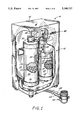
- FIG. 1 is a perspective view of the water filter unit of the present invention with the snap-type cover partially cut away for illustration purposes.
- FIG. 2 is a front plan view of the water filter unit of FIG. 1 with the water filter cartridges and snap-type cover removed.
- FIG. 3 is a top plan view of the water filter unit of FIG. 1.
- FIG. 4 is a side plan view, partially in section, of the water filter unit of FIG. 1.
- FIG. 5 is a partial cross-sectional view of the water filter unit shown in and taken along the line 5--5 in FIG. 3.
- FIG. 6 is a partial side plan view of the casing base and rear wall portion of the present invention disconnected from one another.
- FIG. 7 is a partial top plan view of the casing base and rear wall portion partially in section connected to one another.
- FIG. 8 is a plan view of one embodiment of the internal change filter indicator mechanism of the present invention.
- FIG. 9 is an exploded perspective view of the change filter indicator mechanism of FIG. 8.
- FIG. 10 is a plan view of a water filter change tool for use with the present invention.
- FIG. 11 is a side, partially sectional view of one water stream connector for use with the present invention.
- FIG. 1 a water filter unit of the present invention generally indicated by the reference numeral 10.
- the water filter unit includes a cabinet or casing 12, which includes a casing base and rear wall portion 14 and a snap-type cover 16.
- the cover 16 includes a resilient snap catch release 18, which will be described in detail with respect to FIG. 4. Any type of removable cover could be utilized.
- the rear wall portion 14 includes a pair of bracket arms 20, 22 into which are mounted a pair of water filter cartridges 24, 26.
- the water filter unit 10 includes a water stream inlet tube 28, which terminates in a coupling 30, which in turn is removably connected to an inlet end 32 of the water filter cartridge 24.
- the water filter cartridge 24 preferably includes a pair of stages including a first large particle prefilter 15 and a second reduction filter 17 for reducing chemicals, bad taste and odors from the water.
- the water filter cartridge 24 is a replaceable cartridge, Model Number TC-2 water filter produced by the assignee of the present application, Omni Corporation of Hammond, Indiana.
- the filtered water stream flows out of the water filter cartridge 24 through an outlet end 34 connected or mounted into a connector or integral manifold 36, as best described with respect to FIG. 5.
- the water stream passes through the integral manifold into an inlet end 38 of the water filter cartridge 26, also connected or mounted into the connector or integral manifold 36.
- the water filter cartridge 26 is different from the water filter cartridge 24 and also preferably is a two stage water filter, a first lead and heavy metal filter 19 and a second final water filter 21 for removing fine particles.
- the water filter cartridge 26 is a replaceable cartridge, Model Number TC-1 water filter also produced by the assignee of the present invention.
- the multiple different water filters provide a greatly enhanced water filtration over the prior art single medium filters.
- the water filter cartridges 24 and 26 are connected through the manifold 36 without valving.
- the water stream then passes out of the water filter cartridge 26 through an outlet end 40 via a removable coupling 42 into a water outlet or dispensing tube 44.
- the tubes 28 and 44 are connected to a conventional water faucet connector 46 which provides the filtered water stream on demand as will be best described with respect to FIG. 11.
- the casing 12 also preferably includes a change filter indicator 48, best described with respect to FIGS. 8 and 9.
- the rear wall portion 14, without the water filter cartridges 24, 26 and the snap-type cover 16 is best illustrated in FIG. 2.
- the bracket arms 20 and 22, preferably are formed integrally with the wall portion 14 and extend therefrom to support the water filter cartridges 24 and 26, removed from this view.
- the water stream inlet and outlet tubes 28, 44 are mounted to respective side walls 50, 52, such as by clips 53.
- the side walls 50, 52 also preferably integrally are formed with the wall portion 14 and with respective top wall portions 54, 56.
- the wall portions 50, 52, 54 and 56 provide structural strength for the rear wall portion 14, which also includes a casing base 58.
- the base 58 includes a plurality of feet 60 which provide the free standing capability of the water filter unit 10.
- the base 58 includes an aperture or opening 62, through which the inlet and outlet tubes 28, 44 extend.
- the feet 60 provide space for the tubes 28, 44, when the water filter unit is standing on a surface, not illustrated.
- the wall portion 14 also includes a pair of slotted apertures 64, 66 for the wall mounting of the water filter unit 10.
- the apertures 64, 66 can be fitted over screw or bolt heads to provide a secure wall or other surface mounting in a conventional manner.
- the wall portion 14 also includes the snap release mechanism 18 for the snap-type cover 16, best illustrated in FIGS. 2-4.
- the snap-type cover 16 includes a detent 70 recessed in a top cover portion 72.
- the snap release mechanism 68 includes an integral arm 74 biased against the top cover portion 72, with a slot or aperture 76 formed in the arm 74 to engage the detent 70.
- a pad or button 68 is depressed to release the detent 70.
- the base portion 58 includes a tab 78 formed in a front edge 80 thereof.
- the tab 78 engages a clip 82 formed in the bottom of cover 16 to secure the cover 16 to the casing 12.
- the clip 82 is attached to the cover 16 by a pair of side walls, one of which 84 is illustrated in FIG. 4.
- the manifold 36 integrally formed in the base 58 is best illustrated.
- the manifold 36 includes an inlet 86 which is formed in a closed end 88 of a threaded passageway 90.
- the water filter outlet 34 includes a male fitting 92, which is screwed into the passageway 90 to secure the water filter cartridge 24 in communication with the manifold 36.
- the manifold 36 includes a passageway or connection 94 which allows the water to flow from the inlet 86 to an outlet 96.
- the outlet 96 also is formed in an end 98 of a second threaded passageway 100 into which a male fitting 102 of the water filter inlet 38 is screwed.
- the diameter 91 of passageway 90 is not the same as the diameter 101 of passageway 100, which insures the proper water filter cartridge connection.
- FIGS. 6 and 7 best illustrate the connection of the back wall portion 14, with the preferably separate base portion 58.
- the base portion 58 includes a recessed portion 104 having a tab 106 on a rear edge 108.
- the wall portion 14 includes a portion 110 which mates with the recessed portion 104.
- the portion 110 includes an aperture 112 into which the tab 106 is secured.
- the portion 110 includes lips or channels 114 and 116, which slide over respective top and bottom edges 118, 120 formed on the portion 104.
- the portions 14 and 58 also could be formed integrally or could be adhesively secured to one another.
- the change filter indicator 48 is best shown in FIGS. 8 and 9.
- the change filter indicator 48 could be formed in numerous ways, however, for example purposes, the change filter indicator 48 includes three separate discs 122, 124 and 126. Each disc 122, 124, and 126 is mounted for rotation onto a post 128, formed or secured on the inside of the cover 16. The discs 122, 124 and 126 can be secured on the post 128 by a removable clip 130.
- the change filter indicator 48 includes two apertures 132 and 134 through which the months and years can be exhibited for the two filters. Preferably, the aperture 134 displays the month in which a first one of the water filter cartridges should be changed.
- the months of the year are printed on the outer edge of the disc 126, which is rotated to the proper month when the first water filter cartridge is installed or changed.
- the month and year for the second filter cartridge change are displayed through the aperture 132.
- the years are printed on the outer edge of the disc 124 and are displayed through one of a plurality of holes 136 (only one of which is illustrated) in the disc 126.
- the months are printed on the outer edge of the disc 122 and are displayed through one of a plurality of holes 138 (only one of which is illustrated) in the disc 124 and through the same hole 136 (if elongated) or a separate hole 140 in the disc 126.
- the water faucet connector 46 is best illustrated.
- the water faucet connector 46 can be any type of water faucet connector, but for example purposes, the water faucet connector 46 includes a fitting 142 which is screwed onto a standard water faucet. If the water faucet connector 10 is not being utilized, the water flows through a passageway 144, past a connecting pin 146 and out a passageway 148.
- the connecting pin 146 is pulled to block the passageway 148 and the water flows into a passageway 150 and then into the water inlet tube 28.
- the filtered water then is discharged through the water outlet tube 44 through a nozzle 152.
- a water filter cartridge change tool 154 is illustrated, secured when not in use between the brackets 20 and 22 in a slot 156 (see FIG. 2).
- the change tool 154 includes a handle 158 and a pair of outlet arms 160 and 162.
- Each arm 160, 162 has a respective slot 164, 166 formed therein, which slots 164, 166 mate to respective flanges 168, 170 on each of the couplings 30 and 42 (see FIG. 2).
- the change tool 154 preferably is formed of plastic and has an open mouth 172 so that the change tool 154 easily can be utilized with the couplings 30 and 42.
Landscapes
- Life Sciences & Earth Sciences (AREA)
- Hydrology & Water Resources (AREA)
- Engineering & Computer Science (AREA)
- Environmental & Geological Engineering (AREA)
- Water Supply & Treatment (AREA)
- Chemical & Material Sciences (AREA)
- Organic Chemistry (AREA)
- Water Treatment By Sorption (AREA)
Abstract
Description
Claims (8)
Priority Applications (1)
| Application Number | Priority Date | Filing Date | Title |
|---|---|---|---|
| US07/849,782 US5188727A (en) | 1990-07-18 | 1992-03-10 | Water filter unit |
Applications Claiming Priority (2)
| Application Number | Priority Date | Filing Date | Title |
|---|---|---|---|
| US55507690A | 1990-07-18 | 1990-07-18 | |
| US07/849,782 US5188727A (en) | 1990-07-18 | 1992-03-10 | Water filter unit |
Related Parent Applications (1)
| Application Number | Title | Priority Date | Filing Date |
|---|---|---|---|
| US55507690A Continuation | 1990-07-18 | 1990-07-18 |
Publications (1)
| Publication Number | Publication Date |
|---|---|
| US5188727A true US5188727A (en) | 1993-02-23 |
Family
ID=27070784
Family Applications (1)
| Application Number | Title | Priority Date | Filing Date |
|---|---|---|---|
| US07/849,782 Expired - Fee Related US5188727A (en) | 1990-07-18 | 1992-03-10 | Water filter unit |
Country Status (1)
| Country | Link |
|---|---|
| US (1) | US5188727A (en) |
Cited By (35)
| Publication number | Priority date | Publication date | Assignee | Title |
|---|---|---|---|---|
| US5397468A (en) * | 1992-09-24 | 1995-03-14 | Barnstead Thermolyne | Water purifier cartridge coupling |
| GB2292696A (en) * | 1994-09-01 | 1996-03-06 | Malcolm Graham Goodson | Method and apparatus for water treatment |
| US5645719A (en) * | 1995-07-29 | 1997-07-08 | Samsung Electronics Co., Ltd. | Filter clamping device for water purifiers |
| US5662792A (en) * | 1994-11-14 | 1997-09-02 | Samsung Electronics Co., Ltd. | Water purifier having reinforcement preventing deformation of a tank-supporting wall |
| CN1036976C (en) * | 1994-11-14 | 1998-01-14 | 三星电子株式会社 | Overflowed control device for water clarifier |
| CN1037750C (en) * | 1994-11-14 | 1998-03-18 | 三星电子株式会社 | Water purifier |
| WO1998013302A1 (en) * | 1996-09-24 | 1998-04-02 | Ferguson George E | Modular multi-stage water filter apparatus |
| US5766282A (en) * | 1995-01-05 | 1998-06-16 | Bin; Louis | Filtering bags with bag filter labels |
| US5833850A (en) * | 1997-08-15 | 1998-11-10 | Liu; Hsin Fa | Water filter |
| US6001249A (en) * | 1997-11-06 | 1999-12-14 | Dart Industries Inc. | Multi-stage water filter system |
| US6071405A (en) * | 1996-05-14 | 2000-06-06 | Charmilles, Zubehoer, Ersatzteile, Vertriebsgesellschaft Mbh | Apparatus for desalting and conditioning water |
| US6139739A (en) * | 1998-10-08 | 2000-10-31 | Cuno Incorporated | Composite filter element |
| FR2799662A1 (en) * | 1999-10-19 | 2001-04-20 | Moulinex Sa | REMOVABLE CARTRIDGE FOR WATER TREATMENT AND INFUSION MACHINE COMPRISING SUCH A CARTRIDGE |
| US6306290B1 (en) * | 2000-06-26 | 2001-10-23 | Patrick J. Rolfes | Water filter replacement indicator |
| US6355177B2 (en) | 2000-03-07 | 2002-03-12 | Maytag Corporation | Water filter cartridge replacement system for a refrigerator |
| US20040055946A1 (en) * | 2002-09-20 | 2004-03-25 | Sid Harvey Industries, Inc. | Dual filtration system |
| US20040129617A1 (en) * | 2001-08-23 | 2004-07-08 | Pur Water Purification Products, Inc. | Water filter device |
| US20050279689A1 (en) * | 2004-04-02 | 2005-12-22 | Tana Industries (1991) Ltd. | Water dispenser and filter cartridge for use therein |
| EP1936306A2 (en) * | 2006-12-19 | 2008-06-25 | Whirlpool Corporation | Water filter removal and installation tool |
| US20080156711A1 (en) * | 2006-12-29 | 2008-07-03 | Vitan Craig R | Water filter assembly and filter cartridge for use therewith |
| US20080230454A1 (en) * | 2007-03-23 | 2008-09-25 | Nibler David B | Pool filter |
| US20090090665A1 (en) * | 2007-10-05 | 2009-04-09 | Nibler David B | Methods and Apparatus for a Pool Treatment and Water System |
| US20090218292A1 (en) * | 2001-08-23 | 2009-09-03 | Michael Donovan Mitchell | Methods of treating water |
| US20090230061A1 (en) * | 2001-08-23 | 2009-09-17 | Michael Donovan Mitchell | Methods for treating water |
| US7740766B2 (en) | 2001-08-23 | 2010-06-22 | The Procter & Gamble Company | Methods for treating water |
| US7794591B2 (en) | 2007-03-23 | 2010-09-14 | Zodiac Pool Systems, Inc. | Pool filter |
| US20100270217A1 (en) * | 2006-10-12 | 2010-10-28 | Burrows Bruce D | Drainless reverse osmosis water purification system |
| US20100278587A1 (en) * | 2009-04-29 | 2010-11-04 | Zodiac Pool Systems, Inc. | Retainer Band for Use in Fluid-Handling Vessels |
| US7922008B2 (en) | 2001-08-23 | 2011-04-12 | The Procter & Gamble Company | Water filter materials and water filters containing a mixture of microporous and mesoporous carbon particles |
| US8097067B2 (en) | 2009-05-06 | 2012-01-17 | 3M Innovative Properties Company | Runtime sensor for small forced air handling units |
| US9371245B2 (en) | 2006-10-12 | 2016-06-21 | Bruce D. Burrows | Drainless reverse osmosis water purification system |
| RU2617775C1 (en) * | 2016-05-20 | 2017-04-26 | Закрытое Акционерное Общество "Аквафор Продакшн" (Зао "Аквафор Продакшн") | Filtering module of liquid purification device |
| US9919933B2 (en) | 2013-12-18 | 2018-03-20 | Ds Services Of America, Inc. | Water purification system with active vibration |
| US10240324B2 (en) * | 2014-10-31 | 2019-03-26 | Andrey Yurievich Yazykov | Water-supply device |
| US20210179448A1 (en) * | 2016-04-22 | 2021-06-17 | Pall Corporation | Water processing device |
Citations (11)
| Publication number | Priority date | Publication date | Assignee | Title |
|---|---|---|---|---|
| US452671A (en) * | 1891-05-19 | Desk-cabinet | ||
| US1253562A (en) * | 1917-02-16 | 1918-01-15 | Julius Appelbaum | Calendar. |
| US3653514A (en) * | 1970-12-07 | 1972-04-04 | King Holler International | Water softener |
| US3802563A (en) * | 1970-12-23 | 1974-04-09 | Matsushita Electric Ind Co Ltd | Water purifying device |
| US4138337A (en) * | 1977-11-17 | 1979-02-06 | Smith Robert G | Filter cartridge |
| US4681677A (en) * | 1978-02-17 | 1987-07-21 | Olin Corporation | Water processor having automatic shutoff and bypass means |
| US4683054A (en) * | 1986-06-23 | 1987-07-28 | Turnbull William E | Appliance for purifying water |
| US4713175A (en) * | 1986-08-05 | 1987-12-15 | Nimbus Water Systems, Inc. | Water purifier comprising stages mounted side-by-side to unitary header |
| US4759844A (en) * | 1986-03-21 | 1988-07-26 | Aquathin Corp. | Portable water purification system |
| US4895648A (en) * | 1988-04-30 | 1990-01-23 | Brita Wasser-Filter-Systeme Gmbh | Filter cover for a purification insert in a water treatment device with a hollow tube |
| US4909931A (en) * | 1987-12-17 | 1990-03-20 | Tana - Netiv Halamed-He Industries | Water-purifier device |
-
1992
- 1992-03-10 US US07/849,782 patent/US5188727A/en not_active Expired - Fee Related
Patent Citations (11)
| Publication number | Priority date | Publication date | Assignee | Title |
|---|---|---|---|---|
| US452671A (en) * | 1891-05-19 | Desk-cabinet | ||
| US1253562A (en) * | 1917-02-16 | 1918-01-15 | Julius Appelbaum | Calendar. |
| US3653514A (en) * | 1970-12-07 | 1972-04-04 | King Holler International | Water softener |
| US3802563A (en) * | 1970-12-23 | 1974-04-09 | Matsushita Electric Ind Co Ltd | Water purifying device |
| US4138337A (en) * | 1977-11-17 | 1979-02-06 | Smith Robert G | Filter cartridge |
| US4681677A (en) * | 1978-02-17 | 1987-07-21 | Olin Corporation | Water processor having automatic shutoff and bypass means |
| US4759844A (en) * | 1986-03-21 | 1988-07-26 | Aquathin Corp. | Portable water purification system |
| US4683054A (en) * | 1986-06-23 | 1987-07-28 | Turnbull William E | Appliance for purifying water |
| US4713175A (en) * | 1986-08-05 | 1987-12-15 | Nimbus Water Systems, Inc. | Water purifier comprising stages mounted side-by-side to unitary header |
| US4909931A (en) * | 1987-12-17 | 1990-03-20 | Tana - Netiv Halamed-He Industries | Water-purifier device |
| US4895648A (en) * | 1988-04-30 | 1990-01-23 | Brita Wasser-Filter-Systeme Gmbh | Filter cover for a purification insert in a water treatment device with a hollow tube |
Cited By (65)
| Publication number | Priority date | Publication date | Assignee | Title |
|---|---|---|---|---|
| US5397468A (en) * | 1992-09-24 | 1995-03-14 | Barnstead Thermolyne | Water purifier cartridge coupling |
| GB2292696A (en) * | 1994-09-01 | 1996-03-06 | Malcolm Graham Goodson | Method and apparatus for water treatment |
| GB2292696B (en) * | 1994-09-01 | 1998-06-10 | Malcolm Graham Goodson | Method and apparatus for water treatment |
| US5662792A (en) * | 1994-11-14 | 1997-09-02 | Samsung Electronics Co., Ltd. | Water purifier having reinforcement preventing deformation of a tank-supporting wall |
| CN1036976C (en) * | 1994-11-14 | 1998-01-14 | 三星电子株式会社 | Overflowed control device for water clarifier |
| CN1037749C (en) * | 1994-11-14 | 1998-03-18 | 三星电子株式会社 | Water purification device |
| CN1037750C (en) * | 1994-11-14 | 1998-03-18 | 三星电子株式会社 | Water purifier |
| US5766282A (en) * | 1995-01-05 | 1998-06-16 | Bin; Louis | Filtering bags with bag filter labels |
| US5645719A (en) * | 1995-07-29 | 1997-07-08 | Samsung Electronics Co., Ltd. | Filter clamping device for water purifiers |
| US6071405A (en) * | 1996-05-14 | 2000-06-06 | Charmilles, Zubehoer, Ersatzteile, Vertriebsgesellschaft Mbh | Apparatus for desalting and conditioning water |
| WO1998013302A1 (en) * | 1996-09-24 | 1998-04-02 | Ferguson George E | Modular multi-stage water filter apparatus |
| US6203697B1 (en) | 1996-09-24 | 2001-03-20 | George E. Ferguson | Modular multi-stage water filter apparatus |
| US5833850A (en) * | 1997-08-15 | 1998-11-10 | Liu; Hsin Fa | Water filter |
| US6001249A (en) * | 1997-11-06 | 1999-12-14 | Dart Industries Inc. | Multi-stage water filter system |
| AU752517B2 (en) * | 1997-11-06 | 2002-09-19 | Dart Industries Inc. | Multi-stage water filter system |
| US6139739A (en) * | 1998-10-08 | 2000-10-31 | Cuno Incorporated | Composite filter element |
| US6432233B1 (en) | 1998-10-08 | 2002-08-13 | Cuno, Inc. | Composite filter element |
| US20040129624A1 (en) * | 1998-10-08 | 2004-07-08 | Hamlin Thomas J. | Composite filter element |
| FR2799662A1 (en) * | 1999-10-19 | 2001-04-20 | Moulinex Sa | REMOVABLE CARTRIDGE FOR WATER TREATMENT AND INFUSION MACHINE COMPRISING SUCH A CARTRIDGE |
| EP1093747A3 (en) * | 1999-10-19 | 2002-05-22 | Moulinex S.A. | Removable water treatment cartridge and beverage brewing machine containing such a cartridge |
| US6355177B2 (en) | 2000-03-07 | 2002-03-12 | Maytag Corporation | Water filter cartridge replacement system for a refrigerator |
| US6306290B1 (en) * | 2000-06-26 | 2001-10-23 | Patrick J. Rolfes | Water filter replacement indicator |
| US20090230061A1 (en) * | 2001-08-23 | 2009-09-17 | Michael Donovan Mitchell | Methods for treating water |
| US7850859B2 (en) | 2001-08-23 | 2010-12-14 | The Procter & Gamble Company | Water treating methods |
| US8119012B2 (en) | 2001-08-23 | 2012-02-21 | The Procter & Gamble Company | Water filter materials and water filters containing a mixture of microporous and mesoporous carbon particles |
| US20040129617A1 (en) * | 2001-08-23 | 2004-07-08 | Pur Water Purification Products, Inc. | Water filter device |
| US20110155661A1 (en) * | 2001-08-23 | 2011-06-30 | Jeannine Rebecca Bahm | Water filter materials and water filters containing a mixture of microporous and mesoporous carbon particles |
| US7922008B2 (en) | 2001-08-23 | 2011-04-12 | The Procter & Gamble Company | Water filter materials and water filters containing a mixture of microporous and mesoporous carbon particles |
| US7749394B2 (en) | 2001-08-23 | 2010-07-06 | The Procter & Gamble Company | Methods of treating water |
| US7740766B2 (en) | 2001-08-23 | 2010-06-22 | The Procter & Gamble Company | Methods for treating water |
| US7740765B2 (en) | 2001-08-23 | 2010-06-22 | The Procter & Gamble Company | Methods for treating water |
| US20090218292A1 (en) * | 2001-08-23 | 2009-09-03 | Michael Donovan Mitchell | Methods of treating water |
| US20040055946A1 (en) * | 2002-09-20 | 2004-03-25 | Sid Harvey Industries, Inc. | Dual filtration system |
| US20080202996A1 (en) * | 2004-04-02 | 2008-08-28 | Tana Industries (1991) Ltd. | Water dispenser and filter cartridge for use therein |
| US7645381B2 (en) * | 2004-04-02 | 2010-01-12 | Tana Industries (1991) Ltd. | Water dispenser and filter cartridge for use therein |
| US7703382B2 (en) | 2004-04-02 | 2010-04-27 | Tana Industries (1991) Ltd. | Water dispenser and filter cartridge for use therein |
| US20090071890A1 (en) * | 2004-04-02 | 2009-03-19 | Tana Industries (1991) Ltd. | Water dispenser and filter cartridge for use therein |
| US7470364B2 (en) * | 2004-04-02 | 2008-12-30 | Tanna Industries (1991) Ltd. | Water dispenser and filter cartridge for use therein |
| US20100163470A1 (en) * | 2004-04-02 | 2010-07-01 | Tana Industries (1991) Ltd. | Water dispenser and filter cartridge for use therein |
| US20050279689A1 (en) * | 2004-04-02 | 2005-12-22 | Tana Industries (1991) Ltd. | Water dispenser and filter cartridge for use therein |
| US7987769B2 (en) * | 2004-04-02 | 2011-08-02 | Strauss Water Ltd. | Water dispenser and filter cartridge for use therein |
| US20100270217A1 (en) * | 2006-10-12 | 2010-10-28 | Burrows Bruce D | Drainless reverse osmosis water purification system |
| US10196292B2 (en) | 2006-10-12 | 2019-02-05 | Ds Services Of America, Inc. | Drainless reverse osmosis water purification system |
| US9371245B2 (en) | 2006-10-12 | 2016-06-21 | Bruce D. Burrows | Drainless reverse osmosis water purification system |
| US8298420B2 (en) * | 2006-10-12 | 2012-10-30 | Burrows Bruce D | Drainless reverse osmosis water purification system |
| EP1936306A3 (en) * | 2006-12-19 | 2014-01-01 | Whirlpool Corporation | Water filter removal and installation tool |
| EP1936306A2 (en) * | 2006-12-19 | 2008-06-25 | Whirlpool Corporation | Water filter removal and installation tool |
| US20080156711A1 (en) * | 2006-12-29 | 2008-07-03 | Vitan Craig R | Water filter assembly and filter cartridge for use therewith |
| US8137545B2 (en) | 2007-03-23 | 2012-03-20 | Zodiac Pool Systems, Inc. | Pool filter |
| US7815796B2 (en) | 2007-03-23 | 2010-10-19 | Zodiac Pool Systems, Inc. | Pool filter |
| US7794591B2 (en) | 2007-03-23 | 2010-09-14 | Zodiac Pool Systems, Inc. | Pool filter |
| US20080230454A1 (en) * | 2007-03-23 | 2008-09-25 | Nibler David B | Pool filter |
| US8173011B2 (en) | 2007-10-05 | 2012-05-08 | Zodiac Pool Systems, Inc. | Methods and apparatus for a pool treatment and water system |
| US20110226682A1 (en) * | 2007-10-05 | 2011-09-22 | Zodiac Pool Systems, Inc. | Methods and Apparatus for a Pool Treatment and Water System |
| US7951293B2 (en) | 2007-10-05 | 2011-05-31 | Zodiac Pool Systems, Inc. | Methods and apparatus for a pool treatment and water system |
| US20090090665A1 (en) * | 2007-10-05 | 2009-04-09 | Nibler David B | Methods and Apparatus for a Pool Treatment and Water System |
| US8516661B2 (en) | 2009-04-29 | 2013-08-27 | Zodiac Pool Systems, Inc. | Retainer band for use in fluid-handling vessels |
| US20100278587A1 (en) * | 2009-04-29 | 2010-11-04 | Zodiac Pool Systems, Inc. | Retainer Band for Use in Fluid-Handling Vessels |
| US8097067B2 (en) | 2009-05-06 | 2012-01-17 | 3M Innovative Properties Company | Runtime sensor for small forced air handling units |
| US9919933B2 (en) | 2013-12-18 | 2018-03-20 | Ds Services Of America, Inc. | Water purification system with active vibration |
| US10240324B2 (en) * | 2014-10-31 | 2019-03-26 | Andrey Yurievich Yazykov | Water-supply device |
| US20210179448A1 (en) * | 2016-04-22 | 2021-06-17 | Pall Corporation | Water processing device |
| RU2617775C1 (en) * | 2016-05-20 | 2017-04-26 | Закрытое Акционерное Общество "Аквафор Продакшн" (Зао "Аквафор Продакшн") | Filtering module of liquid purification device |
| WO2017200423A1 (en) * | 2016-05-20 | 2017-11-23 | Закрытое Акционерное Общество "Аквафор Продакшн" (Зао "Аквафор Продакшн") | Filter module for a liquid purification device |
| US11173428B2 (en) | 2016-05-20 | 2021-11-16 | Electrophor, Inc. | Filter cartridge of water purification system |
Similar Documents
| Publication | Publication Date | Title |
|---|---|---|
| US5188727A (en) | Water filter unit | |
| US5725025A (en) | Fluid filtration system with quick-release fluid hose fitting | |
| US6203697B1 (en) | Modular multi-stage water filter apparatus | |
| KR100358713B1 (en) | Water treatment equipment | |
| US20060037893A1 (en) | Single-use long-life faucet-mounted water filtration devices | |
| US5192427A (en) | Shower filters and accessories | |
| US5122272A (en) | Drinking water supply container having a removably mounted filter device | |
| US5167819A (en) | Canteen having a removably mounted filter device | |
| US5152464A (en) | Shower filter assembly | |
| US4368123A (en) | Regenerative counter top water conditioner | |
| EP0631020B2 (en) | Aerator for liquids | |
| US3950251A (en) | Filter with quick-connect coupling | |
| US5277805A (en) | Rechargeable water filter | |
| JP2002500944A (en) | Water filter with hydrant | |
| WO1998013302A9 (en) | Modular multi-stage water filter apparatus | |
| CA2172594A1 (en) | Strainer | |
| JP4216602B2 (en) | Water outlet with detachable laminar flow cartridge | |
| US20060108267A1 (en) | Single-use long-life faucet-mounted water filtration devices | |
| US3717253A (en) | Adjustable bracket and filter for various sizes of home aquariums | |
| US20100089472A1 (en) | Faucet with Integral Filter and Method of Installation | |
| US20040074992A1 (en) | Tamper-resistant flow modifier assembly | |
| US20050092661A1 (en) | Single-use long-life faucet-mounted water filtration devices | |
| USD541374S1 (en) | Faucet mounted water filter | |
| CA2027953A1 (en) | Water filter unit | |
| US6312595B1 (en) | Water filtering system |
Legal Events
| Date | Code | Title | Description |
|---|---|---|---|
| FEPP | Fee payment procedure |
Free format text: PAYOR NUMBER ASSIGNED (ORIGINAL EVENT CODE: ASPN); ENTITY STATUS OF PATENT OWNER: LARGE ENTITY |
|
| FPAY | Fee payment |
Year of fee payment: 4 |
|
| FEPP | Fee payment procedure |
Free format text: PAT HLDR NO LONGER CLAIMS SMALL ENT STAT AS INDIV INVENTOR (ORIGINAL EVENT CODE: LSM1); ENTITY STATUS OF PATENT OWNER: LARGE ENTITY |
|
| REFU | Refund |
Free format text: REFUND - PAYMENT OF MAINTENANCE FEE, 8TH YR, SMALL ENTITY (ORIGINAL EVENT CODE: R284); ENTITY STATUS OF PATENT OWNER: LARGE ENTITY |
|
| FPAY | Fee payment |
Year of fee payment: 8 |
|
| AS | Assignment |
Owner name: STA-RITE INDUSTRIES, INC., WISCONSIN Free format text: ASSIGNMENT OF ASSIGNORS INTEREST;ASSIGNOR:OMNI CORPORATION;REEL/FRAME:011442/0605 Effective date: 19990630 |
|
| REMI | Maintenance fee reminder mailed | ||
| LAPS | Lapse for failure to pay maintenance fees | ||
| STCH | Information on status: patent discontinuation |
Free format text: PATENT EXPIRED DUE TO NONPAYMENT OF MAINTENANCE FEES UNDER 37 CFR 1.362 |
|
| FP | Lapsed due to failure to pay maintenance fee |
Effective date: 20050223 |