US5192295A - Angioplasty dilatation balloon catheter/guidewire system - Google Patents
Angioplasty dilatation balloon catheter/guidewire system Download PDFInfo
- Publication number
- US5192295A US5192295A US07/540,957 US54095790A US5192295A US 5192295 A US5192295 A US 5192295A US 54095790 A US54095790 A US 54095790A US 5192295 A US5192295 A US 5192295A
- Authority
- US
- United States
- Prior art keywords
- tubular
- guidewire
- submember
- catheter
- balloon
- Prior art date
- Legal status (The legal status is an assumption and is not a legal conclusion. Google has not performed a legal analysis and makes no representation as to the accuracy of the status listed.)
- Expired - Lifetime
Links
Images


Classifications
-
- A—HUMAN NECESSITIES
- A61—MEDICAL OR VETERINARY SCIENCE; HYGIENE
- A61M—DEVICES FOR INTRODUCING MEDIA INTO, OR ONTO, THE BODY; DEVICES FOR TRANSDUCING BODY MEDIA OR FOR TAKING MEDIA FROM THE BODY; DEVICES FOR PRODUCING OR ENDING SLEEP OR STUPOR
- A61M25/00—Catheters; Hollow probes
- A61M25/10—Balloon catheters
- A61M25/104—Balloon catheters used for angioplasty
-
- A—HUMAN NECESSITIES
- A61—MEDICAL OR VETERINARY SCIENCE; HYGIENE
- A61M—DEVICES FOR INTRODUCING MEDIA INTO, OR ONTO, THE BODY; DEVICES FOR TRANSDUCING BODY MEDIA OR FOR TAKING MEDIA FROM THE BODY; DEVICES FOR PRODUCING OR ENDING SLEEP OR STUPOR
- A61M25/00—Catheters; Hollow probes
- A61M25/01—Introducing, guiding, advancing, emplacing or holding catheters
- A61M25/09—Guide wires
-
- A—HUMAN NECESSITIES
- A61—MEDICAL OR VETERINARY SCIENCE; HYGIENE
- A61M—DEVICES FOR INTRODUCING MEDIA INTO, OR ONTO, THE BODY; DEVICES FOR TRANSDUCING BODY MEDIA OR FOR TAKING MEDIA FROM THE BODY; DEVICES FOR PRODUCING OR ENDING SLEEP OR STUPOR
- A61M25/00—Catheters; Hollow probes
- A61M25/01—Introducing, guiding, advancing, emplacing or holding catheters
- A61M2025/0183—Rapid exchange or monorail catheters
-
- A—HUMAN NECESSITIES
- A61—MEDICAL OR VETERINARY SCIENCE; HYGIENE
- A61M—DEVICES FOR INTRODUCING MEDIA INTO, OR ONTO, THE BODY; DEVICES FOR TRANSDUCING BODY MEDIA OR FOR TAKING MEDIA FROM THE BODY; DEVICES FOR PRODUCING OR ENDING SLEEP OR STUPOR
- A61M25/00—Catheters; Hollow probes
- A61M25/01—Introducing, guiding, advancing, emplacing or holding catheters
- A61M25/09—Guide wires
- A61M2025/09175—Guide wires having specific characteristics at the distal tip
-
- A—HUMAN NECESSITIES
- A61—MEDICAL OR VETERINARY SCIENCE; HYGIENE
- A61M—DEVICES FOR INTRODUCING MEDIA INTO, OR ONTO, THE BODY; DEVICES FOR TRANSDUCING BODY MEDIA OR FOR TAKING MEDIA FROM THE BODY; DEVICES FOR PRODUCING OR ENDING SLEEP OR STUPOR
- A61M25/00—Catheters; Hollow probes
- A61M25/10—Balloon catheters
- A61M2025/1043—Balloon catheters with special features or adapted for special applications
- A61M2025/1063—Balloon catheters with special features or adapted for special applications having only one lumen used for guide wire and inflation, e.g. to minimise the diameter
-
- A—HUMAN NECESSITIES
- A61—MEDICAL OR VETERINARY SCIENCE; HYGIENE
- A61M—DEVICES FOR INTRODUCING MEDIA INTO, OR ONTO, THE BODY; DEVICES FOR TRANSDUCING BODY MEDIA OR FOR TAKING MEDIA FROM THE BODY; DEVICES FOR PRODUCING OR ENDING SLEEP OR STUPOR
- A61M25/00—Catheters; Hollow probes
- A61M25/10—Balloon catheters
- A61M2025/1043—Balloon catheters with special features or adapted for special applications
- A61M2025/1079—Balloon catheters with special features or adapted for special applications having radio-opaque markers in the region of the balloon
-
- A—HUMAN NECESSITIES
- A61—MEDICAL OR VETERINARY SCIENCE; HYGIENE
- A61M—DEVICES FOR INTRODUCING MEDIA INTO, OR ONTO, THE BODY; DEVICES FOR TRANSDUCING BODY MEDIA OR FOR TAKING MEDIA FROM THE BODY; DEVICES FOR PRODUCING OR ENDING SLEEP OR STUPOR
- A61M25/00—Catheters; Hollow probes
- A61M25/10—Balloon catheters
- A61M2025/1043—Balloon catheters with special features or adapted for special applications
- A61M2025/1093—Balloon catheters with special features or adapted for special applications having particular tip characteristics
Definitions
- This invention relates to catheters and in particular to guidewire-directed dilation balloon catheters, for use in the performance of percutaneous transluminal peripheral and coronary angioplasty.
- Dr. Andreas Gruentzig first used a balloon-tipped flexible catheter to percutaneously dilate a region of stenosis within the coronary artery of a patient with atherosclerotic heart disease. Since that time, the incidence of percutaneous transluminal coronary angioplasty has increased exponentially. Over the course of the past eight to ten years, the performance of this procedure has become routine within many major medical centers throughout the world. With the advent of improved technology and operator skill, the indications for this procedure have increased substantially.
- U.S. Pat. No. 4,195,637 describes the original catheter conceived by Dr. Gruentzig. By current standards, the design of this device affords limited directional control. Use of this device was largely abandoned in the early 1980's following the introduction of "over-the-wire" catheters.
- U.S. Pat. No. 4,299,226, describes an over-the-wire catheter. Over-the-wire catheters have remained the most popular angioplasty catheters to date, despite the advent of a variety of more recently developed "non-over-the-wire" catheter systems. The popularity of over-the-wire catheters stems largely from the fact that these catheters remain the safest and, with minor exception, the most steerable catheters among the prior art.
- the crossing profile of a balloon catheter system is defined as the maximal profile of the deflated balloon component of the system.
- over-the-wire devices have substantially larger crossing profiles.
- these catheters create more resistance during manipulation within the confines of critical stenoses, require more force to install across lesions and cause more intravascular trauma during this process compared to the more recently developed, lower profile non-over-the-wire devices.
- the factors that influence the magnitude of the crossing profile of an over-the-wire device of the prior art include: (1) the inflated profile of the balloon component, (2) the thickness of the walls of the balloon component and (3) the profile of the inner member that extends through the confines of the balloon component.
- the first factor, the inflated profile of the balloon impacts the crossing profile of over-the-wire angioplasty dilatation balloon catheters because the materials most suitable for use in the construction of the balloon components of angioplasty catheters are relatively noncompliant. Further progress in reducing the crossing profile of an over-the-wire system of the prior art is constrained by the need to maintain the inflated balloon profile of the device within the therapeutic range (i.e., 1.5-4.0 mm for coronary catheters and 4-10 mm for peripheral vascular catheters).
- the second factor also impacts the crossing profile of over-the-wire devices of the prior art.
- the crossing profile of over-the-wire catheters has been reduced by decreasing the thickness of the walls of the balloon component.
- the wall thickness of the balloon component must remain within a range that confers satisfactory pressure tolerance and balloon durability.
- the third factor influencing the crossing profile is the profile of the inner member of the balloon.
- the luminal profile of the inner member of the balloon component of prior art over-the-wire systems must exceed the maximal profile of the guidewire mandrel contained within the system to enable bidirectional separation of the catheter component from the guidewire component of these systems. Separability of the guidewire component form the catheter component constitutes one of the fundamental functional advantages of this class of catheters. This feature affords the opportunity to accomplish a catheter exchange without the need to sacrifice intraluminal access during this process.
- the factors that influence the profile of the balloon component inner member of prior art devices include: (a) the maximal profile of the guidewire mandrel contained within the device; (b) the magnitude of the catheter-guidewire clearance within the vicinity of the balloon component of the catheter; and (c) the thickness of the walls of the balloon component inner member.
- the maximal (i.e. proximal) profile of the guidewire mandrels contained within these devices has been reduced with the aim to reduce the crossing profile of the composite device.
- This approach reduces both the "trackability" and the directional control or "steerability" of these systems.
- the trackability of a catheter is the facility with which a catheter can be advanced over a guidewire.
- the magnitude of the catheter-guidewire clearance within the vicinity of the balloon also impacts the profile of the balloon component inner member and hence the crossing profile of the composite device. Reducing the magnitude of the catheter-guidewire clearance reduces the directional control of the device.
- the directional control of an over-the-wire system of the prior art varies directly as a function of the magnitude of rotational torque that can be delivered to the distal aspect of the guidewire.
- the efficiency with which this rotational torque can be transmitted within the confines of an over-the-wire system of the prior art varies, in part, with the magnitude of the catheter/guidewire clearance. Further progress in reducing the crossing profile of an over-the-wire device of the prior art is constrained by the need to maintain the magnitude of the catheter-guidewire clearance within a range that permits satisfactory guidewire-mediated torque delivery and hence satisfactory directional control.
- the thickness of the walls of the balloon component inner member also impacts the profile of the inner member and hence the crossing profile of the composite device.
- the inner member confers column strength (i.e., resistance to coaxial compression) to the catheter.
- the magnitude of column strength conferred by the inner member varies directly with the thickness of the walls of the inner member (provided that comparable materials are used in the construction of the respective inner members).
- the column strength of a particular device profoundly influences the feasibility with which the device can be negotiated within the confines of critically stenotic lesions.
- Prior art catheters with thinner balloon component inner member walls, the catheters generally suffer from reduced pushability or column strength. Any further reduction in the crossing profile of conventional over-the-wire devices is constrained by the need to maintain the thickness of the walls of the inner member within a range that confers satisfactory column strength to the composite system.
- Each of these systems are easier to prepare, and more convenient to use relative to over-the-wire systems because they contain pre-installed guidewires.
- Each of these devices can be advanced within the confines of critical lesions with greater facility relative to over-the-wire devices of the prior art because they have lower crossing profiles.
- Intraoperative angiography is commonly performed following balloon dilatation, during the course of an angioplasty procedure, to assess the impact of the procedure on the configuration of the lesion requiring dilatation.
- Semi-movable and over-the-wire devices readily permit intraoperative angiography.
- the catheter components of these systems can be withdrawn over the respective guidewire components, to enable the performance of intraoperative angiography, without sacrificing intraluminal guidewire access during this process.
- the balloon components of these systems can be readvanced over the respective guidewire components across the confines of the respective stenoses and re-inflated.
- the use of these devices obligates sacrificing intraluminal access during the performance of intraoperative angiography. Hence, their use exposes the patient to the added risk associated with renegotiation of the lesion, when subsequent dilatation is required.
- the angioplasty balloon dilatation catheter of our invention provides numerous advantages relative to the prior art.
- the invention permits the construction of a highly steerable and entirely separable guidewire-directed dilatation balloon catheter system with a lower crossing profile relative to prior art over-the-wire catheters of commensurate inflated balloon size that accommodate guidewires of commensurate proximal profile.
- our invention permits the construction of a device with a crossing profile that is comparable to state-of-the-art fixed-wire and balloon-on-a-wire devices of commensurate inflated balloon size. This is accomplished by: (1) constructing the balloon component inner member with a particularly low profile, and (2) disposing the balloon component inner member over a relatively low profile segment of a guidewire of non-uniform profile.
- the luminal dimensions of the balloon component inner member of the catheter component of our system is less than the profile of the proximal and distal aspects of the guidewire contained within the system.
- the lower crossing profile of our device enables it to be introduced across the confines of critical stenoses with less force and with less potential for catheter induced trauma relative to prior art over-the-wire systems of commensurate inflated balloon size that accommodate guidewires of commensurate proximal profile.
- the invention permits the construction of a low profile guidewire-directed dilatation balloon catheter that affords excellent directional control. This is accomplished by disposing within the device a guidewire containing a tapered mandrel of relatively large proximal profile.
- Our invention provides unimpaired rotational and limited unimpaired coaxial guidewire mobility.
- the extent to which the guidewire can be advanced and/or retracted freely within the confines of the catheter is a function of the configuration of the guidewire. Specifically, the extent to which the guidewire can be advanced and retracted is determined by the length of the guidewire segment contained by the balloon component inner member, which segment is lower in profile than the luminal dimensions of the balloon component inner member.
- Advancing or retracting the guidewire beyond this region brings the opposing surfaces of the guidewire and catheter into direct contact, and thereby partially impairs the relative mobility of these two system components.
- the ability to advance and retract the guidewire component relative to the catheter component enhances the reach and cross potential of the device and facilitates the performance of intraoperative angiography.
- the catheter/guidewire system of our invention permits complete separation of the catheter component from the guidewire component of the system. This is accomplished by constructing the balloon component inner member of the device in a manner that enables it to expand or unfold radially and thus accommodate the changes in profile of the guidewire as the guidewire is advanced or withdrawn therethrough.
- the inner member is designed to accommodate these changes in profile with relative ease.
- the catheter component of the system of our design can be withdrawn over the guidewire component and completely separated therefrom, enabling the performance of a catheter exchange without sacrificing intraluminal access.
- the guidewire component can be withdrawn through the confines of the catheter component and readvanced therethrough, enabling the performance of a guidewire exchange without removing the catheter from the vasculature.
- a radially expandable inner member in combination with a guidewire of non-uniform profile enables the construction of an ultra-low profile, highly steerable, entirely separable, guidewire-directed dilatation balloon catheter system that is lower in crossing profile and more convenient to use than over-the-wire catheters of the prior art.
- our catheter is safer to use compared to semi-movable systems of the prior art and safer to use and easier to direct compared to fixed-wire and balloon-on-a-wire systems of the prior art.
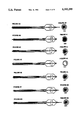
- FIGS. 1A to 1G are views of a preferred embodiment of our catheter/guidewire system.
- FIGS. 2A-2H are profile views and cross-sectional views of the distal aspect of the preferred embodiment of the catheter/guidewire system.
- FIG. 3A is a profile view of a preferred embodiment of the catheter/guidewire system
- enlarged FIG. 3E is a corresponding enlarged cross-sectional view of the balloon component inner member.
- FIG. 3B illustrates the unimpaired coaxial catheter-guidewire mobility of the preferred embodiment
- FIG. 3F is a corresponding enlarged cross-sectional view.
- FIGS. 3C-3D illustrate the change in configuration that transpires within the balloon component inner member with the withdrawal of the catheter component over a taper in the guidewire mandrel.
- FIG. 3G and 3H are corresponding enlarged cross-sectional views of FIGS. 3C and 3D.
- FIGS. 4A-4G are a series of profile views of the distal aspect of the preferred embodiment of the catheter/guidewire system.
- FIGS. 4H to 4N illustrate enlarged cross-sectional views of the balloon component inner member.
- FIG. 5A is a profile view of the distal aspect of another embodiment of a catheter/guidewire system illustrating an elastomeric tubular balloon component inner member.
- FIG. 5D is an enlarged cross-sectional view of the inner member.
- FIG. 5B-5C illustrate the change in configuration that transpires within the elastomeric tubular component as the catheter is withdrawn over a taper in the guidewire, and as the guidewire is withdrawn from the catheter.
- FIGS. 5E and 5F are corresponding enlarged cross-sectional views.
- FIG. 6A is a profile view of the distal aspect of another embodiment of a catheter/guidewire system that contains an elastomeric tubular member disposed outside another tubular member.
- FIG. 6E is an enlarged cross-sectional view.
- FIG. 6B is a full profile view of the balloon component inner member.
- FIGS. 6C-6D illustrate the change in configuration that transpires within an elastomeric tubular member as the catheter is withdrawn over a taper in the guidewire, or the guidewire is withdrawn from the catheter component.
- FIG. 6F is an enlarged cross-sectional view of said inner member.
- FIG. 7A is a profile view of the distal aspect of another embodiment of a catheter/guidewire system that contains a wrapped balloon component inner member.
- FIG. 7D is an enlarged cross-sectional view of the balloon component inner member.
- FIGS. 7B-7C illustrate the change in configuration that transpires within the wrapped balloon component inner member as the catheter is withdrawn over a taper in the guidewire, or the guidewire is withdrawn from the catheter.
- FIGS. 7E and 7F are enlarged cross-sectional views of the balloon component inner member.
- FIGS. 8A-8B illustrate unfolded and folded cross-sectional views of another embodiment of a radially expandable balloon component inner member composed of a tubular member of non-uniform wall thickness.
- FIGS. 9A-9B are cross-sectional views of other embodiments of a radially expandable inner member that consists of a relatively rigid tubular member with overlapping surfaces that is disposed either outside or inside an elastomeric tubular member.
- FIG. 10A is a perspective view of another embodiment of a radially expandable inner member that includes a relatively rigid tubular member 88 disposed either inside or outside of an elastomeric tubular member.
- FIG. 10B illustrates the means by which the tubular member accommodates radial expansion.
- FIG. 11A is a profile view of another embodiment of a catheter/guidewire system that contains a radially expandable balloon component inner member and a non-coaxial multi-lumen catheter shaft.
- FIG. 11D is an enlarged cross-sectional view of the shaft.
- FIG. 11B is a profile view of another embodiment of a catheter/guidewire system that contains a radially expandable balloon component inner member and a non-coaxial multi-lumen catheter shaft.
- FIGS. 11E and 11F are enlarged cross-sectional views of the mid/distal-shaft.
- FIG. 11C is a profile view of another embodiment of a catheter/guidewire system.
- FIGS. 11G and 11H are enlarged cross-sectional views of the mid/distal-shaft.
- FIG. 1 is a series of views of a preferred embodiment of our catheter/guidewire system.
- FIGS. 1B, 1F and 1G are side (or profile) views, while FIGS. 1A, 1C, 1D and 1E are cross-sectional views at different positions along the length of the catheter/guidewire assembly.
- the system consists of a catheter component and a guidewire component.
- the catheter component consists of everything in FIG. 1A except the guidewire 90.
- the guidewire 90 is semi-permanently contained within the catheter, as will be explained further below.
- the catheter consists of a balloon component 50, a multi-channel catheter shaft (see FIG. 1A), and a proximal adapter 100.
- the balloon component is formed of a high strength polymeric material, for example, polyethylene terephthalate, commonly known as PET. The use of this material enables the construction of a high pressure-tolerant balloon that contains particularly thin walls.
- the shaft consists of an outer member 10 and an inner member 14 that are disposed coaxially with respect to one another.
- the catheter thus contains two separate lumens, a guidewire lumen 15 that extends continuously throughout the catheter and an hydraulic lumen 13 that is continuous with the confines of balloon 50 to enable the balloon to be inflated.
- the outer member 10 of the shaft is preferably composed of two or more tubular components joined together end to end (see FIG. 1F).
- the proximal component 17 is more rigid than the distal component 18.
- component 17 is polyimide while component 18 is a polyimide/polyurethane blend. These components are joined by means of well known hydraulically competent bonds.
- the use of two or more components for the shaft improves pushability and trackability relative to conventional catheters which have catheter shafts of uniform rigidity throughout.
- the inner tubular member includes a proximal tubular member and a multi-layered segment 60, 70 that extends throughout the confines of the balloon.
- the multi-layered segment consists of a very flexible and particularly thin-walled tubular member 70 (see FIG. 1C) and a relatively more rigid tubular member 60 (see FIG. 1B).
- This flexible member 70 is considerably larger in luminal profile than the corresponding profile of the guidewire contained therein at the onset of a procedure and, as a result, is folded or wrapped around the wire.
- a relatively more rigid tubular member 60 holds the flexible member folded in place around the guidewire. In FIG. 1B the more rigid member 60 is wrapped around member 70 preventing it from showing in that figure. (FIG.
- the flexible tubular member 70 provides hydraulic competence to the balloon component inner member by preventing fluid used to inflate the balloon from escaping along the guidewire.
- the relatively more rigid tubular member 60 provides column strength to the balloon component inner member.
- tubular member 60 within the mid-span of the balloon, is considerably less than the unfolded profile of tubular member 70.
- the profile of the unfolded tubular member 70 is sufficient to accommodate the largest profile segment of the guidewire contained by the device.
- Tubular members 60 and 70 are joined proximally and distally and they are movable therebetween.
- the proximal end of tubular member 70 is bonded to the shaft outer member 10 at joint 34 and the distal end is bonded to the balloon 50 at joint 38.
- the proximal bond 34 maintains the coaxial relationship between the distal ends of the inner and outer components of the catheter shaft and thus precludes the development of tension/compression distortion of the relatively delicate balloon inner member suspended therebetween.
- the distal bond 38 completes the hydraulic competence of lumen 13.
- tubular member 70 is confined within a space defined by the external surface of guidewire 90 and the luminal surface of tubular member 60, it is not subject to considerable stress during balloon inflation. Furthermore, because tubular member 70 is not required to provide column strength to the balloon, tubular member 70 can be constructed with particularly thin walls. This enables the walls of tubular member 70 to be folded over one another within the confines of member 60 without significantly affecting the crossing profile of the composite structure. Member 60 contains one or more slits 65 that extend longitudinally along its full length, thereby enabling it to expand radially as tubular member 70 unfolds to accommodate changes in the guidewire profile during movement of the catheter or guidewire.
- tubular member 70 is folded longitudinally within the confines of tubular member 60 such that the fold in tubular member 70 is contralateral to the slit in member 60 (see FIG. 2G).
- This configuration minimizes the possibility of the guidewire 90 escaping the confines of member 60.
- the aforementioned configuration permits the construction of a particularly low profile, hydraulically competent inner member that is capable of radial expansion in response to the application of minimal radially directed force.
- the distal portion of the catheter system contains proximal and distal radiopaque marker bands 30, 32 that function to identify the location of the balloon during fluoroscopic evaluation.
- the distal radiopaque marker band 32 and the radiopaque guidewire coil 92 also fluoroscopically identify the distal tip of the catheter and guidewire components of the system respectively.
- the ability to determine the spatial relationship between the catheter and guidewire components, under fluoroscopic viewing, enables the operator to advance and retract the guidewire relative to the catheter without inadvertently withdrawing the guidewire coil within the confines of the balloon.
- the proximal adapter 100 (see FIG. 1G) contains two side ports 110 and 120 which interface with male luer-locking components.
- Sideport 110 provides access to the catheter guidewire lumen 15 and sideport 120 provides access to the catheter hydraulic lumen 13.
- the infusion of fluid into sideport 120 inflates the balloon 50.
- a deformable sealing O-ring 130 is contained between two rotatably disposed elements 134 and 138.
- the interface between elements 134 and 138 is a right-hand screw. Clockwise rotation of element 138 relative to element 134 compresses the flexible O-ring 130 between the opposing surfaces of the proximal adapter 100 and the guidewire 90, thus creating a hydraulically competent seal at the proximal end of the guidewire lumen 15.
- This seal precludes inadvertent loss of blood via the guidewire lumen 15 during the course of an angioplasty procedure.
- the action of this seal tends to seize the guidewire 90 to the catheter and, when closed, restricts coaxial mobility of the guidewire relative to the catheter.
- Counter-clockwise rotation of element 138 relative to element 134 releases the guidewire from the catheter, enabling the operator to freely advance, retract and rotate the guidewire relative to the catheter and thereby direct the system within the confines of the vasculature. It is anticipated that an operator will advance the device within the confines of the vasculature with the seal open, close this seal following manipulation of the device across the confines of the lesion requiring dilatation, and then perform the dilatation.
- a strain relief interface 101 is attached to the catheter shaft outer member 10 and to the distal end of the proximal adapter 100 by means of a cap 102.
- the guidewire 90 is non-uniform in profile.
- the guidewire contains at least one low profile segment that is disposed, at least at the outset of the angioplasty procedure, within the confines of the balloon, as has been described above.
- the guidewire 90 consists of a tapered mandrel, a flat wire ribbon (not shown) and a radiopaque guidewire coil 92.
- the guidewire coil extends over the distal aspect of the mandrel obscuring the ribbon in the drawings.
- the flat wire ribbon extends throughout the length of the interior of the guidewire coil 92.
- the guidewire coil 92 is joined proximally to the guidewire mandrel and to the flat wire ribbon. Distally, the guidewire coil is joined only to the flat wire ribbon.
- the profile of the coil is non-uniform. (See FIG. 1.) This configuration confers a wedge function to the guidewire.
- the distal thirty centimeters of the guidewire mandrel is smaller in profile than the luminal dimensions of the non-expanded balloon component inner member.
- This configuration enables unimpaired coaxial guidewire movement within the confines of the balloon component inner member for a distance of 27 centimeters. (The coil occupies about 3 centimeters.) This feature enhances the reach and cross potential of the device and enables the performance of intraoperative angiography with enhanced efficiency and safety relative to devices that do not provide coaxial catheter/guidewire movement.
- the proximal end of the guidewire contains an adapter (not shown) that interfaces with an extension wire.
- FIGS. 2A and 2B are enlarged profile views of the distal aspect of the preferred embodiment of the catheter/guidewire system.
- member 60 has been partially removed to illustrate folded tubular member 70 contained therein.
- FIGS. 2C-2H illustrate enlarged cross-sectional views of the structure of FIG. 2A.
- FIGS. 3A-3H illustrate the change in configuration of the balloon component inner member that transpires as the catheter is withdrawn over a taper 94 in the guidewire 90.
- the catheter component can be withdrawn for a limited distance (e.g., approximately 27 centimeters in the preferred embodiment) over the guidewire without distorting the configuration of the inner member 60, 70. This occurs because the profile of the segment of the guidewire mandrel in the vicinity of the balloon is less than the non-radially expanded luminal dimensions of the inner member of the balloon. The process of advancing and retracting the relatively larger profile elements of the guidewire through the confines of the balloon provokes modest resistance.
- FIGS. 4A-4G and corresponding enlarged cross-sectional views FIGS. 4H to 4N, illustrate the change in configuration that transpires within the balloon component inner members 60, 70 during withdrawal and readvancement of a non-uniform guidewire component therethrough.
- the catheter of our device can be completely separated from the guidewire by withdrawing the catheter from the guidewire or vice versa.
- a guidewire of either our design or conventional configuration can be advanced through the confines of the catheter component of our device.
- FIGS. 5A-5C illustrate another embodiment of a catheter/guidewire system that contains a radially expandable inner member and a guidewire of non-uniform profile.
- the inner member of this embodiment contains an elastomeric inner tubular member.
- FIGS. 5A-5C illustrate the change in configuration that transpires within the elastomeric tubular member 71 of this embodiment as a non-uniform profile guidewire is advanced and withdrawn therethrough.
- member 60 confers column strength and elastomeric member 71 confers hydraulic competence to the balloon component inner member.
- FIGS. 5D to 5F illustrate the change in thickness that occurs within elastomeric tubular member 71 as it expands and contracts to accommodate changes in the guidewire profile.
- FIGS. 6A-6D illustrate another embodiment of a catheter/guidewire system that contains a radially expandable inner member and a guidewire of non-uniform profile.
- the inner member of this embodiment contains a relatively rigid tubular member 77 that is disposed within an elastomeric tubular member 78.
- FIG. 6A is a profile view of the catheter/guidewire system.
- FIG. 6B contains a profile view of same, but also shows an internal view of region 78.
- tubular member 77 confers column strength
- elastomeric member 78 confers hydraulic competence to the balloon component inner member.
- FIGS. 6C and 6D illustrate the change in configuration that transpires within the inner member of this embodiment as the guidewire is advanced and withdrawn relative to the catheter.
- FIGS. 6E and 6F depict enlarged cross-sections of FIGS. 6A and 6C, respectively.
- FIGS. 7A-7C illustrate another embodiment of a catheter/guidewire system of our invention.
- This embodiment contains a folded, or wrapped, relatively inelastic and yet radially expandable single component inner member 73 that extends within the balloon 50.
- the inner member is composed of a tubular member of uniform wall thickness.
- FIGS. 7B and 7C illustrate the change in configuration that transpires within the single component inner member 73 of this embodiment consequent with the process of advancing or retracting a guidewire of non-uniform profile therethrough.
- Reversible bonding for example by heat, ultrasound or adhesive, or molding, for example by heat, can be used to maintain the desired wrapped or folded configuration.
- FIGS. 7D-7F are corresponding enlarged cross-sectional views.
- FIGS. 8A-8B illustrate cross-sectional views of another embodiment of a radially expandable inner member of a catheter/guidewire system.
- This embodiment consists of a folded or wrapped balloon having an inner member that is composed of a tubular member of non-uniform wall thickness.
- the non-uniform wall thickness enables the construction of an inner member that is more uniform in profile, when folded or wrapped, than does to the use of a tube of relatively uniform wall thickness. (See FIG. 8B).
- This configuration permits radial expansion, and if necessary reversible bonding or molding can be used to maintain the desired wrapped or folded configuration.
- FIGS. 9A-9B illustrate cross-sectional views of another embodiment of a radially expandable inner member of a catheter/guidewire system.
- This embodiment consists of a relatively rigid tubular member 79 that is disposed either outside (see FIG. 9A) or inside (see FIG. 9B) of an elastomeric tubular member 92.
- Tubular member 79 is a relatively rigid tubular structure with overlapping surfaces.
- Tubular member 79 confers column strength to the inner member, while elastomeric tubular member 92 provides hydraulic competence.
- FIGS. 10A-10B illustrate three-dimensional views of another embodiment of a radially expandable inner member of a catheter/guidewire system of our design.
- This embodiment contains a relatively rigid, tubular member 88 that is disposed either over (see FIG. 10A) or under a more flexible or elastomeric tubular member 82.
- Tubular member 88 provides column strength, while elastomeric tubular member 82 confers hydraulic competence to this embodiment.
- FIG. 10B illustrates the change in configuration of member 88 that transpires as it expands radially.
- FIG. 11A illustrates another embodiment of a guidewire-directed dilatation balloon catheter that contains a non-coaxial multi-lumen catheter shaft.
- This figure illustrates that our invention is not limited to the construction of catheters of coaxial shaft construction.
- the device depicted in FIG. 11A contains the preferred configuration for the balloon component inner member of our design, it should be recognized that any inner member, for example, as described above, that confers suitable column strength and permits radial expansion can be used in conjunction with a multi-lumen catheter shaft and guidewire of non-uniform profile.
- This configuration creates a completely separable, highly steerable guidewire-directed dilatation balloon catheter system of lower profile than heretofore possible.
- FIG. 11B illustrates another embodiment of a guidewire-directed dilatation balloon catheter that is similar to the catheter configuration illustrated in FIG. 11A.
- the guidewire component 90 contained with the device, depicted in FIG. 11B exits the confines of the catheter within the mid/distal-shaft of the device.
- This configuration enables the construction of an ultra-low profile guidewire-directed dilatation balloon catheter delivery system that affords the performance of a catheter exchange with enhanced facility and efficiency relative to prior art over-the-wire devices of conventional design.
- FIG. 11C illustrates another embodiment of a guidewire-directed dilatation balloon catheter system that is similar, in many respects to the device depicted in FIG. 11B. This embodiment differs from the previous one by virtue of the configuration of the catheter shaft. The region of the catheter shaft, containing the guidewire component, is largely coaxial.
- our invention enables the construction of an ultra-low profile, highly steerable guidewire-directed dilatation balloon catheter system that accommodates a guidewire of larger proximal and distal proportions relative to the luminal dimensions of all or a portion of the inner member.
- the catheter/guidewire system of our invention permits: (1) unrestricted rotation of the guidewire, (2) unimpaired limited coaxial guidewire mobility, (3) and complete catheter-guidewire separability.
- Our invention enables the construction of a guidewire-directed dilatation balloon catheter system with a substantially lower crossing profile and yet commensurate steerability and safety relative to over-the-wire systems of the prior art.
- Our invention further enables the construction of a catheter/guidewire system that affords the convenience of a fixed-wire or semi-movable device.
- the guidewire contained within our device is non-uniform in profile. All or a segment of the inner member of our device unfolds or expands radially to accommodate changes in the guidewire profile with minimal resistance.
- the use of our invention enables the performance of an angioplasty procedure with less effort and greater finesse than prior art devices.
- the use of our invention enables the performance of an intraoperative angiogram and/or catheter exchange without sacrificing intraliminal access.
Abstract
Description
Claims (13)
Priority Applications (4)
| Application Number | Priority Date | Filing Date | Title |
|---|---|---|---|
| US07/540,957 US5192295A (en) | 1990-06-20 | 1990-06-20 | Angioplasty dilatation balloon catheter/guidewire system |
| DE69127512T DE69127512T2 (en) | 1990-06-20 | 1991-06-10 | Angioplasty catheter system |
| EP91109454A EP0462482B1 (en) | 1990-06-20 | 1991-06-10 | Angioplasty catheter system |
| JP3174713A JP2505932B2 (en) | 1990-06-20 | 1991-06-20 | Angioplasty inflatable balloon catheter / guidewire system |
Applications Claiming Priority (1)
| Application Number | Priority Date | Filing Date | Title |
|---|---|---|---|
| US07/540,957 US5192295A (en) | 1990-06-20 | 1990-06-20 | Angioplasty dilatation balloon catheter/guidewire system |
Publications (1)
| Publication Number | Publication Date |
|---|---|
| US5192295A true US5192295A (en) | 1993-03-09 |
Family
ID=24157605
Family Applications (1)
| Application Number | Title | Priority Date | Filing Date |
|---|---|---|---|
| US07/540,957 Expired - Lifetime US5192295A (en) | 1990-06-20 | 1990-06-20 | Angioplasty dilatation balloon catheter/guidewire system |
Country Status (4)
| Country | Link |
|---|---|
| US (1) | US5192295A (en) |
| EP (1) | EP0462482B1 (en) |
| JP (1) | JP2505932B2 (en) |
| DE (1) | DE69127512T2 (en) |
Cited By (50)
| Publication number | Priority date | Publication date | Assignee | Title |
|---|---|---|---|---|
| US5257974A (en) * | 1992-08-19 | 1993-11-02 | Scimed Life Systems, Inc. | Performance enhancement adaptor for intravascular balloon catheter |
| US5269791A (en) * | 1992-10-09 | 1993-12-14 | Ilya Mayzels | Surgical knot pushing appliance |
| US5306247A (en) * | 1991-12-11 | 1994-04-26 | Schneider (Europe) A.G. | Balloon catheter |
| US5360401A (en) * | 1993-02-18 | 1994-11-01 | Advanced Cardiovascular Systems, Inc. | Catheter for stent delivery |
| US5364354A (en) * | 1991-04-24 | 1994-11-15 | Baxter International Inc. | Exchangeable integrated-wire balloon catheter |
| US5378238A (en) * | 1991-10-15 | 1995-01-03 | Scimed Life Systems, Inc. | Innerless dilatation catheter with balloon stretch or manual valve |
| US5378237A (en) * | 1992-01-17 | 1995-01-03 | Laboratoire Nycomed Ingenop Sa | Dilatation catheter for perfusion |
| US5378236A (en) * | 1992-05-15 | 1995-01-03 | C. R. Bard, Inc. | Balloon dilatation catheter with integral detachable guidewire |
| US5429605A (en) * | 1994-01-26 | 1995-07-04 | Target Therapeutics, Inc. | Microballoon catheter |
| US5454788A (en) * | 1991-04-24 | 1995-10-03 | Baxter International Inc. | Exchangeable integrated-wire balloon catheter |
| US5484408A (en) * | 1989-04-13 | 1996-01-16 | Scimed Life Systems, Inc. | Innerless catheter |
| US5571169A (en) * | 1993-06-07 | 1996-11-05 | Endovascular Instruments, Inc. | Anti-stenotic method and product for occluded and partially occluded arteries |
| US5622188A (en) | 1989-08-18 | 1997-04-22 | Endovascular Instruments, Inc. | Method of restoring reduced or absent blood flow capacity in an artery |
| US5810867A (en) * | 1997-04-28 | 1998-09-22 | Medtronic, Inc. | Dilatation catheter with varied stiffness |
| US5882336A (en) * | 1994-12-30 | 1999-03-16 | Janacek; Jaroslav | Dilation catheter |
| US5968069A (en) * | 1996-08-23 | 1999-10-19 | Scimed Life Systems, Inc. | Stent delivery system having stent securement apparatus |
| US6018211A (en) * | 1993-04-28 | 2000-01-25 | Matsushita Electric Industrial Co., Ltd. | Surface acoustic wave device and method of manufacturing the same |
| US6129707A (en) * | 1998-01-21 | 2000-10-10 | Advanced Cardiovascular Systems, Inc. | Intravascular catheter with expanded distal tip |
| US6231564B1 (en) | 1995-09-29 | 2001-05-15 | Medtronic Ave, Inc. | Storable guidewire system |
| US6270504B1 (en) | 1996-08-23 | 2001-08-07 | Scimed Life Systems, Inc. | Stent delivery system |
| US6283950B1 (en) * | 1998-06-11 | 2001-09-04 | Angiodynamics, Inc. | Occluding wire assembly |
| US6299595B1 (en) | 1999-12-17 | 2001-10-09 | Advanced Cardiovascular Systems, Inc. | Catheters having rapid-exchange and over-the-wire operating modes |
| US6395008B1 (en) * | 1996-08-23 | 2002-05-28 | Scimed Life Systems, Inc. | Stent delivery device using stent cups and mounting collars |
| US6506201B2 (en) | 1996-08-23 | 2003-01-14 | Scimed Life Systems, Inc. | Balloon catheter with stent securement means |
| US20030033000A1 (en) * | 2001-08-09 | 2003-02-13 | Dicaprio Fernando | Stent delivery system |
| US6648854B1 (en) | 1999-05-14 | 2003-11-18 | Scimed Life Systems, Inc. | Single lumen balloon-tipped micro catheter with reinforced shaft |
| US20030236495A1 (en) * | 2002-05-16 | 2003-12-25 | Kennedy Kenneth C. | Non-buckling balloon catheter |
| US20040098082A1 (en) * | 1996-08-23 | 2004-05-20 | Scimed Life Systems, Inc. | Catheter support for stent delivery |
| US20040167440A1 (en) * | 2003-02-26 | 2004-08-26 | Sharrow James S. | Multiple diameter guidewire |
| US6802849B2 (en) * | 1996-08-23 | 2004-10-12 | Scimed Life Systems, Inc. | Stent delivery system |
| US20040236366A1 (en) * | 2002-05-16 | 2004-11-25 | Kennedy Kenneth C. | Non-buckling balloon catheter |
| US20040236276A1 (en) * | 2001-07-03 | 2004-11-25 | Scimed Life Systems, Inc. | Catheter incorporating a high column strength distal tip region |
| US20070106325A1 (en) * | 1997-06-02 | 2007-05-10 | Ladd William G | Methods for trapping emboli |
| US20080183266A1 (en) * | 2007-01-25 | 2008-07-31 | Cardiac Pacemakers, Inc. | Hydraulic actuation of lead fixation member |
| US20080294103A1 (en) * | 2006-02-24 | 2008-11-27 | Adamastor Humberto Pereira | Constructive disposition applied to balloon catheters |
| US20080306441A1 (en) * | 2007-04-10 | 2008-12-11 | Wilson-Cook Medical Inc. | Non-buckling balloon catheter with spring loaded floating flexible tip |
| US20090069748A1 (en) * | 2007-09-12 | 2009-03-12 | Cook Incorporated | Pushable balloon catheter assembly |
| US20100036312A1 (en) * | 2008-06-08 | 2010-02-11 | Hotspur Technologies, Inc. | Apparatus and methods for removing obstructive material from body lumens |
| US20100036410A1 (en) * | 2008-07-03 | 2010-02-11 | Hotspur Technologies, Inc. | Apparatus and methods for treating obstructions within body lumens |
| US20100069880A1 (en) * | 2008-09-18 | 2010-03-18 | Jeffrey Grayzel | Medical guide element with diameter transition |
| US20100125244A1 (en) * | 2008-11-14 | 2010-05-20 | Medtronic Vascular, Inc. | Balloon catheter for crossing a chronic total occlusion |
| US20110125132A1 (en) * | 2008-07-03 | 2011-05-26 | Hotspur Technologies, Inc. | Apparatus and methods for treating obstructions within body lumens |
| US20110125182A1 (en) * | 1997-11-07 | 2011-05-26 | Salviac Limited | Filter element with retractable guidewire tip |
| US7993329B2 (en) | 2002-08-13 | 2011-08-09 | Cook Medical Technologies Llc | ERCP catheter with a removable handle for lithotriptor compatible basket |
| US8926649B2 (en) | 2009-02-18 | 2015-01-06 | Hotspur Technologies, Inc. | Apparatus and methods for treating obstructions within body lumens |
| US9126013B2 (en) | 2012-04-27 | 2015-09-08 | Teleflex Medical Incorporated | Catheter with adjustable guidewire exit position |
| US9731099B2 (en) | 2009-02-18 | 2017-08-15 | Hotspur Technologies, Inc. | Apparatus and methods for treating obstructions within body lumens |
| CN109481828A (en) * | 2018-12-27 | 2019-03-19 | 肖恒军 | A kind of novel seal wire and its application |
| US20210315606A1 (en) * | 2018-08-06 | 2021-10-14 | C.R. Bard, Inc. | Catheter with guided, translatable cutter for active slicing/scoring and related methods |
| US11950800B2 (en) * | 2021-06-18 | 2024-04-09 | C.R. Bard, Inc. | Catheter with guided, translatable cutter for active slicing/scoring and related methods |
Families Citing this family (7)
| Publication number | Priority date | Publication date | Assignee | Title |
|---|---|---|---|---|
| US5484409A (en) * | 1989-08-25 | 1996-01-16 | Scimed Life Systems, Inc. | Intravascular catheter and method for use thereof |
| ZA931943B (en) * | 1992-03-30 | 1993-11-16 | Pameda Nv | Inflatable shaft catheter |
| US5328469A (en) * | 1993-03-19 | 1994-07-12 | Roger Coletti | Hybrid balloon angioplasty catheter and methods of use |
| US5573508A (en) * | 1994-11-22 | 1996-11-12 | Advanced Cardiovascular Systems, Inc. | Catheter with an expandable perfusion lumen |
| US6231543B1 (en) | 1999-04-15 | 2001-05-15 | Intella Interventional Systems, Inc. | Single lumen balloon catheter |
| EP1060759B1 (en) * | 1999-06-15 | 2004-03-31 | Medtronic, Inc. | Medical balloon catheter having an inflation tube with a polyetherimide segment |
| JP2012005704A (en) | 2010-06-25 | 2012-01-12 | Asahi Intecc Co Ltd | Balloon catheter |
Citations (12)
| Publication number | Priority date | Publication date | Assignee | Title |
|---|---|---|---|---|
| US4342315A (en) * | 1979-05-10 | 1982-08-03 | Mallinckrodt, Inc. | Suction catheters with improved suction control valve |
| US4545390A (en) * | 1982-09-22 | 1985-10-08 | C. R. Bard, Inc. | Steerable guide wire for balloon dilatation procedure |
| FR2581882A1 (en) * | 1985-05-14 | 1986-11-21 | Synthelabo | Oesophageal tube |
| EP0246998A2 (en) * | 1986-05-21 | 1987-11-25 | Zeta Ltd. | Cardiac balloon catheter |
| EP0254701A1 (en) * | 1986-07-22 | 1988-01-27 | Medtronic Versaflex, Inc. | Steerable catheter |
| EP0266957A2 (en) * | 1986-11-04 | 1988-05-11 | C.R. Bard, Inc. | Two balloons angiplasty catheter |
| WO1989005609A1 (en) * | 1987-12-22 | 1989-06-29 | Andreas Zeiher | Inflatable catheter for dilating stenosis in body channels |
| US4932959A (en) * | 1988-12-01 | 1990-06-12 | Advanced Cardiovascular Systems, Inc. | Vascular catheter with releasably secured guidewire |
| US4988356A (en) * | 1987-02-27 | 1991-01-29 | C. R. Bard, Inc. | Catheter and guidewire exchange system |
| US5002559A (en) * | 1989-11-30 | 1991-03-26 | Numed | PTCA catheter |
| US5085636A (en) * | 1989-01-13 | 1992-02-04 | Scimed Life Systems, Inc. | Balloon catheter with inflation-deflation valve |
| US5106368A (en) * | 1990-04-20 | 1992-04-21 | Cook Incorporated | Collapsible lumen catheter for extracorporeal treatment |
-
1990
- 1990-06-20 US US07/540,957 patent/US5192295A/en not_active Expired - Lifetime
-
1991
- 1991-06-10 EP EP91109454A patent/EP0462482B1/en not_active Expired - Lifetime
- 1991-06-10 DE DE69127512T patent/DE69127512T2/en not_active Expired - Fee Related
- 1991-06-20 JP JP3174713A patent/JP2505932B2/en not_active Expired - Fee Related
Patent Citations (12)
| Publication number | Priority date | Publication date | Assignee | Title |
|---|---|---|---|---|
| US4342315A (en) * | 1979-05-10 | 1982-08-03 | Mallinckrodt, Inc. | Suction catheters with improved suction control valve |
| US4545390A (en) * | 1982-09-22 | 1985-10-08 | C. R. Bard, Inc. | Steerable guide wire for balloon dilatation procedure |
| FR2581882A1 (en) * | 1985-05-14 | 1986-11-21 | Synthelabo | Oesophageal tube |
| EP0246998A2 (en) * | 1986-05-21 | 1987-11-25 | Zeta Ltd. | Cardiac balloon catheter |
| EP0254701A1 (en) * | 1986-07-22 | 1988-01-27 | Medtronic Versaflex, Inc. | Steerable catheter |
| EP0266957A2 (en) * | 1986-11-04 | 1988-05-11 | C.R. Bard, Inc. | Two balloons angiplasty catheter |
| US4988356A (en) * | 1987-02-27 | 1991-01-29 | C. R. Bard, Inc. | Catheter and guidewire exchange system |
| WO1989005609A1 (en) * | 1987-12-22 | 1989-06-29 | Andreas Zeiher | Inflatable catheter for dilating stenosis in body channels |
| US4932959A (en) * | 1988-12-01 | 1990-06-12 | Advanced Cardiovascular Systems, Inc. | Vascular catheter with releasably secured guidewire |
| US5085636A (en) * | 1989-01-13 | 1992-02-04 | Scimed Life Systems, Inc. | Balloon catheter with inflation-deflation valve |
| US5002559A (en) * | 1989-11-30 | 1991-03-26 | Numed | PTCA catheter |
| US5106368A (en) * | 1990-04-20 | 1992-04-21 | Cook Incorporated | Collapsible lumen catheter for extracorporeal treatment |
Cited By (100)
| Publication number | Priority date | Publication date | Assignee | Title |
|---|---|---|---|---|
| US5484408A (en) * | 1989-04-13 | 1996-01-16 | Scimed Life Systems, Inc. | Innerless catheter |
| US5569201A (en) * | 1989-04-13 | 1996-10-29 | Scimed Life Systems, Inc. | Balloon catheter with distal seal |
| US6090126A (en) * | 1989-04-13 | 2000-07-18 | Scimed Life Systems, Inc. | Catheter seal |
| US5934284A (en) | 1989-08-18 | 1999-08-10 | Endovascular Instruments, Inc | Method for increasing blood flow in vessels |
| US5662701A (en) | 1989-08-18 | 1997-09-02 | Endovascular Instruments, Inc. | Anti-stenotic method and product for occluded and partially occluded arteries |
| US5622188A (en) | 1989-08-18 | 1997-04-22 | Endovascular Instruments, Inc. | Method of restoring reduced or absent blood flow capacity in an artery |
| US5865844A (en) * | 1989-08-18 | 1999-02-02 | Endovascular Instruments, Inc. | Anti-stenotic method and product for occluded and partially occluded arteries |
| US5364354A (en) * | 1991-04-24 | 1994-11-15 | Baxter International Inc. | Exchangeable integrated-wire balloon catheter |
| US5454788A (en) * | 1991-04-24 | 1995-10-03 | Baxter International Inc. | Exchangeable integrated-wire balloon catheter |
| US5378238A (en) * | 1991-10-15 | 1995-01-03 | Scimed Life Systems, Inc. | Innerless dilatation catheter with balloon stretch or manual valve |
| US5306247A (en) * | 1991-12-11 | 1994-04-26 | Schneider (Europe) A.G. | Balloon catheter |
| US5378237A (en) * | 1992-01-17 | 1995-01-03 | Laboratoire Nycomed Ingenop Sa | Dilatation catheter for perfusion |
| US5378236A (en) * | 1992-05-15 | 1995-01-03 | C. R. Bard, Inc. | Balloon dilatation catheter with integral detachable guidewire |
| US5257974A (en) * | 1992-08-19 | 1993-11-02 | Scimed Life Systems, Inc. | Performance enhancement adaptor for intravascular balloon catheter |
| US5338300A (en) * | 1992-08-19 | 1994-08-16 | Scimed Life Systems, Inc. | Performance enhancement adaptor for intravascular balloon catheter |
| US5269791A (en) * | 1992-10-09 | 1993-12-14 | Ilya Mayzels | Surgical knot pushing appliance |
| US5360401A (en) * | 1993-02-18 | 1994-11-01 | Advanced Cardiovascular Systems, Inc. | Catheter for stent delivery |
| US6018211A (en) * | 1993-04-28 | 2000-01-25 | Matsushita Electric Industrial Co., Ltd. | Surface acoustic wave device and method of manufacturing the same |
| US5904146A (en) | 1993-06-07 | 1999-05-18 | Endovascular Instruments, Inc. | Anti-stenotic method and product for occluded and partially occluded arteries |
| US5824057A (en) | 1993-06-07 | 1998-10-20 | Endo-Vascular Instruments, Inc. | Anti-stenotic method and product for occluded and partially occluded arteries |
| US5836316A (en) | 1993-06-07 | 1998-11-17 | Endovascular Instruments, Inc. | Method of restoring reduced or absent blood flow capacity |
| US5842479A (en) | 1993-06-07 | 1998-12-01 | Endovascular Instruments, Inc. | Method of restoring reduced or absent blood flow capacity |
| US5843165A (en) | 1993-06-07 | 1998-12-01 | Endovascular Instruments, Inc. | Method for increasing blood flow in vessels |
| US5571169A (en) * | 1993-06-07 | 1996-11-05 | Endovascular Instruments, Inc. | Anti-stenotic method and product for occluded and partially occluded arteries |
| US5873905A (en) | 1993-06-07 | 1999-02-23 | Endovascular Instruments, Inc. | Anti-stenotic method and product for occluded and partially occluded arteries |
| US6090135A (en) | 1993-06-07 | 2000-07-18 | Endovascular Instruments, Inc. | Anti-stenotic method and product for occluded and partially occluded arteries |
| US20020004680A1 (en) * | 1993-06-07 | 2002-01-10 | Mark Plaia | Anti-stenotic method and product for occluded and partially occluded arteries |
| US5782847A (en) * | 1993-06-07 | 1998-07-21 | Endovascular Instruments, Inc. | Anti-stenotic method for occluded and partially occluded arteries |
| US5429605A (en) * | 1994-01-26 | 1995-07-04 | Target Therapeutics, Inc. | Microballoon catheter |
| WO1995020417A1 (en) * | 1994-01-26 | 1995-08-03 | Target Therapeutics, Inc. | Microballoon catheter |
| US5882336A (en) * | 1994-12-30 | 1999-03-16 | Janacek; Jaroslav | Dilation catheter |
| US6231564B1 (en) | 1995-09-29 | 2001-05-15 | Medtronic Ave, Inc. | Storable guidewire system |
| US6270504B1 (en) | 1996-08-23 | 2001-08-07 | Scimed Life Systems, Inc. | Stent delivery system |
| US6506201B2 (en) | 1996-08-23 | 2003-01-14 | Scimed Life Systems, Inc. | Balloon catheter with stent securement means |
| US20040133263A1 (en) * | 1996-08-23 | 2004-07-08 | Scimed Life Systems, Inc. | Stent delivery system having stent securement apparatus |
| US5968069A (en) * | 1996-08-23 | 1999-10-19 | Scimed Life Systems, Inc. | Stent delivery system having stent securement apparatus |
| US20040098082A1 (en) * | 1996-08-23 | 2004-05-20 | Scimed Life Systems, Inc. | Catheter support for stent delivery |
| US8152819B2 (en) | 1996-08-23 | 2012-04-10 | Boston Scientific Scimed, Inc. | Catheter support for stent delivery |
| US6802849B2 (en) * | 1996-08-23 | 2004-10-12 | Scimed Life Systems, Inc. | Stent delivery system |
| US6395008B1 (en) * | 1996-08-23 | 2002-05-28 | Scimed Life Systems, Inc. | Stent delivery device using stent cups and mounting collars |
| US7670364B2 (en) | 1996-08-23 | 2010-03-02 | Boston Scientific Scimed, Inc. | Stent delivery system having stent securement apparatus |
| US8709062B2 (en) | 1996-08-23 | 2014-04-29 | Boston Scientific Scimed, Inc. | Stent delivery system having stent securement apparatus |
| US6517548B2 (en) | 1996-08-23 | 2003-02-11 | Scimed Life Systems, Inc. | Stent delivery system |
| US20100274343A1 (en) * | 1996-08-23 | 2010-10-28 | Boston Scientific Scimed, Inc. | Catheter Support for Stent Delivery |
| US20100274344A1 (en) * | 1996-08-23 | 2010-10-28 | Boston Scientific Scimed, Inc. | Stent Delivery System Having Stent Securement Apparatus |
| US6663660B2 (en) | 1996-08-23 | 2003-12-16 | Scimed Life Systems, Inc. | Stent delivery system having stent securement apparatus |
| US7749234B2 (en) * | 1996-08-23 | 2010-07-06 | Boston Scientific Scimed, Inc. | Catheter support for stent delivery |
| US6030405A (en) * | 1997-04-28 | 2000-02-29 | Medtronic Inc. | Dilatation catheter with varied stiffness |
| US5810867A (en) * | 1997-04-28 | 1998-09-22 | Medtronic, Inc. | Dilatation catheter with varied stiffness |
| US20070106325A1 (en) * | 1997-06-02 | 2007-05-10 | Ladd William G | Methods for trapping emboli |
| US20110125182A1 (en) * | 1997-11-07 | 2011-05-26 | Salviac Limited | Filter element with retractable guidewire tip |
| US8328842B2 (en) * | 1997-11-07 | 2012-12-11 | Salviac Limited | Filter element with retractable guidewire tip |
| US6793647B1 (en) | 1998-01-21 | 2004-09-21 | Advanced Cardiovascular Systems, Inc. | Intravascular catheter with expanded distal tip |
| US6129707A (en) * | 1998-01-21 | 2000-10-10 | Advanced Cardiovascular Systems, Inc. | Intravascular catheter with expanded distal tip |
| US6283950B1 (en) * | 1998-06-11 | 2001-09-04 | Angiodynamics, Inc. | Occluding wire assembly |
| US6648854B1 (en) | 1999-05-14 | 2003-11-18 | Scimed Life Systems, Inc. | Single lumen balloon-tipped micro catheter with reinforced shaft |
| US6299595B1 (en) | 1999-12-17 | 2001-10-09 | Advanced Cardiovascular Systems, Inc. | Catheters having rapid-exchange and over-the-wire operating modes |
| US6458099B2 (en) | 1999-12-17 | 2002-10-01 | Advanced Cardiovascular Systems, Inc. | Catheters having rapid-exchange and over-the-wire operating modes |
| US7766869B2 (en) * | 2001-07-03 | 2010-08-03 | Boston Scientific Scimed, Inc. | Catheter incorporating a high column strength distal tip region |
| US20040236276A1 (en) * | 2001-07-03 | 2004-11-25 | Scimed Life Systems, Inc. | Catheter incorporating a high column strength distal tip region |
| US8105274B2 (en) * | 2001-07-03 | 2012-01-31 | Boston Scientific Scimed, Inc. | Catheter incorporating a high column strength distal tip region |
| US20100298859A1 (en) * | 2001-07-03 | 2010-11-25 | Boston Scientific Scimed, Inc. | Catheter Incorporating a High Column Strength Distal Tip Region |
| US20030033000A1 (en) * | 2001-08-09 | 2003-02-13 | Dicaprio Fernando | Stent delivery system |
| US6726714B2 (en) | 2001-08-09 | 2004-04-27 | Scimed Life Systems, Inc. | Stent delivery system |
| US20040236366A1 (en) * | 2002-05-16 | 2004-11-25 | Kennedy Kenneth C. | Non-buckling balloon catheter |
| US20030236495A1 (en) * | 2002-05-16 | 2003-12-25 | Kennedy Kenneth C. | Non-buckling balloon catheter |
| US7993329B2 (en) | 2002-08-13 | 2011-08-09 | Cook Medical Technologies Llc | ERCP catheter with a removable handle for lithotriptor compatible basket |
| US8167821B2 (en) | 2003-02-26 | 2012-05-01 | Boston Scientific Scimed, Inc. | Multiple diameter guidewire |
| US20040167440A1 (en) * | 2003-02-26 | 2004-08-26 | Sharrow James S. | Multiple diameter guidewire |
| US20080294103A1 (en) * | 2006-02-24 | 2008-11-27 | Adamastor Humberto Pereira | Constructive disposition applied to balloon catheters |
| US7643886B2 (en) | 2007-01-25 | 2010-01-05 | Cardiac Pacemakers, Inc. | Hydraulic actuation of lead fixation member |
| US20080183266A1 (en) * | 2007-01-25 | 2008-07-31 | Cardiac Pacemakers, Inc. | Hydraulic actuation of lead fixation member |
| US20080306441A1 (en) * | 2007-04-10 | 2008-12-11 | Wilson-Cook Medical Inc. | Non-buckling balloon catheter with spring loaded floating flexible tip |
| US20090069748A1 (en) * | 2007-09-12 | 2009-03-12 | Cook Incorporated | Pushable balloon catheter assembly |
| US10716586B2 (en) | 2008-06-08 | 2020-07-21 | Arrow International, Inc. | Apparatus and methods for removing obstructive material from body lumens |
| US20100036312A1 (en) * | 2008-06-08 | 2010-02-11 | Hotspur Technologies, Inc. | Apparatus and methods for removing obstructive material from body lumens |
| US9855067B2 (en) | 2008-06-08 | 2018-01-02 | Hotspur Technologies, Inc. | Removing obstructive material from body lumens |
| US8939991B2 (en) | 2008-06-08 | 2015-01-27 | Hotspur Technologies, Inc. | Apparatus and methods for removing obstructive material from body lumens |
| US8043313B2 (en) | 2008-07-03 | 2011-10-25 | Hotspur Technologies, Inc | Apparatus and methods for treating obstructions within body lumens |
| US20100036410A1 (en) * | 2008-07-03 | 2010-02-11 | Hotspur Technologies, Inc. | Apparatus and methods for treating obstructions within body lumens |
| US10898695B2 (en) | 2008-07-03 | 2021-01-26 | Arrow International, Inc. | Apparatus and methods for treating obstructions within body lumens |
| US20110125132A1 (en) * | 2008-07-03 | 2011-05-26 | Hotspur Technologies, Inc. | Apparatus and methods for treating obstructions within body lumens |
| US10624656B2 (en) | 2008-07-03 | 2020-04-21 | Arrow International, Inc. | Apparatus and methods for treating obstructions within body lumens |
| US9833599B2 (en) | 2008-07-03 | 2017-12-05 | Hotspur Technologies, Inc. | Apparatus and methods for treating obstructions within body lumens |
| US8945160B2 (en) | 2008-07-03 | 2015-02-03 | Hotspur Technologies, Inc. | Apparatus and methods for treating obstructions within body lumens |
| US20100069880A1 (en) * | 2008-09-18 | 2010-03-18 | Jeffrey Grayzel | Medical guide element with diameter transition |
| US8485969B2 (en) | 2008-09-18 | 2013-07-16 | Jeffrey Grayzel | Medical guide element with diameter transition |
| US9238124B2 (en) | 2008-09-18 | 2016-01-19 | Jeffrey Grayzel | Medical guide element with diameter transition |
| US20100125244A1 (en) * | 2008-11-14 | 2010-05-20 | Medtronic Vascular, Inc. | Balloon catheter for crossing a chronic total occlusion |
| US8021330B2 (en) | 2008-11-14 | 2011-09-20 | Medtronic Vascular, Inc. | Balloon catheter for crossing a chronic total occlusion |
| US9757137B2 (en) | 2009-02-18 | 2017-09-12 | Hotspur Technologies, Inc. | Apparatus and methods for treating obstructions within body lumens |
| US8926649B2 (en) | 2009-02-18 | 2015-01-06 | Hotspur Technologies, Inc. | Apparatus and methods for treating obstructions within body lumens |
| US9101382B2 (en) | 2009-02-18 | 2015-08-11 | Hotspur Technologies, Inc. | Apparatus and methods for treating obstructions within body lumens |
| US9731099B2 (en) | 2009-02-18 | 2017-08-15 | Hotspur Technologies, Inc. | Apparatus and methods for treating obstructions within body lumens |
| US10105517B2 (en) | 2012-04-27 | 2018-10-23 | Teleflex Medical Incorporated | Catheter with adjustable guidewire exit position |
| US9126013B2 (en) | 2012-04-27 | 2015-09-08 | Teleflex Medical Incorporated | Catheter with adjustable guidewire exit position |
| US20210315606A1 (en) * | 2018-08-06 | 2021-10-14 | C.R. Bard, Inc. | Catheter with guided, translatable cutter for active slicing/scoring and related methods |
| CN109481828A (en) * | 2018-12-27 | 2019-03-19 | 肖恒军 | A kind of novel seal wire and its application |
| CN109481828B (en) * | 2018-12-27 | 2024-04-12 | 肖恒军 | Novel guide wire and application thereof |
| US11950800B2 (en) * | 2021-06-18 | 2024-04-09 | C.R. Bard, Inc. | Catheter with guided, translatable cutter for active slicing/scoring and related methods |
Also Published As
| Publication number | Publication date |
|---|---|
| DE69127512T2 (en) | 1998-03-26 |
| JPH04261669A (en) | 1992-09-17 |
| EP0462482B1 (en) | 1997-09-03 |
| DE69127512D1 (en) | 1997-10-09 |
| EP0462482A1 (en) | 1991-12-27 |
| JP2505932B2 (en) | 1996-06-12 |
Similar Documents
| Publication | Publication Date | Title |
|---|---|---|
| US5192295A (en) | Angioplasty dilatation balloon catheter/guidewire system | |
| US5318588A (en) | Radially-expandable tubular elements for use in the construction of medical devices | |
| US5462530A (en) | Intravascular catheter with bailout feature | |
| US5439447A (en) | Balloon dilation catheter with hypotube | |
| US5324259A (en) | Intravascular catheter with means to seal guidewire port | |
| US5558643A (en) | Catheter with NiTi tubular shaft | |
| CA2234894C (en) | Balloon angioplasty catheter with enhanced capability to penetrate a tight arterial stenosis | |
| US5246420A (en) | Highly steerable dilatation balloon catheter system | |
| JP2939893B2 (en) | Interchangeable one piece-wire balloon catheter | |
| US4998917A (en) | High torque steerable dilatation catheter | |
| US20020032459A1 (en) | Radially-expandable tubular elements for use in the construction of medical devices | |
| US5242394A (en) | Steerable dilatation catheter | |
| US5273052A (en) | Guidewire with reversible contact seal for releasable securement to catheter | |
| US5634901A (en) | Method of using a catheter sleeve | |
| US4998923A (en) | Steerable dilatation catheter | |
| US5045061A (en) | Balloon catheter and locking guidewire system | |
| EP0266957B1 (en) | Two balloons angiplasty catheter | |
| US5281200A (en) | Multiple component balloon catheter system and stenosis treatment procedure | |
| US20030065353A1 (en) | Radially-expandable tubular elements for use in the construction of medical devices | |
| US5474537A (en) | Inflatable shaft catheter | |
| US5344413A (en) | Catheter having a tip connector for rapid catheter exchanges | |
| EP1518582B1 (en) | Rapid-exchange balloon catheter with hypotube shaft | |
| WO2004043529A2 (en) | Catheter with full-length core wire shaft for core wire interchangeability | |
| US6932836B2 (en) | Catheter and stent delivery system | |
| EP0486720B1 (en) | Seal for low profile, high performance interventional catheters |
Legal Events
| Date | Code | Title | Description |
|---|---|---|---|
| AS | Assignment |
Owner name: DANFORTH BIOMEDICAL, INC., CALIFORNIA Free format text: ASSIGNMENT OF ASSIGNORS INTEREST.;ASSIGNORS:DANFORTH, JOHN W.;KRAUS, JEFF L.;HORZEWSKI, MICHAEL J.;AND OTHERS;REEL/FRAME:005345/0701 Effective date: 19900619 |
|
| STCF | Information on status: patent grant |
Free format text: PATENTED CASE |
|
| FEPP | Fee payment procedure |
Free format text: PAYOR NUMBER ASSIGNED (ORIGINAL EVENT CODE: ASPN); ENTITY STATUS OF PATENT OWNER: LARGE ENTITY |
|
| FPAY | Fee payment |
Year of fee payment: 4 |
|
| FPAY | Fee payment |
Year of fee payment: 8 |
|
| FEPP | Fee payment procedure |
Free format text: PAT HOLDER NO LONGER CLAIMS SMALL ENTITY STATUS, ENTITY STATUS SET TO UNDISCOUNTED (ORIGINAL EVENT CODE: STOL); ENTITY STATUS OF PATENT OWNER: LARGE ENTITY |
|
| FPAY | Fee payment |
Year of fee payment: 12 |
|
| AS | Assignment |
Owner name: WELLS FARGO CAPITAL FINANCE, LLC, AS COLLATERAL AG Free format text: GRANT OF SECURITY INTEREST IN PATENT RIGHTS;ASSIGNORS:ACCELLENT INC.;ACCELLENT LLC;AMERICAN TECHNICAL MOLDING, INC.;AND OTHERS;REEL/FRAME:023870/0105 Effective date: 20100129 |
|
| AS | Assignment |
Owner name: THE BANK OF NEW YORK MELLON, AS NOTES COLLATERAL A Free format text: SECURITY AGREEMENT;ASSIGNORS:ACCELLENT INC.;ACCELLENT LLC;BRIMFIELD ACQUISITION, LLC;AND OTHERS;REEL/FRAME:023928/0439 Effective date: 20100129 |
|
| AS | Assignment |
Owner name: ACCELLENT INC., MASSACHUSETTS Free format text: RELEASE BY SECURED PARTY;ASSIGNOR:WELLS FARGO CAPITAL FINANCE, LLC, AS COLLATERAL AGENT;REEL/FRAME:032438/0956 Effective date: 20140312 |