US5195474A - Oil supply system in internal conbustion engine - Google Patents
Oil supply system in internal conbustion engine Download PDFInfo
- Publication number
- US5195474A US5195474A US07/850,613 US85061392A US5195474A US 5195474 A US5195474 A US 5195474A US 85061392 A US85061392 A US 85061392A US 5195474 A US5195474 A US 5195474A
- Authority
- US
- United States
- Prior art keywords
- oil
- valve
- supply system
- hydraulic pressure
- oil supply
- Prior art date
- Legal status (The legal status is an assumption and is not a legal conclusion. Google has not performed a legal analysis and makes no representation as to the accuracy of the status listed.)
- Expired - Fee Related
Links
Images


Classifications
-
- F—MECHANICAL ENGINEERING; LIGHTING; HEATING; WEAPONS; BLASTING
- F01—MACHINES OR ENGINES IN GENERAL; ENGINE PLANTS IN GENERAL; STEAM ENGINES
- F01L—CYCLICALLY OPERATING VALVES FOR MACHINES OR ENGINES
- F01L9/00—Valve-gear or valve arrangements actuated non-mechanically
- F01L9/10—Valve-gear or valve arrangements actuated non-mechanically by fluid means, e.g. hydraulic
- F01L9/11—Valve-gear or valve arrangements actuated non-mechanically by fluid means, e.g. hydraulic in which the action of a cam is being transmitted to a valve by a liquid column
- F01L9/12—Valve-gear or valve arrangements actuated non-mechanically by fluid means, e.g. hydraulic in which the action of a cam is being transmitted to a valve by a liquid column with a liquid chamber between a piston actuated by a cam and a piston acting on a valve stem
- F01L9/14—Valve-gear or valve arrangements actuated non-mechanically by fluid means, e.g. hydraulic in which the action of a cam is being transmitted to a valve by a liquid column with a liquid chamber between a piston actuated by a cam and a piston acting on a valve stem the volume of the chamber being variable, e.g. for varying the lift or the timing of a valve
-
- F—MECHANICAL ENGINEERING; LIGHTING; HEATING; WEAPONS; BLASTING
- F01—MACHINES OR ENGINES IN GENERAL; ENGINE PLANTS IN GENERAL; STEAM ENGINES
- F01M—LUBRICATING OF MACHINES OR ENGINES IN GENERAL; LUBRICATING INTERNAL COMBUSTION ENGINES; CRANKCASE VENTILATING
- F01M1/00—Pressure lubrication
- F01M1/02—Pressure lubrication using lubricating pumps
-
- F—MECHANICAL ENGINEERING; LIGHTING; HEATING; WEAPONS; BLASTING
- F01—MACHINES OR ENGINES IN GENERAL; ENGINE PLANTS IN GENERAL; STEAM ENGINES
- F01M—LUBRICATING OF MACHINES OR ENGINES IN GENERAL; LUBRICATING INTERNAL COMBUSTION ENGINES; CRANKCASE VENTILATING
- F01M1/00—Pressure lubrication
- F01M1/12—Closed-circuit lubricating systems not provided for in groups F01M1/02 - F01M1/10
-
- F—MECHANICAL ENGINEERING; LIGHTING; HEATING; WEAPONS; BLASTING
- F01—MACHINES OR ENGINES IN GENERAL; ENGINE PLANTS IN GENERAL; STEAM ENGINES
- F01L—CYCLICALLY OPERATING VALVES FOR MACHINES OR ENGINES
- F01L1/00—Valve-gear or valve arrangements, e.g. lift-valve gear
- F01L1/34—Valve-gear or valve arrangements, e.g. lift-valve gear characterised by the provision of means for changing the timing of the valves without changing the duration of opening and without affecting the magnitude of the valve lift
- F01L1/344—Valve-gear or valve arrangements, e.g. lift-valve gear characterised by the provision of means for changing the timing of the valves without changing the duration of opening and without affecting the magnitude of the valve lift changing the angular relationship between crankshaft and camshaft, e.g. using helicoidal gear
- F01L1/3442—Valve-gear or valve arrangements, e.g. lift-valve gear characterised by the provision of means for changing the timing of the valves without changing the duration of opening and without affecting the magnitude of the valve lift changing the angular relationship between crankshaft and camshaft, e.g. using helicoidal gear using hydraulic chambers with variable volume to transmit the rotating force
- F01L2001/34423—Details relating to the hydraulic feeding circuit
- F01L2001/34446—Fluid accumulators for the feeding circuit
-
- F—MECHANICAL ENGINEERING; LIGHTING; HEATING; WEAPONS; BLASTING
- F01—MACHINES OR ENGINES IN GENERAL; ENGINE PLANTS IN GENERAL; STEAM ENGINES
- F01L—CYCLICALLY OPERATING VALVES FOR MACHINES OR ENGINES
- F01L2820/00—Details on specific features characterising valve gear arrangements
- F01L2820/04—Sensors
- F01L2820/045—Valve lift
-
- F—MECHANICAL ENGINEERING; LIGHTING; HEATING; WEAPONS; BLASTING
- F01—MACHINES OR ENGINES IN GENERAL; ENGINE PLANTS IN GENERAL; STEAM ENGINES
- F01M—LUBRICATING OF MACHINES OR ENGINES IN GENERAL; LUBRICATING INTERNAL COMBUSTION ENGINES; CRANKCASE VENTILATING
- F01M1/00—Pressure lubrication
- F01M1/12—Closed-circuit lubricating systems not provided for in groups F01M1/02 - F01M1/10
- F01M2001/123—Closed-circuit lubricating systems not provided for in groups F01M1/02 - F01M1/10 using two or more pumps
Definitions
- the invention generally relates to an oil supply system in an internal combustion engine comprising a valve operating device which is disposed in a cylinder head coupled to an upper surface of a cylinder block and which includes a valve operating cam shaft connected to a crank shaft rotatably carried in a lower engines body portion including the cylinder block, and valve operation characteristic changing means for changing, in accordance with a variation in hydraulic pressure in a hydraulic pressure chamber, the operation characteristic of an engine valve which is supported in the cylinder head for opening and closing.
- an oil pump for supplying a working oil to the hydraulic pressure chamber in the valve operation characteristic changing means is adapted to pump the working oil from an oil pan in a lower portion of an engine body.
- the oil pump is generally placed in the lower portion of the engine body and therefore, the distance between the oil pump and the hydraulic pressure chamber in valve operation characteristic changing means disposed in the cylinder heand, i.e., in an upper portion of the engine body is relatively long and hence, the supply of the oil to the hydraulic pressure chamber at the start of the engine is liable to be delayed.
- an oil having a nature suitable for the lubrication of a crank shaft and a piston is used as an oil supplied from the oil pump.
- such oil has a large viscosity at a low temperature region, and the supply of an oil having a high viscosity to the hydraulic pressure chamber in the valve operation characteristic changing means in the valve operating device results in a non-smooth operation of the valve operation characteristic changing means and hence, the range of temperature for a normal operation of the valve operation characteristic changing means is limited.
- an oil having a relatively low viscosity at a low temperature region is used, there is a fear of a seizure and a damage occurring in the crank shaft, the piston and the like.
- an object of the present invention to provide an oil supply system in an internal combustion engine, wherein the supply of an oil to the hydraulic pressure chamber at the start of the engine is conducted quickly, thereby providing an increase in range of temperature for the operation of the valve operation characteristic changing means, and also providing an improvement in life of the oil in the valve operating device.
- an oil supply system in an internal combustion engine comprising a valve operating device which is disposed in a cylinder head coupled to an upper surface of a cylinder block and which includes a valve operating cam shaft connected to a crank shaft rotatably carried in a lower engine body portion including the cylinder block, and valve operation characteristic changing means for changing, in accordance with a variation in hydraulic pressure in a hydraulic pressure chamber, the operation characteristic of an engine valve which is supported in the cylinder head for opening and closing, the oil supply system comprising a lower oil supply system comprised of a first oil pump connected to individual oil consumption parts disposed in the lower engine body portion for supplying a first oil, and an upper oil supply system comprised of a second oil pump connected to individual oil consumption parts included in the valve operating device as well as to the hydraulic pressure chamber for supplying a second oil, the lower and upper oil supply systems being disposed independently of each other. This ensures that the second oil pump can be disposed in proximity to the hydraulic pressure chamber, so that an oil having
- the second oil has a viscosity lower than that of the first oil at least at a low temperature. This ensures that the range of temperature for the operation of the valve operation characteristic changing means can be extended towarda lower temperature level.
- a variation rate in visocsity of the second oil with respect to the temperature is smaller than that of the first oil with respect to the temperature and therefore, the lubrication of the valve operating device at a high temperature can be conveniently carried out.
- the oil supply system further includes breather systems independent of each other for an upper engine body portion including the cylinder head, and the lower engine body portion. Therefore, the breathing can effectively be carried out, irrespective of independent provision of the upper and lower oil supply systems.
- FIG. 1 is a schematic flow diagram of oil supply in an internal combustion engines
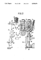
- FIG. 2 is a partially longitudinal sectional view illustrating arrangements of an upper oil supply system and valve operation characteristic changing means
- FIG. 3 is an illustration of breather systems
- FIG. 4 is a graph illustrating variations is viscosity with respect to the temperature.
- an engine body E of a 4-cylinder internal combustion engine includes a lower engine body portion E L having an oil pan Po coupled to a lower portion of a cylinder block Bc, and an upper engine body portion E U having a cylinder head Hc coupled to an upper surface of the cylinder block Bc.
- a valve operating device 1 is disposed in the cylinder head Hc for driving an intake valve V as an engine valve disposed for every cylinder and an exhaust valve (not shown).
- the valve operating device 1 includes a valve operating cam shaft 3 having a cam 2 corresponding to each of the intake valves V for the cylinders as well as a cam (not shown) corresponding to each of the exhaust valves for the cylinders, and valve operation characteristic changing means 4 for the intake valve and valve operation characteristic changing means (not shown) for the exhaust valve, which are disposed for every cylinder to transmit a driving force from the valve operating cam shaft 3 to each of the intake valves and each of the exhaust valves through a hydraulic pressure.
- An endless transmitting belt 8 is wound around a driving pulley 6 mounted on a crank shaft 5 rotatably carried in the lower engine body portion E L and a follower pulley 7 mounted on the valve operating shaft 3, and a rotational power of the crank shaft 5 is transmitted at a reduction ratio of 1/2 to the valve operating cam shaft 3.
- a lower oil supply system O L on the side of the lower engine body portion E L and an upper oil supply system O U on the side of the upper engine body portion E u are disposed independently of each other in the engine body E.
- the lower oil sypply system O L is comprised of a first oil pump P 1 connected to individual oil consumption parts such as a plurality of crank journal portions 9 disposed in the lower engine body portion E L and cooling jets for cooling a sliding-contact surface of each of pistons (not shown) in the cylinders.
- the first oil pump P 1 is connected to the oil pan Po to pump a first oil.
- the upper oil supply system O U is comprised of a second oil pump P 2 connected to oil consumption parts such as a plurality of cam journal portions 10 included in the valve operating device 1 and sliding-contact surfaces of the cams 2, as well as to the valve operation characteristic changing means 4.
- the second oil pump P 2 is connected to an oil bath 14 mounted in the cylinder head Hc to pump a second oil.
- the first oil pump P 1 is disposed in the cylinder block Bc and connected to the crankshaft 5.
- the second oil pump P 2 is disposed in the cylinder head Hc and connected to the valve operating cam shaft 3.
- an oil supply passage 19 including a filter 17 and a pressure control valve 18 is connected to a discharge port of the second oil pump P 2 which pumps a working oil from the oil bath 14, and a relief valve 20 is also connected to the discharge port.
- the oil supply passage 19 is connected to a hydraulic pressure chamber 41 in each of the valve operation characteristic changing means 4, and a branch passage 16, which diverges from a portion between the filter 17 and the pressure control valve 18 in the oil supply passage 19 and includes an orifice 15, is connected to the oil consumption parts such as the cam journal portions 10.
- the cylinder head Hc has an intake valve bore 23 provided therein to lead to an intake port 24 and opened into a top of a combustion chamber 22 defined between the cylinder head Hc and the cylinder block Bc for every cylinder, and the intake valve V capable of opening and closing the intake valve bore 23 is vertically movably disposed in the cylinder head Hc.
- a collar 25 is provided at an upper end of the intake valve V, and a valve spring 26 is mounted in a compressed manner between the collar 25 and the cylinder head Hc.
- the intake valve V is biased upwardly, i.e., in a closing direction by a spring force of the valve spring 26.
- Each of the valve operation characteristic changing means 4 is designed to transmit a driving force from the cam 2 of the valve operating cam shaft 3 rotatably disposed in an upper portion of the cylinder head Hc and to change the operation characteristic of the intake valve V as required by the engine, and is comprised of a transmitting mechanism 31 which is provided in a supporting block 34 fixed to the cylinder head Hc and which is interposed between the intake valve V and the cam 2, and a hydraulic circuit 32 also provided in the supporting block 34 and connected to the hydraulic pressure chamber 41 in the transmitting mechanism 31.
- the transmitting mechanism 31 includes a first cylinder 35 fixed to the supporting block 34 coaxially with the intake valve V, a valve-driving piston 37 slidably received in a lower portion of the first cylinder 35 to abut against an upper end of the intake valve V and define a damper chamber 36 between the valve-driving piston 37 itself and the first cylinder 35, a second cylinder 38 fixed to the supporting block 34 above the cam 2, a lifter 39 slidably received in the supporting block 34 to come into sliding contact with the cam 2, and a cam follower piston 40 slidably received in a lower portion of the second cylinder 38 to abut against an upper end of the lifter 39 and define the hydraulic pressure chamber 41 between the cam follower piston 40 itself and the second cylinder 38.
- the first cylinder 35 has an annular recess 44 provided in an inner surface thereof and normally communicating with the hydraulic pressure chamber 41.
- the annular recess 44 is formed to permit the hydraulic pressure chamber 41 to be put into communication with the damper chamber 36, when the intake valve V, i.e., the valve driving piston 37 is moved by a predetermined amount in an opening direction from its fully-closed position.
- the valve driving piston 37 is provided with a check valve 42 for permitting only a flow of the working oil from the annular recess 44 leading to the hydraulic pressure chamber 41 into the damper chamber 36, and with an orifice 43 for permitting the communication of the annular recess 44 with the damper chamber 36.
- Such transmitting mechanism 31 is in a state shown in FIG. 2, when the intake valve V is in its fully-closed state in which no hydraulic pressure in the hydraulic pressure chamber 41 is released. From this state, if the cam follower piston 490 is urged upwardly in response to the rotation of the cam 2, a hydraulic pressure developed in the hydraulic pressure chamber 41 is passed through the check valve 42 and the orifice 43 into the damper chamber 36, and the valve driving piston 37 is urged downwardly by such hydraulic pressure in the damper chamber 36. In the middle of downward sliding movement of the valve driving piston 37, the hydraulic pressure chamber 41 is put into direct communication with the damper chamber 36 through the annular recess 44, thereby increasing the amount of oil flowing into the damper chamber 36, and the valve driving piston 37 is urged further downwardly. This causes the intake valve V to be opened against the spring force of the valve spring 26.
- the intake valve V is driven upwardly, i.e., in the closing direction by the spring force of the valve spring 26.
- the valve driving piston 37 is also urged upwardly by the closing operation of the intake valve V, and the oil in the damper chamber 36 is returned into the hydraulic pressure chamber 41.
- the direct communication between the annular recess 44 and the damper chamber 36 is released in the middle of the closing operation of the intake valve V, so that the orifice 43 is interposed between the damper chamber 36 and the annular recess 44, the amount of oil returned from the damper chamber 36 to the annular recess 44, i.e., the hydraulic pressure chamber 41 is limited.
- the speed of upward movement of the intake valve V i.e., the valve closing speed is reduced from the middle of the valve-closing operation, and the intake valve V is slowly seated, thereby moderating the shock during seating.
- a lift sensor S is disposed in the supporting block 34 for detecting the upper end of the intake valve V in its fully-closed state.
- the hydraulic pressure chamber 41 in the transmitting mechanism 31 When the hydraulic pressure in the the hydraulic pressure chamber 41 in the transmitting mechanism 31 is released in the middle of the opening operation of the intake valve V, the hydraulic pressure chamber 41 loses a transmitting function enough to overcome the spring force of the valve spring 26 and to continue the opening of the intake valve V. Thus, the intake valve V starts closing by the resilient force of the valve spring 26 from the time of releasing of the hydraulic pressure and as a result, the volume of the hydraulic pressure chamber 41 is reduced.
- the hydraulic pressure release valve 45 is a solenoid valve interposed between an oil passage 49 provided in the supporting block 34 to communicate with the hydraulic pressure chamber 41 and an oil passage 50 provided in the supporting block 34 to communicate with the accumulator 46.
- the one way valve 47 is disposed in the supporting block 34 between the oil passages 50 and 49 to bypass the hydraulic pressure release valve 45 and adapted to be opened to permit only a flow of the oil from the accumulator 46 toward the oil passage 49 and thus the hydraulic pressure chamber 41, when the hydraulic pressure in the oil passage 50 is larger than the hydraulic pressure in the oil passage 49 by a predetermined value or more.
- the check valve 48 is interposed between the oil supply passage 19 and an intermediate portion between the accumulator 46 and the one way valve 47, i.e., the oil passage 50 and is adapted to permit only a flow of the working oil from the oil supply passage 19 toward the oil passage 50.
- the need for a structure for permitting the oil to be dropped between the upper engine body E u and the lower engine body E L of the engine body E is eliminated by providing the upper oil supply system O U and the lower oil supply system O L independently of each other, as described above.
- breaker systems B U and B L are provided independently of each other for the upper and lower engine body portions E U and E L .
- the breather system B U for the upper engine body portion E U is comprised of a communication pipe 54, a separator 55, a gas outlet pipe 56 and a one way valve 57 provided in the gas outlet pipe 56.
- the communication pipe 54 is provided to extent between a point between an air cleaner 51 and a throttle valve 52 in an intake system I connected to the engine body E, and an upper portion of the interior of the upper engine body portion E U , and the separator 55 is disposed to divide the upper portion of the interior of the upper engine body portion E U at a location displaced from an opened end of the communication pipe 54.
- the gas outlet pipe 56 is provided to extend between an intake chamber 53 downstream from the throttle valve 52 in the intake system I and the upper portion of the interior of the upper engine body portion E U divided by the separator 55.
- the breather system B L for the lower engine body portion E L is comprised of a communication pipe 58, a separator 59, a gas outlet pipe 60 and a one way valve 61 provided in the gas outlet pipe 60.
- the communication pipe 58 is provided to extend between a point between the air cleaner 51 and the throttle valve 52 in the intake system I, and an upper portion of the interior of the lower engine body portion E L
- the separator 59 has an expanded volume and communicates with the upper portion of the interior of the lower engine body portion E.sub.
- the gas outlet pipe 60 is provided to extend between the intake chamber 53 in the intake system I and the separator 59.
- a second oil lower in viscosity than the first oil at least at a lower temperature is used in the upper oil supply system O U .
- a second oil having a variation rate in viscosity with respect to the temperature as shown by the straight line C is used.
- An oil such as ULTRA-U (trade name) conventionally used as an engine oil is used as a first oil having a variation in viscosity an shown by the straight line A; an oil such as SILICONE-KF96 (trade name) is used as a second oil having a variation in viscosity as shown by the straight line B, and an oil such as R0-10 (trade name) and FLUID-SPECIAL (trade name) is used as a second oil having a variation in viscosity as shown by the straight line C.
- the kinetic viscosity (cst) of such oils with respect to the temperature is as given in Table 1.
- the second oil pump P 2 in the upper oil supply system O U is disposed in the cylinder head Hc to pump the working oil from the oil bath 14 provided in the cylinder head Hc, and the distance between the hydraulic pressure chamber 41 in the valve operation characteristic changing means 4 and the second oil pump P z can be reduced to a relative small value. Therefore, at the start of the engine, the supply of the oil to the hydraulic pressure chamber 41 in valve operation characteristic changing means 4 can be conducted quickly, leading to an improved responsiveness.
- the first oil circulating through the lower oil supply system O L has a relatively high viscosity at a low temperature, as shown by the straight line A in FIG. 4, and has a nature suitable for the lubrication of the crank shaft 5 and the piston, thereby ensuring that a seizure and damage cannot occur in the crank shaft 5 and the piston.
- the second oil circulating through the upper oil supply system O U has a relatively low viscosity at a low temperature, as shown by the straight lines B and C in FIG. 4, and the range of temperature for the normal operation of the valve operation characteristic changing means 4 can be extended toward a lower temperature level by independently providing the upper and lower oil supply systems O U and O L .
- the use of an oil having a relatively small variation rate in viscosity with respect to the temperature as shown by the straight line B in FIG. 4 are a second oil is convenient for the lubrication of the cam journal portions 10 and the like, because of a smaller reduction in viscosity at a high temperature.
- an oil having a low viscosity over the entire range of temperature as shown by the straight line C in FIG. 4 can be effecttively used for the lubrication of the cam journal portions 10 and the like, because the number of rotation of the valve operating cam shaft 3 is as relatively low as 1/2 of the number of rotations of the crank shaft 5.
- the first oil in the lower oil supply system O L , the first oil is brought into contact with blow-by gas and is heated by a heat of combustion and therefore, the deterioration of the nature of the first oil progresses relatively rapidly.
- the upper oil supply system O U there is no fear of contact of the first oil with the blow-by gas and the first oil is less affected by a heat of combustion and also, the increasse in temperature of the second oil is little, and therefore, the deterioration of the nature of the first oil progresses slowly.
- the second oil is relatively expense, it is possible to prolong the cycle of replacement of the second oil.
- the breather system B U for the upper engine body portion E U and the breather system B L for the lower engine body portion E L are independent of each other and hence, the breathing from the engine body E can be effectively conducted.
Abstract
In an internal combustion engine comprising a valve operating device which is disposed in a cylinder head coupled to an upper surface of a cylinder block and which includes a valve operating cam shaft connected to a crank shaft rotatably carried in a lower engine body portion including the cylinder block, and valve operation characteristic changing means for changing, in accordance with a variation in hydraulic pressure in a hydraulic pressure chamber, the operation characteristics of an engine valve which is supported in the cylinder head for opening and closing, a lower oil supply system and an upper oil supply system are disposed independently of each other. The lower oil supply system is comprised of a first oil pump connected to individual oil consumption parts disposed in a lower engine body portion for supplying a first oil, and the upper oil supply system is comprised of a second oil pump connected to individual oil consumption parts included in the valve operating device as well as to the hydraulic pressure chamber for supplying a second oil. This ensures that the second oil pump can be disposed in proximity to the hydraulic pressure chamber, so that an oil having a characteristic suitable for the operation of the valve operation characteristic changing means can be supplied quickly, and the cycle of replacement of the oil in the upper oil supply system can be prolonged.
Description
1. Field of the Invention
The invention generally relates to an oil supply system in an internal combustion engine comprising a valve operating device which is disposed in a cylinder head coupled to an upper surface of a cylinder block and which includes a valve operating cam shaft connected to a crank shaft rotatably carried in a lower engines body portion including the cylinder block, and valve operation characteristic changing means for changing, in accordance with a variation in hydraulic pressure in a hydraulic pressure chamber, the operation characteristic of an engine valve which is supported in the cylinder head for opening and closing.
2. Description of the Prior Art
Internal combustion engines including such a valve operating device are already known, for example, from Japanese Laid-open patent Application Nos. 229912/86 and 275516/86.
In such internal combustion engines, an oil pump for supplying a working oil to the hydraulic pressure chamber in the valve operation characteristic changing means is adapted to pump the working oil from an oil pan in a lower portion of an engine body. However, the oil pump is generally placed in the lower portion of the engine body and therefore, the distance between the oil pump and the hydraulic pressure chamber in valve operation characteristic changing means disposed in the cylinder heand, i.e., in an upper portion of the engine body is relatively long and hence, the supply of the oil to the hydraulic pressure chamber at the start of the engine is liable to be delayed.
Moreover, in general, an oil having a nature suitable for the lubrication of a crank shaft and a piston is used as an oil supplied from the oil pump. However, such oil has a large viscosity at a low temperature region, and the supply of an oil having a high viscosity to the hydraulic pressure chamber in the valve operation characteristic changing means in the valve operating device results in a non-smooth operation of the valve operation characteristic changing means and hence, the range of temperature for a normal operation of the valve operation characteristic changing means is limited. Thereupon, if an oil having a relatively low viscosity at a low temperature region is used, there is a fear of a seizure and a damage occurring in the crank shaft, the piston and the like.
In addition, in the lower portion of the engine body, the oil is exposed to blow-by gas and heated by heat of combustion and therefore, the deterioration of the oil progresses relatively rapidly. In contrast, in the upper portion of the engine body, there is no fear of contact of the oil with the blow-by gas, and the oil is less affected by heat of combustion, resulting in a relatively little increase in temperature of the oil. Nevertheless, if the same oil is used in the upper and lower portions of the engine body, it is necessary to replace all the oil at a relatively early cycle due to the deterioration of the nature of the oil due to the heating thereof in the lower portion of the engine body.
Accordingly, it is an object of the present invention to provide an oil supply system in an internal combustion engine, wherein the supply of an oil to the hydraulic pressure chamber at the start of the engine is conducted quickly, thereby providing an increase in range of temperature for the operation of the valve operation characteristic changing means, and also providing an improvement in life of the oil in the valve operating device.
To achieve the above object, according to the present invention, there is provided an oil supply system in an internal combustion engine comprising a valve operating device which is disposed in a cylinder head coupled to an upper surface of a cylinder block and which includes a valve operating cam shaft connected to a crank shaft rotatably carried in a lower engine body portion including the cylinder block, and valve operation characteristic changing means for changing, in accordance with a variation in hydraulic pressure in a hydraulic pressure chamber, the operation characteristic of an engine valve which is supported in the cylinder head for opening and closing, the oil supply system comprising a lower oil supply system comprised of a first oil pump connected to individual oil consumption parts disposed in the lower engine body portion for supplying a first oil, and an upper oil supply system comprised of a second oil pump connected to individual oil consumption parts included in the valve operating device as well as to the hydraulic pressure chamber for supplying a second oil, the lower and upper oil supply systems being disposed independently of each other. This ensures that the second oil pump can be disposed in proximity to the hydraulic pressure chamber, so that an oil having a characteristic suitable for the operation of the valve operations characteristic changing means can be supplied quickly, and the cycle of replacement of the oil in the upper oil supply system can be prolonged.
According to another aspect of the present invention, the second oil has a viscosity lower than that of the first oil at least at a low temperature. This ensures that the range of temperature for the operation of the valve operation characteristic changing means can be extended towarda lower temperature level.
According to a further aspect of the present invention, a variation rate in visocsity of the second oil with respect to the temperature is smaller than that of the first oil with respect to the temperature and therefore, the lubrication of the valve operating device at a high temperature can be conveniently carried out.
According to a yet further aspect of the present invention, the oil supply system further includes breather systems independent of each other for an upper engine body portion including the cylinder head, and the lower engine body portion. Therefore, the breathing can effectively be carried out, irrespective of independent provision of the upper and lower oil supply systems.
The above and other objects, features and advantages of the invention will become apparent from a consideration of the following description of the preferred embodiments, taken in conjunction wit the accompanying drawings.
FIG. 1 is a schematic flow diagram of oil supply in an internal combustion engines;
FIG. 2 is a partially longitudinal sectional view illustrating arrangements of an upper oil supply system and valve operation characteristic changing means;
FIG. 3 is an illustration of breather systems; and
FIG. 4 is a graph illustrating variations is viscosity with respect to the temperature.
The present invention will now be described by way of a preferred embodiment in connection with the accompanying drawings.
Referring first to FIG. 1, an engine body E of a 4-cylinder internal combustion engine includes a lower engine body portion EL having an oil pan Po coupled to a lower portion of a cylinder block Bc, and an upper engine body portion EU having a cylinder head Hc coupled to an upper surface of the cylinder block Bc. A valve operating device 1 is disposed in the cylinder head Hc for driving an intake valve V as an engine valve disposed for every cylinder and an exhaust valve (not shown). The valve operating device 1 includes a valve operating cam shaft 3 having a cam 2 corresponding to each of the intake valves V for the cylinders as well as a cam (not shown) corresponding to each of the exhaust valves for the cylinders, and valve operation characteristic changing means 4 for the intake valve and valve operation characteristic changing means (not shown) for the exhaust valve, which are disposed for every cylinder to transmit a driving force from the valve operating cam shaft 3 to each of the intake valves and each of the exhaust valves through a hydraulic pressure. An endless transmitting belt 8 is wound around a driving pulley 6 mounted on a crank shaft 5 rotatably carried in the lower engine body portion EL and a follower pulley 7 mounted on the valve operating shaft 3, and a rotational power of the crank shaft 5 is transmitted at a reduction ratio of 1/2 to the valve operating cam shaft 3.
A lower oil supply system OL on the side of the lower engine body portion EL and an upper oil supply system OU on the side of the upper engine body portion Eu are disposed independently of each other in the engine body E. The lower oil sypply system OL is comprised of a first oil pump P1 connected to individual oil consumption parts such as a plurality of crank journal portions 9 disposed in the lower engine body portion EL and cooling jets for cooling a sliding-contact surface of each of pistons (not shown) in the cylinders. The first oil pump P1 is connected to the oil pan Po to pump a first oil. The upper oil supply system OU is comprised of a second oil pump P2 connected to oil consumption parts such as a plurality of cam journal portions 10 included in the valve operating device 1 and sliding-contact surfaces of the cams 2, as well as to the valve operation characteristic changing means 4. The second oil pump P2 is connected to an oil bath 14 mounted in the cylinder head Hc to pump a second oil. Moreover, the first oil pump P1 is disposed in the cylinder block Bc and connected to the crankshaft 5. And the second oil pump P2 is disposed in the cylinder head Hc and connected to the valve operating cam shaft 3.
Referring to FIG. 2, in the upper oil supply system OU, an oil supply passage 19 including a filter 17 and a pressure control valve 18 is connected to a discharge port of the second oil pump P2 which pumps a working oil from the oil bath 14, and a relief valve 20 is also connected to the discharge port. The oil supply passage 19 is connected to a hydraulic pressure chamber 41 in each of the valve operation characteristic changing means 4, and a branch passage 16, which diverges from a portion between the filter 17 and the pressure control valve 18 in the oil supply passage 19 and includes an orifice 15, is connected to the oil consumption parts such as the cam journal portions 10.
The cylinder head Hc has an intake valve bore 23 provided therein to lead to an intake port 24 and opened into a top of a combustion chamber 22 defined between the cylinder head Hc and the cylinder block Bc for every cylinder, and the intake valve V capable of opening and closing the intake valve bore 23 is vertically movably disposed in the cylinder head Hc. A collar 25 is provided at an upper end of the intake valve V, and a valve spring 26 is mounted in a compressed manner between the collar 25 and the cylinder head Hc. The intake valve V is biased upwardly, i.e., in a closing direction by a spring force of the valve spring 26.
Each of the valve operation characteristic changing means 4 is designed to transmit a driving force from the cam 2 of the valve operating cam shaft 3 rotatably disposed in an upper portion of the cylinder head Hc and to change the operation characteristic of the intake valve V as required by the engine, and is comprised of a transmitting mechanism 31 which is provided in a supporting block 34 fixed to the cylinder head Hc and which is interposed between the intake valve V and the cam 2, and a hydraulic circuit 32 also provided in the supporting block 34 and connected to the hydraulic pressure chamber 41 in the transmitting mechanism 31.
The transmitting mechanism 31 includes a first cylinder 35 fixed to the supporting block 34 coaxially with the intake valve V, a valve-driving piston 37 slidably received in a lower portion of the first cylinder 35 to abut against an upper end of the intake valve V and define a damper chamber 36 between the valve-driving piston 37 itself and the first cylinder 35, a second cylinder 38 fixed to the supporting block 34 above the cam 2, a lifter 39 slidably received in the supporting block 34 to come into sliding contact with the cam 2, and a cam follower piston 40 slidably received in a lower portion of the second cylinder 38 to abut against an upper end of the lifter 39 and define the hydraulic pressure chamber 41 between the cam follower piston 40 itself and the second cylinder 38.
The first cylinder 35 has an annular recess 44 provided in an inner surface thereof and normally communicating with the hydraulic pressure chamber 41. The annular recess 44 is formed to permit the hydraulic pressure chamber 41 to be put into communication with the damper chamber 36, when the intake valve V, i.e., the valve driving piston 37 is moved by a predetermined amount in an opening direction from its fully-closed position. Moreover, the valve driving piston 37 is provided with a check valve 42 for permitting only a flow of the working oil from the annular recess 44 leading to the hydraulic pressure chamber 41 into the damper chamber 36, and with an orifice 43 for permitting the communication of the annular recess 44 with the damper chamber 36.
If the urging force by the cam 2 is released after the intake valve V has been brought into its fully opened state, the intake valve V is driven upwardly, i.e., in the closing direction by the spring force of the valve spring 26. The valve driving piston 37 is also urged upwardly by the closing operation of the intake valve V, and the oil in the damper chamber 36 is returned into the hydraulic pressure chamber 41. When the direct communication between the annular recess 44 and the damper chamber 36 is released in the middle of the closing operation of the intake valve V, so that the orifice 43 is interposed between the damper chamber 36 and the annular recess 44, the amount of oil returned from the damper chamber 36 to the annular recess 44, i.e., the hydraulic pressure chamber 41 is limited. For this reasons, the speed of upward movement of the intake valve V, i.e., the valve closing speed is reduced from the middle of the valve-closing operation, and the intake valve V is slowly seated, thereby moderating the shock during seating.
A lift sensor S is disposed in the supporting block 34 for detecting the upper end of the intake valve V in its fully-closed state.
When the hydraulic pressure in the the hydraulic pressure chamber 41 in the transmitting mechanism 31 is released in the middle of the opening operation of the intake valve V, the hydraulic pressure chamber 41 loses a transmitting function enough to overcome the spring force of the valve spring 26 and to continue the opening of the intake valve V. Thus, the intake valve V starts closing by the resilient force of the valve spring 26 from the time of releasing of the hydraulic pressure and as a result, the volume of the hydraulic pressure chamber 41 is reduced.
The hydraulic circuit 32 serves to release the hydraulic pressure from the hydraulic pressure chamber 41 and supply the working oil to the hydraulic pressure chamber 41. The hydraulic circuit 32 is disposed in the supporting block 34 and includes a hydraulic pressure release valve 45, an accumulator 46, a one way valve 47 and a check valve 48.
The hydraulic pressure release valve 45 is a solenoid valve interposed between an oil passage 49 provided in the supporting block 34 to communicate with the hydraulic pressure chamber 41 and an oil passage 50 provided in the supporting block 34 to communicate with the accumulator 46. The one way valve 47 is disposed in the supporting block 34 between the oil passages 50 and 49 to bypass the hydraulic pressure release valve 45 and adapted to be opened to permit only a flow of the oil from the accumulator 46 toward the oil passage 49 and thus the hydraulic pressure chamber 41, when the hydraulic pressure in the oil passage 50 is larger than the hydraulic pressure in the oil passage 49 by a predetermined value or more. The check valve 48 is interposed between the oil supply passage 19 and an intermediate portion between the accumulator 46 and the one way valve 47, i.e., the oil passage 50 and is adapted to permit only a flow of the working oil from the oil supply passage 19 toward the oil passage 50.
When the hydraulic pressure in the hydraulic pressure chamber 41 is released by the hydraulic pressure releasing valve 45 in the middle of the opening operation of the intake valve V, the hydraulic pressure in the accumulator 46 is returned through the one way valve 47 to the hydraulic pressure chamber 41, and a deficiency is supplied through the check valve 48 to the hydraulic pressure valve 41, until the subsequent opening operation the intake valve V is started. It is required that the hydraulic pressure applied to the oil passage 50 through the check valve 48 is between a lower limit pressure which is a valve opening pressure for the one way valve 47 and an upper limit pressure which is a pressure in the accumulator 46 at the start of accumulation. The hydraulic pressure is controlled by the pressure control valve 18, so that it is within such range.
The need for a structure for permitting the oil to be dropped between the upper engine body Eu and the lower engine body EL of the engine body E is eliminated by providing the upper oil supply system OU and the lower oil supply system OL independently of each other, as described above. Thus, breaker systems BU and BL are provided independently of each other for the upper and lower engine body portions EU and EL. The breather system BU for the upper engine body portion EU is comprised of a communication pipe 54, a separator 55, a gas outlet pipe 56 and a one way valve 57 provided in the gas outlet pipe 56. The communication pipe 54 is provided to extent between a point between an air cleaner 51 and a throttle valve 52 in an intake system I connected to the engine body E, and an upper portion of the interior of the upper engine body portion EU, and the separator 55 is disposed to divide the upper portion of the interior of the upper engine body portion EU at a location displaced from an opened end of the communication pipe 54. The gas outlet pipe 56 is provided to extend between an intake chamber 53 downstream from the throttle valve 52 in the intake system I and the upper portion of the interior of the upper engine body portion EU divided by the separator 55. The breather system BL for the lower engine body portion EL is comprised of a communication pipe 58, a separator 59, a gas outlet pipe 60 and a one way valve 61 provided in the gas outlet pipe 60. The communication pipe 58 is provided to extend between a point between the air cleaner 51 and the throttle valve 52 in the intake system I, and an upper portion of the interior of the lower engine body portion EL, and the separator 59 has an expanded volume and communicates with the upper portion of the interior of the lower engine body portion E.sub.. The gas outlet pipe 60 is provided to extend between the intake chamber 53 in the intake system I and the separator 59.
When the first oil used in the lower oil supply system OL has a variation in viscosity with respect to the temperature as shown by a straight line A in FIG. 4, a second oil lower in viscosity than the first oil at least at a lower temperature, as shown by straight lines B and C, is used in the upper oil supply system OU. Desirably, a second oil having a variation rate in viscosity with respect to the temperature as shown by the straight line C is used.
An oil such as ULTRA-U (trade name) conventionally used as an engine oil is used as a first oil having a variation in viscosity an shown by the straight line A; an oil such as SILICONE-KF96 (trade name) is used as a second oil having a variation in viscosity as shown by the straight line B, and an oil such as R0-10 (trade name) and FLUID-SPECIAL (trade name) is used as a second oil having a variation in viscosity as shown by the straight line C. The kinetic viscosity (cst) of such oils with respect to the temperature is as given in Table 1.
              TABLE 1
______________________________________
              Temperature
Type of oil     -30° C.
                         0° C.
                                 80° C.
                                       130° C.
______________________________________
First oil (straight line A):
                8,000-   550     17    6.0
ULTRA-U (trade-name)
                10,000
Second oil (straight line B):
                200      80      20    12
SILICONE-KF96 (trade
name)
Second oil (straight line C):
RO-10 (trade name)
                300      44      4.0   2.0
FLUID-SPECIAL (trade
                250      45      6.5   --
name)
______________________________________
The operation of this embodiment will be described below. The second oil pump P2 in the upper oil supply system OU is disposed in the cylinder head Hc to pump the working oil from the oil bath 14 provided in the cylinder head Hc, and the distance between the hydraulic pressure chamber 41 in the valve operation characteristic changing means 4 and the second oil pump Pz can be reduced to a relative small value. Therefore, at the start of the engine, the supply of the oil to the hydraulic pressure chamber 41 in valve operation characteristic changing means 4 can be conducted quickly, leading to an improved responsiveness.
The first oil circulating through the lower oil supply system OL has a relatively high viscosity at a low temperature, as shown by the straight line A in FIG. 4, and has a nature suitable for the lubrication of the crank shaft 5 and the piston, thereby ensuring that a seizure and damage cannot occur in the crank shaft 5 and the piston.
The second oil circulating through the upper oil supply system OU has a relatively low viscosity at a low temperature, as shown by the straight lines B and C in FIG. 4, and the range of temperature for the normal operation of the valve operation characteristic changing means 4 can be extended toward a lower temperature level by independently providing the upper and lower oil supply systems OU and OL. The use of an oil having a relatively small variation rate in viscosity with respect to the temperature as shown by the straight line B in FIG. 4 are a second oil is convenient for the lubrication of the cam journal portions 10 and the like, because of a smaller reduction in viscosity at a high temperature. However, even an oil having a low viscosity over the entire range of temperature as shown by the straight line C in FIG. 4 can be effecttively used for the lubrication of the cam journal portions 10 and the like, because the number of rotation of the valve operating cam shaft 3 is as relatively low as 1/2 of the number of rotations of the crank shaft 5.
in the lower oil supply system OL, the first oil is brought into contact with blow-by gas and is heated by a heat of combustion and therefore, the deterioration of the nature of the first oil progresses relatively rapidly. In contrast, in the upper oil supply system OU, there is no fear of contact of the first oil with the blow-by gas and the first oil is less affected by a heat of combustion and also, the increasse in temperature of the second oil is little, and therefore, the deterioration of the nature of the first oil progresses slowly. Thus, even if the second oil is relatively expense, it is possible to prolong the cycle of replacement of the second oil.
Attendant on the independent provision of the upper and lower oil supply systems OU and OL, the breather system BU for the upper engine body portion EU and the breather system BL for the lower engine body portion EL are independent of each other and hence, the breathing from the engine body E can be effectively conducted.
Although the above embodiment has been described in connection with the intake valve used as an engine valve, it will be understood that the present invention can be carried out in connection with an exhaust valve used as an engine valve.
Claims (4)
1. An oil supply system in an internal combustion engine comprising a valve operating device which is disposed in a cylinder head coupled to an upper surface of a cylinder block and which includes a valve operating cam shaft connected to a crank shaft rotatably carried in a lower engine body portion including the cylinder block, and valve operation characteristic changing means for changing, in accordance with a variation in hydraulic pressure in a hydraulic pressure chamber, the operation characteristics of an engine valve which is supported in the cylinder head for opening and closing, said oil supply system comprising
a lower oil supply system comprised of a first oil pump connected to individual oil consumption parts disposed in the lower engine body portion for supplying a first oil, and
an upper oil supply system comprised a second oil pump connected to individual oil consumption parts included in the valve operating device as well as to the hydraulic pressure chamber for supplying a second oil, said lower and upper oil supply systems being disposed independently of each other.
2. An oil supply system in an internal combustion engine according to claim 1, wherein said second oil has a viscosity lower than that of said first oil at least at a low temperature.
3. An oil supply system in an internal combustion engine according to claim 2, wherein a variation rate in viscosity of said second oil with respect to the temperature is smaller than that of said first oil with respect to the temperature.
4. An oil supply system in an internal combustion engine according to claim 1, further including breather systems independent of each other for an upper engine body portion including the cylinder head, and the lower engine body portion.
Applications Claiming Priority (2)
| Application Number | Priority Date | Filing Date | Title |
|---|---|---|---|
| JP1991015489U JPH04111505U (en) | 1991-03-15 | 1991-03-15 | Refueling system in internal combustion engines |
| JP3-15489[U] | 1991-03-15 |
Publications (1)
| Publication Number | Publication Date |
|---|---|
| US5195474A true US5195474A (en) | 1993-03-23 |
Family
ID=11890214
Family Applications (1)
| Application Number | Title | Priority Date | Filing Date |
|---|---|---|---|
| US07/850,613 Expired - Fee Related US5195474A (en) | 1991-03-15 | 1992-03-13 | Oil supply system in internal conbustion engine |
Country Status (4)
| Country | Link |
|---|---|
| US (1) | US5195474A (en) |
| EP (1) | EP0503635B1 (en) |
| JP (1) | JPH04111505U (en) |
| DE (1) | DE69200153T2 (en) |
Cited By (25)
| Publication number | Priority date | Publication date | Assignee | Title |
|---|---|---|---|---|
| US5572968A (en) * | 1994-07-09 | 1996-11-12 | Dr. Ing. H.C.F. Porsche Ag | Internal-combustion engine having an oil return system |
| US5709186A (en) * | 1995-11-24 | 1998-01-20 | Yamaha Hatsudoki Kabushiki Kaisha | Lubrication device for crank chamber supercharged engine |
| US5813376A (en) * | 1996-09-24 | 1998-09-29 | Toyota Jidosha Kabushiki Kaisha | Apparatus for supplying oil in engine |
| US5823159A (en) * | 1997-09-26 | 1998-10-20 | Southwest Research Institute | Independent valve train lubrication system |
| US5915348A (en) * | 1996-11-07 | 1999-06-29 | Ina Walzlager Schaeffler Ohg | Adjusting cylinder of a camshaft adjusting device acted upon by a separate oil supply unit |
| US6234125B1 (en) * | 1998-03-30 | 2001-05-22 | Aft Atlas Fahrzeugtechnik Gmbh | Apparatus for angular adjustment of camshafts relative to crankshafts in combustion engines |
| USRE37268E1 (en) * | 1996-02-10 | 2001-07-10 | INA Wälzlager Schaeffler oHG | Adjusting cylinder of a camshaft adjusting device acted upon by a separate oil supply unit |
| WO2002025071A1 (en) * | 2000-09-19 | 2002-03-28 | The Lubrizol Corporation | Method of operating spark-ignition four-stroke internal combustion engine |
| US6412457B1 (en) * | 1997-08-28 | 2002-07-02 | Diesel Engine Retarders, Inc. | Engine valve actuator with valve seating control |
| US20020114708A1 (en) * | 2000-12-12 | 2002-08-22 | Hunter Douglas G. | Variable displacement vane pump with variable target regulator |
| US6588393B2 (en) | 2000-09-19 | 2003-07-08 | The Lubrizol Corporation | Low-sulfur consumable lubricating oil composition and a method of operating an internal combustion engine using the same |
| WO2003098011A1 (en) * | 2002-05-15 | 2003-11-27 | Robert Bosch Gmbh | Filter for use in a flowing viscous medium |
| US20030231965A1 (en) * | 2002-04-03 | 2003-12-18 | Douglas Hunter | Variable displacement pump and control therefor |
| US6790013B2 (en) | 2000-12-12 | 2004-09-14 | Borgwarner Inc. | Variable displacement vane pump with variable target regulator |
| US20040247471A1 (en) * | 2003-06-05 | 2004-12-09 | Jongmin Lee | Cam-driven secondary oil pump for an internal combustion engine |
| US20050129528A1 (en) * | 2000-12-12 | 2005-06-16 | Borgwarner Inc. | Variable displacement vane pump with variable target reguator |
| US20060104823A1 (en) * | 2002-04-03 | 2006-05-18 | Borgwarner Inc. | Hydraulic pump with variable flow and variable pressure and electric control |
| US20130042826A1 (en) * | 2011-08-17 | 2013-02-21 | GM Global Technology Operations LLC | Engine assembly including valvetrain lubrication system |
| US20130306022A1 (en) * | 2012-05-21 | 2013-11-21 | Chrysler Group Llc | High efficiency oil circuit |
| CN106285828A (en) * | 2016-08-30 | 2017-01-04 | 重庆长安汽车股份有限公司 | A kind of automobile engine variable valve lift system oil channel structures |
| GB2551602A (en) * | 2016-06-20 | 2017-12-27 | Ford Global Tech Llc | An engine assembly |
| US20180371970A1 (en) * | 2015-11-13 | 2018-12-27 | Total Marketing Services | Method for separate lubrication of a drive system for a motor vehicle |
| CN109715911A (en) * | 2016-09-29 | 2019-05-03 | 舍弗勒技术股份两合公司 | The internal combustion engine of ventilation valve transmission device with hydraulic variable |
| US20190195095A1 (en) * | 2017-12-22 | 2019-06-27 | Ford Global Technologies, Llc | Engine variable oil pump diagnostic method |
| CN113464632A (en) * | 2021-05-20 | 2021-10-01 | 蓝箭航天技术有限公司 | Multi-station lubricating oil supply system and control method thereof |
Families Citing this family (15)
| Publication number | Priority date | Publication date | Assignee | Title |
|---|---|---|---|---|
| CN1082132C (en) * | 1995-11-27 | 2002-04-03 | 雅马哈发动机株式会社 | Lubrication device for crank chamber supercharged engine |
| GB9715291D0 (en) | 1997-07-22 | 1997-09-24 | T & N Technology Ltd | Gasket |
| FR2775020B1 (en) * | 1998-02-19 | 2000-05-05 | Peugeot | SYSTEM FOR LUBRICATING MECHANICAL ORGANS OF AN ENGINE CYLINDER HEAD |
| FR2778204B1 (en) * | 1998-04-30 | 2000-06-16 | Peugeot | METHOD FOR REGULATING THE TEMPERATURE OF THE MECHANICAL LUBRICATING OIL OF AN INTERNAL COMBUSTION ENGINE |
| KR100410497B1 (en) * | 2000-12-28 | 2003-12-18 | 현대자동차주식회사 | lubricating device of vehicle |
| DE10117094A1 (en) | 2001-04-06 | 2002-10-17 | Bosch Gmbh Robert | Internal combustion engine with a hydraulic system |
| JP4244597B2 (en) * | 2002-08-27 | 2009-03-25 | トヨタ自動車株式会社 | Internal combustion engine |
| JP4300487B2 (en) * | 2003-02-28 | 2009-07-22 | アイシン精機株式会社 | Engine oil supply device |
| DE602005017953D1 (en) * | 2005-12-27 | 2010-01-07 | Renault Trucks | LUBRICATION SYSTEM AND COMBUSTION ENGINE WITH SUCH A SYSTEM |
| CN101865003B (en) * | 2010-06-18 | 2012-02-01 | 上海幸福摩托车有限公司 | Automobile engine oil pump |
| CN102705037A (en) * | 2011-03-28 | 2012-10-03 | 北汽福田汽车股份有限公司 | Hydraulic tappet oil supply mechanism |
| FR3043717B1 (en) | 2015-11-13 | 2019-09-13 | Total Marketing Services | MOTORIZATION SYSTEM AND ASSOCIATED MOTOR VEHICLE |
| FR3055359B1 (en) * | 2016-08-26 | 2020-06-19 | Total Marketing Services | MOTORIZATION SYSTEM, HIGH-ENGINE AND LUBRICATION AND COOLING METHOD THEREOF |
| JP6669131B2 (en) | 2017-05-31 | 2020-03-18 | トヨタ自動車株式会社 | Oil circulation device for internal combustion engine |
| JP6607232B2 (en) | 2017-05-31 | 2019-11-20 | トヨタ自動車株式会社 | Oil circulation device for internal combustion engine |
Citations (11)
| Publication number | Priority date | Publication date | Assignee | Title |
|---|---|---|---|---|
| DE316612C (en) * | ||||
| JPS5419028A (en) * | 1977-07-12 | 1979-02-13 | Toyota Motor Corp | Overhead cam shaft type internal combustion engine |
| US4392463A (en) * | 1979-08-10 | 1983-07-12 | Nissan Motor Co., Ltd. | Diesel engine having a dual lubrication system |
| FR2605677A1 (en) * | 1986-10-24 | 1988-04-29 | Renault | Greasing device for an internal combustion engine |
| US4890695A (en) * | 1989-05-30 | 1990-01-02 | Caterpillar Inc. | Engine lubrication system |
| JPH0245408A (en) * | 1988-08-04 | 1990-02-15 | Kansai Paint Co Ltd | Skin-beautifying cosmetic |
| US4942855A (en) * | 1988-10-29 | 1990-07-24 | Fuji Jukogyo Kabushiki Kaisha | Lubricating system of a valve mechanism for a double overhead camshaft engine |
| JPH03910A (en) * | 1989-05-26 | 1991-01-07 | Honda Motor Co Ltd | Control device of engine lubricating oil |
| EP0406527A1 (en) * | 1989-07-01 | 1991-01-09 | Dr.Ing.h.c. F. Porsche Aktiengesellschaft | Driving system for two oil pumps of an internal combustion engine with reciprocating pistons |
| US5052355A (en) * | 1989-11-15 | 1991-10-01 | Yamaha Hatsudoki Kabushiki Kaisha | Lubrication system for two cycle engine |
| US5085181A (en) * | 1990-06-18 | 1992-02-04 | Feuling Engineering, Inc. | Electro/hydraulic variable valve timing system |
-
1991
- 1991-03-15 JP JP1991015489U patent/JPH04111505U/en active Pending
-
1992
- 1992-03-12 EP EP92104300A patent/EP0503635B1/en not_active Expired - Lifetime
- 1992-03-12 DE DE69200153T patent/DE69200153T2/en not_active Expired - Fee Related
- 1992-03-13 US US07/850,613 patent/US5195474A/en not_active Expired - Fee Related
Patent Citations (11)
| Publication number | Priority date | Publication date | Assignee | Title |
|---|---|---|---|---|
| DE316612C (en) * | ||||
| JPS5419028A (en) * | 1977-07-12 | 1979-02-13 | Toyota Motor Corp | Overhead cam shaft type internal combustion engine |
| US4392463A (en) * | 1979-08-10 | 1983-07-12 | Nissan Motor Co., Ltd. | Diesel engine having a dual lubrication system |
| FR2605677A1 (en) * | 1986-10-24 | 1988-04-29 | Renault | Greasing device for an internal combustion engine |
| JPH0245408A (en) * | 1988-08-04 | 1990-02-15 | Kansai Paint Co Ltd | Skin-beautifying cosmetic |
| US4942855A (en) * | 1988-10-29 | 1990-07-24 | Fuji Jukogyo Kabushiki Kaisha | Lubricating system of a valve mechanism for a double overhead camshaft engine |
| JPH03910A (en) * | 1989-05-26 | 1991-01-07 | Honda Motor Co Ltd | Control device of engine lubricating oil |
| US4890695A (en) * | 1989-05-30 | 1990-01-02 | Caterpillar Inc. | Engine lubrication system |
| EP0406527A1 (en) * | 1989-07-01 | 1991-01-09 | Dr.Ing.h.c. F. Porsche Aktiengesellschaft | Driving system for two oil pumps of an internal combustion engine with reciprocating pistons |
| US5052355A (en) * | 1989-11-15 | 1991-10-01 | Yamaha Hatsudoki Kabushiki Kaisha | Lubrication system for two cycle engine |
| US5085181A (en) * | 1990-06-18 | 1992-02-04 | Feuling Engineering, Inc. | Electro/hydraulic variable valve timing system |
Cited By (47)
| Publication number | Priority date | Publication date | Assignee | Title |
|---|---|---|---|---|
| US5572968A (en) * | 1994-07-09 | 1996-11-12 | Dr. Ing. H.C.F. Porsche Ag | Internal-combustion engine having an oil return system |
| US5709186A (en) * | 1995-11-24 | 1998-01-20 | Yamaha Hatsudoki Kabushiki Kaisha | Lubrication device for crank chamber supercharged engine |
| USRE37268E1 (en) * | 1996-02-10 | 2001-07-10 | INA Wälzlager Schaeffler oHG | Adjusting cylinder of a camshaft adjusting device acted upon by a separate oil supply unit |
| US5813376A (en) * | 1996-09-24 | 1998-09-29 | Toyota Jidosha Kabushiki Kaisha | Apparatus for supplying oil in engine |
| US5915348A (en) * | 1996-11-07 | 1999-06-29 | Ina Walzlager Schaeffler Ohg | Adjusting cylinder of a camshaft adjusting device acted upon by a separate oil supply unit |
| US6412457B1 (en) * | 1997-08-28 | 2002-07-02 | Diesel Engine Retarders, Inc. | Engine valve actuator with valve seating control |
| US5823159A (en) * | 1997-09-26 | 1998-10-20 | Southwest Research Institute | Independent valve train lubrication system |
| US6234125B1 (en) * | 1998-03-30 | 2001-05-22 | Aft Atlas Fahrzeugtechnik Gmbh | Apparatus for angular adjustment of camshafts relative to crankshafts in combustion engines |
| US6408812B1 (en) | 2000-09-19 | 2002-06-25 | The Lubrizol Corporation | Method of operating spark-ignition four-stroke internal combustion engine |
| US6412468B1 (en) | 2000-09-19 | 2002-07-02 | The Lubrizol Corporation | Method of operating an internal combustion engine |
| US6588393B2 (en) | 2000-09-19 | 2003-07-08 | The Lubrizol Corporation | Low-sulfur consumable lubricating oil composition and a method of operating an internal combustion engine using the same |
| EP1328710A1 (en) * | 2000-09-19 | 2003-07-23 | The Lubrizol Corporation | Method of operating spark-ignition four-stroke internal combustion engine |
| EP1328710A4 (en) * | 2000-09-19 | 2006-05-10 | Lubrizol Corp | Method of operating spark-ignition four-stroke internal combustion engine |
| WO2002025071A1 (en) * | 2000-09-19 | 2002-03-28 | The Lubrizol Corporation | Method of operating spark-ignition four-stroke internal combustion engine |
| US6896489B2 (en) | 2000-12-12 | 2005-05-24 | Borgwarner Inc. | Variable displacement vane pump with variable target regulator |
| US20020114708A1 (en) * | 2000-12-12 | 2002-08-22 | Hunter Douglas G. | Variable displacement vane pump with variable target regulator |
| US7674095B2 (en) | 2000-12-12 | 2010-03-09 | Borgwarner Inc. | Variable displacement vane pump with variable target regulator |
| US6790013B2 (en) | 2000-12-12 | 2004-09-14 | Borgwarner Inc. | Variable displacement vane pump with variable target regulator |
| US20050129528A1 (en) * | 2000-12-12 | 2005-06-16 | Borgwarner Inc. | Variable displacement vane pump with variable target reguator |
| US7018178B2 (en) | 2002-04-03 | 2006-03-28 | Borgwarner Inc. | Variable displacement pump and control therefore for supplying lubricant to an engine |
| US20030231965A1 (en) * | 2002-04-03 | 2003-12-18 | Douglas Hunter | Variable displacement pump and control therefor |
| US20060104823A1 (en) * | 2002-04-03 | 2006-05-18 | Borgwarner Inc. | Hydraulic pump with variable flow and variable pressure and electric control |
| US20060127229A1 (en) * | 2002-04-03 | 2006-06-15 | Borgwarner Inc. | Variable displacement pump and control therefor |
| US7396214B2 (en) | 2002-04-03 | 2008-07-08 | Borgwarner Inc. | Variable displacement pump and control therefor |
| US7726948B2 (en) | 2002-04-03 | 2010-06-01 | Slw Automotive Inc. | Hydraulic pump with variable flow and variable pressure and electric control |
| US20040178130A1 (en) * | 2002-05-15 | 2004-09-16 | Udo Diehl | Filter for use in a flowing viscous medium |
| WO2003098011A1 (en) * | 2002-05-15 | 2003-11-27 | Robert Bosch Gmbh | Filter for use in a flowing viscous medium |
| US20040247471A1 (en) * | 2003-06-05 | 2004-12-09 | Jongmin Lee | Cam-driven secondary oil pump for an internal combustion engine |
| US7008198B2 (en) * | 2003-06-05 | 2006-03-07 | Delphi Technologies, Inc. | Cam operated pump having lost motion shuttle |
| US8667940B2 (en) * | 2011-08-17 | 2014-03-11 | GM Global Technology Operations LLC | Engine assembly including valvetrain lubrication system |
| US20130042826A1 (en) * | 2011-08-17 | 2013-02-21 | GM Global Technology Operations LLC | Engine assembly including valvetrain lubrication system |
| CN102953783B (en) * | 2011-08-17 | 2015-09-02 | 通用汽车环球科技运作有限责任公司 | Comprise the engine pack of valve mechanism lubrication system |
| CN102953783A (en) * | 2011-08-17 | 2013-03-06 | 通用汽车环球科技运作有限责任公司 | Engine assembly including valvetrain lubrication system |
| US20130306022A1 (en) * | 2012-05-21 | 2013-11-21 | Chrysler Group Llc | High efficiency oil circuit |
| US9726056B2 (en) * | 2012-05-21 | 2017-08-08 | Fca Us Llc | High efficiency oil circuit |
| US20180371970A1 (en) * | 2015-11-13 | 2018-12-27 | Total Marketing Services | Method for separate lubrication of a drive system for a motor vehicle |
| GB2551602B (en) * | 2016-06-20 | 2020-10-28 | Ford Global Tech Llc | An engine assembly with improved oil pressure regulation |
| GB2551602A (en) * | 2016-06-20 | 2017-12-27 | Ford Global Tech Llc | An engine assembly |
| CN106285828A (en) * | 2016-08-30 | 2017-01-04 | 重庆长安汽车股份有限公司 | A kind of automobile engine variable valve lift system oil channel structures |
| CN106285828B (en) * | 2016-08-30 | 2019-01-22 | 重庆长安汽车股份有限公司 | A kind of automobile engine variable valve lift system oil channel structures |
| CN109715911A (en) * | 2016-09-29 | 2019-05-03 | 舍弗勒技术股份两合公司 | The internal combustion engine of ventilation valve transmission device with hydraulic variable |
| US20190211718A1 (en) * | 2016-09-29 | 2019-07-11 | Schaeffler Technologies AG & Co. KG | Internal combustion engine with a hydraulically variable gas exchange valve train |
| US10900389B2 (en) * | 2016-09-29 | 2021-01-26 | Schaeffler Technologies AG & Co. KG | Internal combustion engine with a hydraulically variable gas exchange valve train |
| CN109715911B (en) * | 2016-09-29 | 2021-10-12 | 舍弗勒技术股份两合公司 | Internal combustion engine with hydraulically variable gas exchange valve gear |
| US20190195095A1 (en) * | 2017-12-22 | 2019-06-27 | Ford Global Technologies, Llc | Engine variable oil pump diagnostic method |
| US11022010B2 (en) * | 2017-12-22 | 2021-06-01 | Ford Global Technologies, Llc | Engine variable oil pump diagnostic method |
| CN113464632A (en) * | 2021-05-20 | 2021-10-01 | 蓝箭航天技术有限公司 | Multi-station lubricating oil supply system and control method thereof |
Also Published As
| Publication number | Publication date |
|---|---|
| EP0503635A1 (en) | 1992-09-16 |
| DE69200153T2 (en) | 1994-09-15 |
| JPH04111505U (en) | 1992-09-28 |
| DE69200153D1 (en) | 1994-07-07 |
| EP0503635B1 (en) | 1994-06-01 |
Similar Documents
| Publication | Publication Date | Title |
|---|---|---|
| US5195474A (en) | Oil supply system in internal conbustion engine | |
| US4729349A (en) | Oil supply system for a valve operating mechanism in internal combustion engines | |
| US5220891A (en) | Variable cam engine | |
| US7331323B2 (en) | Lubricating oil supplying system for internal combustion engine | |
| US4942855A (en) | Lubricating system of a valve mechanism for a double overhead camshaft engine | |
| US4957085A (en) | Fuel injection system for internal combustion engines | |
| US7726948B2 (en) | Hydraulic pump with variable flow and variable pressure and electric control | |
| GB2431219A (en) | Piston oil spray cooling system with two nozzles | |
| KR20090028787A (en) | Control arrangement for a gas exchange valve in a piston engine and method of controlling a gas exchange valve in a piston engine | |
| US4854273A (en) | Oil pressure control apparatus for an internal combustion engine | |
| JP3023803B2 (en) | Oil supply device for internal combustion engine | |
| GB2198787A (en) | I.C. engine valve timing control | |
| JPH09209733A (en) | Piston lubricating device for engine | |
| US6860250B1 (en) | Engine lubrication system and pressure reducing valve for limiting overhead oil flow | |
| US4907550A (en) | Apparatus for changing operation timing of valves for internal combustion engine | |
| US6920850B2 (en) | Engine lubrication system | |
| JPH08246871A (en) | Lubricating system for internal combustion engine | |
| US4522169A (en) | Variable cylinder device for internal combustion engines | |
| US6810845B1 (en) | Lubrication system using valves to meet various engine oil pressure requirements | |
| JPH03910A (en) | Control device of engine lubricating oil | |
| JPH0218255Y2 (en) | ||
| WO1981000881A1 (en) | Fluid sequence bypass apparatus | |
| JP2832624B2 (en) | Valve train for internal combustion engine | |
| JPH0619765Y2 (en) | Engine oil supply | |
| JPH06200725A (en) | Lubricating oil feeder for engine |
Legal Events
| Date | Code | Title | Description |
|---|---|---|---|
| AS | Assignment |
Owner name: HONDA GIKEN KOGYO KABUSHIKI KAISHA, JAPAN Free format text: ASSIGNMENT OF ASSIGNORS INTEREST.;ASSIGNORS:URATA, YASUHIRO;KUMAGAI, KAZUHIDE;SUZUKI, SHIGERU;REEL/FRAME:006129/0743 Effective date: 19920402 |
|
| FPAY | Fee payment |
Year of fee payment: 4 |
|
| REMI | Maintenance fee reminder mailed | ||
| LAPS | Lapse for failure to pay maintenance fees | ||
| FP | Lapsed due to failure to pay maintenance fee |
Effective date: 20010323 |
|
| STCH | Information on status: patent discontinuation |
Free format text: PATENT EXPIRED DUE TO NONPAYMENT OF MAINTENANCE FEES UNDER 37 CFR 1.362 |