US5200027A - Oil microsensor having interdigitated electrodes with rough surfaces and methods of making and using the same - Google Patents
Oil microsensor having interdigitated electrodes with rough surfaces and methods of making and using the same Download PDFInfo
- Publication number
- US5200027A US5200027A US07/790,401 US79040191A US5200027A US 5200027 A US5200027 A US 5200027A US 79040191 A US79040191 A US 79040191A US 5200027 A US5200027 A US 5200027A
- Authority
- US
- United States
- Prior art keywords
- oil
- sensor
- electrodes
- electrode
- set forth
- Prior art date
- Legal status (The legal status is an assumption and is not a legal conclusion. Google has not performed a legal analysis and makes no representation as to the accuracy of the status listed.)
- Expired - Lifetime
Links
- 238000000034 method Methods 0.000 title claims description 27
- 239000003921 oil Substances 0.000 claims abstract description 193
- VYPSYNLAJGMNEJ-UHFFFAOYSA-N Silicium dioxide Chemical compound O=[Si]=O VYPSYNLAJGMNEJ-UHFFFAOYSA-N 0.000 claims description 22
- NWONKYPBYAMBJT-UHFFFAOYSA-L zinc sulfate Chemical compound [Zn+2].[O-]S([O-])(=O)=O NWONKYPBYAMBJT-UHFFFAOYSA-L 0.000 claims description 21
- 239000003599 detergent Substances 0.000 claims description 19
- 239000000463 material Substances 0.000 claims description 12
- 229910021420 polycrystalline silicon Inorganic materials 0.000 claims description 12
- GRYLNZFGIOXLOG-UHFFFAOYSA-N Nitric acid Chemical compound O[N+]([O-])=O GRYLNZFGIOXLOG-UHFFFAOYSA-N 0.000 claims description 11
- 229910017604 nitric acid Inorganic materials 0.000 claims description 11
- 229920005591 polysilicon Polymers 0.000 claims description 11
- 239000000377 silicon dioxide Substances 0.000 claims description 11
- HCHKCACWOHOZIP-UHFFFAOYSA-N Zinc Chemical compound [Zn] HCHKCACWOHOZIP-UHFFFAOYSA-N 0.000 claims description 10
- 229910052725 zinc Inorganic materials 0.000 claims description 9
- 239000011701 zinc Substances 0.000 claims description 9
- PXHVJJICTQNCMI-UHFFFAOYSA-N Nickel Chemical compound [Ni] PXHVJJICTQNCMI-UHFFFAOYSA-N 0.000 claims description 8
- 229910052782 aluminium Inorganic materials 0.000 claims description 8
- XAGFODPZIPBFFR-UHFFFAOYSA-N aluminium Chemical compound [Al] XAGFODPZIPBFFR-UHFFFAOYSA-N 0.000 claims description 8
- 239000003963 antioxidant agent Substances 0.000 claims description 8
- 235000012239 silicon dioxide Nutrition 0.000 claims description 8
- 238000000151 deposition Methods 0.000 claims description 7
- 229910052581 Si3N4 Inorganic materials 0.000 claims description 6
- HEMHJVSKTPXQMS-UHFFFAOYSA-M Sodium hydroxide Chemical compound [OH-].[Na+] HEMHJVSKTPXQMS-UHFFFAOYSA-M 0.000 claims description 6
- PCHJSUWPFVWCPO-UHFFFAOYSA-N gold Chemical compound [Au] PCHJSUWPFVWCPO-UHFFFAOYSA-N 0.000 claims description 6
- 229910052737 gold Inorganic materials 0.000 claims description 6
- 239000010931 gold Substances 0.000 claims description 6
- 238000004519 manufacturing process Methods 0.000 claims description 6
- HQVNEWCFYHHQES-UHFFFAOYSA-N silicon nitride Chemical compound N12[Si]34N5[Si]62N3[Si]51N64 HQVNEWCFYHHQES-UHFFFAOYSA-N 0.000 claims description 6
- RYGMFSIKBFXOCR-UHFFFAOYSA-N Copper Chemical compound [Cu] RYGMFSIKBFXOCR-UHFFFAOYSA-N 0.000 claims description 5
- XUIMIQQOPSSXEZ-UHFFFAOYSA-N Silicon Chemical compound [Si] XUIMIQQOPSSXEZ-UHFFFAOYSA-N 0.000 claims description 5
- 229910052802 copper Inorganic materials 0.000 claims description 5
- 239000010949 copper Substances 0.000 claims description 5
- 229910052710 silicon Inorganic materials 0.000 claims description 5
- 239000010703 silicon Substances 0.000 claims description 5
- BQCADISMDOOEFD-UHFFFAOYSA-N Silver Chemical compound [Ag] BQCADISMDOOEFD-UHFFFAOYSA-N 0.000 claims description 4
- 229910052759 nickel Inorganic materials 0.000 claims description 4
- 229910052709 silver Inorganic materials 0.000 claims description 4
- 239000004332 silver Substances 0.000 claims description 4
- 238000005530 etching Methods 0.000 claims description 3
- 229910052751 metal Inorganic materials 0.000 claims description 2
- 239000002184 metal Substances 0.000 claims description 2
- 238000001704 evaporation Methods 0.000 claims 3
- 238000000206 photolithography Methods 0.000 claims 3
- 238000009713 electroplating Methods 0.000 claims 1
- 239000010705 motor oil Substances 0.000 abstract description 12
- 238000007254 oxidation reaction Methods 0.000 description 20
- 239000010913 used oil Substances 0.000 description 20
- 230000003647 oxidation Effects 0.000 description 19
- 230000005684 electric field Effects 0.000 description 17
- 239000000047 product Substances 0.000 description 17
- 239000000654 additive Substances 0.000 description 16
- 239000000314 lubricant Substances 0.000 description 13
- 239000002270 dispersing agent Substances 0.000 description 12
- 230000002378 acidificating effect Effects 0.000 description 10
- 239000000376 reactant Substances 0.000 description 10
- 239000000523 sample Substances 0.000 description 10
- 238000006243 chemical reaction Methods 0.000 description 9
- 239000002253 acid Substances 0.000 description 8
- 238000009792 diffusion process Methods 0.000 description 8
- 235000006708 antioxidants Nutrition 0.000 description 7
- 230000008859 change Effects 0.000 description 7
- 239000000356 contaminant Substances 0.000 description 7
- 238000007598 dipping method Methods 0.000 description 6
- 238000003411 electrode reaction Methods 0.000 description 6
- 230000006698 induction Effects 0.000 description 6
- 238000005259 measurement Methods 0.000 description 6
- 238000004458 analytical method Methods 0.000 description 5
- 230000003247 decreasing effect Effects 0.000 description 5
- 230000000694 effects Effects 0.000 description 5
- 238000005036 potential barrier Methods 0.000 description 5
- 239000000203 mixture Substances 0.000 description 4
- 230000035945 sensitivity Effects 0.000 description 4
- LYCAIKOWRPUZTN-UHFFFAOYSA-N Ethylene glycol Chemical compound OCCO LYCAIKOWRPUZTN-UHFFFAOYSA-N 0.000 description 3
- 229910007277 Si3 N4 Inorganic materials 0.000 description 3
- 230000000996 additive effect Effects 0.000 description 3
- 230000003078 antioxidant effect Effects 0.000 description 3
- QVGXLLKOCUKJST-UHFFFAOYSA-N atomic oxygen Chemical compound [O] QVGXLLKOCUKJST-UHFFFAOYSA-N 0.000 description 3
- 230000015556 catabolic process Effects 0.000 description 3
- 239000002800 charge carrier Substances 0.000 description 3
- 229910052681 coesite Inorganic materials 0.000 description 3
- 238000002485 combustion reaction Methods 0.000 description 3
- 229910052906 cristobalite Inorganic materials 0.000 description 3
- 238000006731 degradation reaction Methods 0.000 description 3
- 238000006073 displacement reaction Methods 0.000 description 3
- 230000007246 mechanism Effects 0.000 description 3
- 238000012544 monitoring process Methods 0.000 description 3
- 229910052760 oxygen Inorganic materials 0.000 description 3
- 239000001301 oxygen Substances 0.000 description 3
- 238000007788 roughening Methods 0.000 description 3
- 229910052682 stishovite Inorganic materials 0.000 description 3
- 229910052905 tridymite Inorganic materials 0.000 description 3
- OFBQJSOFQDEBGM-UHFFFAOYSA-N Pentane Chemical compound CCCCC OFBQJSOFQDEBGM-UHFFFAOYSA-N 0.000 description 2
- 239000000969 carrier Substances 0.000 description 2
- 239000004020 conductor Substances 0.000 description 2
- 238000000113 differential scanning calorimetry Methods 0.000 description 2
- 238000003487 electrochemical reaction Methods 0.000 description 2
- 239000003792 electrolyte Substances 0.000 description 2
- 150000002430 hydrocarbons Chemical group 0.000 description 2
- 230000001050 lubricating effect Effects 0.000 description 2
- 238000005461 lubrication Methods 0.000 description 2
- 150000007530 organic bases Chemical class 0.000 description 2
- 230000001590 oxidative effect Effects 0.000 description 2
- 230000008569 process Effects 0.000 description 2
- 239000002904 solvent Substances 0.000 description 2
- 239000000126 substance Substances 0.000 description 2
- 238000012360 testing method Methods 0.000 description 2
- VYZAMTAEIAYCRO-UHFFFAOYSA-N Chromium Chemical compound [Cr] VYZAMTAEIAYCRO-UHFFFAOYSA-N 0.000 description 1
- ZOKXTWBITQBERF-UHFFFAOYSA-N Molybdenum Chemical compound [Mo] ZOKXTWBITQBERF-UHFFFAOYSA-N 0.000 description 1
- 238000009825 accumulation Methods 0.000 description 1
- 229910001420 alkaline earth metal ion Inorganic materials 0.000 description 1
- 150000001450 anions Chemical class 0.000 description 1
- 125000003118 aryl group Chemical group 0.000 description 1
- 239000012298 atmosphere Substances 0.000 description 1
- 239000006227 byproduct Substances 0.000 description 1
- 239000003990 capacitor Substances 0.000 description 1
- 229910052804 chromium Inorganic materials 0.000 description 1
- 239000011651 chromium Substances 0.000 description 1
- 238000000576 coating method Methods 0.000 description 1
- 238000005260 corrosion Methods 0.000 description 1
- 230000007797 corrosion Effects 0.000 description 1
- 230000008021 deposition Effects 0.000 description 1
- 230000007613 environmental effect Effects 0.000 description 1
- 238000011156 evaluation Methods 0.000 description 1
- 239000000446 fuel Substances 0.000 description 1
- 238000010438 heat treatment Methods 0.000 description 1
- 238000012625 in-situ measurement Methods 0.000 description 1
- 238000011065 in-situ storage Methods 0.000 description 1
- 230000001788 irregular Effects 0.000 description 1
- 150000002605 large molecules Chemical class 0.000 description 1
- 239000007791 liquid phase Substances 0.000 description 1
- MHCFAGZWMAWTNR-UHFFFAOYSA-M lithium perchlorate Chemical compound [Li+].[O-]Cl(=O)(=O)=O MHCFAGZWMAWTNR-UHFFFAOYSA-M 0.000 description 1
- 229910001486 lithium perchlorate Inorganic materials 0.000 description 1
- 239000010687 lubricating oil Substances 0.000 description 1
- 229920002521 macromolecule Polymers 0.000 description 1
- 230000007257 malfunction Effects 0.000 description 1
- 238000002156 mixing Methods 0.000 description 1
- 239000003607 modifier Substances 0.000 description 1
- 229910052750 molybdenum Inorganic materials 0.000 description 1
- 239000011733 molybdenum Substances 0.000 description 1
- 230000000877 morphologic effect Effects 0.000 description 1
- 125000000962 organic group Chemical group 0.000 description 1
- TWNQGVIAIRXVLR-UHFFFAOYSA-N oxo(oxoalumanyloxy)alumane Chemical compound O=[Al]O[Al]=O TWNQGVIAIRXVLR-UHFFFAOYSA-N 0.000 description 1
- 230000001737 promoting effect Effects 0.000 description 1
- 230000004044 response Effects 0.000 description 1
- 239000000758 substrate Substances 0.000 description 1
- 230000003746 surface roughness Effects 0.000 description 1
- 230000000007 visual effect Effects 0.000 description 1
- XLYOFNOQVPJJNP-UHFFFAOYSA-N water Substances O XLYOFNOQVPJJNP-UHFFFAOYSA-N 0.000 description 1
Images


Classifications
-
- G—PHYSICS
- G01—MEASURING; TESTING
- G01N—INVESTIGATING OR ANALYSING MATERIALS BY DETERMINING THEIR CHEMICAL OR PHYSICAL PROPERTIES
- G01N33/00—Investigating or analysing materials by specific methods not covered by groups G01N1/00 - G01N31/00
- G01N33/26—Oils; viscous liquids; paints; inks
- G01N33/28—Oils, i.e. hydrocarbon liquids
- G01N33/2888—Lubricating oil characteristics, e.g. deterioration
-
- G—PHYSICS
- G01—MEASURING; TESTING
- G01N—INVESTIGATING OR ANALYSING MATERIALS BY DETERMINING THEIR CHEMICAL OR PHYSICAL PROPERTIES
- G01N27/00—Investigating or analysing materials by the use of electric, electrochemical, or magnetic means
- G01N27/02—Investigating or analysing materials by the use of electric, electrochemical, or magnetic means by investigating impedance
- G01N27/22—Investigating or analysing materials by the use of electric, electrochemical, or magnetic means by investigating impedance by investigating capacitance
- G01N27/226—Construction of measuring vessels; Electrodes therefor
Definitions
- the invention relates to oil sensors, and in particular, to oil sensors having interdigitated two-electrode structure with rough surfaces and methods of making and using the same.
- Proper lubrication is essential to engine life.
- engine oil When engine oil is continuously exposed to high temperatures, high pressure and an oxidizing (combustion) environment, the oil will deteriorate and lose its lubricating effectiveness. To protect the engine the deteriorated oil should be changed.
- Oil lubricants have been used to lubricate and cool components of operating machinery. Often, as the oil lubricant performs its functions it undergoes thermal-oxidation degradation. It is also known that the addition of additive packages to the lubricant enhance and prolong the lubricant's useful life. However, after extended use, the additives of the lubricant are consumed and the useful life of the lubricant ends. Extended use of the lubricant beyond its useful life results in excessive component wear and eventual failure of the machinery. Naturally, it would be desirable to determine the point at which a lubricant's useful life ends so that it may be discarded and replaced with a new lubricant to insure the continued, safe, non-damaging operation of the machinery.
- Oil sensors having two electrodes in an interdigitated pattern are known. In operation, these oil sensors are immersed in an engine oil, and a saw-tooth AC voltage is applied to the electrodes. An electrochemical current with its magnitude depending upon the oil condition can be collected by the sensor. Normally, the use of an interdigitated two-electrode structure sensor has associated problems in differentiating between new and used oil because both oils have large quantities of chemically reactive species that produce higher sensor current or higher voltage when the sensor current is converted to a voltage output through an electronic circuit.
- This invention describes how to solve the selectivity problem of prior art oil sensors.
- a feature of the present oil sensor is that the electrode surfaces are processed to make them rough.
- the invention includes the discovery that the sensitivity problem of differentiating between new and used oils, due to both oils having large quantities of chemically reactive species, can be resolved by roughing an oil sensor's electrodes.
- the invention includes the discovery that local field enhancement is created at the tips of an electrode having rough surfaces.
- the invention includes the discovery that the regional high field produced by the rough surfaces helps to lower the potential barrier for the chemical reaction and enhance the reaction rate at the oil/electrode interface.
- the invention includes the discovery that the first portion of the output voltage of an oil having a detergent in it can be suppressed by using electrodes with rough surfaces.
- a preferred embodiment includes an oil microsensor having interdigitated electrodes with rough surfaces.
- the enhanced electrode reaction also increases the sensor output current.
- the oil contains abundant heavy molecules having low diffusivity such as detergent in new oils, the slow molecular diffusion will limit the increase of the output current of new oils. Consequently, the roughing of the sensor electrode surface results in increased sensitivity for degraded oil and suppressed unwanted signal for new oil.
- the electrical fields near the tips of the roughened electrode surfaces will be enhanced and will have a higher than average electric field.
- This regional high field helps to lower the potential barrier for the chemical reaction and enhance the reaction rate at the electrodes.
- the enhanced electrode reaction also increases the sensor output current.
- the oil contains abundant low diffusivity molecules, such as the detergent in new oils, slow molecule diffusion will limit the increase of the output current.
- roughening electrodes will result in increased sensitivity of the sensor for the electroactive degraded oil products but not change the sensitivity for the heavy molecules found in new oils.
- the invention also includes a method of making and using the electrodes and sensors as described or claimed hereafter.
- the sensor insensitive to the oil brand used; (2) the sensor indirectly monitors the key parameters, such as the acid number of the oil and the thermal stability of the oil (measured by differential scanning calorimetry to determine the oxidation induction time); (3) its small size allows in-line measurement; (4) it has a short response time and can produce results in less than one minute; (5) it can be prepared by IC (integrated circuit) fabrication techniques; and (6) the sensor may be prepared by batch fabrication which means potentially low cost.
- Oil sensors having roughened electrodes are capable of quantitatively sensing the useful life of oil particularly automotive oils used in automotive engines. Despite the fact that high concentrations of active species are present in both new and used oils, roughened electrodes are capable of distinguishing quantitatively between deteriorated oil, and new oil or still useful oil. Small but sharp tips on electrodes create electric field enhancement around them, which increases the charge exchange rate at the electrodes by lowering the potential barrier there.
- a roughened electrode produces an electric field enhancement of about two to about ten times the average electric field of smooth electrodes. For example, 5 volts applied between two smooth electrodes 5 microns apart may have an average electric field of 1 ⁇ 10 4 volts per centimeter.
- a rough electrode according to the present invention would have an electric field of about 2 ⁇ 10 4 to about 10 ⁇ 10 4 volts per centimeter at the tips or protrusions caused by roughening the electrode.
- an electric field enhancement is produced of about two to ten times the average electric field of smooth electrodes. Maintaining the high charge exchange rate at the electrode requires re-supplying the charge carriers to the electrodes through either diffusion or drifting by the electric field. Local field enhancement produced by roughing the electrode surfaces has little effect on heavy molecules, such as detergents and dispersants in new oils. These heavy molecules have low diffusivities and cannot respond to the demand of supplying more reacting species to the electrode.
- Light molecules, such as fragmented oil molecules, oxidation products, and engine blow-by contaminants in badly degraded oils have high diffusivities and can respond to the demand and supply more charges to the electrode. Consequently, the local electric field enhancement created at the roughened electrodes favors the collection of charge carriers in used oils resulting in higher sensor outputs as compared with new oils.
- the oil sensor having roughened electrodes has a current or voltage output with a magnitude that continually increases quantitatively with the continually decreasing useful life of the oil during use. The addition of fresh oil to used oil will not affect the ability to quantitatively or qualitatively determine the end of the useful life of the fresh/used oil mixture.
- the present invention allows the oil to be evaluated without the need to remove the oil from the equipment that it lubricates and without the need to add solvents, organic bases or electrolytes (such as lithium perchlorate) or to place the oil into an electrolytic cell (i.e., the oil measurement may be made in situ).
- FIG. 1 is a photomicrograph of a finished sensor wherein the electrodes have been roughened by dipping the electrodes in a zincate solution for 25.5 seconds.
- FIG. 2 is a photomicrograph of a finished sensor having the electrodes roughened by dipping the electrodes in a zincate solution for 33 seconds.
- FIG. 3 is a photomicrograph of a finished sensor having the electrodes roughened by dipping the electrodes in a zincate solution for 48 seconds.
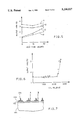
- FIG. 4 is a graphical representation of a sensor output voltage for a different test-oil samples using electrodes with surfaces having varying degrees of roughness.
- FIG. 5 is a graphical representation of the sensor output voltage at varying frequencies for electrodes having varying degrees of surface roughness.
- FIG. 6 is a graphical representation of a sensor output voltage of automotive oil in an automotive engine as a function of miles that the automobile was driven.
- FIG. 7 is a side cross-sectional view of an oil sensor according to the present invention showing rough electrode surfaces.
- FIG. 8 is an illustration of an oil sensor according to the present invention positioned in an oil passage of an engine.
- This invention involves the creation of rough electrode surfaces in an interdigitated structure.
- the electric field near the tips may be several times higher than the average electric field.
- the enhancement factor is a function of the geometrical shapes and is believed to have a value of 2 to 10 times that of smooth electrode sensors.
- This field enhancement will increase the charge exchange rate at the electrode/oil interface because the high electric field lowers the potential barrier for the electrochemical reaction at the electrodes.
- the major reactants in new oils are heavy, long-chain, low-diffusivity molecules with molecular weight more than 250, such as detergents and dispersants. Faster electrode reactions in new oil samples can only slightly increase the current collected by the electrodes because the supply of these carriers are limited by the slow diffusion.
- the oxidation products in the used oils are light, fragmented, short-chain molecules with molecular weight lighter than 125, which have higher diffusivities than the detergents.
- the fast diffusion of the reactants can maintain the higher charge exchange rate caused by the field enhancement resulting in higher steady state sensor current. Therefore, the result of creating rough electrodes is a high output in used oil but not in new oils.
- Proper lubrication is essential to a life of any machine and in particular to automotive engines.
- oil When an automotive engine oil is continuously exposed to high temperatures, high pressures and oxidizing combustion environment, oil will deteriorate and loss it lubricating effectiveness thus requiring replacement of the automotive engine oil.
- a sensor which can inform drivers about the condition of their automotive engine oil.
- Oils useful in practicing the present invention vary greatly in their composition. These oils typically include electrochemically active species in addition to material acting only as lubricants. Electrochemically active species include detergents, dispersants, antioxidants and by-products of the same produced during the use of the oil to lubricate an engine.
- the amount of active species in an oil may vary greatly but for SG-type oil are typically present in an amount ranging from about 10 to about 20 weight percent of the oil.
- the active species may include at least one material selected from the group consisting of detergents, dispersants and additives for corrosion resistance, wear resistance, and antioxidant such as zinc dialkyldithiophosphate (ZDP).
- ZDP zinc dialkyldithiophosphate
- the detergents and dispersants perform the function of removing contaminants from the piston and cylinder wall surfaces.
- detergents include at least those compositions having alkaline earth metal ions and hydrocarbon chains.
- the molecular weight of the detergent may range from about 250 to about 2500.
- the amount of detergent in the oil may range from about 0.1 to about 5 weight percent of the oil.
- dispersants include at least those compositions having hydrocarbon skeletons with polar heads. The dispersant prevents contaminates from affecting the stability of the liquid phase.
- the amount of dispersant in the oil may range from about 0.1 to about 25 weight percent of the oil.
- Other additives, typically antioxidants such as ZDP may be present in an amount ranging from about 0.1 to about 25 weight percent of the oil. The antioxidant prevents oxidation of the base stock.
- Preferred oils are automotive oils. Suitable commercially available automobile oils include for example Mobil 1, Sunoco Ultra, Quaker-State, Valvoline, Pennzoil, Mobil and Havoline. Preferably the automotive oils are SAE 5W-30, 10W-30, SF grade or SG grades.
- the heavy molecules i.e., having a molecular weight greater than 250, such as detergents and dispersants in new oil have low diffusivities and cannot respond to the demand of supplying more reacting species to the electrode.
- the oil including these heavy molecules breaks down to produce light molecules, i.e., molecules having an average molecular weight less than about 125.
- these light molecules include fragmented oil molecules, oxidation products, and engine blow-by contaminants. These light molecules in badly degraded oil have high diffusivities and can respond to the demand and supply more charges to the electrode.
- the oil should be changed when: the oil has an acid number higher than 6; or base number lower than 2; or the oxidation induction time, measured at 175° C. with 550 psi pressurized oxygen ambient, shorter than 10 minutes or the water content higher than 2%; or fuel content higher than 3%; or the pentane insolubles content higher than 2%; or ethylene glycol content higher than 500 ppm.
- New oils have chemically active reactants in them, such as detergents and ZDP (zinc dialkyldithiophosphate).
- Used oil have chemically active reactants in them, such as acidic oxidation products and blow-by contaminants.
- the additives in the oil When the automotive oil is being used and degraded in an engine, the additives in the oil will be consumed and oxidation products will be produced. The oxidation products together with the engine blow-by contaminants are generally acidic in nature. With oil in an operating engine, the acidity of the oil will not increase initially because of alkaline additives, such as detergents, dispersants or anti-wear anti-oxidants (ZDP), can neutralize or surround the acidic products to make them chemically inactive.
- alkaline additives such as detergents, dispersants or anti-wear anti-oxidants (ZDP)
- the alkaline additives When the alkaline additives are low or near depletion and cannot effectively neutralize/surround the acidic products, the acidity of the oil (which can be quantified as the acid number) of the oil, will increase sharply.
- the alkaline additives and the acidic oxidation products are chemically active and responsible for contributing to the electric current collected by the oil sensor in an automotive engine.
- the sensor current and consequently the sensor output voltage will initially increase slightly due to the consumption of the alkaline additives without significantly increasing the chemically active acidic products.
- the alkaline additives either in reaction rate or in quantity, are low and cannot effectively neutralize/surround the acidic products, the sensor output voltage will reverse its trend and start to increase.
- a sensor output voltage will increase sharply when the oil's useful life is near the end or when the additives are depleted and are no longer able to neutralize the acidic products. Therefore, when plotting the two-electrode parallel-plate or interdigitated electrode sensor output voltage versus oil degradation time, an undesirable "V" shaped curve will be observed.
- the "V" shaped curve is undesirable because a "high" output voltage may be due to the presence of new/still useful oil or due to deteriorated spent oil. Consequently, one cannot determine quantitatively when the oil is no longer useful and should be changed. Further, as the engine is operated, oil is lost or evaporated and would need to be replenished but not require that all of the engine oil be changed. In such a situation, the addition of fresh oil would greatly complicate any attempt to determine when the oil should changed by tracking the "V" shaped curve produced by smooth electrodes.
- the "V" shaped curve of the sensor output histogram can be improved to a desirable "check mark” or monotonic curve by roughening the sensor electrodes.
- check mark means without the addition of new (fresh or unused) oil, the data could fluctuate up and down but after fitting the data with a smooth curve, the lower arm value of the curve is at least 66% lower than the highest value in the high arm of the curve.
- monotonic with reference to the present invention means that for a given oil used, without the addition of new (fresh or unused) oil, that the output voltage from the oil sensor at a given time and a given oil temperature is equal to or greater than that at a preceding time. That is, the slope of an output voltage verses a measurement of oil use does not change from negative to positive but is either zero or positive as the oil is being used.
- An oil sensor according to the present invention may be prepared starting with a 76 millimeter diameter silicon wafer.
- a silicon substrate 100 may include a silicon substrate 100; an insulating layer 102 which may be SiO 2 , Si 3 N 4 or SiO 2 and Si 3 N 4 ; optionally a layer 104 for promoting adhesion of the electrode and may be, for example, a polysilicon layer; and an electrode 106 having rough surfaces.
- the electrode may be prepared from an electrically conductive material.
- the electrode includes at least one material selected from the group consisting of aluminum, copper, silver, nickel or gold.
- the distance between points A and B may preferably be about 8 ⁇ m. This corresponds to the photomicrographs of FIGS. 1-3, which shows a roughed relatively small white line which is the electrode, a black portion surrounding the electrode which is the polysilicon layer. The relatively larger white portion is the insulating layer.
- Silicon dioxide may be thermally grown on the wafer followed by silicon nitride and polysilicon deposition. Typical thicknesses of these films is 0.5 ⁇ m, 0.15 ⁇ m, and 0.2 ⁇ m for SiO 2 , Si 3 N 4 and polysilicon, respectively.
- a material such as aluminum or other conductive materials so long as the material can be made rough, may be evaporated or deposited on the polysilicon and then the interdigitated pattern may be formed by standard photolithographic methods.
- the sensor may have a size ranging from about 0.01 cm by 0.01 cm to about 10 cm by 10 cm, and preferably about 0.7 cm by 0.7 cm.
- Each finger of the electrode may have a width ranging from about 1 ⁇ m to about 100 ⁇ m and preferably 5 ⁇ m, a height ranging from about 0.5 ⁇ m to about 5 ⁇ m, and preferably about 1 ⁇ m, and a length ranging from about 0.01 cm to about 10 cm, and preferably 0.7 cm. Smaller electrodes are generally preferred because they cost less to mass produce and can be used for in-situ measurements. In general when the spacing between electrode is narrow, the height of the electrodes and the sensor area can be small and the vice versa.
- the sensor electrode(s) may be roughened mechanically, or by etching, or by imparting wave energy on the electrode or by any other means.
- the electrode is controllably etched in a chemical solution, for example, by dipping the electrodes in a zincate solution.
- a suitable zinc material may be selected from the group consisting of Zn +2 and anions.
- the zincate solution may be aqueous and may contain from about 0.1 weight percent to about saturation of the suitable zinc material.
- a preferred zincate solution is available from Frederick Gumm Chemical Co. under the trade name Clepo Bondal. The effect of the roughing of the surface of the sensor electrode is illustrated in the following example.
- FIG. 8 shows an engine 200 having an oil reservoir 202 containing oil 204.
- the oil sensor may be positioned in any oil passage in the engine which would provide sufficient contact with the oil to allow the sensor to measure the oil.
- the sensor 206 may be attached to the inside wall of the oil reservoir below the oil level and connected to a power source 208 in a manner known in the art. Another preferably position for the sensor is at the tip of the oil dipstick 210.
- An interdigitated aluminum electrode oil sensor may be prepared as described above and dipped in an aqueous zincate solution containing 80-100 g/l ZnO in 400-500 g/l NaOH.
- the dipping process starts with the bottom section of the interdigitated sensor entering the solution first. Five seconds later the middle section is dipped into the solution. After another 2.5 seconds, the top section is dipped into the solution also.
- the time in the solution for each zinc dip is 15, 10 and 7.5 seconds for each section of the wafer, respectively.
- the whole wafer is put into a HNO 3 solution for 20 seconds to remove coated zinc.
- the HNO 3 solution may be aqueous and may contain about 0.1 volume percent to pure 15.4N HNO 3 solution and preferably 5 volume percent HNO 3 .
- This zincate and HNO 3 cycle may be preformed three times and then the whole wafer may be given a three second quick dip in a zincate solution to cover the sensor with a very thin layer of zinc to minimize the growth of aluminum oxide on the electrodes.
- the sensor can be electroplated with chemically inert metal, such as gold. The wafer is diced into chips and made ready for testing.
- FIGS. 1-3 are photomicrographs of finished sensors of the three different sections of an interdigitated sensor prepared and treated as described above.
- the white portion of the electrodes in the Figure is aluminum and the black "shadow" is polycrystalline silicon.
- Each finger of an electrode has a matching interdigitated finger of the other electrode spaced approximately 5 ⁇ m apart from each other.
- a visual comparison of the photomicrographs of FIGS. 1-3 clearly shows and illustrates that the aluminum electrodes for the sensors in the zincate solution for the longer time (cycle representing a 15-second dip for each pass through the zincate solution) are thinner, narrower, rougher and more irregular in shape then those in the solution for shorter time periods.
- the oil sensors so produced were evaluated using Mobil 1, SAE 5W-30, SG synthetic oil which had been degraded in automotive engine operating at ASTM IIIE conditions.
- the oil samples were drained from the automotive engine at 16 and 32 hours of engine operation. Based on oil analysis, the 32-hour oil sample was found to be near the end of its useful life.
- the oil analysis data indicated that the 32-hour sample had acid number increased from 3.5 (new) to 4.0, the base number decreased from 7.2 (new) to 5.7 and the oxidation induction time (pressurized oxygen and 175° C.) decreased from 98 minutes (new) to shorter than 10 minutes.
- FIG. 4 shows a selectivity trend as a function of zincating time.
- the sensor In the upper section, for the sensor that was in the zincate solution for the shortest time, the sensor had a poor selectivity and produced a "V" shaped output voltage curve A.
- a monotonic increase in output voltage was observed on sensors in the middle (curve B) and bottom (curve C) sections where the sensor was prepared by dipping in the zincate solution the longest period of time (10 and 15 seconds in each zincate step, respectively).
- the only major difference between sensors from the different sections of the oil sensor so prepared is the morphology of the electrodes.
- the change of the electrode morphology from smooth to rough will increase the local electric field around the electrode. Since the field enhancement is localized in a short range, the rest of the region (i.e., this means the center region, at least 50% of the space between electrodes) will only have a small change. This is because with the high localized field, the voltage drop in that region which is the field times the short localized distance does not affect the voltage drop in the non-localized region too much. With the applied peak voltage of ⁇ 5V, the reaction rate at the electrodes is not high enough. The reacted charge carriers are re-supplied from the bulk oil through a diffusion process. Therefore, the system's output is proportional to the reactant concentration and the reaction rate at the electrodes.
- the electric field near the tips could be several times higher than the average electric field. This will increase the charge exchange rate at the electrode/oil interface because the high field lowers the potential barrier for the electrochemical reaction at the electrodes.
- the major reactants in new oils are heavy, long-chain, low-diffusitivity moleculars such as detergents and dispersants. Faster electrode reactions in new oil samples can only slightly increase the current collected by the electrode because the supply of these carriers are limited by their slow diffusion. The heavy mass of the large molecules is a limiting factor in responding to the increase of the reaction rate at the electrode surface.
- the oxidation products in the used oils are light, fragmented, short-chain molecules which have higher diffusivities and their size is not a limiting factor in their rate of reaction at the rough electrode surface.
- the fast diffusion of these used oil reactants maintain the higher charge exchange rate caused by the field enhancement resulting in higher steady state sensor current. Consequently, the use of rough electrodes produces a higher output voltage in used oils but not in new oils.
- the sensor output changed from a "V" shape to a monotonic line when the electrodes were changed from smooth (top section of the sensor prepared by the above-described method) to rough surfaces (middle and bottom sections of the sensor prepared by the above-described method).
- the displacement current component from both the zero hour and 32-hour samples Upon increasing the measuring frequency from 20 Hz to 50 Hz, the displacement current component from both the zero hour and 32-hour samples will be increased. However, at 50 Hz, not all the species which were active at the 20 Hz can contribute to the sensor current. The percentage of the electroactive species which cannot meet the demand caused by the higher measuring frequency is much higher in the fresh oil than that in the 32-hour oil sample Hence, the enhanced electrode reaction produced by rough electrode surfaces (bottom section) resulted in higher output voltage in the 32-hour oil sample. The relatively smooth electrode (top section) exhibited the "V" shaped output curve for both 20 Hz and 50 Hz.
- a sensor prepared from the bottom section of the above-described wafer was evaluated in a "real" environment by placing such a sensor mounted on a dipstick of a 2.0 L 1989 Corsica engine.
- the power supply which supplied the ⁇ 5V, 50 Hz saw-tooth waveform to the sensor was put inside the car. No temperature controlling or monitoring was attempted in the evaluation.
- the engine oil used in the car was Sunoco Ultra, SAE 5W-30, SG grade. The car was driven about 20 miles a day at 10 mile intervals from December 1989 to April 1990. Data were recorded just before stopping the engine. Because of the short driving distance, it is suspected that the engine oil was in the optimum oil temperature range of about 80°-120° C. for a short time only.
- FIG. 6 shows a large increase in sensor output occurred at about 2500 miles of operation of the engine using the oil with the implication that the oil additives could not effectively neutralize the deteriorated product which resulted in the accumulation of active reactants and high output voltages. Hence, the oil was changed after the sharp increase in output, at about 2700 miles.
- the acid number a quantitative indicator for the oxidation products and contaminants, of the used oil had increased from 1.7 (new oil) to 4.3.
- the base number a measure of the remaining additives, decreased from 5.7 (new) to 2.7.
- the acid number was higher than the base number implying the oil was too acidic and was not adequate to protect the engine.
- the oxidation induction time measured at 175° decreased from 50 minutes (new) to shorter than 5 percent of the new oil value.
- Oxidation induction time was measured by differential scanning calorimetry. This method involves heating a few drops of oil in a high pressure oxygen atmosphere, 550 psi, and measuring the time required for the on-set of oxidation. A shorter oxidation time indicates less anti-oxidant, a key additive, remaining in automotive engine oil and reduced thermal stability. When oil has an oxidation induction time of less than 10 minutes, it is considered to be beyond its useful life. The oil analysis confirmed sensor's results that the 2700 mile oil was already deteriorated and could not effectively protect the engine.
- the problems encountered in measuring the useful life of oil mainly arise from the presence of electrochemically active species present in the oils.
- Detergents which often contain molecules having aromatic groups, are the most electrochemically active species.
- the second most electrochemically active species includes antioxidants such as ZDP which often contain reactive organic groups.
- Materials that do not appear to affect the electrode measurements of oil include dispersants, viscosity index improvers, and friction modifiers.
Abstract
Description
Claims (16)
Priority Applications (3)
| Application Number | Priority Date | Filing Date | Title |
|---|---|---|---|
| US07/790,401 US5200027A (en) | 1991-11-12 | 1991-11-12 | Oil microsensor having interdigitated electrodes with rough surfaces and methods of making and using the same |
| EP92203319A EP0542337A1 (en) | 1991-11-12 | 1992-10-28 | An oil sensor and methods of making and using the same |
| JP4326260A JPH06173628A (en) | 1991-11-12 | 1992-11-12 | Oil sensor and method of manufacturing and using said oil sensor |
Applications Claiming Priority (1)
| Application Number | Priority Date | Filing Date | Title |
|---|---|---|---|
| US07/790,401 US5200027A (en) | 1991-11-12 | 1991-11-12 | Oil microsensor having interdigitated electrodes with rough surfaces and methods of making and using the same |
Publications (1)
| Publication Number | Publication Date |
|---|---|
| US5200027A true US5200027A (en) | 1993-04-06 |
Family
ID=25150567
Family Applications (1)
| Application Number | Title | Priority Date | Filing Date |
|---|---|---|---|
| US07/790,401 Expired - Lifetime US5200027A (en) | 1991-11-12 | 1991-11-12 | Oil microsensor having interdigitated electrodes with rough surfaces and methods of making and using the same |
Country Status (3)
| Country | Link |
|---|---|
| US (1) | US5200027A (en) |
| EP (1) | EP0542337A1 (en) |
| JP (1) | JPH06173628A (en) |
Cited By (34)
| Publication number | Priority date | Publication date | Assignee | Title |
|---|---|---|---|---|
| US5432435A (en) * | 1992-09-22 | 1995-07-11 | Brigham Young University | Detection of cross-linking in pre-cure stage polymeric materials by measuring their impedance |
| US5480808A (en) * | 1994-01-31 | 1996-01-02 | The Unversity Of Dayton | Voltammetric method for measuring peroxide concentration in hydrocarbon fuels |
| WO1996010173A1 (en) * | 1994-09-29 | 1996-04-04 | Brigham Young University | Device and method for measuring charge carrying activity in generally non-conductive materials |
| US5635845A (en) * | 1992-09-22 | 1997-06-03 | Brigham Young University | Detection of cross-linking in pre-cure stage polymeric materials by measuring their resistance |
| DE19649366A1 (en) * | 1996-11-28 | 1998-06-04 | Siemens Automotive Sa | Microsensor for liquid analysis, especially of alcohol-gasoline mixtures |
| DE19737714A1 (en) * | 1997-08-29 | 1999-04-15 | Volkswagen Ag | Oil aging sensor |
| US6000280A (en) * | 1995-07-20 | 1999-12-14 | Cornell Research Foundation, Inc. | Drive electrodes for microfabricated torsional cantilevers |
| US6023961A (en) * | 1998-04-02 | 2000-02-15 | Reliance Electric Industrial Company | Micro-viscosity sensor and lubrication analysis system employing the same |
| US6196057B1 (en) | 1998-04-02 | 2001-03-06 | Reliance Electric Technologies, Llc | Integrated multi-element lubrication sensor and lubricant health assessment |
| US6324899B1 (en) | 1998-04-02 | 2001-12-04 | Reliance Electric Technologies, Llc | Bearing-sensor integration for a lubrication analysis system |
| US6546785B1 (en) | 1998-04-02 | 2003-04-15 | Rockwell Automation Technologies, Inc. | System and method for dynamic lubrication adjustment for a lubrication analysis system |
| US20030222656A1 (en) * | 2001-12-20 | 2003-12-04 | Phillips Alan D. | On-line oil condition sensor system for rotating and reciprocating machinery |
| US20040031311A1 (en) * | 2001-09-08 | 2004-02-19 | Klaus Meyer | Sensor element for detecting a physical measuring variable between bodies exposed to high tribological strain |
| US20040083826A1 (en) * | 2002-08-13 | 2004-05-06 | Csir | Gas borne substance sampling device |
| US20040257094A1 (en) * | 2003-06-18 | 2004-12-23 | Halalay Ion C. | Fluid quality test method based on impedance |
| US20050088646A1 (en) * | 2003-10-28 | 2005-04-28 | Hosung Kong | Apparatus for measuring oil oxidation using fluorescent light reflected from oil |
| US20060105467A1 (en) * | 2004-11-12 | 2006-05-18 | Niksa Andrew J | MEMS-based sensor for lubricant analysis |
| US7134323B1 (en) | 1998-04-02 | 2006-11-14 | Rockwell Automation Technologies, Inc. | System and method for dynamic lubrication adjustment for a lubrication analysis system |
| US20080026175A1 (en) * | 2004-10-04 | 2008-01-31 | Trico Mfg. Corp. | Flinger disc |
| US20090112507A1 (en) * | 2007-10-29 | 2009-04-30 | Edney Daniel B | Fluid probe |
| US7581434B1 (en) | 2003-09-25 | 2009-09-01 | Rockwell Automation Technologies, Inc. | Intelligent fluid sensor for machinery diagnostics, prognostics, and control |
| US20090315574A1 (en) * | 2007-06-19 | 2009-12-24 | Akiyama Yo | Oil-degradation detecting apparatus |
| US20100126273A1 (en) * | 2008-11-25 | 2010-05-27 | New Jersey Institute Of Technology | Flexible impact sensors and methods of making same |
| US20100264071A1 (en) * | 2009-03-27 | 2010-10-21 | Trico Corporation | Apparatus and methods for lubricant filtration and drum pump filtration system |
| CN101256353B (en) * | 2008-03-28 | 2010-12-08 | 中国科学院上海光学精密机械研究所 | Photolithography thin film evoked by probe and preparation method thereof |
| US20110030486A1 (en) * | 2007-08-01 | 2011-02-10 | Jurgen Hall | device for gauging the status of a material especially of oils or fats |
| US20110180492A1 (en) * | 2010-01-22 | 2011-07-28 | Trico Corporation | Portable Lubricant filtration system and method |
| DE19907743B4 (en) * | 1999-02-23 | 2012-01-05 | Volkswagen Ag | Oil quality sensor and method for its production |
| US8096164B2 (en) | 2008-01-17 | 2012-01-17 | Trico Corporation | Apparatus and methods for management of fluid condition |
| US8220671B2 (en) | 2008-03-12 | 2012-07-17 | Trico Corporation | Lubricant dispenser with nozzle |
| USD687921S1 (en) | 2012-04-25 | 2013-08-13 | Trico Corporation | Lubricant dispenser |
| USD687922S1 (en) | 2012-04-25 | 2013-08-13 | Trico Corporation | Lubricant dispenser |
| USD687923S1 (en) | 2008-06-03 | 2013-08-13 | Trico Corporation | Lubricant dispensing nozzle |
| USD696956S1 (en) | 2012-04-25 | 2014-01-07 | Trico Corporation | Lubricant dispenser |
Citations (3)
| Publication number | Priority date | Publication date | Assignee | Title |
|---|---|---|---|---|
| US4975390A (en) * | 1986-12-18 | 1990-12-04 | Nippondenso Co. Ltd. | Method of fabricating a semiconductor pressure sensor |
| US5049517A (en) * | 1990-11-07 | 1991-09-17 | Micron Technology, Inc. | Method for formation of a stacked capacitor |
| US5051379A (en) * | 1989-08-16 | 1991-09-24 | International Business Machines Corporation | Method of producing micromechanical sensors for the AFM/STM profilometry and micromechanical AFM/STM sensor head |
Family Cites Families (4)
| Publication number | Priority date | Publication date | Assignee | Title |
|---|---|---|---|---|
| JPS59168351A (en) * | 1983-03-14 | 1984-09-22 | Toyota Central Res & Dev Lab Inc | Performance measuring apparatus of lubricating oil |
| US4764258A (en) * | 1986-12-23 | 1988-08-16 | University Of Dayton | Method for evaluating the remaining useful life of a hydrocarbon oil |
| US5095278A (en) * | 1988-11-21 | 1992-03-10 | Ta Instruments, Inc. | Planar interdigitated dielectric sensor |
| JPH0812165B2 (en) * | 1990-01-19 | 1996-02-07 | 株式会社堀場製作所 | Conductivity meter and method for manufacturing pole material of its electrode |
-
1991
- 1991-11-12 US US07/790,401 patent/US5200027A/en not_active Expired - Lifetime
-
1992
- 1992-10-28 EP EP92203319A patent/EP0542337A1/en not_active Withdrawn
- 1992-11-12 JP JP4326260A patent/JPH06173628A/en active Pending
Patent Citations (3)
| Publication number | Priority date | Publication date | Assignee | Title |
|---|---|---|---|---|
| US4975390A (en) * | 1986-12-18 | 1990-12-04 | Nippondenso Co. Ltd. | Method of fabricating a semiconductor pressure sensor |
| US5051379A (en) * | 1989-08-16 | 1991-09-24 | International Business Machines Corporation | Method of producing micromechanical sensors for the AFM/STM profilometry and micromechanical AFM/STM sensor head |
| US5049517A (en) * | 1990-11-07 | 1991-09-17 | Micron Technology, Inc. | Method for formation of a stacked capacitor |
Cited By (51)
| Publication number | Priority date | Publication date | Assignee | Title |
|---|---|---|---|---|
| US5572115A (en) * | 1992-09-22 | 1996-11-05 | Brigham Young University | Device and method for measuring charge carrying activity in generally non-conductive materials |
| US5596268A (en) * | 1992-09-22 | 1997-01-21 | Brigham Young University | Method and apparatus for determining extent of cure in polymers |
| US5635845A (en) * | 1992-09-22 | 1997-06-03 | Brigham Young University | Detection of cross-linking in pre-cure stage polymeric materials by measuring their resistance |
| US5432435A (en) * | 1992-09-22 | 1995-07-11 | Brigham Young University | Detection of cross-linking in pre-cure stage polymeric materials by measuring their impedance |
| US5480808A (en) * | 1994-01-31 | 1996-01-02 | The Unversity Of Dayton | Voltammetric method for measuring peroxide concentration in hydrocarbon fuels |
| WO1996010173A1 (en) * | 1994-09-29 | 1996-04-04 | Brigham Young University | Device and method for measuring charge carrying activity in generally non-conductive materials |
| US6000280A (en) * | 1995-07-20 | 1999-12-14 | Cornell Research Foundation, Inc. | Drive electrodes for microfabricated torsional cantilevers |
| DE19649366A1 (en) * | 1996-11-28 | 1998-06-04 | Siemens Automotive Sa | Microsensor for liquid analysis, especially of alcohol-gasoline mixtures |
| DE19649366C2 (en) * | 1996-11-28 | 1999-05-27 | Siemens Automotive Sa | Microsensor for liquid analysis, especially of alcohol-gasoline mixtures |
| DE19737714C2 (en) * | 1997-08-29 | 2002-10-02 | Volkswagen Ag | Oil aging sensor |
| DE19737714A1 (en) * | 1997-08-29 | 1999-04-15 | Volkswagen Ag | Oil aging sensor |
| US6546785B1 (en) | 1998-04-02 | 2003-04-15 | Rockwell Automation Technologies, Inc. | System and method for dynamic lubrication adjustment for a lubrication analysis system |
| US6877360B1 (en) * | 1998-04-02 | 2005-04-12 | Rockwell Automation Technologies, Inc. | System and method for dynamic lubrication adjustment for a lubrication analysis system |
| US6196057B1 (en) | 1998-04-02 | 2001-03-06 | Reliance Electric Technologies, Llc | Integrated multi-element lubrication sensor and lubricant health assessment |
| US7493799B1 (en) | 1998-04-02 | 2009-02-24 | Rockwell Automation Technologies, Inc. | System and method for dynamic lubrication adjustment for a lubrication analysis system |
| US6023961A (en) * | 1998-04-02 | 2000-02-15 | Reliance Electric Industrial Company | Micro-viscosity sensor and lubrication analysis system employing the same |
| US7134323B1 (en) | 1998-04-02 | 2006-11-14 | Rockwell Automation Technologies, Inc. | System and method for dynamic lubrication adjustment for a lubrication analysis system |
| US7690246B1 (en) | 1998-04-02 | 2010-04-06 | Rockwell Automation Technologies, Inc. | System and method for dynamic lubrication adjustment for a lubrication analysis system |
| US6324899B1 (en) | 1998-04-02 | 2001-12-04 | Reliance Electric Technologies, Llc | Bearing-sensor integration for a lubrication analysis system |
| DE19907743B4 (en) * | 1999-02-23 | 2012-01-05 | Volkswagen Ag | Oil quality sensor and method for its production |
| US20040031311A1 (en) * | 2001-09-08 | 2004-02-19 | Klaus Meyer | Sensor element for detecting a physical measuring variable between bodies exposed to high tribological strain |
| US7152484B2 (en) * | 2001-09-08 | 2006-12-26 | Robert Bosch Gmbh | Sensor for detecting a physical property between two movable bodies having high tribological strain |
| US7043402B2 (en) | 2001-12-20 | 2006-05-09 | The Precision Instrument Corp. | On-line oil condition sensor system for rotating and reciprocating machinery |
| US20030222656A1 (en) * | 2001-12-20 | 2003-12-04 | Phillips Alan D. | On-line oil condition sensor system for rotating and reciprocating machinery |
| US20040083826A1 (en) * | 2002-08-13 | 2004-05-06 | Csir | Gas borne substance sampling device |
| US20040257094A1 (en) * | 2003-06-18 | 2004-12-23 | Halalay Ion C. | Fluid quality test method based on impedance |
| US6922064B2 (en) | 2003-06-18 | 2005-07-26 | General Motors Corporation | Fluid quality test method based on impedance |
| US7581434B1 (en) | 2003-09-25 | 2009-09-01 | Rockwell Automation Technologies, Inc. | Intelligent fluid sensor for machinery diagnostics, prognostics, and control |
| US7136155B2 (en) * | 2003-10-28 | 2006-11-14 | Korea Institute Of Science And Technology | Apparatus for measuring oil oxidation using fluorescent light reflected from oil |
| US20050088646A1 (en) * | 2003-10-28 | 2005-04-28 | Hosung Kong | Apparatus for measuring oil oxidation using fluorescent light reflected from oil |
| US7862875B2 (en) | 2004-10-04 | 2011-01-04 | Trico Corporation | Flinger disc |
| US20080026175A1 (en) * | 2004-10-04 | 2008-01-31 | Trico Mfg. Corp. | Flinger disc |
| US7541004B2 (en) | 2004-11-12 | 2009-06-02 | Predict, Inc. | MEMS-based sensor for lubricant analysis |
| US20060105467A1 (en) * | 2004-11-12 | 2006-05-18 | Niksa Andrew J | MEMS-based sensor for lubricant analysis |
| US20100089131A1 (en) * | 2004-11-12 | 2010-04-15 | Niksa Andrew J | MEMS-based sensor for lubricant analysis |
| US20090315574A1 (en) * | 2007-06-19 | 2009-12-24 | Akiyama Yo | Oil-degradation detecting apparatus |
| US8421486B2 (en) * | 2007-06-19 | 2013-04-16 | Mitsubishi Heavy Industries, Ltd. | Oil-degradation detecting apparatus |
| US20110030486A1 (en) * | 2007-08-01 | 2011-02-10 | Jurgen Hall | device for gauging the status of a material especially of oils or fats |
| US20090112507A1 (en) * | 2007-10-29 | 2009-04-30 | Edney Daniel B | Fluid probe |
| US8096164B2 (en) | 2008-01-17 | 2012-01-17 | Trico Corporation | Apparatus and methods for management of fluid condition |
| US8220671B2 (en) | 2008-03-12 | 2012-07-17 | Trico Corporation | Lubricant dispenser with nozzle |
| CN101256353B (en) * | 2008-03-28 | 2010-12-08 | 中国科学院上海光学精密机械研究所 | Photolithography thin film evoked by probe and preparation method thereof |
| USD687923S1 (en) | 2008-06-03 | 2013-08-13 | Trico Corporation | Lubricant dispensing nozzle |
| US20100126273A1 (en) * | 2008-11-25 | 2010-05-27 | New Jersey Institute Of Technology | Flexible impact sensors and methods of making same |
| US20100264071A1 (en) * | 2009-03-27 | 2010-10-21 | Trico Corporation | Apparatus and methods for lubricant filtration and drum pump filtration system |
| US8147684B2 (en) | 2009-03-27 | 2012-04-03 | Trico Corporation | Apparatus and methods for lubricant filtration and drum pump filtration system |
| US8147683B2 (en) | 2010-01-22 | 2012-04-03 | Trico Corporation | Portable lubricant filtration system and method |
| US20110180492A1 (en) * | 2010-01-22 | 2011-07-28 | Trico Corporation | Portable Lubricant filtration system and method |
| USD687921S1 (en) | 2012-04-25 | 2013-08-13 | Trico Corporation | Lubricant dispenser |
| USD687922S1 (en) | 2012-04-25 | 2013-08-13 | Trico Corporation | Lubricant dispenser |
| USD696956S1 (en) | 2012-04-25 | 2014-01-07 | Trico Corporation | Lubricant dispenser |
Also Published As
| Publication number | Publication date |
|---|---|
| EP0542337A1 (en) | 1993-05-19 |
| JPH06173628A (en) | 1994-06-21 |
Similar Documents
| Publication | Publication Date | Title |
|---|---|---|
| US5200027A (en) | Oil microsensor having interdigitated electrodes with rough surfaces and methods of making and using the same | |
| US5274335A (en) | Oil sensor systems and methods of qualitatively determining oil type and condition | |
| CN101512353B (en) | Method for determining residual service life of lubricating oils in use | |
| US8149004B2 (en) | Corrosion sensor for monitoring and controlling lubricant acidity | |
| Wang et al. | The development of in situ electrochemical oil-condition sensors | |
| US4764258A (en) | Method for evaluating the remaining useful life of a hydrocarbon oil | |
| Dörr et al. | Engine oils in the field: a comprehensive chemical assessment of engine oil degradation in a passenger car | |
| US6223589B1 (en) | Oil quality sensor | |
| Basu et al. | " Smart sensing" of oil degradation and oil level measurements in gasoline engines | |
| WO2003054482A2 (en) | An on-line oil condition sensor system for rotating and reciprocating machinery | |
| CN102667461A (en) | Method and device for measuring deterioration and deterioration degree of lubricating oil | |
| US4741204A (en) | Measurement of the depletion of basic additives in lubricating oil | |
| JPH0816672B2 (en) | Complete oil analysis technique | |
| CA2565781C (en) | Method for on-line monitoring of condition of non-aqueous fluids | |
| US20070151806A1 (en) | Method for On-Line Monitoring of Condition of Non-Aqueous Fluids | |
| CN1598560A (en) | Method of determining the fluid condition of diesel engine lubricant during real time operation | |
| Turner et al. | Electrical techniques for monitoring the condition of lubrication oil | |
| Lee et al. | In situ monitoring of high-temperature degraded engine oil condition with microsensors | |
| Wang et al. | The nature of electrochemical reactions between several zinc organodithiophosphate antiwear additives and cast iron surfaces | |
| US4714529A (en) | Method of coating metal surfaces in oil-based lubricants | |
| Hunt et al. | Understanding conductive layer deposits: Test method development for lubricant performance testing for hybrid and electric vehicle applications | |
| Wang et al. | An electrochemical sensor for distinguishing two-stroke-engine oils | |
| Kawamura et al. | The lubricating properties of used engine oil | |
| EP0901011B1 (en) | Oil aging sensor | |
| Ameye et al. | Antioxidant analysis for monitoring remaining useful life of turbine fluids |
Legal Events
| Date | Code | Title | Description |
|---|---|---|---|
| AS | Assignment |
Owner name: GENERAL MOTORS CORPORATION, MICHIGAN Free format text: ASSIGNMENT OF ASSIGNORS INTEREST.;ASSIGNORS:LEE, HAN-SHENG;WANG, SU-CHEE SIMON;KLINGENMAIER, OTTO JOSEPH;REEL/FRAME:005953/0698;SIGNING DATES FROM 19911212 TO 19911216 |
|
| STCF | Information on status: patent grant |
Free format text: PATENTED CASE |
|
| FPAY | Fee payment |
Year of fee payment: 4 |
|
| FPAY | Fee payment |
Year of fee payment: 8 |
|
| FPAY | Fee payment |
Year of fee payment: 12 |
|
| AS | Assignment |
Owner name: GM GLOBAL TECHNOLOGY OPERATIONS, INC., MICHIGAN Free format text: ASSIGNMENT OF ASSIGNORS INTEREST;ASSIGNOR:GENERAL MOTORS CORPORATION;REEL/FRAME:022117/0047 Effective date: 20050119 Owner name: GM GLOBAL TECHNOLOGY OPERATIONS, INC.,MICHIGAN Free format text: ASSIGNMENT OF ASSIGNORS INTEREST;ASSIGNOR:GENERAL MOTORS CORPORATION;REEL/FRAME:022117/0047 Effective date: 20050119 |
|
| AS | Assignment |
Owner name: UNITED STATES DEPARTMENT OF THE TREASURY, DISTRICT Free format text: SECURITY AGREEMENT;ASSIGNOR:GM GLOBAL TECHNOLOGY OPERATIONS, INC.;REEL/FRAME:022201/0501 Effective date: 20081231 |
|
| AS | Assignment |
Owner name: CITICORP USA, INC. AS AGENT FOR HEDGE PRIORITY SEC Free format text: SECURITY AGREEMENT;ASSIGNOR:GM GLOBAL TECHNOLOGY OPERATIONS, INC.;REEL/FRAME:022556/0013 Effective date: 20090409 Owner name: CITICORP USA, INC. AS AGENT FOR BANK PRIORITY SECU Free format text: SECURITY AGREEMENT;ASSIGNOR:GM GLOBAL TECHNOLOGY OPERATIONS, INC.;REEL/FRAME:022556/0013 Effective date: 20090409 |
|
| AS | Assignment |
Owner name: GM GLOBAL TECHNOLOGY OPERATIONS, INC., MICHIGAN Free format text: RELEASE BY SECURED PARTY;ASSIGNOR:UNITED STATES DEPARTMENT OF THE TREASURY;REEL/FRAME:023238/0015 Effective date: 20090709 |
|
| XAS | Not any more in us assignment database |
Free format text: RELEASE BY SECURED PARTY;ASSIGNOR:UNITED STATES DEPARTMENT OF THE TREASURY;REEL/FRAME:023124/0383 |
|
| AS | Assignment |
Owner name: GM GLOBAL TECHNOLOGY OPERATIONS, INC., MICHIGAN Free format text: RELEASE BY SECURED PARTY;ASSIGNORS:CITICORP USA, INC. AS AGENT FOR BANK PRIORITY SECURED PARTIES;CITICORP USA, INC. AS AGENT FOR HEDGE PRIORITY SECURED PARTIES;REEL/FRAME:023127/0326 Effective date: 20090814 |
|
| AS | Assignment |
Owner name: UNITED STATES DEPARTMENT OF THE TREASURY, DISTRICT Free format text: SECURITY AGREEMENT;ASSIGNOR:GM GLOBAL TECHNOLOGY OPERATIONS, INC.;REEL/FRAME:023155/0922 Effective date: 20090710 |
|
| AS | Assignment |
Owner name: UAW RETIREE MEDICAL BENEFITS TRUST, MICHIGAN Free format text: SECURITY AGREEMENT;ASSIGNOR:GM GLOBAL TECHNOLOGY OPERATIONS, INC.;REEL/FRAME:023161/0864 Effective date: 20090710 |
|
| AS | Assignment |
Owner name: GM GLOBAL TECHNOLOGY OPERATIONS, INC., MICHIGAN Free format text: RELEASE BY SECURED PARTY;ASSIGNOR:UNITED STATES DEPARTMENT OF THE TREASURY;REEL/FRAME:025245/0273 Effective date: 20100420 Owner name: GM GLOBAL TECHNOLOGY OPERATIONS, INC., MICHIGAN Free format text: RELEASE BY SECURED PARTY;ASSIGNOR:UAW RETIREE MEDICAL BENEFITS TRUST;REEL/FRAME:025311/0680 Effective date: 20101026 |
|
| AS | Assignment |
Owner name: WILMINGTON TRUST COMPANY, DELAWARE Free format text: SECURITY AGREEMENT;ASSIGNOR:GM GLOBAL TECHNOLOGY OPERATIONS, INC.;REEL/FRAME:025327/0222 Effective date: 20101027 |