US5202949A - Dust cover for fiber optic ferrules of optical fiber connectors - Google Patents
Dust cover for fiber optic ferrules of optical fiber connectors Download PDFInfo
- Publication number
- US5202949A US5202949A US07/876,674 US87667492A US5202949A US 5202949 A US5202949 A US 5202949A US 87667492 A US87667492 A US 87667492A US 5202949 A US5202949 A US 5202949A
- Authority
- US
- United States
- Prior art keywords
- dust cover
- ferrules
- connector
- cover
- base portion
- Prior art date
- Legal status (The legal status is an assumption and is not a legal conclusion. Google has not performed a legal analysis and makes no representation as to the accuracy of the status listed.)
- Expired - Fee Related
Links
- 239000000428 dust Substances 0.000 title claims abstract description 87
- 239000013307 optical fiber Substances 0.000 title claims abstract description 34
- 239000000835 fiber Substances 0.000 title claims abstract description 22
- 230000013011 mating Effects 0.000 description 8
- 239000000356 contaminant Substances 0.000 description 3
- 238000000034 method Methods 0.000 description 3
- 230000003287 optical effect Effects 0.000 description 3
- 239000000919 ceramic Substances 0.000 description 2
- 239000000463 material Substances 0.000 description 2
- 238000009825 accumulation Methods 0.000 description 1
- 230000005540 biological transmission Effects 0.000 description 1
- 239000012858 resilient material Substances 0.000 description 1
- 229920002725 thermoplastic elastomer Polymers 0.000 description 1
Images


Classifications
-
- G—PHYSICS
- G02—OPTICS
- G02B—OPTICAL ELEMENTS, SYSTEMS OR APPARATUS
- G02B6/00—Light guides; Structural details of arrangements comprising light guides and other optical elements, e.g. couplings
- G02B6/24—Coupling light guides
- G02B6/36—Mechanical coupling means
- G02B6/38—Mechanical coupling means having fibre to fibre mating means
- G02B6/3807—Dismountable connectors, i.e. comprising plugs
- G02B6/3833—Details of mounting fibres in ferrules; Assembly methods; Manufacture
- G02B6/3847—Details of mounting fibres in ferrules; Assembly methods; Manufacture with means preventing fibre end damage, e.g. recessed fibre surfaces
- G02B6/3849—Details of mounting fibres in ferrules; Assembly methods; Manufacture with means preventing fibre end damage, e.g. recessed fibre surfaces using mechanical protective elements, e.g. caps, hoods, sealing membranes
-
- G—PHYSICS
- G02—OPTICS
- G02B—OPTICAL ELEMENTS, SYSTEMS OR APPARATUS
- G02B6/00—Light guides; Structural details of arrangements comprising light guides and other optical elements, e.g. couplings
- G02B6/24—Coupling light guides
- G02B6/36—Mechanical coupling means
- G02B6/38—Mechanical coupling means having fibre to fibre mating means
- G02B6/3807—Dismountable connectors, i.e. comprising plugs
- G02B6/3873—Connectors using guide surfaces for aligning ferrule ends, e.g. tubes, sleeves, V-grooves, rods, pins, balls
- G02B6/3874—Connectors using guide surfaces for aligning ferrule ends, e.g. tubes, sleeves, V-grooves, rods, pins, balls using tubes, sleeves to align ferrules
- G02B6/3878—Connectors using guide surfaces for aligning ferrule ends, e.g. tubes, sleeves, V-grooves, rods, pins, balls using tubes, sleeves to align ferrules comprising a plurality of ferrules, branching and break-out means
-
- G—PHYSICS
- G02—OPTICS
- G02B—OPTICAL ELEMENTS, SYSTEMS OR APPARATUS
- G02B6/00—Light guides; Structural details of arrangements comprising light guides and other optical elements, e.g. couplings
- G02B6/44—Mechanical structures for providing tensile strength and external protection for fibres, e.g. optical transmission cables
- G02B6/4439—Auxiliary devices
- G02B6/4471—Terminating devices ; Cable clamps
- G02B6/4478—Bending relief means
-
- G—PHYSICS
- G02—OPTICS
- G02B—OPTICAL ELEMENTS, SYSTEMS OR APPARATUS
- G02B6/00—Light guides; Structural details of arrangements comprising light guides and other optical elements, e.g. couplings
- G02B6/24—Coupling light guides
- G02B6/36—Mechanical coupling means
- G02B6/38—Mechanical coupling means having fibre to fibre mating means
- G02B6/3807—Dismountable connectors, i.e. comprising plugs
- G02B6/381—Dismountable connectors, i.e. comprising plugs of the ferrule type, e.g. fibre ends embedded in ferrules, connecting a pair of fibres
- G02B6/3818—Dismountable connectors, i.e. comprising plugs of the ferrule type, e.g. fibre ends embedded in ferrules, connecting a pair of fibres of a low-reflection-loss type
- G02B6/3821—Dismountable connectors, i.e. comprising plugs of the ferrule type, e.g. fibre ends embedded in ferrules, connecting a pair of fibres of a low-reflection-loss type with axial spring biasing or loading means
Definitions
- the present invention relates generally to a dust cover for optical fiber connectors; and, more particularly, to a dust cover for covering fiber optic ferrules of optical fiber connectors.
- Optical fiber connectors are used to facilitate mating of optical fibers to one another in an end-to-end relationship so as to permit optical energy carried by the fibers to be transmitted therebetween.
- such connectors include one or more fiber optic ferrules of ceramic or other suitable material for terminating exposed ends of the optical fibers in order to protect the delicate fibers and to assist in aligning the fibers during mating.
- an optical fiber connector When an optical fiber connector is not in use (e.g., is not connected to another connector), it is often desirable that it be covered so as to prevent dust and other debris from collecting on the ends of the ferrules or on the exposed end surface of the optical fibers carried thereby as such contaminants can interfere with proper mating of fibers and affect the proper transmission of optical energy between connected fibers. Accordingly, it is known to provide a dust cover for such connectors to be used during transport or storage or at other times when the connectors are not in use.
- dust cover comprises a flexible, tubular-shaped member which is adapted to be inserted onto and over an individual fiber optic ferrule.
- Such dust covers are effective in protecting the ferrules and the optical fibers carried thereby from dust and other debris, but also tend to be rather difficult to handle and manipulate.
- many connectors carry a plurality of separate ferrules for terminating a plurality of optical fibers, and it is necessary to insert a cover onto or remove a cover from each of the plurality of ferrules one at a time. This procedure is not only time-consuming, but can also be quite difficult in many connector designs.
- connectors include a retractable body portion which normally surrounds the ferrules when the connector is not in use; and in such connectors, it is often necessary to hold the retractable body portion in its retracted position with one hand to expose the ferrules, and to insert the individual dust covers onto the ferrules one at a time with the other hand. This procedure is often particularly difficult and awkward to accomplish with any degree of efficiency.
- the present invention provides a dust cover for optical fiber connectors which facilitates the covering (or uncovering) of one or more fiber optic ferrules which may be carried in the connector.
- the dust cover according to the present invention comprises a base portion, and at least one protruding portion extending from the base portion, each of the at least one protruding portion having a cavity therein for receiving one of the one or more ferrules to cover the one or more ferrules when the cover is mounted to the connector.
- the dust cover of the present invention is especially designed for use with optical fiber connectors having a plurality of fiber optic ferrules for terminating a plurality of optical fibers and, in such applications, the dust cover includes a plurality of protruding portions extending from the base portion for individually covering each of the plurality of ferrules.
- each of a plurality of fiber optic ferrules of an optical fiber connector can be separately covered (or uncovered) simultaneously in a single operation, thereby both simplifying and speeding up the operation.
- the dust cover is designed such that each ferrule is fully and individually covered when the dust cover is mounted to the connector so as to reliably protect the ferrules and the optical fibers carried thereby from dust or other contaminants when the connector is not in use.
- the dust cover also includes a grasping portion which extends from the base portion in a direction opposite to that of the protruding portions to assist the user in grasping and manipulating the cover during mounting and removal operations.
- the grasping portion preferably comprises a relatively flat portion that can be easily and firmly grasped by the user to push the dust cover toward or to pull the cover away from the connector.
- the dust cover of the invention preferably also includes a lanyard for attaching the cover to the connector or to an optical fiber cable to which the connector is attached so as to prevent misplacement of the cover when it is not in use.
- the dust cover of the present invention is especially suitable for use with connectors of the type which include a retractable body portion which normally surrounds the ferrules when the connector is not in use in that the ferrules of such connectors can be simultaneously covered without it being necessary to move the retractable body portion to a retracted position.
- the dust cover of the present invention can be provided with any desired number of protruding portions, depending upon the number of ferrules in the particular connector with which it is to be used, and can be readily adapted for use with numerous connector types and configurations.
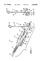
- FIG. 1 is a perspective view of an optical fiber connector and a dust cover therefor according to a presently preferred embodiment of the invention
- FIG. 2 is a perspective front view of the dust cover of FIG. 1;
- FIG. 3 is a perspective view of the connector and dust cover of FIG. 1 showing the dust cover mounted to the connector;
- FIG. 4 is a exploded cross-sectional view illustrating details of the connector and dust cover of FIG. 1;
- FIG. 5 is a cross-sectional view similar to FIG. 4, but with the connector in assembled form;
- FIG. 6 is a cross-sectional view similar to FIG. 4 and 5, but with the dust cover mounted to the connector;
- FIG. 7 is a cross-sectional view similar to FIG. 6, but with a retractable body portion of the connector in a retracted position.
- FIGS. 1-7 show an optical fiber connector and a dust cover therefor according to a presently preferred embodiment of the invention.
- the connector is generally designated by reference number 2 and includes a rear, main body portion 10 and a front, retractable body portion 12.
- Rear, main body portion 10 is adapted to be attached to the end of an optical fiber cable 6 which is preferably provided with a strain relief 8 as illustrated in FIGS. 1 and 3.
- optical fiber cable 6 is of the type which carries a plurality of optical fibers; and, in the presently described embodiment, carries two optical fibers 38, 38'.
- a portion of the cable jacket is first removed to expose end portions of the optical fibers 38, 38', which are covered by buffer layers 39, 39', respectively; and the exposed end portions of the fibers are extended into the main body portion 10 of the connector and the ends thereof are terminated by fiber termination structures 36 which include fiber optic ferrules 40 of ceramic or other material.
- fiber termination structures 36 also each include a tubular-shaped support member 41 positioned within a passageway 42 in main connector body portion 10; and a ferrule 40 is mounted to the outer end of each tubular-shaped support member so as to extend outwardly beyond the front end 43 of body portion 10.
- a spring 45 is positioned around each tubular-shaped member and extends between a U-shaped clip or positioning element 44 and an annular flange 47 on the tubular-shaped member.
- Clip 44 is dimensioned to be held by interference fit on internal wall portions 17, as illustrated in FIG. 4 where a part of clip 44 has been broken away to reveal wall portion 17.
- springs 45 normally bias the fiber termination structures 36 including the ferrules 40 to the right in FIGS. 4-7 such that the ferrules 40 are substantially fully extended out of body portion 10; however, permit the ferrules to retract inwardly slightly when pushed.
- This resilient mounting of the ferrules 40 helps to ensure proper mating of the ferrules 40 and the ends of the optical fibers carried thereby with the ferrules to and optical fibers of a mating connector.
- Main body portion 10 also includes two latching arms 14 having latching lugs 16 formed thereon for use in attaching the connector to a mating connector or the like.
- Retractable body portion 12 of connector 2 includes a generally rectangular-shaped front surface portion 18 and a skirt portion 19.
- Front surface portion 18 includes a pair of circular openings 20 positioned to be aligned with the ferrules 40 and which are of sufficient size to permit the ferrules to extend therethrough.
- Retractable portion 12 also includes a rearwardly extending post 48 which is positioned to extend into an opening 49 in main body portion 10.
- a spring 46 is positioned around post 48 and extends between rear body portion 10 and an annular flange formed on post 48 so as to normally bias the retractable body portion 12 to an extended position with respect to rear body portion 10 as shown in FIGS. 5 and 6.
- the ferrules 40 When retractable body portion 12 is in its extended position, the ferrules 40 are substantially surrounded by skirt portion 19 thereof and do not protrude through the openings 20 in surface 18, thereby providing protection for the ferrules 40 and the optical fibers carried thereby when the connector is not mated.
- the body portion 12 By pushing retractable body portion 12 rearwardly against the bias of the spring 46, however, the body portion 12 can be moved to a retracted position illustrated in FIG. 7, at which the ferrules 40 extend through the openings 20 in front surface portion 18 and are exposed for proper mating.
- FIG. 1 also illustrates a dust cover 4 according to a presently preferred embodiment of the invention for covering fiber optic ferrules 40 of connector 2 so as to protect the ferrules 40 and the optical fibers carried therein from dust or other debris when the connector 2 is not in use.
- Dust cover 4 comprises a generally rectangular-shaped base portion 26 having a size and shape to substantially cover the front surface portion 18 of retractable body portion 12 of connector 2 when the dust cover 4 is mounted to the connector 10.
- a pair of spaced protruding portions 22 extend outwardly from and are substantially perpendicular to the front surface 51 of base portion 26 and are positioned to be aligned with ferrules 40 in connector 2 when the dust cover 4 is mounted to the connector 10.
- Each protruding portion 22 is of tubular shape and includes a central axial cavity 24 extending substantially the length thereof for receiving an optical ferrule therein when the cover is mounted to the connector.
- Dust cover 4 also includes a grasping portion 30 extending substantially perpendicular from the rear surface 52 of the base portion 26 to facilitate grasping and manipulating of the dust cover during mounting and removal of the dust cover from connector 2.
- Grasping portion 30 comprises a flat, generally triangular-shaped portion, the opposite surfaces of which can easily and firmly be grasped by a user.
- Dust cover 4 is also provided with a lanyard 32 which extends from an edge of base portion 26. As shown in FIG. 3, a loop 34 formed at the free end of the lanyard 32 is adapted to encircle the cable 6 adjacent the strain relief 8 to loosely secure the dust cover 4 thereto to prevent misplacement of the cover when it is not in use.
- Protruding portions 22 of dust cover 4 are sized to extend through openings 20 in front surface portion 18 of retractable body portion 12, and the central cavities 24 thereof are sized to receive and surround the ferrules 40 therein with a slight interference fit when the dust cover is mounted to the connector.
- the grasping portion 30 of the dust cover is grasped by the user, and the protruding portions 22 of the dust cover are aligned with ferrules 40 of the connector.
- the dust cover is then pushed toward the connector thereby causing the protruding portions 22 to simultaneously enter into openings 20 in retractable portion 12 and to simultaneously surround and cover the ferrules 40.
- FIG. 6 shows dust cover 4 mounted on connector 2.
- the length of protruding portions 22 is such that ferrules 40 will extend substantially fully into the cavities 24 thereof and be substantially fully covered so as to prevent the accumulation of dust or other debris thereon.
- front surface 51 of base portion 26 of dust cover 4 engages outer surface 18 of retractable body portion 12 to thereby effectively cover openings 20 and provide further protection against contaminants entering into the connector through the openings 20.
- FIG. 7 shows the connector assembly 2 with retractable body portion 12 in its retracted position. As shown, dust cover 4 still substantially fully covers and protects the ferrules when the retractable body portion is in this position.
- dust cover 4 permits both ferrules 40 to be quickly and easily covered or uncovered simultaneously in a single operation. Also, the dust cover can be mounted to and removed from the connector without it being necessary to retract the retractable body portion 12 of the connector, thus further facilitating the procedure.
- dust cover 4 comprises a unitary, one-piece structure formed of a suitable resilient material, such as Santopren® thermoplastic rubber available from Monsanto Chemical Co., Akron, Ohio.
- a suitable resilient material such as Santopren® thermoplastic rubber available from Monsanto Chemical Co., Akron, Ohio.
- the thickness of the protruding portions 22 is such that the portions are relatively flexible so as to effectively receive the ferrules with an interference fit.
- the base portion 26 and the grasping portion 30, are preferably somewhat thicker so as to be more rigid and less deformable for most effective operation of the cover.
Abstract
Description
Claims (17)
Priority Applications (1)
| Application Number | Priority Date | Filing Date | Title |
|---|---|---|---|
| US07/876,674 US5202949A (en) | 1992-04-30 | 1992-04-30 | Dust cover for fiber optic ferrules of optical fiber connectors |
Applications Claiming Priority (1)
| Application Number | Priority Date | Filing Date | Title |
|---|---|---|---|
| US07/876,674 US5202949A (en) | 1992-04-30 | 1992-04-30 | Dust cover for fiber optic ferrules of optical fiber connectors |
Publications (1)
| Publication Number | Publication Date |
|---|---|
| US5202949A true US5202949A (en) | 1993-04-13 |
Family
ID=25368340
Family Applications (1)
| Application Number | Title | Priority Date | Filing Date |
|---|---|---|---|
| US07/876,674 Expired - Fee Related US5202949A (en) | 1992-04-30 | 1992-04-30 | Dust cover for fiber optic ferrules of optical fiber connectors |
Country Status (1)
| Country | Link |
|---|---|
| US (1) | US5202949A (en) |
Cited By (37)
| Publication number | Priority date | Publication date | Assignee | Title |
|---|---|---|---|---|
| EP0766111A1 (en) * | 1995-09-29 | 1997-04-02 | Framatome Connectors International | Optical connector and its fabrication method |
| US5712938A (en) * | 1996-05-30 | 1998-01-27 | Tai Jin Mold Mfg. Co. | Optical fiber connector |
| DE19714969C1 (en) * | 1997-04-10 | 1999-02-04 | Siemens Ag | Connector for fiber optic cable and socket part for such connector |
| US5887098A (en) * | 1997-02-27 | 1999-03-23 | Molex Incorporated | Fiber optic adapter with protective shield |
| US6108482A (en) * | 1998-01-14 | 2000-08-22 | Molex Incorporated | Fiber optic connector receptacle |
| EP1045267A1 (en) * | 1999-04-15 | 2000-10-18 | Lucent Technologies Inc. | Dust cover for protecting optical fiber sleeve housing |
| US6227717B1 (en) * | 1997-12-16 | 2001-05-08 | The Siemon Company | Dust caps for use with telecommunications adapters and connectors |
| EP1172671A1 (en) * | 2000-07-03 | 2002-01-16 | Yazaki Corporation | Protection cap for optical connector |
| EP1172672A2 (en) * | 2000-07-12 | 2002-01-16 | Molex Incorporated | Dual-function dust cover for fiber optic connector |
| US6471412B1 (en) | 2000-02-04 | 2002-10-29 | Molex Incorporated | Fiber optic connector receptacle |
| US20030002815A1 (en) * | 2001-06-29 | 2003-01-02 | Kiyoshi Tanaka | Optical fiber connector plug protecting cap |
| US6516129B2 (en) | 2001-06-28 | 2003-02-04 | Jds Uniphase Corporation | Processing protective plug insert for optical modules |
| US6547450B2 (en) | 2001-06-27 | 2003-04-15 | Fitel Usa Corp. | Quick-release dust cap for an optical plug |
| US6595696B1 (en) | 2001-03-14 | 2003-07-22 | Amphenol Corporation | Internal shutter for optical adapters |
| US6652159B2 (en) | 2001-06-28 | 2003-11-25 | International Business Machines Corporation | Enhanced optical transceiver arrangement |
| US6676301B2 (en) | 2001-06-28 | 2004-01-13 | International Business Machines Corporation | Enhanced optical coupler |
| US6688780B2 (en) | 2002-02-07 | 2004-02-10 | Amphenol Corporation | Cantilevered shutter for optical adapter |
| US20040230118A1 (en) * | 2003-02-07 | 2004-11-18 | Alfred E. Mann Institute For Biomedical Engineering At The University Of Southern Ca | Surgical drain with sensors for monitoring internal tissue condition |
| US20060239620A1 (en) * | 2003-05-02 | 2006-10-26 | Nicholas Brownjohn | Fibre optic connector |
| US20080310795A1 (en) * | 2007-06-13 | 2008-12-18 | Parkman Iii Louis Edward | Dust cap for fiber optic adapter |
| US20090016684A1 (en) * | 2004-12-13 | 2009-01-15 | Adc Telecommunications, Inc. | Service blocker device and method |
| US20090163782A1 (en) * | 2003-02-26 | 2009-06-25 | Alfred E. Mann Institute For Biomedical Engineering At The University Of Southern Californ | Implantable device with sensors for differential monitoring of internal condition |
| US20090297102A1 (en) * | 2008-05-28 | 2009-12-03 | Adc Telecommunications, Inc. | Fiber optic cable for connectorization and method |
| US20100111484A1 (en) * | 2008-10-31 | 2010-05-06 | Tyco Electronics Corporation | Fiber optic connector storage apparatus and methods for using the same |
| US20100129043A1 (en) * | 2008-11-24 | 2010-05-27 | Terry Lee Cooke | Fiber optic dust cap assembly and method |
| US20100240238A1 (en) * | 2007-10-16 | 2010-09-23 | Mitsubishi Heavy Industries, Ltd. | Connector terminal protection cap and harness assembly |
| WO2011116164A1 (en) * | 2010-03-19 | 2011-09-22 | Corning Incorporated | Fiber optic interface device with positionable cleaning cover |
| US20110229088A1 (en) * | 2010-03-19 | 2011-09-22 | Isenhour Micah C | Fiber optic interface device with positionable cleaning cover |
| US20130129302A1 (en) * | 2011-11-22 | 2013-05-23 | Avago Technologies Fiber Ip (Singapore) Pte. Ltd. | Flexible dust cover for use with a parallel optical communications module to prevent airborne matter from entering the module, and a method |
| US20140153879A1 (en) * | 2010-10-22 | 2014-06-05 | Panduit Corp. | Optical communication connector |
| WO2016041551A1 (en) * | 2014-09-16 | 2016-03-24 | HARTING Electronics GmbH | Protective cap for a plug connector housing |
| US20160204542A1 (en) * | 2015-01-08 | 2016-07-14 | Westek Electronics, Inc. | Banana plug |
| US9798091B2 (en) | 2013-01-29 | 2017-10-24 | CommScope Connectivity Belgium BVBA | Fiber optic connector with fiber end protection |
| US9885839B2 (en) | 2013-01-29 | 2018-02-06 | CommScope Connectivity Belgium BVBA | Optical fiber connection system including optical fiber alignment device with optical fiber cleaner |
| US20180131125A1 (en) * | 2016-11-07 | 2018-05-10 | Andy BAILEY | Jack caps |
| US10557996B2 (en) | 2015-09-28 | 2020-02-11 | Commscope Technologies Llc | End face protection tape for fiber optic connector; and methods |
| USRE49942E1 (en) * | 2011-10-05 | 2024-04-23 | Senko Advanced Components, Inc. | Latching connector with remote release |
Citations (2)
| Publication number | Priority date | Publication date | Assignee | Title |
|---|---|---|---|---|
| US4640575A (en) * | 1986-01-13 | 1987-02-03 | Rockwell International Corporation | Fiber optic connector cover apparatus |
| US4979792A (en) * | 1989-08-21 | 1990-12-25 | Amp Incorporated | Means for keeping keying elements with a connector assembly |
-
1992
- 1992-04-30 US US07/876,674 patent/US5202949A/en not_active Expired - Fee Related
Patent Citations (2)
| Publication number | Priority date | Publication date | Assignee | Title |
|---|---|---|---|---|
| US4640575A (en) * | 1986-01-13 | 1987-02-03 | Rockwell International Corporation | Fiber optic connector cover apparatus |
| US4979792A (en) * | 1989-08-21 | 1990-12-25 | Amp Incorporated | Means for keeping keying elements with a connector assembly |
Cited By (77)
| Publication number | Priority date | Publication date | Assignee | Title |
|---|---|---|---|---|
| FR2739458A1 (en) * | 1995-09-29 | 1997-04-04 | Framatome Connectors France | OPTICAL CONNECTOR AND ITS MANUFACTURING METHOD |
| EP0766111A1 (en) * | 1995-09-29 | 1997-04-02 | Framatome Connectors International | Optical connector and its fabrication method |
| US5712938A (en) * | 1996-05-30 | 1998-01-27 | Tai Jin Mold Mfg. Co. | Optical fiber connector |
| US5887098A (en) * | 1997-02-27 | 1999-03-23 | Molex Incorporated | Fiber optic adapter with protective shield |
| DE19714969C1 (en) * | 1997-04-10 | 1999-02-04 | Siemens Ag | Connector for fiber optic cable and socket part for such connector |
| US6101307A (en) * | 1997-04-10 | 2000-08-08 | Siemens Aktiengesellschaft | Plug for optical fiber cables and socket part for such plugs |
| US6227717B1 (en) * | 1997-12-16 | 2001-05-08 | The Siemon Company | Dust caps for use with telecommunications adapters and connectors |
| US6108482A (en) * | 1998-01-14 | 2000-08-22 | Molex Incorporated | Fiber optic connector receptacle |
| US6188825B1 (en) | 1999-04-15 | 2001-02-13 | Lucent Technologies, Inc. | Dust cover for protecting optical fiber sleeve housing |
| EP1045267A1 (en) * | 1999-04-15 | 2000-10-18 | Lucent Technologies Inc. | Dust cover for protecting optical fiber sleeve housing |
| US6471412B1 (en) | 2000-02-04 | 2002-10-29 | Molex Incorporated | Fiber optic connector receptacle |
| US6628878B2 (en) | 2000-07-03 | 2003-09-30 | Yazaki Corporation | Protection cap for optical connector |
| EP1172671A1 (en) * | 2000-07-03 | 2002-01-16 | Yazaki Corporation | Protection cap for optical connector |
| EP1172672A2 (en) * | 2000-07-12 | 2002-01-16 | Molex Incorporated | Dual-function dust cover for fiber optic connector |
| EP1172672B1 (en) * | 2000-07-12 | 2007-04-04 | Molex Incorporated | Dual-function dust cover for fiber optic connector |
| US6595696B1 (en) | 2001-03-14 | 2003-07-22 | Amphenol Corporation | Internal shutter for optical adapters |
| US6547450B2 (en) | 2001-06-27 | 2003-04-15 | Fitel Usa Corp. | Quick-release dust cap for an optical plug |
| US6652159B2 (en) | 2001-06-28 | 2003-11-25 | International Business Machines Corporation | Enhanced optical transceiver arrangement |
| US6676301B2 (en) | 2001-06-28 | 2004-01-13 | International Business Machines Corporation | Enhanced optical coupler |
| US6516129B2 (en) | 2001-06-28 | 2003-02-04 | Jds Uniphase Corporation | Processing protective plug insert for optical modules |
| US20030002815A1 (en) * | 2001-06-29 | 2003-01-02 | Kiyoshi Tanaka | Optical fiber connector plug protecting cap |
| US6736548B2 (en) * | 2001-06-29 | 2004-05-18 | Seiko Instruments Inc. | Optical fiber connector plug protecting cap |
| US6688780B2 (en) | 2002-02-07 | 2004-02-10 | Amphenol Corporation | Cantilevered shutter for optical adapter |
| US7252659B2 (en) | 2003-02-07 | 2007-08-07 | Alfred E. Mann Institute For Biomedical Engineering At The University Of Southern California | Implanted surgical drain with sensing and transmitting elements for monitoring internal tissue condition |
| US20040230118A1 (en) * | 2003-02-07 | 2004-11-18 | Alfred E. Mann Institute For Biomedical Engineering At The University Of Southern Ca | Surgical drain with sensors for monitoring internal tissue condition |
| US20040254432A1 (en) * | 2003-02-07 | 2004-12-16 | Alfred E. Mann Institute For Biomedical Engineering At The Univ. Of S. California | Surgical drain with sensors for differential monitoring of internal condition |
| US20060217684A1 (en) * | 2003-02-07 | 2006-09-28 | Alfred E. Mann Institute For Biomedical Engineering | Surgical Drain with Sensors for Monitoring Internal Tissue Condition |
| US20060217685A1 (en) * | 2003-02-07 | 2006-09-28 | Alfred E. Mann Institute For Biomedical Engineering | Surgical Drain with Sensors for Monitoring Internal Tissue Condition |
| US7419483B2 (en) | 2003-02-07 | 2008-09-02 | Alfred E. Mann Institute For Biomedical Engineering At The University Of Southern California | Surgical drain with positioning and protective features |
| US20040230132A1 (en) * | 2003-02-07 | 2004-11-18 | Alfred E. Mann Institute For Biomedical Engineering At The | Surgical drain with positioning and protective features |
| US7322971B2 (en) | 2003-02-07 | 2008-01-29 | Alfred E. Mann Institute For Biomedical Engineering At The University Of Southern California | Surgical drain with sensors for monitoring internal tissue condition by transmittance |
| US7241287B2 (en) | 2003-02-07 | 2007-07-10 | Alfred E. Mann Institute For Biomedical Engineering At The University Of Southern California | Implanted surgical drain with drain holes for monitoring internal tissue condition |
| US7244251B2 (en) | 2003-02-07 | 2007-07-17 | Alfred E. Mann Institute For Biomedical Engineering | Implanted surgical drain with multiple sensing elements for monitoring internal tissue condition |
| US20040254431A1 (en) * | 2003-02-07 | 2004-12-16 | Alfred E. Mann Institute For Biomedical Engineering At The University Of Southern Ca | Surgical drain with sensors for monitoring internal tissue condition by transmittance |
| US7264616B2 (en) | 2003-02-07 | 2007-09-04 | Alfred E. Mann Institute For Biomedical Engineering At The University Of Southern California | Method of utilizing a surgical drain with sensors for monitoring internal tissue condition |
| US20090163782A1 (en) * | 2003-02-26 | 2009-06-25 | Alfred E. Mann Institute For Biomedical Engineering At The University Of Southern Californ | Implantable device with sensors for differential monitoring of internal condition |
| US7237965B2 (en) | 2003-05-02 | 2007-07-03 | Airbus Uk Limited | Fibre optic connector |
| US20060239620A1 (en) * | 2003-05-02 | 2006-10-26 | Nicholas Brownjohn | Fibre optic connector |
| US20090016684A1 (en) * | 2004-12-13 | 2009-01-15 | Adc Telecommunications, Inc. | Service blocker device and method |
| US7756383B2 (en) * | 2004-12-13 | 2010-07-13 | Adc Telecommunications, Inc. | Service blocker device and method |
| US20080310795A1 (en) * | 2007-06-13 | 2008-12-18 | Parkman Iii Louis Edward | Dust cap for fiber optic adapter |
| US7945139B2 (en) * | 2007-06-13 | 2011-05-17 | Corning Cable Systems Llc | Dust cap for fiber optic adapter |
| US20100240238A1 (en) * | 2007-10-16 | 2010-09-23 | Mitsubishi Heavy Industries, Ltd. | Connector terminal protection cap and harness assembly |
| US8152540B2 (en) * | 2007-10-16 | 2012-04-10 | Mitsubishi Heavy Industries, Ltd. | Connector terminal protection cap and harness assembly |
| US9046658B2 (en) | 2008-05-28 | 2015-06-02 | Adc Telecommunications, Inc. | Fiber optic cable and connector assembly |
| US8391658B2 (en) | 2008-05-28 | 2013-03-05 | Adc Telecommunications, Inc. | Fiber optic cable with jacket embedded with reinforcing members |
| US9678290B2 (en) | 2008-05-28 | 2017-06-13 | Commscope Technologies Llc | Fiber optic cable assembly including a connector assembly |
| US20090297102A1 (en) * | 2008-05-28 | 2009-12-03 | Adc Telecommunications, Inc. | Fiber optic cable for connectorization and method |
| US20100111484A1 (en) * | 2008-10-31 | 2010-05-06 | Tyco Electronics Corporation | Fiber optic connector storage apparatus and methods for using the same |
| US8369677B2 (en) | 2008-10-31 | 2013-02-05 | Tyco Electronics Corporation | Fiber optic connector storage apparatus and methods for using the same |
| USRE47307E1 (en) | 2008-10-31 | 2019-03-19 | Commscope Technologies Llc | Fiber optic connector storage apparatus and methods for using the same |
| US8224144B2 (en) * | 2008-10-31 | 2012-07-17 | Tyco Electronics Corporation | Fiber optic connector storage apparatus and methods for using the same |
| US7787737B2 (en) * | 2008-11-24 | 2010-08-31 | Corning Cable Systems Llc | Fiber optic dust cap assembly and method |
| US20100129043A1 (en) * | 2008-11-24 | 2010-05-27 | Terry Lee Cooke | Fiber optic dust cap assembly and method |
| US8727636B2 (en) | 2010-03-19 | 2014-05-20 | Corning Incorporated | Fiber optic interface device with positionable cleaning cover |
| CN102834753A (en) * | 2010-03-19 | 2012-12-19 | 康宁公司 | Fiber optic interface device with positionable cleaning cover |
| US20110229088A1 (en) * | 2010-03-19 | 2011-09-22 | Isenhour Micah C | Fiber optic interface device with positionable cleaning cover |
| WO2011116164A1 (en) * | 2010-03-19 | 2011-09-22 | Corning Incorporated | Fiber optic interface device with positionable cleaning cover |
| US20160377819A1 (en) * | 2010-10-22 | 2016-12-29 | Panduit Corp. | Optical communication connector |
| US20140153879A1 (en) * | 2010-10-22 | 2014-06-05 | Panduit Corp. | Optical communication connector |
| US9638872B2 (en) * | 2010-10-22 | 2017-05-02 | Panduit Corp. | Optical communication connector |
| US9442256B2 (en) * | 2010-10-22 | 2016-09-13 | Panduit Corp. | Optical communication connector |
| USRE49942E1 (en) * | 2011-10-05 | 2024-04-23 | Senko Advanced Components, Inc. | Latching connector with remote release |
| US8849085B2 (en) * | 2011-11-22 | 2014-09-30 | Avago Technologies General Ip (Singapore) Pte. Ltd. | Flexible dust cover for use with a parallel optical communications module to prevent airborne matter from entering the module, and a method |
| US20130129302A1 (en) * | 2011-11-22 | 2013-05-23 | Avago Technologies Fiber Ip (Singapore) Pte. Ltd. | Flexible dust cover for use with a parallel optical communications module to prevent airborne matter from entering the module, and a method |
| US10578810B2 (en) | 2013-01-29 | 2020-03-03 | CommScope Connectivity Belgium BVBA | Optical fiber connection system including optical fiber alignment device with optical fiber cleaner |
| US9798091B2 (en) | 2013-01-29 | 2017-10-24 | CommScope Connectivity Belgium BVBA | Fiber optic connector with fiber end protection |
| US11668883B2 (en) | 2013-01-29 | 2023-06-06 | CommScope Connectivity Belgium BVBA | Optical fiber connection system including optical fiber alignment device with optical fiber cleaner |
| US9885839B2 (en) | 2013-01-29 | 2018-02-06 | CommScope Connectivity Belgium BVBA | Optical fiber connection system including optical fiber alignment device with optical fiber cleaner |
| US11002922B2 (en) | 2013-01-29 | 2021-05-11 | CommScope Connectivity Belgium BVBA | Optical fiber connection system including optical fiber alignment device with optical fiber cleaner |
| US9799984B2 (en) | 2014-09-16 | 2017-10-24 | HARTING Electronics GmbH | Protective cap for a plug connector housing |
| WO2016041551A1 (en) * | 2014-09-16 | 2016-03-24 | HARTING Electronics GmbH | Protective cap for a plug connector housing |
| US20160204542A1 (en) * | 2015-01-08 | 2016-07-14 | Westek Electronics, Inc. | Banana plug |
| US9761993B2 (en) * | 2015-01-08 | 2017-09-12 | Westek Electronics, Inc. | Banana plug |
| US10557996B2 (en) | 2015-09-28 | 2020-02-11 | Commscope Technologies Llc | End face protection tape for fiber optic connector; and methods |
| US11029469B2 (en) | 2015-09-28 | 2021-06-08 | Commscope Technologies Llc | End face protection tape for fiber optic connector; and methods |
| US20180131125A1 (en) * | 2016-11-07 | 2018-05-10 | Andy BAILEY | Jack caps |
Similar Documents
| Publication | Publication Date | Title |
|---|---|---|
| US5202949A (en) | Dust cover for fiber optic ferrules of optical fiber connectors | |
| US6188825B1 (en) | Dust cover for protecting optical fiber sleeve housing | |
| JP2582033B2 (en) | Connector assembly for optical fiber | |
| EP0563995B1 (en) | Optical fiber connector | |
| US6565262B2 (en) | Trigger mechanism, optical cable connector including same, and method of assembling an optical cable connector | |
| JP3105127U (en) | Optical fiber receptacle with protective shutter | |
| US4645295A (en) | Fiber optic connector | |
| KR100245143B1 (en) | Anti-snag duplex connector | |
| EP2321681B1 (en) | Fiber optic adapter with integrally molded ferrule alignment structure | |
| KR0182255B1 (en) | Connector assembly having a latching mechanism | |
| EP1514146B1 (en) | System for terminating optical fibers in a fiber optic connector | |
| US7845859B2 (en) | Ferrule assembly and methods thereof | |
| CA1308280C (en) | Duplex optical fiber connector | |
| EP0576973B1 (en) | Fiber optic connector and tool for assembling same | |
| US7695198B1 (en) | Latch protection clip for a connector | |
| US4208092A (en) | Fiber optic multi-cable pair connector | |
| EP3535614A1 (en) | Optical fiber connector with integrated installation tools | |
| EP0339876B1 (en) | Connector assembly with movable shroud protection | |
| US20160124174A1 (en) | Optical fiber furcation assembly and method | |
| US6899468B2 (en) | Optical fiber connectors | |
| US6893165B2 (en) | Optic fiber connectors and coupling sleeve | |
| US6186671B1 (en) | Optical fiber ferrule | |
| EP0836104A1 (en) | Fiber optic connector | |
| CN110799872A (en) | Optical connector and push-pull member | |
| JPH063489B2 (en) | Optical fiber connector |
Legal Events
| Date | Code | Title | Description |
|---|---|---|---|
| AS | Assignment |
Owner name: AMP INCORPORATED, PENNSYLVANIA Free format text: ASSIGNMENT OF ASSIGNORS INTEREST.;ASSIGNORS:HILEMAN, RONALD A.;SAVITSKY, WALLACE R.;REEL/FRAME:006120/0041 Effective date: 19920430 |
|
| FEPP | Fee payment procedure |
Free format text: PAYOR NUMBER ASSIGNED (ORIGINAL EVENT CODE: ASPN); ENTITY STATUS OF PATENT OWNER: LARGE ENTITY |
|
| FPAY | Fee payment |
Year of fee payment: 4 |
|
| FPAY | Fee payment |
Year of fee payment: 8 |
|
| REMI | Maintenance fee reminder mailed | ||
| LAPS | Lapse for failure to pay maintenance fees | ||
| STCH | Information on status: patent discontinuation |
Free format text: PATENT EXPIRED DUE TO NONPAYMENT OF MAINTENANCE FEES UNDER 37 CFR 1.362 |
|
| FP | Lapsed due to failure to pay maintenance fee |
Effective date: 20050413 |