US5209809A - Detacher to folder or pressure sealer shingle conveyor - Google Patents
Detacher to folder or pressure sealer shingle conveyor Download PDFInfo
- Publication number
- US5209809A US5209809A US07/868,656 US86865692A US5209809A US 5209809 A US5209809 A US 5209809A US 86865692 A US86865692 A US 86865692A US 5209809 A US5209809 A US 5209809A
- Authority
- US
- United States
- Prior art keywords
- substrate
- forms
- assembly
- recited
- detacher
- Prior art date
- Legal status (The legal status is an assumption and is not a legal conclusion. Google has not performed a legal analysis and makes no representation as to the accuracy of the status listed.)
- Expired - Lifetime
Links
Images


Classifications
-
- B—PERFORMING OPERATIONS; TRANSPORTING
- B43—WRITING OR DRAWING IMPLEMENTS; BUREAU ACCESSORIES
- B43M—BUREAU ACCESSORIES NOT OTHERWISE PROVIDED FOR
- B43M5/00—Devices for closing envelopes
- B43M5/04—Devices for closing envelopes automatic
- B43M5/047—Devices for closing envelopes automatic using pressure-sensitive adhesive
-
- Y—GENERAL TAGGING OF NEW TECHNOLOGICAL DEVELOPMENTS; GENERAL TAGGING OF CROSS-SECTIONAL TECHNOLOGIES SPANNING OVER SEVERAL SECTIONS OF THE IPC; TECHNICAL SUBJECTS COVERED BY FORMER USPC CROSS-REFERENCE ART COLLECTIONS [XRACs] AND DIGESTS
- Y10—TECHNICAL SUBJECTS COVERED BY FORMER USPC
- Y10T—TECHNICAL SUBJECTS COVERED BY FORMER US CLASSIFICATION
- Y10T156/00—Adhesive bonding and miscellaneous chemical manufacture
- Y10T156/17—Surface bonding means and/or assemblymeans with work feeding or handling means
- Y10T156/1702—For plural parts or plural areas of single part
Definitions
- printers which produce forms in continuous supply configuration cannot simply pass the forms through a conventional detacher (such as that sold by Moore Business Forms) and then directly to the sealer since detachers use integral tape delivery conveyors which vary in floor height from model to model, the side edges of the detached forms from detachers are irregular and can have a variation of up to one-half inch depending upon stock, perforations, operator skill, etc., and the detaching action itself is not completely regular, occasionally resulting in one or more of the detached forms lagging or leading the shingled stack and preventing a clean removal ("pick-off") of the form at the end of the detacher conveyor.
- a conventional detacher such as that sold by Moore Business Forms
- a method and apparatus which effect deshingling of the forms between the detacher and the sealer, as well as proper registration of the deshingled forms, so that the forms may be readily acted upon by the sealer and/or intermediate equipment.
- a distinct conveyor assembly is operatively connected between the detacher and the sealer so that the detached, shingled forms may be cleanly fed, in registration, directly to a sealer, or first to a hopper and then to a folder before being fed to the sealer.
- a method of handling business forms having or formable into multiple plies with lines of adhesive between the plies, and originally in a continuous supply configuration comprises the steps of sequentially and continuously: (a) detaching individual forms from the continuous supply of forms while conveying them in a first direction, to form shingled forms having irregularly positioned side edges moving in the first direction; (b) deshingling the forms, so that they are spaced from each other in the first direction; (c) registering the deshingled forms; and (d) acting on the adhesive lines of the forms to effect sealing of the plies of the forms together.
- Steps (b) and (c) are preferably accomplished simultaneously while conveying the forms in the first direction.
- the individual forms may be folded to form the multiple plies between steps (c) and (d), and in such a situation preferably are fed into the top of a hopper and withdrawn from the bottom of the hopper, prior to folding.
- Registration may be accomplished by conveying the forms against a single side aligning structure, or funneling them into contact with dual side aligning structures.
- the deshingling action is accomplished by conveying the forms in the first direction at a much greater speed than the conveying of the shingled forms, e.g. at least about ten times greater speed.
- apparatus for accomplishing a method as set forth above may take one of two configurations.
- a conveyor belt is angled with respect to a substrate, and has a leading end having a nip roller disposed thereover, the leading end of the conveyor belt grasping each shingled form in turn and conveying it at high speed against an edge aligning structure, and then feeding it directly to the sealer.
- the conveyor belt is mounted in the central portion of the substrate with a spring pressed roller thereover, and a plurality of gravity biased rollers, each individual form being conveyed past side edges funneling toward each other and ultimately forming parallel aligning edge structures which guide the forms into the top of the hopper.
- the forms are withdrawn from the bottom of the hopper to a folder, and then fed to a sealer.
- the invention also contemplates a distinct conveyor assembly for operatively connecting a detacher to a sealer for transforming continuous configuration business forms into sealed individual business form mailers.
- the assembly comprises: a substrate; conveying means mounted in association with the substrate for conveying forms along the substrate in a first direction; means for registering the forms during conveyance in the first direction; and means for releasably mounting the substrate between a detacher and a sealer.
- the conveying and registering means may take the form of either of the two configurations described above.
- FIG. 1 is a top plan view, with the hold-down mechanisms removed for clarity of illustration, of a first exemplary apparatus according to the present invention
- FIG. 2 is a detail side view, partly in cross section and partly in elevation, of the conveyor component according to the invention which is associated with the apparatus of FIG. 1;
- FIG. 3 is a top perspective view of the apparatus of FIGS. 1 and 2;
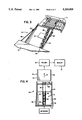
- FIG. 4 is a top plan view of a second embodiment of apparatus according to the present invention.
- FIG. 5 is a side view of the conveyor component of the apparatus of FIG. 4.
- FIG. 6 is a side perspective view of the embodiment of FIGS. 4 and 5.
- An apparatus 10 in the first embodiment of the invention illustrated in FIGS. 1 through 3 comprises a distinct conveyor assembly for operatively connecting a detacher 11 to a sealer 12 for transforming continuous configuration business forms into sealed individual business form constructions (typically mailers).
- the detacher 11 is a conventional detacher, such as sold by Moore Business Forms, and the sealer 12 a conventional sealer.
- the sealer 12 is a pressure sealer such as shown in said U.S. patent application Ser. No. 07/417,775, filed Oct. 6, 1989, but it also may be a conventional heat sealing type sealer.
- the detacher 11 has a conveyor assembly 14 associated therewith with a plurality of spaced conveyor tapes 15 movable over a substrate 16 on which forms 18 are conveyed in a first direction 19. Note that the individual forms 18 are detached when associated with the detaching conveyor 14, and are shingled, and that the side edges thereof are irregular. This is a necessary result of operation of most conventional detachers.
- the forms are fed in the first direction 19 by the detacher conveying means 14 at a first, relatively slow speed, e.g. about ten feet per minute.
- the conveyor assembly 10 includes a conveyor belt 20 operatively associated with a substrate 21 and a registering means comprising an upright side edge structure 22 along one side of the substrate 21, the edge structure 22 being essentially parallel to the first direction 19.
- the conveyor belt 20 itself extends at an angle with respect to the first direction 19, moving toward the edge structure 22 in the general direction 19.
- Such a conveying structure is known per se in the art (e.g. see U.S. Pat. No. 2,190,413).
- a nip roller 23 is mounted by a shaft 24 to hold each form 18 in contact with the front end of the conveyor belt 20.
- the nip roller 23 is mounted past the leading edge 25 of the substrate 21, preferably over the front roller 26 for the conveyor belt 20, the front roller 26 also being mounted in front of the leading edge 25 of the substrate 21.
- a rear roller 27 for the conveyor belt 20 is powered, as by a conventional electric motor 28.
- the conveyor belt 20 is powered by the motor 28 at a much higher speed than the speed of movement of the shingled forms 18 on the detacher conveyor 14.
- the speed of the conveyor 20 in order to insure proper deshingling action is at least about ten times greater than the speed of the shingled forms, e.g. about 200 feet per minute.
- the assembly 10 also comprises hold-down elements 30 disposed over the conveyor 20 (not seen in FIG. 1 but seen in FIGS. 2 and 3), comprising balls 31 biased by their own weight in each of cages 33 into contact with the top of the belt 20 to hold the form thereat.
- the biasing force can be changed by changing the weight (density) of the material of which the balls are made (e.g. glass, plastic, steel, etc.).
- the forms 18 when shingled have only a slight overlap, which overlap has been exaggerated in FIG. 1 for clarity of illustration.
- the forms 18 have a dimension in the first direction 19 of about five and one-half inches, the shingle overlap will be slightly over one-half an inch (e.g. about one-tenth of the dimension in direction 19).
- Nipping rollers are provided in association with the detacher conveyor 14 at a horizontal spacing of just greater than the form 18 dimension in the direction 19, e.g. just over five and one-half inches in the special case set forth above.
- the forms 18 either may initially be multi-ply forms with adhesive (e.g. pressure sensitive adhesive) lines between them, or may be formable into multiply forms, e.g. having adhesive lines on the top and/or bottom thereof and then once folded having a multi-ply configuration.
- the conveyor assembly 10 is releasably mounted between the detacher 11 and the sealer 12, e.g. by support arms 36 extending from the sealer 12 and connected at one end thereof to the sealer 12 and at the other end thereof to the substrate 21 (e.g. through a threaded nut 36' thereon).
- the substrate 20 is pivotally mounted at its second end 37, opposite its first end 25, to the sealer 12, as are the ends of the rods 36 adjacent the sealer 12. In this way, by adjusting the length of the arms 36, the height of the leading edge 25 of the substrate can be adjusted to accommodate detachers 11 having different heights of the conveyor discharge 14 thereof.
- the detacher 11 detaches continuous supply configuration of business forms to form shingled forms 18 having irregularly positioned side edges while they are moving in the first direction 19.
- the leading edge of the front shingled form 18 passes into contact with the conveyor belt 20 and nip roller 23, it is immediately conveyed at a much higher speed--e.g. at least about ten times faster--and during conveyance is held in contact with the conveyor 20 by the weight biased balls 31.
- each form 18 is in turn automatically moved so that the left side edge thereof (when viewing FIG. 1) is registered with the alignment edge 22, and therefore a single form 18 is fed with desired registration directly into the pressure sealer 12.
- the conveyor has been designed to cooperate with a folder 40 which is disposed before the sealer 12 to fold the forms before they are fed to the sealer 12, and preferably includes a hopper 41 having side edges 42 thereof. Forms are bed by the conveyor assembly 44 into the top of the hopper 41 (which is per se conventional), and then are fed from the bottom of the hopper 41 to the folder 40 (as is also conventional).
- the folder 40 can be any conventional type, such a Moore Business Forms 8158 folder.
- the distinct conveyor 44 of the FIGS. 4 through 6 embodiment has a substrate 45, and at the leading edge thereof--adjacent the detacher 11--has a spring pressed roller 46 mounted for rotation about a horizontal axis defined by rod 47, the rod 47 being perpendicular to the first direction 19.
- a spring pressed roller 46 mounted for rotation about a horizontal axis defined by rod 47, the rod 47 being perpendicular to the first direction 19.
- the rollers 46, 48 are disposed above a conveyor belt 50 moving over the substrate 45.
- the conveyor belt 50 is essentially aligned with the first direction 19, and disposed at the approximate center of the substrate 45 in a horizontal dimension perpendicular to the first direction 19.
- Assembly 51 includes the gravity or spring biased rollers 52, the rollers 52 being in alignment and mounted by side arms 53, and pivotally disposed due to the pivotal connection of the arms 53 to the shaft 54.
- edge structures 55 there are upright side edge structures 55 on opposite sides of the substrate 45. As seen most clearly in FIG. 4, the side edges 55 originally funnel (taper) inward slightly, before becoming parallel and being aligned with the first direction 19 (past the rod 54, just prior to the hopper 41).
- the edge structures 55 preferably are mounted in a conventional manner so that one or both of them is movable with respect to the substrate 45 accommodate forms of different width.
- the conveyor belt 50 has a leading roller 58 and a powered roller 59, the roller 59 being powered by an electric motor 60 or the like.
- the motor 60 powers the conveyor 50 at a speed much greater (e.g. at least about ten times greater) than the speed of conveyance of the forms 18 from the detacher 11 discharge conveyor.
- the shingled forms 18 from the detacher 11 pass so that the leading edges thereof move one at a time to the leading portion of the conveyor belt 50, adjacent the leading spring pressed roller 46.
- the leading edge of a form is grasped, it is immediately and quickly conveyed in the first direction 19 at high speed, a deshingling action being effected.
- the gravity or spring biased roller assembly 51 holds the forms in contact with the conveyor 50, as the edges thereof are registered by the side edge structures 55, the individual forms passing past the discharge spring biased roller 48 into the top of the hopper 41. From the bottom of the hopper 41 they are withdrawn by the folder 40, folded, and fed to the sealer 12.
- the distinct conveyor assembly 44--either with or without the hopper 41-- is mounted as a separate support structure between the folder 40 and the detacher 11 or between the hopper 41 and the detacher 11, as the case may be. It has its own support, which may be adjustable to accommodate different heights of the detacher 11 discharge conveyor. Any of a wide variety of conventional mechanisms can be utilized to adjust the height of the substrate 45.
Abstract
Description
Claims (13)
Priority Applications (1)
| Application Number | Priority Date | Filing Date | Title |
|---|---|---|---|
| US07/868,656 US5209809A (en) | 1990-10-26 | 1992-04-15 | Detacher to folder or pressure sealer shingle conveyor |
Applications Claiming Priority (2)
| Application Number | Priority Date | Filing Date | Title |
|---|---|---|---|
| US07/604,858 US5139597A (en) | 1990-10-26 | 1990-10-26 | Detacher to folder or pressure sealer shingle conveyor |
| US07/868,656 US5209809A (en) | 1990-10-26 | 1992-04-15 | Detacher to folder or pressure sealer shingle conveyor |
Related Parent Applications (1)
| Application Number | Title | Priority Date | Filing Date |
|---|---|---|---|
| US07/604,858 Division US5139597A (en) | 1990-10-26 | 1990-10-26 | Detacher to folder or pressure sealer shingle conveyor |
Publications (1)
| Publication Number | Publication Date |
|---|---|
| US5209809A true US5209809A (en) | 1993-05-11 |
Family
ID=27084785
Family Applications (1)
| Application Number | Title | Priority Date | Filing Date |
|---|---|---|---|
| US07/868,656 Expired - Lifetime US5209809A (en) | 1990-10-26 | 1992-04-15 | Detacher to folder or pressure sealer shingle conveyor |
Country Status (1)
| Country | Link |
|---|---|
| US (1) | US5209809A (en) |
Cited By (16)
| Publication number | Priority date | Publication date | Assignee | Title |
|---|---|---|---|---|
| US5464142A (en) * | 1994-01-03 | 1995-11-07 | Pitney Bowes Inc. | Web bursting machine |
| US5887411A (en) * | 1996-12-04 | 1999-03-30 | Privatizer Systems, Inc. | Apparatus and method for positioning a number of non-transparent enclosure sheets in a document security apparatus |
| US5934045A (en) * | 1996-12-04 | 1999-08-10 | Privatizer Systems, Inc. | Method for providing confidentiality to a facsimile transmission having information associated with a first page of the transmission printed on a first enclosure sheet |
| US5937619A (en) * | 1996-12-04 | 1999-08-17 | Privatizer Systems Incorporated | Apparatus and method for sealing an envelope having a first lateral side and a second lateral side in a document security apparatus |
| US5941048A (en) * | 1996-12-04 | 1999-08-24 | Privatizer Systems, Inc | Apparatus and method of sealing an envelope in a document security apparatus |
| US5946889A (en) * | 1996-12-04 | 1999-09-07 | Privatizer Systems, Inc | Apparatus and method for enclosing a confidential sheet between a first enclosure sheet and a second enclosure sheet within a document security apparatus |
| US5951805A (en) * | 1997-10-02 | 1999-09-14 | Nonis; Vittorino | Method and apparatus for coating a decorative workpiece |
| US5956930A (en) * | 1996-12-04 | 1999-09-28 | Privatizer Systems, Inc. | Apparatus and method of forming an envelope in a document security apparatus |
| US5979148A (en) * | 1996-12-04 | 1999-11-09 | Privatizer Systems, Inc. | Apparatus and method for sealing an envelope in a document security apparatus having a sealing roller with a sealing ridge attached thereto |
| US5996317A (en) * | 1996-12-04 | 1999-12-07 | Privatizer Systems, Inc. | Method for providing confidentiality to a facsimile transmission having a non-printed back enclosure sheet |
| US6076336A (en) * | 1996-12-04 | 2000-06-20 | Privatizer Systems, Inc. | Apparatus and method for advancing a confidential sheet into a pocket defined by a number of enclosure sheets |
| US6206965B1 (en) | 1997-10-02 | 2001-03-27 | Angelo Rao | Apparatus for coating a decorative workpiece |
| US6592668B2 (en) | 1997-10-02 | 2003-07-15 | Angelo Rao | Apparatus for coating a decorative workpiece |
| US6745694B1 (en) * | 2001-06-15 | 2004-06-08 | Perkinelmer, Inc. | Method and apparatus for a slipsheet removal system |
| US9126761B1 (en) * | 2014-10-27 | 2015-09-08 | Xerox Corporation | Variable guide system for shingling in-store adhesive signage |
| US9624062B1 (en) | 2015-11-10 | 2017-04-18 | Xerox Corporation | Multi-position collation system with retracting guides including pre-compiler |
Citations (7)
| Publication number | Priority date | Publication date | Assignee | Title |
|---|---|---|---|---|
| US2190413A (en) * | 1938-05-02 | 1940-02-13 | Davidson Mfg Corp | Folding machine |
| US3962848A (en) * | 1975-03-31 | 1976-06-15 | Charles William Hankins | Envelope flap processing apparatus |
| US4318322A (en) * | 1976-07-22 | 1982-03-09 | Mail-Ex Corporation | Envelope cutter apparatus |
| US4426073A (en) * | 1980-02-27 | 1984-01-17 | Ricoh Company, Ltd. | Apparatus for aligning a paper sheet with a reference line |
| US4818332A (en) * | 1983-09-29 | 1989-04-04 | Moore Business Forms, Inc. | Business form sealer/conveyor |
| EP0426364A2 (en) * | 1989-10-26 | 1991-05-08 | Moore Business Forms, Inc. | Edge sealer for multi-ply business forms |
| US5039086A (en) * | 1988-09-02 | 1991-08-13 | Hitachi, Ltd. | Method and apparatus for adjusting posture of sheets |
-
1992
- 1992-04-15 US US07/868,656 patent/US5209809A/en not_active Expired - Lifetime
Patent Citations (7)
| Publication number | Priority date | Publication date | Assignee | Title |
|---|---|---|---|---|
| US2190413A (en) * | 1938-05-02 | 1940-02-13 | Davidson Mfg Corp | Folding machine |
| US3962848A (en) * | 1975-03-31 | 1976-06-15 | Charles William Hankins | Envelope flap processing apparatus |
| US4318322A (en) * | 1976-07-22 | 1982-03-09 | Mail-Ex Corporation | Envelope cutter apparatus |
| US4426073A (en) * | 1980-02-27 | 1984-01-17 | Ricoh Company, Ltd. | Apparatus for aligning a paper sheet with a reference line |
| US4818332A (en) * | 1983-09-29 | 1989-04-04 | Moore Business Forms, Inc. | Business form sealer/conveyor |
| US5039086A (en) * | 1988-09-02 | 1991-08-13 | Hitachi, Ltd. | Method and apparatus for adjusting posture of sheets |
| EP0426364A2 (en) * | 1989-10-26 | 1991-05-08 | Moore Business Forms, Inc. | Edge sealer for multi-ply business forms |
Cited By (18)
| Publication number | Priority date | Publication date | Assignee | Title |
|---|---|---|---|---|
| US5464142A (en) * | 1994-01-03 | 1995-11-07 | Pitney Bowes Inc. | Web bursting machine |
| US5979148A (en) * | 1996-12-04 | 1999-11-09 | Privatizer Systems, Inc. | Apparatus and method for sealing an envelope in a document security apparatus having a sealing roller with a sealing ridge attached thereto |
| US5946889A (en) * | 1996-12-04 | 1999-09-07 | Privatizer Systems, Inc | Apparatus and method for enclosing a confidential sheet between a first enclosure sheet and a second enclosure sheet within a document security apparatus |
| US5996317A (en) * | 1996-12-04 | 1999-12-07 | Privatizer Systems, Inc. | Method for providing confidentiality to a facsimile transmission having a non-printed back enclosure sheet |
| US5941048A (en) * | 1996-12-04 | 1999-08-24 | Privatizer Systems, Inc | Apparatus and method of sealing an envelope in a document security apparatus |
| US6076336A (en) * | 1996-12-04 | 2000-06-20 | Privatizer Systems, Inc. | Apparatus and method for advancing a confidential sheet into a pocket defined by a number of enclosure sheets |
| US5934045A (en) * | 1996-12-04 | 1999-08-10 | Privatizer Systems, Inc. | Method for providing confidentiality to a facsimile transmission having information associated with a first page of the transmission printed on a first enclosure sheet |
| US5956930A (en) * | 1996-12-04 | 1999-09-28 | Privatizer Systems, Inc. | Apparatus and method of forming an envelope in a document security apparatus |
| US5887411A (en) * | 1996-12-04 | 1999-03-30 | Privatizer Systems, Inc. | Apparatus and method for positioning a number of non-transparent enclosure sheets in a document security apparatus |
| US5937619A (en) * | 1996-12-04 | 1999-08-17 | Privatizer Systems Incorporated | Apparatus and method for sealing an envelope having a first lateral side and a second lateral side in a document security apparatus |
| US5951805A (en) * | 1997-10-02 | 1999-09-14 | Nonis; Vittorino | Method and apparatus for coating a decorative workpiece |
| US6206965B1 (en) | 1997-10-02 | 2001-03-27 | Angelo Rao | Apparatus for coating a decorative workpiece |
| US6592668B2 (en) | 1997-10-02 | 2003-07-15 | Angelo Rao | Apparatus for coating a decorative workpiece |
| US20040033314A1 (en) * | 1997-10-02 | 2004-02-19 | Angelo Rao | Method and apparatus for coating a decorative workpiece |
| US7851386B2 (en) | 1997-10-02 | 2010-12-14 | Lido Wall Systems Inc. | Method and apparatus for coating a decorative workpiece |
| US6745694B1 (en) * | 2001-06-15 | 2004-06-08 | Perkinelmer, Inc. | Method and apparatus for a slipsheet removal system |
| US9126761B1 (en) * | 2014-10-27 | 2015-09-08 | Xerox Corporation | Variable guide system for shingling in-store adhesive signage |
| US9624062B1 (en) | 2015-11-10 | 2017-04-18 | Xerox Corporation | Multi-position collation system with retracting guides including pre-compiler |
Similar Documents
| Publication | Publication Date | Title |
|---|---|---|
| US5209809A (en) | Detacher to folder or pressure sealer shingle conveyor | |
| AU2009288644A1 (en) | Conveying apparatus for envelopes and related methods | |
| CA2099267A1 (en) | Paper sheet feeding apparatus | |
| EP0539037B1 (en) | Stacked table top pressure sealer system | |
| GB1561761A (en) | Sheet feeding | |
| US5265731A (en) | Job separator | |
| EP0773901B1 (en) | High capacity stacker/separating device | |
| US5876555A (en) | Apparatus and method for applying a label to a package | |
| JPH0776059B2 (en) | Sheet transport device | |
| US5139597A (en) | Detacher to folder or pressure sealer shingle conveyor | |
| US5695186A (en) | Apparatus and method for collating random arrays of sheets to ordered stacks | |
| US5178383A (en) | Method of separating sheets | |
| US5098511A (en) | Flexible guide for folded, moistened documents | |
| US5025609A (en) | Sheet separator device | |
| NZ247153A (en) | Conveyor assembly for business forms: forms registered as they move along the substrate | |
| EP3489911B1 (en) | Device for franking flat mail items transported individually or from a stack on a processing line | |
| US5516256A (en) | Vertical accumulator/stacker | |
| JPS59102761A (en) | Paper handling device | |
| GB2209738A (en) | Folding and nesting paper sheets | |
| JP3132907B2 (en) | Carrier unloading conveyor | |
| JPH042930Y2 (en) | ||
| JP2657264B2 (en) | Single-wafer sorting device | |
| JP2552489B2 (en) | Stacked sheet unloading device | |
| JP3511319B2 (en) | Slitter output device | |
| JPH038659Y2 (en) |
Legal Events
| Date | Code | Title | Description |
|---|---|---|---|
| STCF | Information on status: patent grant |
Free format text: PATENTED CASE |
|
| FPAY | Fee payment |
Year of fee payment: 4 |
|
| FEPP | Fee payment procedure |
Free format text: PAYOR NUMBER ASSIGNED (ORIGINAL EVENT CODE: ASPN); ENTITY STATUS OF PATENT OWNER: LARGE ENTITY |
|
| FPAY | Fee payment |
Year of fee payment: 8 |
|
| AS | Assignment |
Owner name: CITICORP USA, INC., DELAWARE Free format text: SECURITY AGREEMENT;ASSIGNOR:MOORE NORTH AMERICA, INC.;REEL/FRAME:013211/0296 Effective date: 20020802 |
|
| AS | Assignment |
Owner name: MOORE NORTH AMERICA, INC., CANADA Free format text: CHANGE OF NAME;ASSIGNOR:MOORE U.S.A. INC.;REEL/FRAME:014090/0607 Effective date: 19980915 Owner name: MOORE NORTH AMERICA, INC., ILLINOIS Free format text: PATENT RELEASE;ASSIGNOR:CITICORP USA, INC.;REEL/FRAME:014083/0906 Effective date: 20030514 Owner name: MOORE U.S.A. INC., CANADA Free format text: CHANGE OF NAME;ASSIGNOR:MOORE BUSINESS FORMS, INC.;REEL/FRAME:014097/0159 Effective date: 19961104 |
|
| AS | Assignment |
Owner name: CITICORP NORTH AMERICA, INC., NEW YORK Free format text: SECURITY AGREEMENT;ASSIGNOR:MOORE NORTH AMERICA, INC.;REEL/FRAME:014108/0136 Effective date: 20030515 |
|
| FPAY | Fee payment |
Year of fee payment: 12 |
|
| FEPP | Fee payment procedure |
Free format text: PAYOR NUMBER ASSIGNED (ORIGINAL EVENT CODE: ASPN); ENTITY STATUS OF PATENT OWNER: LARGE ENTITY Free format text: PAYER NUMBER DE-ASSIGNED (ORIGINAL EVENT CODE: RMPN); ENTITY STATUS OF PATENT OWNER: LARGE ENTITY |