US5221201A - Vertical heat treatment apparatus - Google Patents
Vertical heat treatment apparatus Download PDFInfo
- Publication number
- US5221201A US5221201A US07/734,784 US73478491A US5221201A US 5221201 A US5221201 A US 5221201A US 73478491 A US73478491 A US 73478491A US 5221201 A US5221201 A US 5221201A
- Authority
- US
- United States
- Prior art keywords
- air
- substrates
- heat treatment
- vertical heat
- clean
- Prior art date
- Legal status (The legal status is an assumption and is not a legal conclusion. Google has not performed a legal analysis and makes no representation as to the accuracy of the status listed.)
- Expired - Lifetime
Links
- 238000010438 heat treatment Methods 0.000 title claims abstract description 64
- 239000000758 substrate Substances 0.000 claims abstract description 86
- 239000000428 dust Substances 0.000 claims description 6
- 235000012431 wafers Nutrition 0.000 abstract description 64
- 229910052751 metal Inorganic materials 0.000 description 7
- 239000002184 metal Substances 0.000 description 7
- 239000004065 semiconductor Substances 0.000 description 7
- 230000007246 mechanism Effects 0.000 description 6
- 238000005192 partition Methods 0.000 description 6
- 238000012423 maintenance Methods 0.000 description 3
- 238000000034 method Methods 0.000 description 3
- 230000008569 process Effects 0.000 description 3
- VYPSYNLAJGMNEJ-UHFFFAOYSA-N Silicium dioxide Chemical compound O=[Si]=O VYPSYNLAJGMNEJ-UHFFFAOYSA-N 0.000 description 2
- 238000004891 communication Methods 0.000 description 2
- 238000004519 manufacturing process Methods 0.000 description 2
- 239000000463 material Substances 0.000 description 2
- 239000011347 resin Substances 0.000 description 2
- 229920005989 resin Polymers 0.000 description 2
- 229910001220 stainless steel Inorganic materials 0.000 description 2
- 239000010935 stainless steel Substances 0.000 description 2
- 230000009471 action Effects 0.000 description 1
- 229910052782 aluminium Inorganic materials 0.000 description 1
- XAGFODPZIPBFFR-UHFFFAOYSA-N aluminium Chemical compound [Al] XAGFODPZIPBFFR-UHFFFAOYSA-N 0.000 description 1
- 230000015572 biosynthetic process Effects 0.000 description 1
- 238000007664 blowing Methods 0.000 description 1
- 238000004140 cleaning Methods 0.000 description 1
- 230000000694 effects Effects 0.000 description 1
- 238000012986 modification Methods 0.000 description 1
- 230000004048 modification Effects 0.000 description 1
- 230000000149 penetrating effect Effects 0.000 description 1
- 238000011045 prefiltration Methods 0.000 description 1
- 230000000717 retained effect Effects 0.000 description 1
- 238000012360 testing method Methods 0.000 description 1
Images


Classifications
-
- H—ELECTRICITY
- H01—ELECTRIC ELEMENTS
- H01L—SEMICONDUCTOR DEVICES NOT COVERED BY CLASS H10
- H01L21/00—Processes or apparatus adapted for the manufacture or treatment of semiconductor or solid state devices or of parts thereof
- H01L21/02—Manufacture or treatment of semiconductor devices or of parts thereof
- H01L21/04—Manufacture or treatment of semiconductor devices or of parts thereof the devices having at least one potential-jump barrier or surface barrier, e.g. PN junction, depletion layer or carrier concentration layer
- H01L21/34—Manufacture or treatment of semiconductor devices or of parts thereof the devices having at least one potential-jump barrier or surface barrier, e.g. PN junction, depletion layer or carrier concentration layer the devices having semiconductor bodies not provided for in groups H01L21/0405, H01L21/0445, H01L21/06, H01L21/16 and H01L21/18 with or without impurities, e.g. doping materials
- H01L21/46—Treatment of semiconductor bodies using processes or apparatus not provided for in groups H01L21/428
-
- F—MECHANICAL ENGINEERING; LIGHTING; HEATING; WEAPONS; BLASTING
- F27—FURNACES; KILNS; OVENS; RETORTS
- F27B—FURNACES, KILNS, OVENS, OR RETORTS IN GENERAL; OPEN SINTERING OR LIKE APPARATUS
- F27B17/00—Furnaces of a kind not covered by any preceding group
- F27B17/0016—Chamber type furnaces
- F27B17/0025—Especially adapted for treating semiconductor wafers
-
- C—CHEMISTRY; METALLURGY
- C30—CRYSTAL GROWTH
- C30B—SINGLE-CRYSTAL GROWTH; UNIDIRECTIONAL SOLIDIFICATION OF EUTECTIC MATERIAL OR UNIDIRECTIONAL DEMIXING OF EUTECTOID MATERIAL; REFINING BY ZONE-MELTING OF MATERIAL; PRODUCTION OF A HOMOGENEOUS POLYCRYSTALLINE MATERIAL WITH DEFINED STRUCTURE; SINGLE CRYSTALS OR HOMOGENEOUS POLYCRYSTALLINE MATERIAL WITH DEFINED STRUCTURE; AFTER-TREATMENT OF SINGLE CRYSTALS OR A HOMOGENEOUS POLYCRYSTALLINE MATERIAL WITH DEFINED STRUCTURE; APPARATUS THEREFOR
- C30B31/00—Diffusion or doping processes for single crystals or homogeneous polycrystalline material with defined structure; Apparatus therefor
- C30B31/06—Diffusion or doping processes for single crystals or homogeneous polycrystalline material with defined structure; Apparatus therefor by contacting with diffusion material in the gaseous state
- C30B31/10—Reaction chambers; Selection of materials therefor
- C30B31/103—Mechanisms for moving either the charge or heater
-
- Y—GENERAL TAGGING OF NEW TECHNOLOGICAL DEVELOPMENTS; GENERAL TAGGING OF CROSS-SECTIONAL TECHNOLOGIES SPANNING OVER SEVERAL SECTIONS OF THE IPC; TECHNICAL SUBJECTS COVERED BY FORMER USPC CROSS-REFERENCE ART COLLECTIONS [XRACs] AND DIGESTS
- Y10—TECHNICAL SUBJECTS COVERED BY FORMER USPC
- Y10S—TECHNICAL SUBJECTS COVERED BY FORMER USPC CROSS-REFERENCE ART COLLECTIONS [XRACs] AND DIGESTS
- Y10S414/00—Material or article handling
- Y10S414/135—Associated with semiconductor wafer handling
- Y10S414/137—Associated with semiconductor wafer handling including means for charging or discharging wafer cassette
-
- Y—GENERAL TAGGING OF NEW TECHNOLOGICAL DEVELOPMENTS; GENERAL TAGGING OF CROSS-SECTIONAL TECHNOLOGIES SPANNING OVER SEVERAL SECTIONS OF THE IPC; TECHNICAL SUBJECTS COVERED BY FORMER USPC CROSS-REFERENCE ART COLLECTIONS [XRACs] AND DIGESTS
- Y10—TECHNICAL SUBJECTS COVERED BY FORMER USPC
- Y10S—TECHNICAL SUBJECTS COVERED BY FORMER USPC CROSS-REFERENCE ART COLLECTIONS [XRACs] AND DIGESTS
- Y10S414/00—Material or article handling
- Y10S414/135—Associated with semiconductor wafer handling
- Y10S414/14—Wafer cassette transporting
Definitions
- This invention relates to a vertical heat treatment apparatus used for manufacturing semiconductors.
- Japanese Laid-open Patent Application Publications No. 61-111524 and No. 62-146265 and Japanese Laid-open Utility Model Publication No. 62-8633 disclose apparatuses for making clean air flow sidewise onto wafers unloaded from a vertical heat treatment furnace.
- Japanese Laid-open Patent Application Publication No. 62-36817 discloses an apparatus for making air flow downward onto wafers unloaded from a horizontal heat treatment furnace.
- Japanese laid-open Utility Model Application No. 64-26833 discloses an apparatus for making air side-flow at the unloading position of a horizontal heat treatment furnace.
- air supplied by a motor fan or the like is cleaned by passing through a filter and is made to flow onto wafers.
- the object of this invention is to provide a vertical heat treatment apparatus in which loads exerted on a fan are reduced by improving a duct for supplying air to the fan such that air is kept clean at an unloading position.
- a vertical heat treatment apparatus which comprises a casing provided with a vertical treatment furnace, substrate holding means also housed in the casing for holding substrates to be heat-treated in the vertical heat-treatment furnace, substrate supporting means for supporting substrates, loading/unloading means for putting the substrate in and taking the same out of the vertical heat treatment furnace, transmitting means for transporting the substrates between the substrate holding means and the substrate supporting means, clean air supplying means for sideways supplying clean air to the substrates supported by the substrate supporting means when the loading/unloading means is at an unloading position, the clean air supplying means being provided with an air filter disposed opposed to the substrate supporting means, and a duct for conducting air into a clean room at a pressure higher than that in the casing into the clean air supplying means.
- air is introduced from the clean room, whose pressure is set at a value higher (that is, a positive pressure) than the pressure at the unloading position in the casing, into the casing via the duct and the air filter.
- This arrangement easily allows air to flow from the clean room at a higher pressure into the casing at a lower pressure. Clean air flows sidewise onto the substrates disposed at the unloading position such that excessive loads are not applied to the blower fan.
- the air conducting duct can be set in the bottom portion of the casing in which various devices are housed, and thus the duct can be provided without increasing the setting space.
- FIG. 1 is a lateral view, with part thereof cross-sectioned, of an embodiment of a vertical heat treatment apparatus according to this invention
- FIG. 2 is a perspective view showing the structure of an unloading room of the vertical heat treatment apparatus
- FIG. 3 is a schematic view of a first embodiment of a clean module according to this invention.
- FIG. 4 is a schematic view of a second embodiment of a clean module according to this invention.
- FIG. 5 is a schematic view of a third embodiment of a clean module according to this invention.
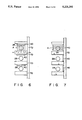
- FIG. 6 is a side view of a first embodiment of a horizontal multi-stage type furnace to which the clean modules according to this invention are applied.
- FIG. 7 is a side view of a second embodiment of a horizontal multi-stage type furnace to which the clean modules according to this invention are applied.
- a vertical heat treatment apparatus 1 is installed in a utility zone 3 disposed adjacent a clean room 2 for manufacturing semiconductors.
- the floor of the clean room 2 is formed with a net 4 for passing dust or the like.
- Air communication between the clean room 2 and the utility zone 3 is interrupted by a vertical partition wall 5.
- the front portion of the vertical heat treatment apparatus 1 communicates with the clean room 2 through an opening formed in the partition wall 5.
- the vertical heat treatment apparatus 1 has a casing 6, the interior of which is divided by a partition plate 7 into a loading room 8 and an unloading room 9, and a heat treatment furnace 10 is mounted in the loading room 8.
- a reaction tube 11 made of material such as quartz glass on which a heat treatment gas is hard to react and which shows high heat resistance. Wound around the reaction tube 11 is a coiled heater 12 for heating the interior of the reaction tube 11 to a required temperature, for example, which is selected among 600° to 1,200° C., in a spaced relation from the tube 11 at a predetermined distance so that the heater 12 is not in contact with the tube 11.
- the reaction tube 11 is connected to a gas source by means of a gas supplying pipe (not shown).
- an air exhaust pipe 13 On the upper portion of the reaction tube 11 is connected an air exhaust pipe 13 which is connected to a vacuum pump (not shown) which reduces the pressure in the reaction tube 11 to a predetermined level and exhausts a heat treatment gas.
- a boat elevator 14 In the unloading room 9 are provided a boat elevator 14, a transportation robot 15 and a cassette holding unit 16.
- the boat elevator 14 comprises a wafer boat 17 which receives as many number of substrates (for example, 100 to 150 semiconductor wafers 28) as can be heat-treated in the reaction tube 11 at a time so as to be arranged vertically at a required space, and a lift mechanism 18 for transporting the wafer boat 17 into and from the reaction tube 11.
- the lift mechanism 18 is provided with a guide rod 19 extending vertically and a motor (not shown) for vertically moving a first arm 20 slidably mounted on the guide rod 19.
- a second arm 21 is rotatably mounted on the forward portion of the first arm 20. Operations such as positioning, setting the timing or the like for transporting the wafer are automatically performed in accordance with prememorized programs.
- a heat insulating tube or heat keeping tube 30 is provided on the lower end of the wafer boat 17.
- a flange 31 which contacts the lower surface of the opening 11a of the reaction tube 11 and seals the same when the wafer boat 17 is lifted.
- the flange 31 is disposed on the forward portion of the second arm 21.
- the wafer boat 17 comprises four supporting members 22 made of heat-resisitive and corrosion-resistive material such as quartz glass and fixing members 23 for fixing them together.
- Each of the supporting members 22 is formed with a plurality of grooves 22a engaging the wafers 28 to receive them.
- the wafers 28 are loaded in the heat treatment furnace 10 from its bottom by means of the boat elevator 14, heat-treated by means of such as a CVD film forming process and unloaded to a position (an unloaded position) shown at A.
- the boat elevator 14 includes a motor (not shown) for rotating the first arm 20 in the directions shown by an arrow ⁇ 2 (FIG. 2) and a motor (not shown) for rotating the wafer boat 17 in the directions depicted by an arrow ⁇ 3 (FIG. 2).
- the transportation robot 15 has a drive block 24 having five wafer supporting arms 25 arranged in parallel to each other at intervals each corresponding to the thickness of a wafer 28.
- the distal end of each arm 25 is fixed to the corresponding one of sliders 26 provided on the drive block 24.
- Each slider 26 engages longitudinally extending slide grooves 27 formed in the drive block 24 so as to be slidable back and forth along the slide grooves 27.
- a driving mechanism (not shown) for reciprocating the sliders 26 in the lengthwise directions is housed in the drive block 24 such that one of the supporting arms 25 can be reciprocated or all of them can be moved back and forth simultaneously.
- the transportation robot 15 is provided with a lift mechanism 32 which has a guide rod 33 extending vertically and a motor (not shown) for moving an arm 34 slidably mounted on the lift mechanism 32 vertically along the guide rod 33.
- a rotary drive mechanism 35 On the forward end of the arm 34 is provided a rotary drive mechanism 35 for rotating the drive block 24 mounted thereon through 200° or more in the directions shown by an arrow ⁇ 1 .
- the cassette holding unit 16 includes a cassette loader 36 on which are loaded eight wafer cassettes 16a to 16h, each cassette capable of receiving a plurality of (for example, twenty-five) semiconductor wafers 28.
- the wafer loader 36 is rotated by means of a motor (not shown) in either direction shown by an arrow ⁇ 4 . With this arrangement, therefore, the wafer cassette holder unit 16 is rotated in a direction shown by ⁇ 4 such that the wafer cassettes 16a to 16h are directed toward the transportation robot 15 and then the supporting arms 25 are moved forward or rearward, thereby taking out wafers 28 from the wafer cassettes or moving the wafers 28 to the wafer boat 17.
- a filter unit 37 and a fan 38 are provided in a partition wall 7 of the casing 6 over the wafer cassette holding unit 16 such that the loading room 8 communicates with the unloading room 9 through the unit 37 and the fan 38.
- the fan 38 supplies clean air to the unloading room 9 at an air flow rate of 9.9 m 3 /min, for example.
- Heated exhaust air in the unloading room 9 is sent out through the air exhaust pipe 13 at an air flow rate of 2 m 3 /min, for example.
- a HEPA filter, an ULPA filter or the like is used as the filter unit 37. Clean air filtered by the filter unit 37 is supplied onto the wafers 28 in the process of the transportation of them so as to prevent dust from being attached to the wafers 28.
- An openable back door 41 is hinged by means of a hinge 39 to the lower portion of the lateral side of the casing 6 at which the rear wall of the boat elevator 14 is disposed.
- the maintenance of the unloading room 9 of the casing 6 can be carried out by opening the back door 41.
- the back door 41 is made hollow so as to open to the unloading room 9.
- a clean module 40 which comprises a fan 42 for delivering clean air, a filter 44 and a heat reflector or a heat reflecting plate 50.
- the filter 44 is, for example, a HEPA filter made of electrostatically shielded resin and is used for cleaning air delivered by the fan 42.
- the air flow capacity of the clean module 40 is 1.1 m 3 /min, for example, and the air flow speed at the filter 44 can be adjusted to 0.1 to 1.0 m/sec, for example.
- the distance between the front face of the module 40 and the ends, opposed thereto, of the unloaded wafers 28 is set to 150 mm and the air flow speed at the filter 44 is adjusted to 0.3 m/sec.
- the heat reflector 50 which has a function to reflect, on its surface, heat rays such as infrared rays or the like, reflects radiant heat from the wafers 28 soon after they are loaded on the wafer boat 17 and prevents the temperature rise of the filter 44. Three embodiments of the heat reflectors 50 are shown in FIGS. 3 to 5.
- the heat reflector 50 shown in FIG. 3 comprises a punched metal plate (heat reflecting plate) 52 made of stainless steel (SUS) and punched with a plurality of air through holes 52a.
- a punched metal plate (heat reflecting plate) 52 made of stainless steel (SUS) and punched with a plurality of air through holes 52a.
- the heat reflector 50 shown in FIG. 4 comprises a first punched metal plate (heat reflecting plate) 54 made of stainless steel (SUS) and a second punched metal plate 56 provided in parallel to the first punched metal plate 54. Both plates 54 and 56 are formed with punched air through holes 54a and 56a displaced vertically from each other. From the surface of the first punched metal 54 extend hoods 54b for supplying air onto the wafers 28 in a laminated and side-flow state.
- SUS stainless steel
- the heat reflector 50 as shown in FIG. 5 comprises a single thick metal plate (heat reflecting plate) 58. It has a plurality of air holes 58a penetrating therethrough from its rear surface at the side of the filter 44 to its front surface. From the front surface of the plate 58 extend a plurality of hoods 58b communicating with the front openings of the air holes 58a.
- the shape of the surface of the heat reflecting plate is not limited to a plane defined by a plate as described above, but may take any shape so long as it can exhibit a proper heat reflecting characteristic.
- the heat reflecting plate may be made of aluminum (Al).
- Air is introduced into the hollow portion of the back door 41 from the clean room 2 in which the degree of the clean state of air is maintained to about class 10.
- a horizontal duct 62 is provided in the bottom portion of the casing 6 or under the casing 6.
- the duct 62 has an opening 64 communicating with the clean room 2 and another opening 66 communicating with the hollow portion of the back door 41.
- a pre-filter (not shown) can be provided at the opening 66.
- the pressure in the clean room 2 is made higher than the pressure in the utility zone 3 (that is, the pressure in the clean room 2 is set to a positive pressure with respect to the pressure in the utility zone 3) such that air in the clean room 2 smoothly flows in the back door 41 through the duct 62.
- An opening may be formed in the lowest partition wall of the casing 6 so as to effect communication between the casing 6 and the duct 62, and a further opening (not shown) may be formed in the partition wall of the casing 6 between the casing 6 and the clean room 2 for communicating therebetween.
- Five semiconductor wafers 28 are taken out of one of the wafer cassettes 16a to 16h in the cassette holding unit 16 by means of the five supporting arms 25 of the transportation robot 15 and moved onto the wafer boat 17.
- a test wafer or a dummy wafer can be moved onto the wafer boat 17 by using one of the supporting arms 25.
- the transportation of the wafers 28 are repeated until a required number of the wafers 28 are loaded on the wafer boat 17. Thereafter, the heat insulating tube 30 and the wafer boat 17 are moved into the reaction tube 11 of the heat treatment furnace 10 and the wafers 28 are heat-treated by using a CVD film formation process.
- the boat elevator 14 is lowered and the heat insulating tube 30 and the wafer boat 17 is unloaded at the unloading position A. Since the temperature of the wafers 28 and the boat 17 is very high just after the heat treatment, dust is attached to the wafers 28 and the yield is reduced unless the atmosphere at the unloading position A is not clean.
- the clean module 40 is disposed close to the unloaded wafers 28 at the position separated by, for example, 150 mm from them. Radiant heat from the wafers 28 or the boat 17 heated to high temperature is effectively reflected by the heat reflector 50 disposed in front of the filter 44, preventing the rise of the temperature of the filter 44.
- the air through holes 52a formed in the heat reflector 50 as shown in FIG. 3 enables the clean air blown out through the filter 44 to arrive at the wafers 28 in a state in which a laminated flow is retained.
- the air through holes 52a in the heat reflector 50 as shown in FIG. 3 are directed toward the filter 44, their central lines are perpendicular to the filter 44. Heat rays such as infrared rays pass through the air holes 52a, and thus the heat rays are not reflected at the holes 52a.
- the air through holes 54a and 56a in the heat reflector 50 as shown in FIG. 4 are not aligned with each other and the central lines of the air through holes 58a of the heat reflector 50 as shown in FIG. 5 are inclined with respect to the filter 44.
- the heat rays emitted from the unloaded wafers 28 do not pass through the holes 56a and 58a, and consequently are reflected at the second plate 56 and the inner wall of the hole 58a, assuring of the reflection of the radiant heat from the unloaded wafers 28.
- the hoods 54b and 58b are added in order to ensure the side flow of air in a laminated state.
- the apparatus according to this invention can be made smaller in depth and thus has a smaller floor space than the conventional apparatus.
- FIGS. 6 and 7 illustrate horizontal multi-stage type furnaces provided with the clean modules 40 according to this invention.
- FIG. 6 shows a horizontal furnace in which air is made to flow downward at the unloading positions A of the wafers 28.
- a clean module 40 provided with a fan (not shown) and comprising a filter 44 and a heat reflector 50 as shown in either one of FIGS. 3 to 5.
- an exhaust module 70 is provided under each clean module 40.
- each clean module 40 has a heat reflector 50, the temperature rise of the filter 44 in the module 40 is prevented even if the heated wafers 28 soon after unloaded are disposed adjacent the module 40.
- down-flow clean air is caused to escape in the horizontal direction by means of the exhaust modules 70, and thus the laminated flow of clean air is not disturbed at the unloading positions A.
- the down-flow clean air is not always sucked in downward by means of the exhaust modules 70 but it may be exhausted by means of exhaust modules provided on the side wall 72 of the casing 6.
- a clean module 40 is provided on that side wall 72 of the casing 6 which is opposed to the unloading position A in each stage. Side-flow of clean air is supplied onto the wafers 28 soon after they have been unloaded. The temperature rise of the filter 44 in each clean module 40 can be avoided due to the action of the heat reflector 50 by the same reason as explained with respect to the embodiment as shown in FIG. 6.
- the filter 44 and the heat reflector 50 can be replaced by other various members having the same functions.
- the heat reflector 50 is not always made of metal but may be made of resin or the like so long as the plate has a heat reflecting film on its surface.
- the air filter according to this invention is not only applied to a heat treatment apparatus but is suited to a plasma furnace, an ion-implanting apparatus and the like in which the temperature in the vicinity of their filter or filters is much raised.
Abstract
Description
Claims (17)
Applications Claiming Priority (4)
| Application Number | Priority Date | Filing Date | Title |
|---|---|---|---|
| JP2-200440 | 1990-07-27 | ||
| JP2-200439 | 1990-07-27 | ||
| JP20043990A JP2912687B2 (en) | 1990-07-27 | 1990-07-27 | Filter device and vertical heat treatment device |
| JP20044090A JP2853892B2 (en) | 1990-07-27 | 1990-07-27 | Vertical heat treatment equipment |
Publications (1)
| Publication Number | Publication Date |
|---|---|
| US5221201A true US5221201A (en) | 1993-06-22 |
Family
ID=26512190
Family Applications (1)
| Application Number | Title | Priority Date | Filing Date |
|---|---|---|---|
| US07/734,784 Expired - Lifetime US5221201A (en) | 1990-07-27 | 1991-07-23 | Vertical heat treatment apparatus |
Country Status (2)
| Country | Link |
|---|---|
| US (1) | US5221201A (en) |
| KR (1) | KR0147808B1 (en) |
Cited By (40)
| Publication number | Priority date | Publication date | Assignee | Title |
|---|---|---|---|---|
| US5328360A (en) * | 1991-04-03 | 1994-07-12 | Tokyo Election Sagami Kabushiki Kaisha | Heat-treating apparatus |
| US5360336A (en) * | 1991-06-14 | 1994-11-01 | Tokyo Electron Sagami Kabushiki Kaisha | Forced cooling apparatus for heat treatment apparatus |
| US5378145A (en) * | 1992-07-15 | 1995-01-03 | Tokyo Electron Kabushiki Kaisha | Treatment system and treatment apparatus |
| US5429642A (en) * | 1992-09-08 | 1995-07-04 | Fujitsu Limited | Method for transferring wafers from one processing station to another sequentially and system therefor |
| US5429498A (en) * | 1991-12-13 | 1995-07-04 | Tokyo Electron Sagami Kabushiki Kaisha | Heat treatment method and apparatus thereof |
| US5431561A (en) * | 1990-11-30 | 1995-07-11 | Kabushiki Kaisha Toshiba | Method and apparatus for heat treating |
| US5462397A (en) * | 1993-03-16 | 1995-10-31 | Tokyo Electron Limited | Processing apparatus |
| US5464313A (en) * | 1993-02-08 | 1995-11-07 | Tokyo Electron Kabushiki Kaisha | Heat treating apparatus |
| US5536320A (en) * | 1993-03-10 | 1996-07-16 | Tokyo Electron Kabushiki Kaisha | Processing apparatus |
| US5551984A (en) * | 1993-12-10 | 1996-09-03 | Tokyo Electron Kabushiki Kaisha | Vertical heat treatment apparatus with a circulation gas passage |
| US5562383A (en) * | 1993-04-13 | 1996-10-08 | Tokyo Electron Kabushiki Kaisha | Treatment apparatus |
| US5591026A (en) * | 1995-09-06 | 1997-01-07 | Imai Seisakusho Co., Ltd. | Baking oven having a minimized access opening |
| US5626456A (en) * | 1993-03-18 | 1997-05-06 | Tokyo Electron Limited | Transfer device |
| US5642978A (en) * | 1993-03-29 | 1997-07-01 | Jenoptik Gmbh | Device for handling disk-shaped objects in a handling plane of a local clean room |
| US5662469A (en) * | 1991-12-13 | 1997-09-02 | Tokyo Electron Tohoku Kabushiki Kaisha | Heat treatment method |
| US5810538A (en) * | 1994-05-12 | 1998-09-22 | Kokusai Electric Co., Ltd. | Semiconductor manufacturing equipment and method for carrying wafers in said equipment |
| US5829969A (en) * | 1996-04-19 | 1998-11-03 | Tokyo Electron Ltd. | Vertical heat treating apparatus |
| US5906484A (en) * | 1994-06-07 | 1999-05-25 | Imai Seisakusho Co., Ltd. | Vertical continuous oven |
| US5931627A (en) * | 1996-12-25 | 1999-08-03 | Sumitomo Eaton Nova Corporation | Wafer transport apparatus that can transfer multiple wafers in a short period of time |
| US6036781A (en) * | 1996-04-04 | 2000-03-14 | Samsung Electronics Co., Ltd. | Apparatus for guiding air current in a wafer loading chamber for chemical vapor deposition equipment |
| US6092299A (en) * | 1997-09-05 | 2000-07-25 | Tokyo Electron Limited | Vacuum processing apparatus |
| US6168426B1 (en) * | 1996-02-19 | 2001-01-02 | Murata Manufacturing Co., Ltd. | Batch-type kiln |
| US6207006B1 (en) | 1997-09-18 | 2001-03-27 | Tokyo Electron Limited | Vacuum processing apparatus |
| US6210158B1 (en) * | 1996-03-22 | 2001-04-03 | Murata Manufacturing Co., Ltd. | Method and apparatus for firing ceramic compact |
| US6227848B1 (en) | 1994-06-07 | 2001-05-08 | Imai Seisakusho Co., Ltd. | Vertical continuous oven |
| US20020032376A1 (en) * | 1999-11-29 | 2002-03-14 | Mitsue Miyazaki | MR imaging using ECG-prep scan |
| US6442867B2 (en) * | 2000-01-04 | 2002-09-03 | Texas Instruments Incorporated | Apparatus and method for cleaning a vertical furnace pedestal and cap |
| US6540469B2 (en) * | 2000-09-05 | 2003-04-01 | Hitachi Kokusai Electric Inc. | Substrate processing apparatus |
| US6830449B1 (en) * | 2004-02-02 | 2004-12-14 | Sis Microelectronics Corporation | Injector robot for replacing a gas injector in a furnace |
| KR100510111B1 (en) * | 2002-11-01 | 2005-08-26 | (주) 윈테크 | clean air suppling device of the axial type heat-treatment device |
| US20070267389A1 (en) * | 2006-05-18 | 2007-11-22 | Siegfried Straemke | Plasma treatment installation |
| US20080069672A1 (en) * | 2006-09-13 | 2008-03-20 | Daifuku Co., Ltd. | Substrate storage facility and substrate processing facility, and method for operating substrate storage |
| US20080089765A1 (en) * | 2006-09-13 | 2008-04-17 | Daifuku Co., Ltd. | Method for processing substrates |
| US20090092940A1 (en) * | 2007-10-03 | 2009-04-09 | Tokyo Electron Limited | Processing system for process object and thermal processing method for process object |
| US20110004145A1 (en) * | 2009-07-01 | 2011-01-06 | Michael James Beiriger | Drug Vial Spikes, Fluid Line Sets, And Related Systems |
| US20120285935A1 (en) * | 2011-05-10 | 2012-11-15 | Hitachi High-Technologies Corporation | Heat treatment apparatus |
| US20130034820A1 (en) * | 2011-08-04 | 2013-02-07 | Tokyo Electron Limited | Heat treatment apparatus |
| CN103745920A (en) * | 2014-01-29 | 2014-04-23 | 北京七星华创电子股份有限公司 | Method for controlling cooling of wafer in semiconductor process |
| US10134578B2 (en) * | 2012-05-30 | 2018-11-20 | Tokyo Electron Limited | Housing and substrate processing apparatus including the same |
| US11404291B2 (en) | 2019-06-28 | 2022-08-02 | Kokusai Electric Corporation | Substrate processing apparatus and method of manufacturing semiconductor device |
Families Citing this family (1)
| Publication number | Priority date | Publication date | Assignee | Title |
|---|---|---|---|---|
| KR101376739B1 (en) * | 2012-06-22 | 2014-03-26 | (주) 예스티 | Heating and pressurization apparatus of improved cleanliness |
Citations (10)
| Publication number | Priority date | Publication date | Assignee | Title |
|---|---|---|---|---|
| JPS6111524A (en) * | 1984-06-13 | 1986-01-18 | Shigeru Fukumoto | Gas safty device |
| US4610628A (en) * | 1983-12-28 | 1986-09-09 | Denkoh Co., Ltd. | Vertical furnace for heat-treating semiconductor |
| JPS628633A (en) * | 1985-07-05 | 1987-01-16 | Meidensha Electric Mfg Co Ltd | Remote supervisory control equipment |
| JPS6236817A (en) * | 1985-08-12 | 1987-02-17 | Hitachi Ltd | Heat treatment device |
| JPS62146265A (en) * | 1985-12-19 | 1987-06-30 | Matsushita Electric Ind Co Ltd | Chemical vapor deposition device |
| US4722683A (en) * | 1986-03-14 | 1988-02-02 | Vulcan-Hart Corporation | Rethermalization oven |
| US4778382A (en) * | 1985-10-30 | 1988-10-18 | Mitsubishi Denki Kabushiki Kaisha | Apparatus for automatic baking treatment of semiconductor wafers |
| US4976613A (en) * | 1987-09-29 | 1990-12-11 | Tel Sagani Limited | Heat treatment apparatus |
| US5000682A (en) * | 1990-01-22 | 1991-03-19 | Semitherm | Vertical thermal processor for semiconductor wafers |
| US5102331A (en) * | 1991-08-02 | 1992-04-07 | Saturn Corporation | Radiant wall oven with temperature control |
-
1991
- 1991-07-23 US US07/734,784 patent/US5221201A/en not_active Expired - Lifetime
- 1991-07-26 KR KR1019910012909A patent/KR0147808B1/en not_active IP Right Cessation
Patent Citations (10)
| Publication number | Priority date | Publication date | Assignee | Title |
|---|---|---|---|---|
| US4610628A (en) * | 1983-12-28 | 1986-09-09 | Denkoh Co., Ltd. | Vertical furnace for heat-treating semiconductor |
| JPS6111524A (en) * | 1984-06-13 | 1986-01-18 | Shigeru Fukumoto | Gas safty device |
| JPS628633A (en) * | 1985-07-05 | 1987-01-16 | Meidensha Electric Mfg Co Ltd | Remote supervisory control equipment |
| JPS6236817A (en) * | 1985-08-12 | 1987-02-17 | Hitachi Ltd | Heat treatment device |
| US4778382A (en) * | 1985-10-30 | 1988-10-18 | Mitsubishi Denki Kabushiki Kaisha | Apparatus for automatic baking treatment of semiconductor wafers |
| JPS62146265A (en) * | 1985-12-19 | 1987-06-30 | Matsushita Electric Ind Co Ltd | Chemical vapor deposition device |
| US4722683A (en) * | 1986-03-14 | 1988-02-02 | Vulcan-Hart Corporation | Rethermalization oven |
| US4976613A (en) * | 1987-09-29 | 1990-12-11 | Tel Sagani Limited | Heat treatment apparatus |
| US5000682A (en) * | 1990-01-22 | 1991-03-19 | Semitherm | Vertical thermal processor for semiconductor wafers |
| US5102331A (en) * | 1991-08-02 | 1992-04-07 | Saturn Corporation | Radiant wall oven with temperature control |
Cited By (51)
| Publication number | Priority date | Publication date | Assignee | Title |
|---|---|---|---|---|
| US5431561A (en) * | 1990-11-30 | 1995-07-11 | Kabushiki Kaisha Toshiba | Method and apparatus for heat treating |
| US5328360A (en) * | 1991-04-03 | 1994-07-12 | Tokyo Election Sagami Kabushiki Kaisha | Heat-treating apparatus |
| US5360336A (en) * | 1991-06-14 | 1994-11-01 | Tokyo Electron Sagami Kabushiki Kaisha | Forced cooling apparatus for heat treatment apparatus |
| US5429498A (en) * | 1991-12-13 | 1995-07-04 | Tokyo Electron Sagami Kabushiki Kaisha | Heat treatment method and apparatus thereof |
| US5662469A (en) * | 1991-12-13 | 1997-09-02 | Tokyo Electron Tohoku Kabushiki Kaisha | Heat treatment method |
| US5651670A (en) * | 1991-12-13 | 1997-07-29 | Tokyo Electron Sagami Kabushiki Kaisha | Heat treatment method and apparatus thereof |
| US5639234A (en) * | 1992-07-15 | 1997-06-17 | Tokyo Electron Kabushiki Kaisha | Treatment system and treatment apparatus |
| US5378145A (en) * | 1992-07-15 | 1995-01-03 | Tokyo Electron Kabushiki Kaisha | Treatment system and treatment apparatus |
| US5429642A (en) * | 1992-09-08 | 1995-07-04 | Fujitsu Limited | Method for transferring wafers from one processing station to another sequentially and system therefor |
| US5464313A (en) * | 1993-02-08 | 1995-11-07 | Tokyo Electron Kabushiki Kaisha | Heat treating apparatus |
| US5536320A (en) * | 1993-03-10 | 1996-07-16 | Tokyo Electron Kabushiki Kaisha | Processing apparatus |
| US5462397A (en) * | 1993-03-16 | 1995-10-31 | Tokyo Electron Limited | Processing apparatus |
| US5626456A (en) * | 1993-03-18 | 1997-05-06 | Tokyo Electron Limited | Transfer device |
| US5642978A (en) * | 1993-03-29 | 1997-07-01 | Jenoptik Gmbh | Device for handling disk-shaped objects in a handling plane of a local clean room |
| US5562383A (en) * | 1993-04-13 | 1996-10-08 | Tokyo Electron Kabushiki Kaisha | Treatment apparatus |
| US5829939A (en) * | 1993-04-13 | 1998-11-03 | Tokyo Electron Kabushiki Kaisha | Treatment apparatus |
| US5551984A (en) * | 1993-12-10 | 1996-09-03 | Tokyo Electron Kabushiki Kaisha | Vertical heat treatment apparatus with a circulation gas passage |
| US5810538A (en) * | 1994-05-12 | 1998-09-22 | Kokusai Electric Co., Ltd. | Semiconductor manufacturing equipment and method for carrying wafers in said equipment |
| US5906484A (en) * | 1994-06-07 | 1999-05-25 | Imai Seisakusho Co., Ltd. | Vertical continuous oven |
| US6227848B1 (en) | 1994-06-07 | 2001-05-08 | Imai Seisakusho Co., Ltd. | Vertical continuous oven |
| US5591026A (en) * | 1995-09-06 | 1997-01-07 | Imai Seisakusho Co., Ltd. | Baking oven having a minimized access opening |
| US6168426B1 (en) * | 1996-02-19 | 2001-01-02 | Murata Manufacturing Co., Ltd. | Batch-type kiln |
| US6644963B1 (en) | 1996-02-19 | 2003-11-11 | Murata Manufacturing Co., Ltd. | Batch-type kiln |
| US6210158B1 (en) * | 1996-03-22 | 2001-04-03 | Murata Manufacturing Co., Ltd. | Method and apparatus for firing ceramic compact |
| US6036781A (en) * | 1996-04-04 | 2000-03-14 | Samsung Electronics Co., Ltd. | Apparatus for guiding air current in a wafer loading chamber for chemical vapor deposition equipment |
| US5829969A (en) * | 1996-04-19 | 1998-11-03 | Tokyo Electron Ltd. | Vertical heat treating apparatus |
| US5931627A (en) * | 1996-12-25 | 1999-08-03 | Sumitomo Eaton Nova Corporation | Wafer transport apparatus that can transfer multiple wafers in a short period of time |
| US6092299A (en) * | 1997-09-05 | 2000-07-25 | Tokyo Electron Limited | Vacuum processing apparatus |
| US6207006B1 (en) | 1997-09-18 | 2001-03-27 | Tokyo Electron Limited | Vacuum processing apparatus |
| US20020032376A1 (en) * | 1999-11-29 | 2002-03-14 | Mitsue Miyazaki | MR imaging using ECG-prep scan |
| US6442867B2 (en) * | 2000-01-04 | 2002-09-03 | Texas Instruments Incorporated | Apparatus and method for cleaning a vertical furnace pedestal and cap |
| US6540469B2 (en) * | 2000-09-05 | 2003-04-01 | Hitachi Kokusai Electric Inc. | Substrate processing apparatus |
| KR100510111B1 (en) * | 2002-11-01 | 2005-08-26 | (주) 윈테크 | clean air suppling device of the axial type heat-treatment device |
| US6830449B1 (en) * | 2004-02-02 | 2004-12-14 | Sis Microelectronics Corporation | Injector robot for replacing a gas injector in a furnace |
| US20070267389A1 (en) * | 2006-05-18 | 2007-11-22 | Siegfried Straemke | Plasma treatment installation |
| US8969753B2 (en) * | 2006-05-18 | 2015-03-03 | Siegfried Straemke | Plasma treatment installation |
| US20080069672A1 (en) * | 2006-09-13 | 2008-03-20 | Daifuku Co., Ltd. | Substrate storage facility and substrate processing facility, and method for operating substrate storage |
| US20080089765A1 (en) * | 2006-09-13 | 2008-04-17 | Daifuku Co., Ltd. | Method for processing substrates |
| US7955044B2 (en) * | 2006-09-13 | 2011-06-07 | Daifuku Co., Ltd. | Method for processing substrates |
| US8118530B2 (en) * | 2006-09-13 | 2012-02-21 | Daifuku Co., Ltd. | Substrate storage facility and substrate processing facility, and method for operating substrate storage |
| US20090092940A1 (en) * | 2007-10-03 | 2009-04-09 | Tokyo Electron Limited | Processing system for process object and thermal processing method for process object |
| US8231381B2 (en) * | 2007-10-03 | 2012-07-31 | Tokyo Electron Limited | Processing system for process object and thermal processing method for process object |
| US20110004145A1 (en) * | 2009-07-01 | 2011-01-06 | Michael James Beiriger | Drug Vial Spikes, Fluid Line Sets, And Related Systems |
| US8569647B2 (en) * | 2011-05-10 | 2013-10-29 | Hitachi High-Technologies Corporation | Heat treatment apparatus |
| US20120285935A1 (en) * | 2011-05-10 | 2012-11-15 | Hitachi High-Technologies Corporation | Heat treatment apparatus |
| US20130034820A1 (en) * | 2011-08-04 | 2013-02-07 | Tokyo Electron Limited | Heat treatment apparatus |
| US9105672B2 (en) * | 2011-08-04 | 2015-08-11 | Tokyo Electron Limited | Heat treatment apparatus |
| US10134578B2 (en) * | 2012-05-30 | 2018-11-20 | Tokyo Electron Limited | Housing and substrate processing apparatus including the same |
| CN103745920A (en) * | 2014-01-29 | 2014-04-23 | 北京七星华创电子股份有限公司 | Method for controlling cooling of wafer in semiconductor process |
| CN103745920B (en) * | 2014-01-29 | 2016-06-01 | 北京七星华创电子股份有限公司 | A kind of semiconductor technology controls the method for wafer cooling |
| US11404291B2 (en) | 2019-06-28 | 2022-08-02 | Kokusai Electric Corporation | Substrate processing apparatus and method of manufacturing semiconductor device |
Also Published As
| Publication number | Publication date |
|---|---|
| KR920003452A (en) | 1992-02-29 |
| KR0147808B1 (en) | 1998-11-02 |
Similar Documents
| Publication | Publication Date | Title |
|---|---|---|
| US5221201A (en) | Vertical heat treatment apparatus | |
| US5445486A (en) | Substrate transferring apparatus | |
| US5261935A (en) | Clean air apparatus | |
| US5261167A (en) | Vertical heat treating apparatus | |
| US5562383A (en) | Treatment apparatus | |
| US5407350A (en) | Heat-treatment apparatus | |
| US5054988A (en) | Apparatus for transferring semiconductor wafers | |
| US5725664A (en) | Semiconductor wafer processing apparatus including localized humidification between coating and heat treatment sections | |
| US6327794B2 (en) | Processing method for substrate | |
| JP3788296B2 (en) | Goods storage equipment for clean rooms | |
| US7935185B2 (en) | Film forming system and film forming method | |
| JP3442686B2 (en) | Substrate processing equipment | |
| JP3950299B2 (en) | Substrate processing apparatus and method | |
| US5459943A (en) | Air cleaning apparatus | |
| JPH09205047A (en) | Processing system | |
| JP2952748B2 (en) | Heat treatment equipment | |
| JP3983481B2 (en) | Substrate processing apparatus and substrate transfer method in substrate processing apparatus | |
| JPH06340304A (en) | Storage rack, conveying method, and washing device for box body | |
| JP3543995B2 (en) | Processing equipment | |
| JP3402713B2 (en) | Heat treatment equipment | |
| JPH1074820A (en) | Conveying method and processing system for substrate to be processed | |
| JP3098547B2 (en) | Carrier stocker | |
| JP2853892B2 (en) | Vertical heat treatment equipment | |
| JPH06302487A (en) | Air filter device for semiconductor manufacture | |
| JP3543987B2 (en) | Processing equipment |
Legal Events
| Date | Code | Title | Description |
|---|---|---|---|
| AS | Assignment |
Owner name: TOKYO ELECTRON SAGAMI LIMITED, JAPAN Free format text: ASSIGNMENT OF ASSIGNORS INTEREST.;ASSIGNORS:YAMAGA, KENICHI;ISHII, KATSUTOSHI;OGINO, NAOTAKA;REEL/FRAME:006484/0958 Effective date: 19910710 |
|
| STCF | Information on status: patent grant |
Free format text: PATENTED CASE |
|
| CC | Certificate of correction | ||
| FPAY | Fee payment |
Year of fee payment: 4 |
|
| AS | Assignment |
Owner name: TOKYO ELECTRON TOHOKU LIMITED, JAPAN Free format text: MERGER;ASSIGNOR:TOKYO ELECTRON SAGAMI LIMITED;REEL/FRAME:008595/0025 Effective date: 19930510 Owner name: TOKYO ELECTRON LIMITED, JAPAN Free format text: ASSIGNMENT OF ASSIGNORS INTEREST;ASSIGNOR:TOKYO ELECTRON TOHOKU LIMITED;REEL/FRAME:008587/0470 Effective date: 19961127 |
|
| FEPP | Fee payment procedure |
Free format text: PAYOR NUMBER ASSIGNED (ORIGINAL EVENT CODE: ASPN); ENTITY STATUS OF PATENT OWNER: LARGE ENTITY |
|
| FPAY | Fee payment |
Year of fee payment: 8 |
|
| FEPP | Fee payment procedure |
Free format text: PAYER NUMBER DE-ASSIGNED (ORIGINAL EVENT CODE: RMPN); ENTITY STATUS OF PATENT OWNER: LARGE ENTITY Free format text: PAYOR NUMBER ASSIGNED (ORIGINAL EVENT CODE: ASPN); ENTITY STATUS OF PATENT OWNER: LARGE ENTITY |
|
| FPAY | Fee payment |
Year of fee payment: 12 |