US5222310A - Single wafer processor with a frame - Google Patents
Single wafer processor with a frame Download PDFInfo
- Publication number
- US5222310A US5222310A US07/640,204 US64020491A US5222310A US 5222310 A US5222310 A US 5222310A US 64020491 A US64020491 A US 64020491A US 5222310 A US5222310 A US 5222310A
- Authority
- US
- United States
- Prior art keywords
- processing
- wafer
- processing head
- frame
- head
- Prior art date
- Legal status (The legal status is an assumption and is not a legal conclusion. Google has not performed a legal analysis and makes no representation as to the accuracy of the status listed.)
- Expired - Lifetime
Links
Images


Classifications
-
- H—ELECTRICITY
- H01—ELECTRIC ELEMENTS
- H01L—SEMICONDUCTOR DEVICES NOT COVERED BY CLASS H10
- H01L21/00—Processes or apparatus adapted for the manufacture or treatment of semiconductor or solid state devices or of parts thereof
- H01L21/67—Apparatus specially adapted for handling semiconductor or electric solid state devices during manufacture or treatment thereof; Apparatus specially adapted for handling wafers during manufacture or treatment of semiconductor or electric solid state devices or components ; Apparatus not specifically provided for elsewhere
- H01L21/683—Apparatus specially adapted for handling semiconductor or electric solid state devices during manufacture or treatment thereof; Apparatus specially adapted for handling wafers during manufacture or treatment of semiconductor or electric solid state devices or components ; Apparatus not specifically provided for elsewhere for supporting or gripping
- H01L21/687—Apparatus specially adapted for handling semiconductor or electric solid state devices during manufacture or treatment thereof; Apparatus specially adapted for handling wafers during manufacture or treatment of semiconductor or electric solid state devices or components ; Apparatus not specifically provided for elsewhere for supporting or gripping using mechanical means, e.g. chucks, clamps or pinches
- H01L21/68714—Apparatus specially adapted for handling semiconductor or electric solid state devices during manufacture or treatment thereof; Apparatus specially adapted for handling wafers during manufacture or treatment of semiconductor or electric solid state devices or components ; Apparatus not specifically provided for elsewhere for supporting or gripping using mechanical means, e.g. chucks, clamps or pinches the wafers being placed on a susceptor, stage or support
- H01L21/68728—Apparatus specially adapted for handling semiconductor or electric solid state devices during manufacture or treatment thereof; Apparatus specially adapted for handling wafers during manufacture or treatment of semiconductor or electric solid state devices or components ; Apparatus not specifically provided for elsewhere for supporting or gripping using mechanical means, e.g. chucks, clamps or pinches the wafers being placed on a susceptor, stage or support characterised by a plurality of separate clamping members, e.g. clamping fingers
-
- H—ELECTRICITY
- H01—ELECTRIC ELEMENTS
- H01L—SEMICONDUCTOR DEVICES NOT COVERED BY CLASS H10
- H01L21/00—Processes or apparatus adapted for the manufacture or treatment of semiconductor or solid state devices or of parts thereof
- H01L21/67—Apparatus specially adapted for handling semiconductor or electric solid state devices during manufacture or treatment thereof; Apparatus specially adapted for handling wafers during manufacture or treatment of semiconductor or electric solid state devices or components ; Apparatus not specifically provided for elsewhere
- H01L21/67005—Apparatus not specifically provided for elsewhere
- H01L21/67011—Apparatus for manufacture or treatment
- H01L21/67017—Apparatus for fluid treatment
- H01L21/67063—Apparatus for fluid treatment for etching
- H01L21/67075—Apparatus for fluid treatment for etching for wet etching
- H01L21/6708—Apparatus for fluid treatment for etching for wet etching using mainly spraying means, e.g. nozzles
-
- H—ELECTRICITY
- H01—ELECTRIC ELEMENTS
- H01L—SEMICONDUCTOR DEVICES NOT COVERED BY CLASS H10
- H01L21/00—Processes or apparatus adapted for the manufacture or treatment of semiconductor or solid state devices or of parts thereof
- H01L21/67—Apparatus specially adapted for handling semiconductor or electric solid state devices during manufacture or treatment thereof; Apparatus specially adapted for handling wafers during manufacture or treatment of semiconductor or electric solid state devices or components ; Apparatus not specifically provided for elsewhere
- H01L21/67005—Apparatus not specifically provided for elsewhere
- H01L21/67011—Apparatus for manufacture or treatment
- H01L21/67017—Apparatus for fluid treatment
- H01L21/67063—Apparatus for fluid treatment for etching
- H01L21/67075—Apparatus for fluid treatment for etching for wet etching
- H01L21/67086—Apparatus for fluid treatment for etching for wet etching with the semiconductor substrates being dipped in baths or vessels
-
- H—ELECTRICITY
- H01—ELECTRIC ELEMENTS
- H01L—SEMICONDUCTOR DEVICES NOT COVERED BY CLASS H10
- H01L21/00—Processes or apparatus adapted for the manufacture or treatment of semiconductor or solid state devices or of parts thereof
- H01L21/67—Apparatus specially adapted for handling semiconductor or electric solid state devices during manufacture or treatment thereof; Apparatus specially adapted for handling wafers during manufacture or treatment of semiconductor or electric solid state devices or components ; Apparatus not specifically provided for elsewhere
- H01L21/683—Apparatus specially adapted for handling semiconductor or electric solid state devices during manufacture or treatment thereof; Apparatus specially adapted for handling wafers during manufacture or treatment of semiconductor or electric solid state devices or components ; Apparatus not specifically provided for elsewhere for supporting or gripping
- H01L21/687—Apparatus specially adapted for handling semiconductor or electric solid state devices during manufacture or treatment thereof; Apparatus specially adapted for handling wafers during manufacture or treatment of semiconductor or electric solid state devices or components ; Apparatus not specifically provided for elsewhere for supporting or gripping using mechanical means, e.g. chucks, clamps or pinches
- H01L21/68707—Apparatus specially adapted for handling semiconductor or electric solid state devices during manufacture or treatment thereof; Apparatus specially adapted for handling wafers during manufacture or treatment of semiconductor or electric solid state devices or components ; Apparatus not specifically provided for elsewhere for supporting or gripping using mechanical means, e.g. chucks, clamps or pinches the wafers being placed on a robot blade, or gripped by a gripper for conveyance
-
- H—ELECTRICITY
- H01—ELECTRIC ELEMENTS
- H01L—SEMICONDUCTOR DEVICES NOT COVERED BY CLASS H10
- H01L21/00—Processes or apparatus adapted for the manufacture or treatment of semiconductor or solid state devices or of parts thereof
- H01L21/67—Apparatus specially adapted for handling semiconductor or electric solid state devices during manufacture or treatment thereof; Apparatus specially adapted for handling wafers during manufacture or treatment of semiconductor or electric solid state devices or components ; Apparatus not specifically provided for elsewhere
- H01L21/683—Apparatus specially adapted for handling semiconductor or electric solid state devices during manufacture or treatment thereof; Apparatus specially adapted for handling wafers during manufacture or treatment of semiconductor or electric solid state devices or components ; Apparatus not specifically provided for elsewhere for supporting or gripping
- H01L21/687—Apparatus specially adapted for handling semiconductor or electric solid state devices during manufacture or treatment thereof; Apparatus specially adapted for handling wafers during manufacture or treatment of semiconductor or electric solid state devices or components ; Apparatus not specifically provided for elsewhere for supporting or gripping using mechanical means, e.g. chucks, clamps or pinches
- H01L21/68714—Apparatus specially adapted for handling semiconductor or electric solid state devices during manufacture or treatment thereof; Apparatus specially adapted for handling wafers during manufacture or treatment of semiconductor or electric solid state devices or components ; Apparatus not specifically provided for elsewhere for supporting or gripping using mechanical means, e.g. chucks, clamps or pinches the wafers being placed on a susceptor, stage or support
- H01L21/68785—Apparatus specially adapted for handling semiconductor or electric solid state devices during manufacture or treatment thereof; Apparatus specially adapted for handling wafers during manufacture or treatment of semiconductor or electric solid state devices or components ; Apparatus not specifically provided for elsewhere for supporting or gripping using mechanical means, e.g. chucks, clamps or pinches the wafers being placed on a susceptor, stage or support characterised by the mechanical construction of the susceptor, stage or support
-
- G—PHYSICS
- G11—INFORMATION STORAGE
- G11B—INFORMATION STORAGE BASED ON RELATIVE MOVEMENT BETWEEN RECORD CARRIER AND TRANSDUCER
- G11B7/00—Recording or reproducing by optical means, e.g. recording using a thermal beam of optical radiation by modifying optical properties or the physical structure, reproducing using an optical beam at lower power by sensing optical properties; Record carriers therefor
- G11B7/24—Record carriers characterised by shape, structure or physical properties, or by the selection of the material
- G11B7/26—Apparatus or processes specially adapted for the manufacture of record carriers
-
- Y—GENERAL TAGGING OF NEW TECHNOLOGICAL DEVELOPMENTS; GENERAL TAGGING OF CROSS-SECTIONAL TECHNOLOGIES SPANNING OVER SEVERAL SECTIONS OF THE IPC; TECHNICAL SUBJECTS COVERED BY FORMER USPC CROSS-REFERENCE ART COLLECTIONS [XRACs] AND DIGESTS
- Y10—TECHNICAL SUBJECTS COVERED BY FORMER USPC
- Y10S—TECHNICAL SUBJECTS COVERED BY FORMER USPC CROSS-REFERENCE ART COLLECTIONS [XRACs] AND DIGESTS
- Y10S134/00—Cleaning and liquid contact with solids
- Y10S134/902—Semiconductor wafer
Definitions
- This disclosure relates to single wafer processors for holding, transporting and processing individual semiconductor wafers in conjunction with fluid treatment of at least one wafer surface.
- the present invention was developed to minimize such economic losses by handling only a single wafer. It also adapts readily to existing single wafer production techniques common in the semiconductor industry. Furthermore, in contrast with the treatment of large batches of parallel wafers arranged in a stack, the single wafer process as described herein permits treatment of one wafer surface (by application of liquid sprays) as well as both wafer surfaces (by immersion treatment). It also readily accommodates robotic transfer of each wafer between processing units and other automated handling equipment. Indexing and rotation of each wafer can be controlled to meet precise processing requirements.
- the present invention pertains to components of a single wafer processing station that includes a processing base and a complementary processing head.
- the processing head can be portable for movement from one location to another with no restrictions on its orientation or location, or can be movably mounted relative to a common frame supporting the processing base.
- the details of the processing head and processing base are subject to a number of variations, depending upon the specific wafer processes to which they are directed.
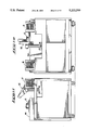
- FIG. 1 is a central cross-sectional view through the apparatus
- FIG. 2 is a top plan view of the wafer support
- FIG. 3 is a side elevational view
- FIG. 4 is a bottom plan view
- FIG. 5 is an enlarged sectional view taken along line 5--5 in FIG. 1;
- FIG. 6 is an enlarged sectional view taken along line 6--6 in FIG. 1;
- FIG. 7 is a side elevational view of the indexing and motion monitoring assemblies as seen along line 7--7 in FIG. 1;
- FIG. 8 is an enlarged fragmentary sectional view taken along line 8--8 in FIG. 4;
- FIG. 9 is a top view of a four station processing machine
- FIG. 10 is a front view
- FIG. 11 is an end view
- FIG. 12 is a side elevation view of the processing station components in a closed position
- FIG. 13 is an enlarged partial sectional view of the processing head support
- FIG. 14 is similar to FIG. 12, showing the processing station in an open condition
- FIG. 15 is a fragmentary side elevation view of the processing station showing the open processing head pivoted to a vertical position
- FIG. 16 is a view similar to FIG. 12, showing addition of a rotary actuator for the processing head.
- a single wafer processing apparatus constructed according to this invention might include a processing head that is constructed as a fully portable unit (FIGS. 1-8) for engagement by a conventional robotic arm or as a movable module (FIGS. 9-16) mounted on a machine base.
- a processing head that is constructed as a fully portable unit (FIGS. 1-8) for engagement by a conventional robotic arm or as a movable module (FIGS. 9-16) mounted on a machine base.
- the processing head When used as an attachment to a robotic arm, the processing head can be moved to or from a wafer receiving and discharging station. There wafers can be automatically or manually placed or removed between movable fingers carried by the processing head.
- the processing head can also be moved to one or more receiving bases mounted in horizontal or upright orientation in a processing cabinet housing chemical cells and supplies of liquids and gases required during a specified process for the wafer.
- the processing head When movably mounted on a machine frame, the processing head can be robotically loaded or unloaded in a first open position relative to the frame and can be shifted to a processing position or positions relative to one or more complementary processing bases on the frame.
- the processing head shown designated generally at 12 in the drawings, is designed for handling a single semiconductor wafer 10 (FIG. 1) having at least one surface to be subjected to contact with a processing fluid.
- the processing head 12 can transport an engaged wafer 10 to and from a processing base 70, either as a free-standing portable module or as a captive movable unit on a common machine frame. In both instances, the processing head has the capability of selectively rotating an engaged wafer 10 while the wafer is suspended below it within a processing fluid or while one or both wafer surfaces are subjected to a fluid spray or stream.
- the processing head 12 is centered about a first reference axis, shown in FIG. 1 as axis X--X. Mounting means is provided on the processing head for attaching it to a movable support.
- the processing head 12 detailed in FIGS. 1-8 has a mount 14 adapted to be attached to a robotic support (not shown), such as an articulated arm capable of moving the processing head 12 to a variety of positions and orientations during handling of a wafer.
- the mount 14 is of conventional design complementary to the robotic equipment with which it is to be used. Its details are unnecessary to an understanding of the present improvements.
- Processing head 12 includes a removable cover 13, a structural motor base 15 and rigid supporting spacers 16 that fix mount 14 to motor base 15. Processing head 12 also includes a radially enlarged circular shroud 18 that is outwardly open along axis X--X. The dished shroud 18 is fixed across one axial end of the processing head 12. Shroud has a peripheral rim centered about the reference axis X--X adapted to elevationally support the processing head 12 with its one axial end facing downwardly;
- a solid wafer plate 30 is coaxially centered about the axis X--X at the one axial end of the processing head 12.
- Wafer plate 30 is a rigid circular disk having opposed inner and outer surfaces 31, 32 and an inwardly projecting peripheral flange 33.
- the outer peripheral corner formed about the circular wafer plate 30 is relatively sharp and well-defined to facilitate the radial exit of fluid along its outer surface 32.
- Flange 33 overlaps a complementary cylindrical flange 20 about the interior of shroud 18, and closely abuts a peripheral horizontal flange 19 about the rim of shroud 18.
- the flanges 19, 20 and 33 form a baffle to prevent entry of liquid into the open chamber between the nonrotatable shroud 18 and the rotatable wafer plate 30.
- the horizontal flange 19 further serves as a support for processing head 12 while resting on a processing base 70 in an inverted position, as shown in FIG. 1.
- the periphery of shroud 18 also mounts a radially projecting electrical coupler 22 adapted to be connected to an electrical receiver 23 on a complementary processing base 70. Electrical power and control circuits for the equipment within the processing head 12 are completed by this connection.
- the electrical coupler and receiver 22, 23 are of conventional design. Their details are unnecessary to an understanding of the present improvements.
- Drive means are provided in the processing head.
- the drive means is operably connected to the gripper means for selectively rotating the gripper means relative to the processing head 12 and shroud 18 about the reference axis X--X.
- the wafer plate 30 is selectively rotated by a motor 34 located within cover 13.
- Motor 34 rotatably powers a driven shaft 35 having an enlargement 36 fastened to the inner surface 31 of wafer plate 30.
- the driven shaft 35 in turn is powered by a surrounding tubular motor drive shaft 38.
- Driven shaft 35 and drive shaft 38 are coaxially centered about the reference axis X--X of processing head 12.
- the drive shaft 38 and driven shaft 35 are axially splined to one another. They are held in an assembled condition by an enlarged nut 39 that threadably engages driven shaft 35 and radially overlaps the inner end of drive shaft 38.
- the above-described shaft assembly permits easy substitution of wafer plates 30 as required to support wafers 10 of different configurations or sizes. Substitution or repair of a wafer plate 30 can be readily accomplished by removal of nut 39 at the outer end of the portable processing head. One can then move the driven shaft 35 and wafer plate 30 axially from the remainder of the processing head 12. No interior access is required in the vicinity of wafer plate 30 to accomplish its assembly or disassembly.
- Gripper means is provided on the processing head 12 for holding a wafer 10 in a coaxial position perpendicular to the reference axis X--X, the gripper means being axially and radially overlapped by shroud 18.
- the gripper means includes a plurality of movable gripping fingers 40 which selectively hold a wafer 10 at a location adjacent to the outer surface 32 of wafer plate 30.
- the fingers 40 protrude axially to both sides of the wafer plate 30.
- Each is notched at 41 adjacent to its outer end to receive and engage the edges of a wafer 10.
- Fingers 40 are geometrically arranged about the reference axis of processing head 12 to receive and grip a wafer 10 within notches 41 in a coaxial position perpendicular to the axis X--X. Three fingers 40 are shown in the illustrated apparatus, but four or more fingers can be used when desired.
- each finger 40 is individually mounted in the wafer plate 30 within a flexible supporting diaphragm 42.
- the periphery of each diaphragm 42 presents a seal 43 engageable within the periphery of a complementary aperture formed through the wafer plate 30.
- the inner periphery of the seal is releasably held in place by a snap ring 44.
- Each diaphragm 42 is molded or otherwise formed integrally with one finger 40. This integral connection and support for the individual fingers 40 eliminates seams or openings across the wafer plate 30, while permitting the limited movement of finger 40 required to engage or disengage a wafer 10. Only the operative wafer-engaging section of each finger 40 is exposed to the processing fluids and gases outwardly of the wafer plate 30.
- Finger control means are located inwardly of the wafer plate 30 in the processing head 12 for moving fingers 40 in unison between closed positions engaging a wafer between them and open positions to permit receipt or discharge of a wafer.
- the finger control means comprises a combination of individual lever assemblies mounted about the inner surface 31 of wafer plate 30 and a common actuator assembly mounted within the motor base 15.
- the common actuator assembly is operably engageable with the individual lever assemblies for selectively moving the fingers in unison from their closed positions to their open positions.
- the actuator assembly does not physically engage the individual lever assemblies during normal operation and rotation of the wafer plate 30 in conjunction with the processing of a wafer 10.
- An annular push ring 50 overlies the inner ends of the linkage bars 45 adjacent to the motor base 15.
- Motor base 15 has two cylinders formed diametrically apart through reference axis X--X. Each mounts an axially movable pneumatic piston 51 having a protruding piston shaft 52 fixed to the push ring 50.
- Pistons 51 are inwardly biased by surrounding compression springs 53. Piston springs 53 normally maintain push ring 50 clear of engagement with the underlying linkage bars 45.
- the piston shaft 52 and push ring 50 extend axially to depress the pivot arms 46 about pivot shaft 47 and thereby pull the inner ends of fingers 40 radially inward to permit a wafer 10 to be positioned for subsequent gripping by the fingers 40.
- the gripping movement is effected by the yieldable spring forces on pivot arms 46 when the pressure of push ring 50 is released by terminating application of pneumatic pressure to the piston 51.
- Indexing means for this purpose is provided within processing head 12. It selectively positions the fingers 40 in preselected angular locations about the reference axis when the wafer plate 30 is not being rotated by motor 34.
- Indexing is accomplished by a multi-sided rotor plate 59 having a plurality of sides equal in number to the fingers 40 on a particular wafer plate 30 with which it is used.
- Each side of rotor plate 59 has a curved edge configuration (shown in FIG. 5) that serves as a detent in combination with an inwardly-biased roller 60.
- the motor 34 is inoperative and drive shaft 38 is freely rotatably, the inward biasing force of roller 60 will cause rotor plate 59 to pivot an angular amount necessary to center roller 60 across the engaged side of rotor plate 59 in the centered position shown in FIG. 5.
- Roller 60 is mounted at one end of a crank arm 62 pivotally supported on a supporting shaft 63 depending from the mount 14.
- crank arm 62 includes a clevis 64 pivotally joined to the outer ends of two parallel piston rods 65 that are part of two parallel pneumatic cylinder assemblies 66.
- the remaining ends of the cylinder assemblies 66 are pivotally mounted about a parallel axis on a spacer 67 that joins the motor base 15 and mount 14.
- the cylinder assemblies 66 are normally spring biased to a retracted position where roller 60 is radially clear of the rotor plate 59, which rotates in unison with the drive shaft 38. However, when rotation of drive shaft 38 terminates and indexing of the wafer plate 30 is required, the cylinder assemblies 66 are extended. This forces roller 60 radially inward against the edge of rotor plate 59 and properly centers the rotor plate as shown. The detent assures that the fingers 40 are angularly indexed when stationary to thereby meet operational requirements of associated robotic wafer handling equipment.
- a motion monitoring assembly is also provided within processing head 12 for measuring the speed and direction of rotation of the wafer plate 30 about the reference axis X--X.
- This is illustrated by an optical disk 54 fixed to the drive shaft 38 and provided with a plurality of small notches 55 and interspersed large notches 56.
- One or more optical sensor 57 overlie disk 54 to read the two sets of notches.
- the positions of the large notches 56 are utilized to confirm the angular position of the rotor plate 59 and held by the detent roller 60 in a stationary position.
- Additional sensors can be utilized to measure speed and direction of the disk by monitoring movement of the small notches 55. The details of such optical monitoring are well known and not necessary to an understanding of the present improvements.
- the general details of the processing base 70 are shown in the cross-sectional presentation of FIG. 1. It basically comprises an upwardly open bowl formed by a combination of a stationary circumferential upright wall surface 71 and an axially movable bottom wall 72.
- the bottom wall 72 is adapted to be shifted axially to sealingly engage the bottom edge of the upright wall 71. When lowered, the bottom wall 72 allows any liquid within the bowl to drain about its full periphery.
- the upright wall surface 73 and outer surface of bottom wall 72 together form an upwardly-open bowl interior centered about a second reference axis.
- This second reference axis of the processing base 70 is also identified in FIG. 1 by axis X--X, since the first and second reference axes of the portable processing head and supporting processing base 70 are coaxial when used in conjunction with one another.
- the inner diameter of the cylindrical surface 73 within the bowl relative to the axis X--X is greater than the outside diameters of the fingers 40 relative to the axis. This provides clearance within the upwardly open bowl for reception of the gripping fingers 40 which position a wafer 10 within the bowl interior.
- Mounting means is located about the bowl for selectively holding a processing head with the first and second reference axes in a fixed coaxial relationship illustrated by axis X--X in FIG. 1 and with the fingers 40 gripping a wafer within the bowl interior.
- the mounting means comprises an upwardly-facing peripheral flange 75 extending radially outward about the upright wall 71.
- the flange 75 is complementary to the flange 19 formed about shroud 18, which freely rests upon it to properly locate the processing head 12 on the processing base 70.
- Trough 78 serves to collect liquid that escapes radially outward over the upright wall surface 73 during rotation of the wafer plate 30 and associated wafer 10. It also acts as an overflow for the upwardly open bowl or basin when immersion processing techniques are being carried out within it.
- the components of the processing base 70 are located within a base enclosure formed by a surrounding cylindrical wall 79 and lower horizontal wall 82.
- the walls 72, 82 can be apertured as required for access of hoses, drains, pipes and other supply fittings to the interior of the enclosure.
- the base enclosure mounts the processing base 70 within a surrounding frame support 88.
- the bottom wall 72 of the processing bowl is supported by an annular bellows 80 extending about its full periphery to lower wall 82.
- Bellows 80 is interposed between the lower wall 82 and the lower wall 72 of the bowl for movably supporting bottom wall 72 during axial movement relative to the upright wall 71.
- Linear actuators are provided in the processing base 70 to move the bottom wall 72 parallel to axis X--X between the closed position shown in FIG. 1 and a lowered open position. These linear actuators are illustrated by one pneumatic cylinder assembly 84 in FIG. 1. In actual practice, a plurality of such cylinder assemblies 84 will be provided to move the relatively large bottom wall 72 in the required axial path.
- a drain 85 is provided in lower wall 82 at the exterior of bellows 80 for carrying away liquid received from within the bowl and from within the previously-described trough 78.
- any suitable number of liquid or gaseous jets or nozzles can be directed into the interior of the bowl.
- One illustrative jet 86 is shown extending through the movable bottom wall 72, although a plurality of similar jets or nozzles can be provided in any desired geometric pattern to direct fluid or gas against the facing surface of a wafer 10 in the required pattern.
- nozzles extending through the bottom wall 72 can be used to fill the bowl during processing and to circulate processing fluid as required.
- Peripheral liquid or gas supply nozzles and jets can also be provided about the cylindrical surface 73, as illustrated by the single jet 87 shown at the left side of FIG. 1.
- the processing base 70 lends itself to a wide variety of semiconductor wafer processing techniques requiring spraying of liquids and/or gases, as well as immersion within liquids.
- the illustrated bowl assembly permits rapid dumping of liquids from within the bowl interior. This is accomplished by moving the bottom wall 72 downwardly, which allows liquid to escape about its full periphery.
- FIGS. 9-11 generally illustrate one self-contained machine application for the processing station previously described.
- the processing head 12 and processing base 70 are essentially identical to that detailed in FIG. 1.
- the processing base 70 is stationary and supported by the frame support 88, shown as a horizontal upper cabinet surface interrupted by one or more apertures 90.
- the open periphery of each aperture 90 is complementary in shape to the exterior of the base enclosure and the adjacent linear actuating mechanism for the processing head 12, which is described below.
- FIGS. 12-16 The interconnection between each processing head 12 and its associated processing base 70 are illustrated in FIGS. 12-16.
- FIGS. 9-11 is a processing machine for semiconductor wafers. It includes four processing stations. In the drawings, three of the processing stations are shown with the processing base 70 and processing head 12 in closed positions on the upper surface of a machine cabinet. These components are not shown at the fourth processing station in order to illustrate the general shape of the receiving aperture 90.
- the machine cabinet also supports a pair of conventional portable wafer carriers 91 of a type conventionally used for supporting a stack of parallel semiconductor wafers during handling and transport. Incoming wafers would be handled by one carrier and processed wafers by the other.
- a universally movable and programmable robotic transfer arm assembly 92 is located centrally on the machine frame 88 for transferring individual wafers between carriers 91 and the four processing stations.
- the processing stations on a given cabinet might all be used for a common processing method involving application of one or more fluids to the surface(s) of a wafer positioned within them by the processing heads 12, or might be used in a sequence of processing steps wherein wafers are transferred from one processing head 12 to the next by operation of the robotic transfer arm 92.
- the processing head 12 is cantilevered by a radial arm 93.
- the arm 93 is horizontal and upwardly adjacent to the previously-described shroud 18.
- the outer end of arm 93 is pinned to a support bracket 95 that serves as the previously-described mounting means provided on the processing head for attaching it to a movable support.
- the bracket 95 is fixed to the upper end of a vertically movable support shaft 100.
- tube 94 The upper and lower ends of tube 94 are slidably sealed about the exterior of support shaft 100.
- An intermediate piston 96 is fixed to the exterior of support shaft 100 within tube 94 and sealingly engages the inside walls of tube 94.
- the support shaft 100 can be urged upwardly by introduction of pressurized air through the lower end of tube 94. It can be urged downwardly by introduction of pressurized air through the upper end of tube 94.
- processing head 12 can be pivoted about a vertically movable horizontal axis to the position shown in FIG. 15. This is accomplished manually by first removing an inner pin 101 interconnecting the outer end of radial support arm 93 and the support bracket 95. Removal of pin 101 frees the processing head 12 for pivotal movement about the horizontal center axis of the remaining pin 102.
- the processing head 12 might be raised to the position shown in FIG. 15 to permit substitution or repair of the wafer plate 30 and associated equipment, as described above.
- the electrical connections required between the reciprocable processing head 12 and the interior of the machine frame 88 can be made by flexible cables extending through the hollow support shaft 100 to a detachable electrical coupling 104 housed within a removable cover 103 that forms part of the radial support arm 93.
- the processing heads 12 illustrated in FIGS. 9-15 are capable of limited vertical movement relative to the machine frame 88. They pop up and down in response to pneumatic pressure applied to their respective supporting pneumatic cylinder assemblies. When in their raised positions, the exposed fingers 40 can be spread apart to facilitate transfer of a wafer by operation of the robotic transfer arm 92. When lowered, the fingers 40 engage and locate a wafer 10 within the upwardly open processing bowl for exposure to processing fluids.
- Rotary actuator 106 can be a hydraulic motor or electric motor designed to turn processing head 12 about the axis of shaft 100 any desired angular distance.
- the rotary actuator 106 can be selectively operated to pivot the lower end of shaft 100 about its central vertical axis through interconnecting splines 105.
- the splines 105 can also accommodate vertical movement of shaft 100 and processing head 12 in response to actuation of the pneumatic cylinder assembly described above and illustrated in FIG. 13.
- FIGS. 9-16 maintains each wafer 10 elevationally beneath the processing head 12, where it the wafer is protected from contamination by contact of falling particulates.
- the complementary processing heads 12 and processing bases 70 form enclosures that minimize contamination within the space where processing of each wafer takes place. When desired, this space can be pressurized by introduction of compressed neutral gases to assure that contaminants cannot enter the enclosure formed by the processing head 12 and base 70.
- the above-described processing stations are extremely versatile. They adapt to installations where it is desired that wafers are moved to and from a head movably supported on a processing cabinet or frame, as well as to installations where the head is required to be moved between multiple wafer handling and processing stations. In each type of installation, the wafers are securely and accurately gripped by the supporting fingers 40, and the adjacent shroud 18 is available to cover the wafer and minimize contamination of its surfaces during movement of the processing head 12.
Abstract
Description
Claims (14)
Priority Applications (3)
| Application Number | Priority Date | Filing Date | Title |
|---|---|---|---|
| US07/640,204 US5222310A (en) | 1990-05-18 | 1991-01-11 | Single wafer processor with a frame |
| US08/027,863 US5445172A (en) | 1990-05-18 | 1993-03-08 | Wafer holder with flexibly mounted gripping fingers |
| US08/489,142 US5573023A (en) | 1990-05-18 | 1995-06-08 | Single wafer processor apparatus |
Applications Claiming Priority (2)
| Application Number | Priority Date | Filing Date | Title |
|---|---|---|---|
| US07/526,243 US5168887A (en) | 1990-05-18 | 1990-05-18 | Single wafer processor apparatus |
| US07/640,204 US5222310A (en) | 1990-05-18 | 1991-01-11 | Single wafer processor with a frame |
Related Parent Applications (2)
| Application Number | Title | Priority Date | Filing Date |
|---|---|---|---|
| US07/526,243 Continuation US5168887A (en) | 1988-05-25 | 1990-05-18 | Single wafer processor apparatus |
| US07/526,243 Division US5168887A (en) | 1988-05-25 | 1990-05-18 | Single wafer processor apparatus |
Related Child Applications (1)
| Application Number | Title | Priority Date | Filing Date |
|---|---|---|---|
| US08/027,863 Continuation US5445172A (en) | 1990-05-18 | 1993-03-08 | Wafer holder with flexibly mounted gripping fingers |
Publications (1)
| Publication Number | Publication Date |
|---|---|
| US5222310A true US5222310A (en) | 1993-06-29 |
Family
ID=27062060
Family Applications (3)
| Application Number | Title | Priority Date | Filing Date |
|---|---|---|---|
| US07/640,204 Expired - Lifetime US5222310A (en) | 1990-05-18 | 1991-01-11 | Single wafer processor with a frame |
| US08/027,863 Expired - Lifetime US5445172A (en) | 1990-05-18 | 1993-03-08 | Wafer holder with flexibly mounted gripping fingers |
| US08/489,142 Expired - Lifetime US5573023A (en) | 1990-05-18 | 1995-06-08 | Single wafer processor apparatus |
Family Applications After (2)
| Application Number | Title | Priority Date | Filing Date |
|---|---|---|---|
| US08/027,863 Expired - Lifetime US5445172A (en) | 1990-05-18 | 1993-03-08 | Wafer holder with flexibly mounted gripping fingers |
| US08/489,142 Expired - Lifetime US5573023A (en) | 1990-05-18 | 1995-06-08 | Single wafer processor apparatus |
Country Status (1)
| Country | Link |
|---|---|
| US (3) | US5222310A (en) |
Cited By (126)
| Publication number | Priority date | Publication date | Assignee | Title |
|---|---|---|---|---|
| WO1995023427A3 (en) * | 1994-02-17 | 1995-12-28 | Varian Associates | Apparatus for thermal treatment of thin film wafer |
| US5573023A (en) * | 1990-05-18 | 1996-11-12 | Semitool, Inc. | Single wafer processor apparatus |
| US5791895A (en) * | 1994-02-17 | 1998-08-11 | Novellus Systems, Inc. | Apparatus for thermal treatment of thin film wafer |
| US6027631A (en) * | 1997-11-13 | 2000-02-22 | Novellus Systems, Inc. | Electroplating system with shields for varying thickness profile of deposited layer |
| US6055742A (en) * | 1997-12-30 | 2000-05-02 | Lg Semicon Co., Ltd. | Reticle cleaning apparatus for wafer exposure system |
| US6103096A (en) * | 1997-11-12 | 2000-08-15 | International Business Machines Corporation | Apparatus and method for the electrochemical etching of a wafer |
| US6106687A (en) * | 1998-04-28 | 2000-08-22 | International Business Machines Corporation | Process and diffusion baffle to modulate the cross sectional distribution of flow rate and deposition rate |
| US6113771A (en) * | 1998-04-21 | 2000-09-05 | Applied Materials, Inc. | Electro deposition chemistry |
| US6113759A (en) * | 1998-12-18 | 2000-09-05 | International Business Machines Corporation | Anode design for semiconductor deposition having novel electrical contact assembly |
| US6126798A (en) * | 1997-11-13 | 2000-10-03 | Novellus Systems, Inc. | Electroplating anode including membrane partition system and method of preventing passivation of same |
| US6136163A (en) * | 1999-03-05 | 2000-10-24 | Applied Materials, Inc. | Apparatus for electro-chemical deposition with thermal anneal chamber |
| US6139712A (en) * | 1997-11-13 | 2000-10-31 | Novellus Systems, Inc. | Method of depositing metal layer |
| US6159354A (en) * | 1997-11-13 | 2000-12-12 | Novellus Systems, Inc. | Electric potential shaping method for electroplating |
| US6164297A (en) * | 1997-06-13 | 2000-12-26 | Tokyo Electron Limited | Cleaning and drying apparatus for objects to be processed |
| WO2001004387A1 (en) * | 1999-07-12 | 2001-01-18 | Semitool, Inc. | Lift and rotate assembly for use in a workpiece processing station and a method of attaching the same |
| US6179983B1 (en) | 1997-11-13 | 2001-01-30 | Novellus Systems, Inc. | Method and apparatus for treating surface including virtual anode |
| US6228233B1 (en) | 1998-11-30 | 2001-05-08 | Applied Materials, Inc. | Inflatable compliant bladder assembly |
| US6248222B1 (en) | 1998-09-08 | 2001-06-19 | Acm Research, Inc. | Methods and apparatus for holding and positioning semiconductor workpieces during electropolishing and/or electroplating of the workpieces |
| US6251236B1 (en) | 1998-11-30 | 2001-06-26 | Applied Materials, Inc. | Cathode contact ring for electrochemical deposition |
| US6251251B1 (en) | 1998-11-16 | 2001-06-26 | International Business Machines Corporation | Anode design for semiconductor deposition |
| US6254760B1 (en) | 1999-03-05 | 2001-07-03 | Applied Materials, Inc. | Electro-chemical deposition system and method |
| US6258220B1 (en) | 1998-11-30 | 2001-07-10 | Applied Materials, Inc. | Electro-chemical deposition system |
| US6261426B1 (en) | 1999-01-22 | 2001-07-17 | International Business Machines Corporation | Method and apparatus for enhancing the uniformity of electrodeposition or electroetching |
| US6261433B1 (en) | 1998-04-21 | 2001-07-17 | Applied Materials, Inc. | Electro-chemical deposition system and method of electroplating on substrates |
| US6264752B1 (en) | 1998-03-13 | 2001-07-24 | Gary L. Curtis | Reactor for processing a microelectronic workpiece |
| US6267853B1 (en) | 1999-07-09 | 2001-07-31 | Applied Materials, Inc. | Electro-chemical deposition system |
| US6290865B1 (en) | 1998-11-30 | 2001-09-18 | Applied Materials, Inc. | Spin-rinse-drying process for electroplated semiconductor wafers |
| US6318385B1 (en) | 1998-03-13 | 2001-11-20 | Semitool, Inc. | Micro-environment chamber and system for rinsing and drying a semiconductor workpiece |
| US20010050060A1 (en) * | 1998-03-13 | 2001-12-13 | Semitool, Inc. | System for processing a workpiece |
| US20020008036A1 (en) * | 1998-02-12 | 2002-01-24 | Hui Wang | Plating apparatus and method |
| DE19859469C2 (en) * | 1998-12-22 | 2002-02-14 | Steag Micro Tech Gmbh | Device and method for treating substrates |
| US20020037641A1 (en) * | 1998-06-01 | 2002-03-28 | Ritzdorf Thomas L. | Method and apparatus for low temperature annealing of metallization micro-structure in the production of a microelectronic device |
| US20020038629A1 (en) * | 1990-05-18 | 2002-04-04 | Reardon Timothy J. | Semiconductor processing spray coating apparatus |
| US6379522B1 (en) | 1999-01-11 | 2002-04-30 | Applied Materials, Inc. | Electrodeposition chemistry for filling of apertures with reflective metal |
| US20020053509A1 (en) * | 1996-07-15 | 2002-05-09 | Hanson Kyle M. | Processing tools, components of processing tools, and method of making and using same for electrochemical processing of microelectronic workpieces |
| US20020074233A1 (en) * | 1998-02-04 | 2002-06-20 | Semitool, Inc. | Method and apparatus for low temperature annealing of metallization micro-structures in the production of a microelectronic device |
| US6413436B1 (en) | 1999-01-27 | 2002-07-02 | Semitool, Inc. | Selective treatment of the surface of a microelectronic workpiece |
| US6416647B1 (en) | 1998-04-21 | 2002-07-09 | Applied Materials, Inc. | Electro-chemical deposition cell for face-up processing of single semiconductor substrates |
| US6423636B1 (en) * | 1999-11-19 | 2002-07-23 | Applied Materials, Inc. | Process sequence for improved seed layer productivity and achieving 3mm edge exclusion for a copper metalization process on semiconductor wafer |
| US6423642B1 (en) | 1998-03-13 | 2002-07-23 | Semitool, Inc. | Reactor for processing a semiconductor wafer |
| US20020112964A1 (en) * | 2000-07-12 | 2002-08-22 | Applied Materials, Inc. | Process window for gap-fill on very high aspect ratio structures using additives in low acid copper baths |
| US20020113039A1 (en) * | 1999-07-09 | 2002-08-22 | Mok Yeuk-Fai Edwin | Integrated semiconductor substrate bevel cleaning apparatus and method |
| US20020125141A1 (en) * | 1999-04-13 | 2002-09-12 | Wilson Gregory J. | Tuning electrodes used in a reactor for electrochemically processing a microelectronic workpiece |
| US6478937B2 (en) | 2001-01-19 | 2002-11-12 | Applied Material, Inc. | Substrate holder system with substrate extension apparatus and associated method |
| US6492284B2 (en) | 1999-01-22 | 2002-12-10 | Semitool, Inc. | Reactor for processing a workpiece using sonic energy |
| US6511914B2 (en) | 1999-01-22 | 2003-01-28 | Semitool, Inc. | Reactor for processing a workpiece using sonic energy |
| WO2003008140A2 (en) * | 2001-07-16 | 2003-01-30 | Semitool, Inc. | Apparatus for processing a workpiece |
| US6516815B1 (en) | 1999-07-09 | 2003-02-11 | Applied Materials, Inc. | Edge bead removal/spin rinse dry (EBR/SRD) module |
| US6543156B2 (en) | 2000-01-12 | 2003-04-08 | Semitool, Inc. | Method and apparatus for high-pressure wafer processing and drying |
| US6544399B1 (en) | 1999-01-11 | 2003-04-08 | Applied Materials, Inc. | Electrodeposition chemistry for filling apertures with reflective metal |
| US6548411B2 (en) | 1999-01-22 | 2003-04-15 | Semitool, Inc. | Apparatus and methods for processing a workpiece |
| US6551484B2 (en) | 1999-04-08 | 2003-04-22 | Applied Materials, Inc. | Reverse voltage bias for electro-chemical plating system and method |
| US6551488B1 (en) | 1999-04-08 | 2003-04-22 | Applied Materials, Inc. | Segmenting of processing system into wet and dry areas |
| US6557237B1 (en) | 1999-04-08 | 2003-05-06 | Applied Materials, Inc. | Removable modular cell for electro-chemical plating and method |
| US6558518B1 (en) | 1999-07-08 | 2003-05-06 | Ebara Corporation | Method and apparatus for plating substrate and plating facility |
| US6571657B1 (en) | 1999-04-08 | 2003-06-03 | Applied Materials Inc. | Multiple blade robot adjustment apparatus and associated method |
| US6576110B2 (en) | 2000-07-07 | 2003-06-10 | Applied Materials, Inc. | Coated anode apparatus and associated method |
| US6582578B1 (en) | 1999-04-08 | 2003-06-24 | Applied Materials, Inc. | Method and associated apparatus for tilting a substrate upon entry for metal deposition |
| US6585876B2 (en) | 1999-04-08 | 2003-07-01 | Applied Materials Inc. | Flow diffuser to be used in electro-chemical plating system and method |
| US20030146102A1 (en) * | 2002-02-05 | 2003-08-07 | Applied Materials, Inc. | Method for forming copper interconnects |
| US6610189B2 (en) | 2001-01-03 | 2003-08-26 | Applied Materials, Inc. | Method and associated apparatus to mechanically enhance the deposition of a metal film within a feature |
| US20030159277A1 (en) * | 2002-02-22 | 2003-08-28 | Randy Harris | Method and apparatus for manually and automatically processing microelectronic workpieces |
| US20030159921A1 (en) * | 2002-02-22 | 2003-08-28 | Randy Harris | Apparatus with processing stations for manually and automatically processing microelectronic workpieces |
| US6613214B2 (en) | 1998-11-30 | 2003-09-02 | Applied Materials, Inc. | Electric contact element for electrochemical deposition system and method |
| US20030170949A1 (en) * | 2002-03-08 | 2003-09-11 | Tokyo Electron Limited | Substrate processing apparatus and substrate processing method |
| US6623609B2 (en) | 1999-07-12 | 2003-09-23 | Semitool, Inc. | Lift and rotate assembly for use in a workpiece processing station and a method of attaching the same |
| US6632292B1 (en) | 1998-03-13 | 2003-10-14 | Semitool, Inc. | Selective treatment of microelectronic workpiece surfaces |
| US20030201166A1 (en) * | 2002-04-29 | 2003-10-30 | Applied Materials, Inc. | method for regulating the electrical power applied to a substrate during an immersion process |
| US20030209443A1 (en) * | 2002-05-09 | 2003-11-13 | Applied Materials, Inc. | Substrate support with fluid retention band |
| US20030221953A1 (en) * | 2000-01-03 | 2003-12-04 | Oberlitner Thomas H. | Microelectronic workpiece processing tool including a processing reactor having a paddle assembly for agitation of a processing fluid proximate to the workpiece |
| US6662673B1 (en) | 1999-04-08 | 2003-12-16 | Applied Materials, Inc. | Linear motion apparatus and associated method |
| US20040003873A1 (en) * | 1999-03-05 | 2004-01-08 | Applied Materials, Inc. | Method and apparatus for annealing copper films |
| US6680253B2 (en) | 1999-01-22 | 2004-01-20 | Semitool, Inc. | Apparatus for processing a workpiece |
| US20040020780A1 (en) * | 2001-01-18 | 2004-02-05 | Hey H. Peter W. | Immersion bias for use in electro-chemical plating system |
| US20040049911A1 (en) * | 2002-07-16 | 2004-03-18 | Harris Randy A. | Apparatuses and method for transferring and/or pre-processing microelectronic workpieces |
| US20040079633A1 (en) * | 2000-07-05 | 2004-04-29 | Applied Materials, Inc. | Apparatus for electro chemical deposition of copper metallization with the capability of in-situ thermal annealing |
| US6736945B2 (en) * | 2000-02-28 | 2004-05-18 | Electroplating Engineers Of Japan Limited | Wafer plating apparatus |
| US6749391B2 (en) | 1996-07-15 | 2004-06-15 | Semitool, Inc. | Microelectronic workpiece transfer devices and methods of using such devices in the processing of microelectronic workpieces |
| US6749390B2 (en) | 1997-12-15 | 2004-06-15 | Semitool, Inc. | Integrated tools with transfer devices for handling microelectronic workpieces |
| US6752584B2 (en) | 1996-07-15 | 2004-06-22 | Semitool, Inc. | Transfer devices for handling microelectronic workpieces within an environment of a processing machine and methods of manufacturing and using such devices in the processing of microelectronic workpieces |
| US20040118694A1 (en) * | 2002-12-19 | 2004-06-24 | Applied Materials, Inc. | Multi-chemistry electrochemical processing system |
| US6754975B2 (en) * | 2001-01-16 | 2004-06-29 | Taiwan Semiconductor Manufacturing Co., Ltd | Microelectronic substrate retainer apparatus providing reduced microelectronic substrate damage |
| US20040140203A1 (en) * | 2003-01-21 | 2004-07-22 | Applied Materials,Inc. | Liquid isolation of contact rings |
| US6770565B2 (en) | 2002-01-08 | 2004-08-03 | Applied Materials Inc. | System for planarizing metal conductive layers |
| US20040149573A1 (en) * | 2003-01-31 | 2004-08-05 | Applied Materials, Inc. | Contact ring with embedded flexible contacts |
| US20040154185A1 (en) * | 1997-07-10 | 2004-08-12 | Applied Materials, Inc. | Method and apparatus for heating and cooling substrates |
| US20040173454A1 (en) * | 2001-10-16 | 2004-09-09 | Applied Materials, Inc. | Apparatus and method for electro chemical plating using backsid electrical contacte |
| US20040178065A1 (en) * | 2001-03-16 | 2004-09-16 | Semitool, Inc. | Electrode semiconductor workpiece holder and processing methods |
| US6796517B1 (en) | 2000-03-09 | 2004-09-28 | Advanced Micro Devices, Inc. | Apparatus for the application of developing solution to a semiconductor wafer |
| US20040200725A1 (en) * | 2003-04-09 | 2004-10-14 | Applied Materials Inc. | Application of antifoaming agent to reduce defects in a semiconductor electrochemical plating process |
| US6806186B2 (en) | 1998-02-04 | 2004-10-19 | Semitool, Inc. | Submicron metallization using electrochemical deposition |
| US20040206628A1 (en) * | 2003-04-18 | 2004-10-21 | Applied Materials, Inc. | Electrical bias during wafer exit from electrolyte bath |
| US20040209414A1 (en) * | 2003-04-18 | 2004-10-21 | Applied Materials, Inc. | Two position anneal chamber |
| US6808612B2 (en) | 2000-05-23 | 2004-10-26 | Applied Materials, Inc. | Method and apparatus to overcome anomalies in copper seed layers and to tune for feature size and aspect ratio |
| US6824612B2 (en) | 2001-12-26 | 2004-11-30 | Applied Materials, Inc. | Electroless plating system |
| US20040241998A1 (en) * | 1999-01-22 | 2004-12-02 | Hanson Kyle M. | System for processing a workpiece |
| US20040245094A1 (en) * | 2003-06-06 | 2004-12-09 | Mchugh Paul R. | Integrated microfeature workpiece processing tools with registration systems for paddle reactors |
| US6837978B1 (en) | 1999-04-08 | 2005-01-04 | Applied Materials, Inc. | Deposition uniformity control for electroplating apparatus, and associated method |
| US20050000817A1 (en) * | 2003-07-01 | 2005-01-06 | Mchugh Paul R. | Reactors having multiple electrodes and/or enclosed reciprocating paddles, and associated methods |
| US20050035046A1 (en) * | 2003-06-06 | 2005-02-17 | Hanson Kyle M. | Wet chemical processing chambers for processing microfeature workpieces |
| US20050050767A1 (en) * | 2003-06-06 | 2005-03-10 | Hanson Kyle M. | Wet chemical processing chambers for processing microfeature workpieces |
| US20050056538A1 (en) * | 2003-09-17 | 2005-03-17 | Applied Materials, Inc. | Insoluble anode with an auxiliary electrode |
| US20050063798A1 (en) * | 2003-06-06 | 2005-03-24 | Davis Jeffry Alan | Interchangeable workpiece handling apparatus and associated tool for processing microfeature workpieces |
| US20050077182A1 (en) * | 2003-10-10 | 2005-04-14 | Applied Materials, Inc. | Volume measurement apparatus and method |
| US20050092601A1 (en) * | 2003-10-29 | 2005-05-05 | Harald Herchen | Electrochemical plating cell having a diffusion member |
| US20050092602A1 (en) * | 2003-10-29 | 2005-05-05 | Harald Herchen | Electrochemical plating cell having a membrane stack |
| US6913680B1 (en) | 2000-05-02 | 2005-07-05 | Applied Materials, Inc. | Method of application of electrical biasing to enhance metal deposition |
| US20050199489A1 (en) * | 2002-01-28 | 2005-09-15 | Applied Materials, Inc. | Electroless deposition apparatus |
| US20050217707A1 (en) * | 1998-03-13 | 2005-10-06 | Aegerter Brian K | Selective processing of microelectronic workpiece surfaces |
| US20050218000A1 (en) * | 2004-04-06 | 2005-10-06 | Applied Materials, Inc. | Conditioning of contact leads for metal plating systems |
| US20050260345A1 (en) * | 2003-10-06 | 2005-11-24 | Applied Materials, Inc. | Apparatus for electroless deposition of metals onto semiconductor substrates |
| US20050284754A1 (en) * | 2004-06-24 | 2005-12-29 | Harald Herchen | Electric field reducing thrust plate |
| US20060033678A1 (en) * | 2004-01-26 | 2006-02-16 | Applied Materials, Inc. | Integrated electroless deposition system |
| US7025861B2 (en) | 2003-02-06 | 2006-04-11 | Applied Materials | Contact plating apparatus |
| US20060102467A1 (en) * | 2004-11-15 | 2006-05-18 | Harald Herchen | Current collimation for thin seed and direct plating |
| US20060175201A1 (en) * | 2005-02-07 | 2006-08-10 | Hooman Hafezi | Immersion process for electroplating applications |
| US7102763B2 (en) | 2000-07-08 | 2006-09-05 | Semitool, Inc. | Methods and apparatus for processing microelectronic workpieces using metrology |
| US20070014958A1 (en) * | 2005-07-08 | 2007-01-18 | Chaplin Ernest R | Hanger labels, label assemblies and methods for forming the same |
| US20070026529A1 (en) * | 2005-07-26 | 2007-02-01 | Applied Materials, Inc. | System and methods for measuring chemical concentrations of a plating solution |
| US7205153B2 (en) | 2003-04-11 | 2007-04-17 | Applied Materials, Inc. | Analytical reagent for acid copper sulfate solutions |
| US20070144912A1 (en) * | 2003-07-01 | 2007-06-28 | Woodruff Daniel J | Linearly translating agitators for processing microfeature workpieces, and associated methods |
| US20080052948A1 (en) * | 2006-08-30 | 2008-03-06 | Semes Co., Ltd | Spin head and substrate treating method using the same |
| US20080155852A1 (en) * | 2006-12-29 | 2008-07-03 | Olgado Donald J K | Multiple substrate vapor drying systems and methods |
| US20080178460A1 (en) * | 2007-01-29 | 2008-07-31 | Woodruff Daniel J | Protected magnets and magnet shielding for processing microfeature workpieces, and associated systems and methods |
| US8967935B2 (en) | 2011-07-06 | 2015-03-03 | Tel Nexx, Inc. | Substrate loader and unloader |
| US9421617B2 (en) | 2011-06-22 | 2016-08-23 | Tel Nexx, Inc. | Substrate holder |
Families Citing this family (33)
| Publication number | Priority date | Publication date | Assignee | Title |
|---|---|---|---|---|
| US5664337A (en) * | 1996-03-26 | 1997-09-09 | Semitool, Inc. | Automated semiconductor processing systems |
| US6685817B1 (en) * | 1995-05-26 | 2004-02-03 | Formfactor, Inc. | Method and apparatus for controlling plating over a face of a substrate |
| US6090261A (en) * | 1995-05-26 | 2000-07-18 | Formfactor, Inc. | Method and apparatus for controlling plating over a face of a substrate |
| US6286688B1 (en) * | 1996-04-03 | 2001-09-11 | Scp Global Technologies, Inc. | Compliant silicon wafer handling system |
| US6001234A (en) * | 1997-09-30 | 1999-12-14 | Semitool, Inc. | Methods for plating semiconductor workpieces using a workpiece-engaging electrode assembly with sealing boot |
| US6645355B2 (en) | 1996-07-15 | 2003-11-11 | Semitool, Inc. | Semiconductor processing apparatus having lift and tilt mechanism |
| US7087143B1 (en) | 1996-07-15 | 2006-08-08 | Semitool, Inc. | Plating system for semiconductor materials |
| US5980706A (en) * | 1996-07-15 | 1999-11-09 | Semitool, Inc. | Electrode semiconductor workpiece holder |
| US6599412B1 (en) * | 1997-09-30 | 2003-07-29 | Semitool, Inc. | In-situ cleaning processes for semiconductor electroplating electrodes |
| US5778554A (en) * | 1996-07-15 | 1998-07-14 | Oliver Design, Inc. | Wafer spin dryer and method of drying a wafer |
| US6805778B1 (en) | 1996-07-15 | 2004-10-19 | Semitool, Inc. | Contact assembly for supplying power to workpieces during electrochemical processing |
| US5731678A (en) * | 1996-07-15 | 1998-03-24 | Semitool, Inc. | Processing head for semiconductor processing machines |
| US6091498A (en) * | 1996-07-15 | 2000-07-18 | Semitool, Inc. | Semiconductor processing apparatus having lift and tilt mechanism |
| US6358388B1 (en) | 1996-07-15 | 2002-03-19 | Semitool, Inc. | Plating system workpiece support having workpiece-engaging electrodes with distal contact-part and dielectric cover |
| JP3831043B2 (en) * | 1997-01-24 | 2006-10-11 | 東京エレクトロン株式会社 | Rotation processing device |
| US6132587A (en) * | 1998-10-19 | 2000-10-17 | Jorne; Jacob | Uniform electroplating of wafers |
| USD422866S (en) * | 1999-01-07 | 2000-04-18 | Tooltek Engineering Corporation | Substrate fixturing device |
| US6340090B1 (en) | 1999-01-07 | 2002-01-22 | Tooltek Engineering Corporation | Substrate fixturing device |
| US6167893B1 (en) * | 1999-02-09 | 2001-01-02 | Novellus Systems, Inc. | Dynamic chuck for semiconductor wafer or other substrate |
| US6774056B2 (en) * | 1999-11-10 | 2004-08-10 | Semitool, Inc. | Sonic immersion process system and methods |
| US20050145499A1 (en) * | 2000-06-05 | 2005-07-07 | Applied Materials, Inc. | Plating of a thin metal seed layer |
| US6659116B1 (en) * | 2000-06-26 | 2003-12-09 | Lam Research Corporation | System for wafer carrier in-process clean and rinse |
| US6544391B1 (en) * | 2000-10-17 | 2003-04-08 | Semitool, Inc. | Reactor for electrochemically processing a microelectronic workpiece including improved electrode assembly |
| US6558562B2 (en) | 2000-12-01 | 2003-05-06 | Speedfam-Ipec Corporation | Work piece wand and method for processing work pieces using a work piece handling wand |
| US6875331B2 (en) * | 2002-07-11 | 2005-04-05 | Applied Materials, Inc. | Anode isolation by diffusion differentials |
| US7128823B2 (en) | 2002-07-24 | 2006-10-31 | Applied Materials, Inc. | Anolyte for copper plating |
| US20040134775A1 (en) * | 2002-07-24 | 2004-07-15 | Applied Materials, Inc. | Electrochemical processing cell |
| US7223323B2 (en) | 2002-07-24 | 2007-05-29 | Applied Materials, Inc. | Multi-chemistry plating system |
| US7247222B2 (en) * | 2002-07-24 | 2007-07-24 | Applied Materials, Inc. | Electrochemical processing cell |
| KR101087633B1 (en) * | 2002-11-15 | 2011-11-30 | 가부시키가이샤 에바라 세이사꾸쇼 | Substrate processing apparatus and substrate processing method |
| US7473339B2 (en) * | 2003-04-18 | 2009-01-06 | Applied Materials, Inc. | Slim cell platform plumbing |
| US8526709B2 (en) | 2011-01-13 | 2013-09-03 | Lam Research Corporation | Methods and apparatus for detecting multiple objects |
| US10069030B2 (en) * | 2015-12-14 | 2018-09-04 | Solarcity Corporation | Load lock solar cell transfer system |
Citations (6)
| Publication number | Priority date | Publication date | Assignee | Title |
|---|---|---|---|---|
| US4313266A (en) * | 1980-05-01 | 1982-02-02 | The Silicon Valley Group, Inc. | Method and apparatus for drying wafers |
| US4339297A (en) * | 1981-04-14 | 1982-07-13 | Seiichiro Aigo | Apparatus for etching of oxide film on semiconductor wafer |
| US4601627A (en) * | 1983-04-23 | 1986-07-22 | Dainippon Screen Manufacturing Co., Ltd. | Apparatus for transferring thin sheet-like article such as wafers |
| US4788994A (en) * | 1986-08-13 | 1988-12-06 | Dainippon Screen Mfg. Co. | Wafer holding mechanism |
| US4936940A (en) * | 1987-06-26 | 1990-06-26 | Hitachi, Ltd. | Equipment for surface treatment |
| US4938691A (en) * | 1987-11-17 | 1990-07-03 | Tel Sagami Limited | Heat-treating apparatus |
Family Cites Families (28)
| Publication number | Priority date | Publication date | Assignee | Title |
|---|---|---|---|---|
| GB1200141A (en) * | 1968-05-28 | 1970-07-29 | English Electric Co Ltd | Grabs |
| US3585668A (en) * | 1969-06-02 | 1971-06-22 | Bell Telephone Labor Inc | Brush cleaning apparatus for semiconductor slices |
| SE346129B (en) * | 1970-12-10 | 1972-06-26 | Nordnero Ab | |
| JPS5720445A (en) * | 1980-07-11 | 1982-02-02 | Citizen Watch Co Ltd | Handling device for wafer |
| SU1060470A1 (en) * | 1982-11-18 | 1983-12-15 | Лозовский Кузнечно-Механический Завод Им.60-Летия Ссср | Industrial robot gripper |
| US4616971A (en) * | 1983-10-11 | 1986-10-14 | Fairchild Camera And Instrument Corp. | Robotic hand and method for manipulating printed circuit boards |
| JPS60231330A (en) * | 1984-04-28 | 1985-11-16 | Seiichiro Sogo | Semiconductor material processing apparatus |
| JPH0673352B2 (en) * | 1984-05-18 | 1994-09-14 | 松下電器産業株式会社 | High pressure jet cleaning method |
| DE3685835T2 (en) * | 1985-04-17 | 1993-02-18 | Hitachi Ltd | GRIPPER TOOL. |
| US4687542A (en) * | 1985-10-24 | 1987-08-18 | Texas Instruments Incorporated | Vacuum processing system |
| US4651440A (en) * | 1986-05-16 | 1987-03-24 | Eastman Kodak Company | Spin drying apparatus |
| JPS62295839A (en) * | 1986-06-16 | 1987-12-23 | Shin Meiwa Ind Co Ltd | Gripping device |
| US4817556A (en) * | 1987-05-04 | 1989-04-04 | Varian Associates, Inc. | Apparatus for retaining wafers |
| US5040484A (en) * | 1987-05-04 | 1991-08-20 | Varian Associates, Inc. | Apparatus for retaining wafers |
| JPS6425538A (en) * | 1987-07-22 | 1989-01-27 | Hitachi Ltd | Wet treating apparatus |
| JPH01140730A (en) * | 1987-11-27 | 1989-06-01 | Hitachi Ltd | Transfer of sheet-like object and transfer apparatus |
| US4902608A (en) * | 1987-12-17 | 1990-02-20 | Texas Instruments Incorporated | Immersion development and rinse machine and process |
| US5224504A (en) * | 1988-05-25 | 1993-07-06 | Semitool, Inc. | Single wafer processor |
| US5168887A (en) * | 1990-05-18 | 1992-12-08 | Semitool, Inc. | Single wafer processor apparatus |
| US5168886A (en) * | 1988-05-25 | 1992-12-08 | Semitool, Inc. | Single wafer processor |
| US5230743A (en) * | 1988-05-25 | 1993-07-27 | Semitool, Inc. | Method for single wafer processing in which a semiconductor wafer is contacted with a fluid |
| JPH01301732A (en) * | 1988-05-31 | 1989-12-05 | Sumitomo Bakelite Co Ltd | Highly functional formed product and production thereof |
| JPH01304732A (en) * | 1988-06-01 | 1989-12-08 | Nec Corp | Semiconductor wafer washer |
| JPH01316934A (en) * | 1988-06-15 | 1989-12-21 | Nec Corp | Substrate wet processor |
| JPH02140730A (en) * | 1988-11-22 | 1990-05-30 | Shiojiri Kogyo Kk | Led for light source and data imprinting device for camera provided therewith |
| DE3903607A1 (en) * | 1989-02-08 | 1990-08-09 | Leybold Ag | DEVICE FOR CLEANING, CHECKING AND CLASSIFYING WORKPIECES |
| US5156174A (en) * | 1990-05-18 | 1992-10-20 | Semitool, Inc. | Single wafer processor with a bowl |
| US5222310A (en) * | 1990-05-18 | 1993-06-29 | Semitool, Inc. | Single wafer processor with a frame |
-
1991
- 1991-01-11 US US07/640,204 patent/US5222310A/en not_active Expired - Lifetime
-
1993
- 1993-03-08 US US08/027,863 patent/US5445172A/en not_active Expired - Lifetime
-
1995
- 1995-06-08 US US08/489,142 patent/US5573023A/en not_active Expired - Lifetime
Patent Citations (6)
| Publication number | Priority date | Publication date | Assignee | Title |
|---|---|---|---|---|
| US4313266A (en) * | 1980-05-01 | 1982-02-02 | The Silicon Valley Group, Inc. | Method and apparatus for drying wafers |
| US4339297A (en) * | 1981-04-14 | 1982-07-13 | Seiichiro Aigo | Apparatus for etching of oxide film on semiconductor wafer |
| US4601627A (en) * | 1983-04-23 | 1986-07-22 | Dainippon Screen Manufacturing Co., Ltd. | Apparatus for transferring thin sheet-like article such as wafers |
| US4788994A (en) * | 1986-08-13 | 1988-12-06 | Dainippon Screen Mfg. Co. | Wafer holding mechanism |
| US4936940A (en) * | 1987-06-26 | 1990-06-26 | Hitachi, Ltd. | Equipment for surface treatment |
| US4938691A (en) * | 1987-11-17 | 1990-07-03 | Tel Sagami Limited | Heat-treating apparatus |
Cited By (204)
| Publication number | Priority date | Publication date | Assignee | Title |
|---|---|---|---|---|
| US20020038629A1 (en) * | 1990-05-18 | 2002-04-04 | Reardon Timothy J. | Semiconductor processing spray coating apparatus |
| US5573023A (en) * | 1990-05-18 | 1996-11-12 | Semitool, Inc. | Single wafer processor apparatus |
| US7094291B2 (en) | 1990-05-18 | 2006-08-22 | Semitool, Inc. | Semiconductor processing apparatus |
| US20020040679A1 (en) * | 1990-05-18 | 2002-04-11 | Reardon Timothy J. | Semiconductor processing apparatus |
| US6375741B2 (en) * | 1991-03-06 | 2002-04-23 | Timothy J. Reardon | Semiconductor processing spray coating apparatus |
| US5791895A (en) * | 1994-02-17 | 1998-08-11 | Novellus Systems, Inc. | Apparatus for thermal treatment of thin film wafer |
| WO1995023427A3 (en) * | 1994-02-17 | 1995-12-28 | Varian Associates | Apparatus for thermal treatment of thin film wafer |
| US20020053509A1 (en) * | 1996-07-15 | 2002-05-09 | Hanson Kyle M. | Processing tools, components of processing tools, and method of making and using same for electrochemical processing of microelectronic workpieces |
| US20040228719A1 (en) * | 1996-07-15 | 2004-11-18 | Woodruff Daniel J. | Transfer devices for handling microelectronic workpieces within an environment of a processing machine and methods of manufacturing and using such devices in the processing of microelectronic workpieces |
| US6749391B2 (en) | 1996-07-15 | 2004-06-15 | Semitool, Inc. | Microelectronic workpiece transfer devices and methods of using such devices in the processing of microelectronic workpieces |
| US6752584B2 (en) | 1996-07-15 | 2004-06-22 | Semitool, Inc. | Transfer devices for handling microelectronic workpieces within an environment of a processing machine and methods of manufacturing and using such devices in the processing of microelectronic workpieces |
| US6921467B2 (en) | 1996-07-15 | 2005-07-26 | Semitool, Inc. | Processing tools, components of processing tools, and method of making and using same for electrochemical processing of microelectronic workpieces |
| US6164297A (en) * | 1997-06-13 | 2000-12-26 | Tokyo Electron Limited | Cleaning and drying apparatus for objects to be processed |
| US6929774B2 (en) | 1997-07-10 | 2005-08-16 | Applied Materials, Inc. | Method and apparatus for heating and cooling substrates |
| US20040154185A1 (en) * | 1997-07-10 | 2004-08-12 | Applied Materials, Inc. | Method and apparatus for heating and cooling substrates |
| US6103096A (en) * | 1997-11-12 | 2000-08-15 | International Business Machines Corporation | Apparatus and method for the electrochemical etching of a wafer |
| US6569299B1 (en) | 1997-11-13 | 2003-05-27 | Novellus Systems, Inc. | Membrane partition system for plating of wafers |
| US6436249B1 (en) | 1997-11-13 | 2002-08-20 | Novellus Systems, Inc. | Clamshell apparatus for electrochemically treating semiconductor wafers |
| US6027631A (en) * | 1997-11-13 | 2000-02-22 | Novellus Systems, Inc. | Electroplating system with shields for varying thickness profile of deposited layer |
| US6179983B1 (en) | 1997-11-13 | 2001-01-30 | Novellus Systems, Inc. | Method and apparatus for treating surface including virtual anode |
| US6159354A (en) * | 1997-11-13 | 2000-12-12 | Novellus Systems, Inc. | Electric potential shaping method for electroplating |
| US6156167A (en) * | 1997-11-13 | 2000-12-05 | Novellus Systems, Inc. | Clamshell apparatus for electrochemically treating semiconductor wafers |
| US6139712A (en) * | 1997-11-13 | 2000-10-31 | Novellus Systems, Inc. | Method of depositing metal layer |
| US6126798A (en) * | 1997-11-13 | 2000-10-03 | Novellus Systems, Inc. | Electroplating anode including membrane partition system and method of preventing passivation of same |
| US6589401B1 (en) | 1997-11-13 | 2003-07-08 | Novellus Systems, Inc. | Apparatus for electroplating copper onto semiconductor wafer |
| US6193859B1 (en) * | 1997-11-13 | 2001-02-27 | Novellus Systems, Inc. | Electric potential shaping apparatus for holding a semiconductor wafer during electroplating |
| US6343793B1 (en) | 1997-11-13 | 2002-02-05 | Novellus Systems, Inc. | Dual channel rotary union |
| US6749390B2 (en) | 1997-12-15 | 2004-06-15 | Semitool, Inc. | Integrated tools with transfer devices for handling microelectronic workpieces |
| US6055742A (en) * | 1997-12-30 | 2000-05-02 | Lg Semicon Co., Ltd. | Reticle cleaning apparatus for wafer exposure system |
| US7144805B2 (en) | 1998-02-04 | 2006-12-05 | Semitool, Inc. | Method of submicron metallization using electrochemical deposition of recesses including a first deposition at a first current density and a second deposition at an increased current density |
| US20020074233A1 (en) * | 1998-02-04 | 2002-06-20 | Semitool, Inc. | Method and apparatus for low temperature annealing of metallization micro-structures in the production of a microelectronic device |
| US7462269B2 (en) | 1998-02-04 | 2008-12-09 | Semitool, Inc. | Method for low temperature annealing of metallization micro-structures in the production of a microelectronic device |
| US6508920B1 (en) | 1998-02-04 | 2003-01-21 | Semitool, Inc. | Apparatus for low-temperature annealing of metallization microstructures in the production of a microelectronic device |
| US6806186B2 (en) | 1998-02-04 | 2004-10-19 | Semitool, Inc. | Submicron metallization using electrochemical deposition |
| US20050051436A1 (en) * | 1998-02-04 | 2005-03-10 | Semitool, Inc. | Method of submicron metallization using electrochemical deposition of recesses including a first deposition at a first current density and a second deposition at an increased current density |
| US6391166B1 (en) | 1998-02-12 | 2002-05-21 | Acm Research, Inc. | Plating apparatus and method |
| US20020008036A1 (en) * | 1998-02-12 | 2002-01-24 | Hui Wang | Plating apparatus and method |
| US6666922B2 (en) | 1998-03-13 | 2003-12-23 | Semitool, Inc. | System for processing a workpiece |
| US6494956B2 (en) | 1998-03-13 | 2002-12-17 | Semitool, Inc. | System for processing a workpiece |
| US6350319B1 (en) | 1998-03-13 | 2002-02-26 | Semitool, Inc. | Micro-environment reactor for processing a workpiece |
| US6264752B1 (en) | 1998-03-13 | 2001-07-24 | Gary L. Curtis | Reactor for processing a microelectronic workpiece |
| US6632292B1 (en) | 1998-03-13 | 2003-10-14 | Semitool, Inc. | Selective treatment of microelectronic workpiece surfaces |
| US6660098B2 (en) | 1998-03-13 | 2003-12-09 | Semitool, Inc. | System for processing a workpiece |
| US20050032391A1 (en) * | 1998-03-13 | 2005-02-10 | Semitool, Inc. | Method for processing a semiconductor wafer |
| US20010050060A1 (en) * | 1998-03-13 | 2001-12-13 | Semitool, Inc. | System for processing a workpiece |
| US20050217707A1 (en) * | 1998-03-13 | 2005-10-06 | Aegerter Brian K | Selective processing of microelectronic workpiece surfaces |
| US20050233589A1 (en) * | 1998-03-13 | 2005-10-20 | Aegerter Brian K | Processes for removing residue from a workpiece |
| US6558470B2 (en) | 1998-03-13 | 2003-05-06 | Semitool, Inc. | Reactor for processing a microelectronic workpiece |
| US7399713B2 (en) | 1998-03-13 | 2008-07-15 | Semitool, Inc. | Selective treatment of microelectric workpiece surfaces |
| US6423642B1 (en) | 1998-03-13 | 2002-07-23 | Semitool, Inc. | Reactor for processing a semiconductor wafer |
| US6318385B1 (en) | 1998-03-13 | 2001-11-20 | Semitool, Inc. | Micro-environment chamber and system for rinsing and drying a semiconductor workpiece |
| US20040023494A1 (en) * | 1998-03-13 | 2004-02-05 | Semitool, Inc. | Selective treatment of microelectronic workpiece surfaces |
| US6695914B2 (en) | 1998-03-13 | 2004-02-24 | Semitool, Inc. | System for processing a workpiece |
| US6446643B2 (en) | 1998-03-13 | 2002-09-10 | Semitool, Inc. | Micro-environment chamber and system for rinsing and drying a semiconductor workpiece |
| US6447633B1 (en) | 1998-03-13 | 2002-09-10 | Semitdol, Inc. | Reactor for processing a semiconductor wafer |
| US6997988B2 (en) | 1998-03-13 | 2006-02-14 | Semitool, Inc. | System for processing a workpiece |
| US20040020781A1 (en) * | 1998-04-21 | 2004-02-05 | Applied Materials, Inc. | Electro-chemical deposition cell for face-up processing of single semiconductor substrates |
| US6610191B2 (en) | 1998-04-21 | 2003-08-26 | Applied Materials, Inc. | Electro deposition chemistry |
| US6350366B1 (en) | 1998-04-21 | 2002-02-26 | Applied Materials, Inc. | Electro deposition chemistry |
| USRE40218E1 (en) * | 1998-04-21 | 2008-04-08 | Uziel Landau | Electro-chemical deposition system and method of electroplating on substrates |
| US20030205474A1 (en) * | 1998-04-21 | 2003-11-06 | Applied Materials, Inc. | Electro deposition chemistry |
| US6416647B1 (en) | 1998-04-21 | 2002-07-09 | Applied Materials, Inc. | Electro-chemical deposition cell for face-up processing of single semiconductor substrates |
| US6113771A (en) * | 1998-04-21 | 2000-09-05 | Applied Materials, Inc. | Electro deposition chemistry |
| US6261433B1 (en) | 1998-04-21 | 2001-07-17 | Applied Materials, Inc. | Electro-chemical deposition system and method of electroplating on substrates |
| US6106687A (en) * | 1998-04-28 | 2000-08-22 | International Business Machines Corporation | Process and diffusion baffle to modulate the cross sectional distribution of flow rate and deposition rate |
| US6994776B2 (en) * | 1998-06-01 | 2006-02-07 | Semitool Inc. | Method and apparatus for low temperature annealing of metallization micro-structure in the production of a microelectronic device |
| US20020037641A1 (en) * | 1998-06-01 | 2002-03-28 | Ritzdorf Thomas L. | Method and apparatus for low temperature annealing of metallization micro-structure in the production of a microelectronic device |
| US6248222B1 (en) | 1998-09-08 | 2001-06-19 | Acm Research, Inc. | Methods and apparatus for holding and positioning semiconductor workpieces during electropolishing and/or electroplating of the workpieces |
| US6495007B2 (en) | 1998-09-08 | 2002-12-17 | Acm Research, Inc. | Methods and apparatus for holding and positioning semiconductor workpieces during electropolishing and/or electroplating of the workplaces |
| US6749728B2 (en) | 1998-09-08 | 2004-06-15 | Acm Research, Inc. | Methods and apparatus for holding and positioning semiconductor workpieces during electropolishing and/or electroplating of the workpieces |
| US20040211664A1 (en) * | 1998-09-08 | 2004-10-28 | Acm Research, Inc. | Methods and apparatus for holding and positioning semiconductor workpieces during electropolishing and/or electroplating of the workpieces |
| US20030132105A1 (en) * | 1998-09-08 | 2003-07-17 | Hui Wang | Methods and apparatus for holding and positioning semiconductor workpieces during electropolishing and/or electroplating of the workpieces |
| US6251251B1 (en) | 1998-11-16 | 2001-06-26 | International Business Machines Corporation | Anode design for semiconductor deposition |
| US6635157B2 (en) | 1998-11-30 | 2003-10-21 | Applied Materials, Inc. | Electro-chemical deposition system |
| US6290865B1 (en) | 1998-11-30 | 2001-09-18 | Applied Materials, Inc. | Spin-rinse-drying process for electroplated semiconductor wafers |
| US6228233B1 (en) | 1998-11-30 | 2001-05-08 | Applied Materials, Inc. | Inflatable compliant bladder assembly |
| US6613214B2 (en) | 1998-11-30 | 2003-09-02 | Applied Materials, Inc. | Electric contact element for electrochemical deposition system and method |
| US6251236B1 (en) | 1998-11-30 | 2001-06-26 | Applied Materials, Inc. | Cathode contact ring for electrochemical deposition |
| US6258220B1 (en) | 1998-11-30 | 2001-07-10 | Applied Materials, Inc. | Electro-chemical deposition system |
| US6113759A (en) * | 1998-12-18 | 2000-09-05 | International Business Machines Corporation | Anode design for semiconductor deposition having novel electrical contact assembly |
| DE19859469C2 (en) * | 1998-12-22 | 2002-02-14 | Steag Micro Tech Gmbh | Device and method for treating substrates |
| US6488987B1 (en) | 1998-12-22 | 2002-12-03 | Steag Microtech Gmbh | Apparatus and method for processing substrates |
| US6379522B1 (en) | 1999-01-11 | 2002-04-30 | Applied Materials, Inc. | Electrodeposition chemistry for filling of apertures with reflective metal |
| US6544399B1 (en) | 1999-01-11 | 2003-04-08 | Applied Materials, Inc. | Electrodeposition chemistry for filling apertures with reflective metal |
| US6596151B2 (en) | 1999-01-11 | 2003-07-22 | Applied Materials, Inc. | Electrodeposition chemistry for filling of apertures with reflective metal |
| US6511914B2 (en) | 1999-01-22 | 2003-01-28 | Semitool, Inc. | Reactor for processing a workpiece using sonic energy |
| US20040241998A1 (en) * | 1999-01-22 | 2004-12-02 | Hanson Kyle M. | System for processing a workpiece |
| US6548411B2 (en) | 1999-01-22 | 2003-04-15 | Semitool, Inc. | Apparatus and methods for processing a workpiece |
| US6685814B2 (en) | 1999-01-22 | 2004-02-03 | International Business Machines Corporation | Method for enhancing the uniformity of electrodeposition or electroetching |
| US6680253B2 (en) | 1999-01-22 | 2004-01-20 | Semitool, Inc. | Apparatus for processing a workpiece |
| US6492284B2 (en) | 1999-01-22 | 2002-12-10 | Semitool, Inc. | Reactor for processing a workpiece using sonic energy |
| US7217325B2 (en) | 1999-01-22 | 2007-05-15 | Semitool, Inc. | System for processing a workpiece |
| US6261426B1 (en) | 1999-01-22 | 2001-07-17 | International Business Machines Corporation | Method and apparatus for enhancing the uniformity of electrodeposition or electroetching |
| US20020144973A1 (en) * | 1999-01-22 | 2002-10-10 | Semitool, Inc. | Selective treatment of the surface of a microelectronic workpiece |
| US6413436B1 (en) | 1999-01-27 | 2002-07-02 | Semitool, Inc. | Selective treatment of the surface of a microelectronic workpiece |
| US20020168863A1 (en) * | 1999-01-27 | 2002-11-14 | Semitool, Inc. | Selective treatment of the surface of a microelectronic workpiece |
| US20040003873A1 (en) * | 1999-03-05 | 2004-01-08 | Applied Materials, Inc. | Method and apparatus for annealing copper films |
| US7192494B2 (en) | 1999-03-05 | 2007-03-20 | Applied Materials, Inc. | Method and apparatus for annealing copper films |
| US6136163A (en) * | 1999-03-05 | 2000-10-24 | Applied Materials, Inc. | Apparatus for electro-chemical deposition with thermal anneal chamber |
| US6254760B1 (en) | 1999-03-05 | 2001-07-03 | Applied Materials, Inc. | Electro-chemical deposition system and method |
| US6557237B1 (en) | 1999-04-08 | 2003-05-06 | Applied Materials, Inc. | Removable modular cell for electro-chemical plating and method |
| US6662673B1 (en) | 1999-04-08 | 2003-12-16 | Applied Materials, Inc. | Linear motion apparatus and associated method |
| US20030168346A1 (en) * | 1999-04-08 | 2003-09-11 | Applied Materials, Inc. | Segmenting of processing system into wet and dry areas |
| US6585876B2 (en) | 1999-04-08 | 2003-07-01 | Applied Materials Inc. | Flow diffuser to be used in electro-chemical plating system and method |
| US6551488B1 (en) | 1999-04-08 | 2003-04-22 | Applied Materials, Inc. | Segmenting of processing system into wet and dry areas |
| US6551484B2 (en) | 1999-04-08 | 2003-04-22 | Applied Materials, Inc. | Reverse voltage bias for electro-chemical plating system and method |
| US6582578B1 (en) | 1999-04-08 | 2003-06-24 | Applied Materials, Inc. | Method and associated apparatus for tilting a substrate upon entry for metal deposition |
| US6837978B1 (en) | 1999-04-08 | 2005-01-04 | Applied Materials, Inc. | Deposition uniformity control for electroplating apparatus, and associated method |
| US6571657B1 (en) | 1999-04-08 | 2003-06-03 | Applied Materials Inc. | Multiple blade robot adjustment apparatus and associated method |
| US20020125141A1 (en) * | 1999-04-13 | 2002-09-12 | Wilson Gregory J. | Tuning electrodes used in a reactor for electrochemically processing a microelectronic workpiece |
| US7160421B2 (en) | 1999-04-13 | 2007-01-09 | Semitool, Inc. | Turning electrodes used in a reactor for electrochemically processing a microelectronic workpiece |
| US6558518B1 (en) | 1999-07-08 | 2003-05-06 | Ebara Corporation | Method and apparatus for plating substrate and plating facility |
| US20030213772A9 (en) * | 1999-07-09 | 2003-11-20 | Mok Yeuk-Fai Edwin | Integrated semiconductor substrate bevel cleaning apparatus and method |
| US6516815B1 (en) | 1999-07-09 | 2003-02-11 | Applied Materials, Inc. | Edge bead removal/spin rinse dry (EBR/SRD) module |
| US20020113039A1 (en) * | 1999-07-09 | 2002-08-22 | Mok Yeuk-Fai Edwin | Integrated semiconductor substrate bevel cleaning apparatus and method |
| US6267853B1 (en) | 1999-07-09 | 2001-07-31 | Applied Materials, Inc. | Electro-chemical deposition system |
| US6623609B2 (en) | 1999-07-12 | 2003-09-23 | Semitool, Inc. | Lift and rotate assembly for use in a workpiece processing station and a method of attaching the same |
| US6342137B1 (en) | 1999-07-12 | 2002-01-29 | Semitool, Inc. | Lift and rotate assembly for use in a workpiece processing station and a method of attaching the same |
| US6322677B1 (en) | 1999-07-12 | 2001-11-27 | Semitool, Inc. | Lift and rotate assembly for use in a workpiece processing station and a method of attaching the same |
| WO2001004387A1 (en) * | 1999-07-12 | 2001-01-18 | Semitool, Inc. | Lift and rotate assembly for use in a workpiece processing station and a method of attaching the same |
| US6423636B1 (en) * | 1999-11-19 | 2002-07-23 | Applied Materials, Inc. | Process sequence for improved seed layer productivity and achieving 3mm edge exclusion for a copper metalization process on semiconductor wafer |
| US20030221953A1 (en) * | 2000-01-03 | 2003-12-04 | Oberlitner Thomas H. | Microelectronic workpiece processing tool including a processing reactor having a paddle assembly for agitation of a processing fluid proximate to the workpiece |
| US7294244B2 (en) | 2000-01-03 | 2007-11-13 | Semitool, Inc. | Microelectronic workpiece processing tool including a processing reactor having a paddle assembly for agitation of a processing fluid proximate to the workpiece |
| US20080110751A1 (en) * | 2000-01-03 | 2008-05-15 | Semitool, Inc. | Microelectronic Workpiece Processing Tool Including A Processing Reactor Having A Paddle Assembly for Agitation of a Processing Fluid Proximate to the Workpiece |
| US6543156B2 (en) | 2000-01-12 | 2003-04-08 | Semitool, Inc. | Method and apparatus for high-pressure wafer processing and drying |
| US6736945B2 (en) * | 2000-02-28 | 2004-05-18 | Electroplating Engineers Of Japan Limited | Wafer plating apparatus |
| US6796517B1 (en) | 2000-03-09 | 2004-09-28 | Advanced Micro Devices, Inc. | Apparatus for the application of developing solution to a semiconductor wafer |
| US6913680B1 (en) | 2000-05-02 | 2005-07-05 | Applied Materials, Inc. | Method of application of electrical biasing to enhance metal deposition |
| US6808612B2 (en) | 2000-05-23 | 2004-10-26 | Applied Materials, Inc. | Method and apparatus to overcome anomalies in copper seed layers and to tune for feature size and aspect ratio |
| US20040079633A1 (en) * | 2000-07-05 | 2004-04-29 | Applied Materials, Inc. | Apparatus for electro chemical deposition of copper metallization with the capability of in-situ thermal annealing |
| US6576110B2 (en) | 2000-07-07 | 2003-06-10 | Applied Materials, Inc. | Coated anode apparatus and associated method |
| US7102763B2 (en) | 2000-07-08 | 2006-09-05 | Semitool, Inc. | Methods and apparatus for processing microelectronic workpieces using metrology |
| US20020112964A1 (en) * | 2000-07-12 | 2002-08-22 | Applied Materials, Inc. | Process window for gap-fill on very high aspect ratio structures using additives in low acid copper baths |
| US20030205461A1 (en) * | 2000-09-15 | 2003-11-06 | Applied Materials, Inc. | Removable modular cell for electro-chemical plating |
| US6610189B2 (en) | 2001-01-03 | 2003-08-26 | Applied Materials, Inc. | Method and associated apparatus to mechanically enhance the deposition of a metal film within a feature |
| US6754975B2 (en) * | 2001-01-16 | 2004-06-29 | Taiwan Semiconductor Manufacturing Co., Ltd | Microelectronic substrate retainer apparatus providing reduced microelectronic substrate damage |
| US20040020780A1 (en) * | 2001-01-18 | 2004-02-05 | Hey H. Peter W. | Immersion bias for use in electro-chemical plating system |
| US6478937B2 (en) | 2001-01-19 | 2002-11-12 | Applied Material, Inc. | Substrate holder system with substrate extension apparatus and associated method |
| US20040178065A1 (en) * | 2001-03-16 | 2004-09-16 | Semitool, Inc. | Electrode semiconductor workpiece holder and processing methods |
| WO2003008140A2 (en) * | 2001-07-16 | 2003-01-30 | Semitool, Inc. | Apparatus for processing a workpiece |
| WO2003008140A3 (en) * | 2001-07-16 | 2003-11-06 | Semitool Inc | Apparatus for processing a workpiece |
| US20040173454A1 (en) * | 2001-10-16 | 2004-09-09 | Applied Materials, Inc. | Apparatus and method for electro chemical plating using backsid electrical contacte |
| US6824612B2 (en) | 2001-12-26 | 2004-11-30 | Applied Materials, Inc. | Electroless plating system |
| US6770565B2 (en) | 2002-01-08 | 2004-08-03 | Applied Materials Inc. | System for planarizing metal conductive layers |
| US20050199489A1 (en) * | 2002-01-28 | 2005-09-15 | Applied Materials, Inc. | Electroless deposition apparatus |
| US20030146102A1 (en) * | 2002-02-05 | 2003-08-07 | Applied Materials, Inc. | Method for forming copper interconnects |
| US20030159277A1 (en) * | 2002-02-22 | 2003-08-28 | Randy Harris | Method and apparatus for manually and automatically processing microelectronic workpieces |
| US20030159921A1 (en) * | 2002-02-22 | 2003-08-28 | Randy Harris | Apparatus with processing stations for manually and automatically processing microelectronic workpieces |
| US6991710B2 (en) | 2002-02-22 | 2006-01-31 | Semitool, Inc. | Apparatus for manually and automatically processing microelectronic workpieces |
| US20030170949A1 (en) * | 2002-03-08 | 2003-09-11 | Tokyo Electron Limited | Substrate processing apparatus and substrate processing method |
| US7086410B2 (en) | 2002-03-08 | 2006-08-08 | Tokyo Electron Limited | Substrate processing apparatus and substrate processing method |
| US20030201166A1 (en) * | 2002-04-29 | 2003-10-30 | Applied Materials, Inc. | method for regulating the electrical power applied to a substrate during an immersion process |
| US6911136B2 (en) | 2002-04-29 | 2005-06-28 | Applied Materials, Inc. | Method for regulating the electrical power applied to a substrate during an immersion process |
| US7189313B2 (en) | 2002-05-09 | 2007-03-13 | Applied Materials, Inc. | Substrate support with fluid retention band |
| US20030209443A1 (en) * | 2002-05-09 | 2003-11-13 | Applied Materials, Inc. | Substrate support with fluid retention band |
| US20040049911A1 (en) * | 2002-07-16 | 2004-03-18 | Harris Randy A. | Apparatuses and method for transferring and/or pre-processing microelectronic workpieces |
| US7114903B2 (en) | 2002-07-16 | 2006-10-03 | Semitool, Inc. | Apparatuses and method for transferring and/or pre-processing microelectronic workpieces |
| US20040118694A1 (en) * | 2002-12-19 | 2004-06-24 | Applied Materials, Inc. | Multi-chemistry electrochemical processing system |
| US20040140203A1 (en) * | 2003-01-21 | 2004-07-22 | Applied Materials,Inc. | Liquid isolation of contact rings |
| US7138039B2 (en) | 2003-01-21 | 2006-11-21 | Applied Materials, Inc. | Liquid isolation of contact rings |
| US7087144B2 (en) | 2003-01-31 | 2006-08-08 | Applied Materials, Inc. | Contact ring with embedded flexible contacts |
| US20040149573A1 (en) * | 2003-01-31 | 2004-08-05 | Applied Materials, Inc. | Contact ring with embedded flexible contacts |
| US7025861B2 (en) | 2003-02-06 | 2006-04-11 | Applied Materials | Contact plating apparatus |
| US20060124468A1 (en) * | 2003-02-06 | 2006-06-15 | Applied Materials, Inc. | Contact plating apparatus |
| US20040200725A1 (en) * | 2003-04-09 | 2004-10-14 | Applied Materials Inc. | Application of antifoaming agent to reduce defects in a semiconductor electrochemical plating process |
| US7205153B2 (en) | 2003-04-11 | 2007-04-17 | Applied Materials, Inc. | Analytical reagent for acid copper sulfate solutions |
| US20040209414A1 (en) * | 2003-04-18 | 2004-10-21 | Applied Materials, Inc. | Two position anneal chamber |
| US20040206628A1 (en) * | 2003-04-18 | 2004-10-21 | Applied Materials, Inc. | Electrical bias during wafer exit from electrolyte bath |
| US7311810B2 (en) | 2003-04-18 | 2007-12-25 | Applied Materials, Inc. | Two position anneal chamber |
| US7371306B2 (en) | 2003-06-06 | 2008-05-13 | Semitool, Inc. | Integrated tool with interchangeable wet processing components for processing microfeature workpieces |
| US20050035046A1 (en) * | 2003-06-06 | 2005-02-17 | Hanson Kyle M. | Wet chemical processing chambers for processing microfeature workpieces |
| US20050050767A1 (en) * | 2003-06-06 | 2005-03-10 | Hanson Kyle M. | Wet chemical processing chambers for processing microfeature workpieces |
| US20050061438A1 (en) * | 2003-06-06 | 2005-03-24 | Davis Jeffry Alan | Integrated tool with interchangeable wet processing components for processing microfeature workpieces |
| US20050063798A1 (en) * | 2003-06-06 | 2005-03-24 | Davis Jeffry Alan | Interchangeable workpiece handling apparatus and associated tool for processing microfeature workpieces |
| US20050034977A1 (en) * | 2003-06-06 | 2005-02-17 | Hanson Kyle M. | Electrochemical deposition chambers for depositing materials onto microfeature workpieces |
| US20040245094A1 (en) * | 2003-06-06 | 2004-12-09 | Mchugh Paul R. | Integrated microfeature workpiece processing tools with registration systems for paddle reactors |
| US7393439B2 (en) | 2003-06-06 | 2008-07-01 | Semitool, Inc. | Integrated microfeature workpiece processing tools with registration systems for paddle reactors |
| US7390382B2 (en) | 2003-07-01 | 2008-06-24 | Semitool, Inc. | Reactors having multiple electrodes and/or enclosed reciprocating paddles, and associated methods |
| US20050000817A1 (en) * | 2003-07-01 | 2005-01-06 | Mchugh Paul R. | Reactors having multiple electrodes and/or enclosed reciprocating paddles, and associated methods |
| US20050006241A1 (en) * | 2003-07-01 | 2005-01-13 | Mchugh Paul R. | Paddles and enclosures for enhancing mass transfer during processing of microfeature workpieces |
| US7390383B2 (en) | 2003-07-01 | 2008-06-24 | Semitool, Inc. | Paddles and enclosures for enhancing mass transfer during processing of microfeature workpieces |
| US20070144912A1 (en) * | 2003-07-01 | 2007-06-28 | Woodruff Daniel J | Linearly translating agitators for processing microfeature workpieces, and associated methods |
| US7273535B2 (en) | 2003-09-17 | 2007-09-25 | Applied Materials, Inc. | Insoluble anode with an auxiliary electrode |
| US20050056538A1 (en) * | 2003-09-17 | 2005-03-17 | Applied Materials, Inc. | Insoluble anode with an auxiliary electrode |
| US20050260345A1 (en) * | 2003-10-06 | 2005-11-24 | Applied Materials, Inc. | Apparatus for electroless deposition of metals onto semiconductor substrates |
| US7654221B2 (en) | 2003-10-06 | 2010-02-02 | Applied Materials, Inc. | Apparatus for electroless deposition of metals onto semiconductor substrates |
| US20050077182A1 (en) * | 2003-10-10 | 2005-04-14 | Applied Materials, Inc. | Volume measurement apparatus and method |
| US20050092602A1 (en) * | 2003-10-29 | 2005-05-05 | Harald Herchen | Electrochemical plating cell having a membrane stack |
| US20050092601A1 (en) * | 2003-10-29 | 2005-05-05 | Harald Herchen | Electrochemical plating cell having a diffusion member |
| US20060033678A1 (en) * | 2004-01-26 | 2006-02-16 | Applied Materials, Inc. | Integrated electroless deposition system |
| US20050218000A1 (en) * | 2004-04-06 | 2005-10-06 | Applied Materials, Inc. | Conditioning of contact leads for metal plating systems |
| US20050284754A1 (en) * | 2004-06-24 | 2005-12-29 | Harald Herchen | Electric field reducing thrust plate |
| US7285195B2 (en) | 2004-06-24 | 2007-10-23 | Applied Materials, Inc. | Electric field reducing thrust plate |
| US20060102467A1 (en) * | 2004-11-15 | 2006-05-18 | Harald Herchen | Current collimation for thin seed and direct plating |
| US20060175201A1 (en) * | 2005-02-07 | 2006-08-10 | Hooman Hafezi | Immersion process for electroplating applications |
| US20070014958A1 (en) * | 2005-07-08 | 2007-01-18 | Chaplin Ernest R | Hanger labels, label assemblies and methods for forming the same |
| US20070026529A1 (en) * | 2005-07-26 | 2007-02-01 | Applied Materials, Inc. | System and methods for measuring chemical concentrations of a plating solution |
| US7851222B2 (en) | 2005-07-26 | 2010-12-14 | Applied Materials, Inc. | System and methods for measuring chemical concentrations of a plating solution |
| US20080052948A1 (en) * | 2006-08-30 | 2008-03-06 | Semes Co., Ltd | Spin head and substrate treating method using the same |
| US7866058B2 (en) * | 2006-08-30 | 2011-01-11 | Semes Co., Ltd. | Spin head and substrate treating method using the same |
| US20080155852A1 (en) * | 2006-12-29 | 2008-07-03 | Olgado Donald J K | Multiple substrate vapor drying systems and methods |
| US20080178460A1 (en) * | 2007-01-29 | 2008-07-31 | Woodruff Daniel J | Protected magnets and magnet shielding for processing microfeature workpieces, and associated systems and methods |
| US9421617B2 (en) | 2011-06-22 | 2016-08-23 | Tel Nexx, Inc. | Substrate holder |
| US8967935B2 (en) | 2011-07-06 | 2015-03-03 | Tel Nexx, Inc. | Substrate loader and unloader |
Also Published As
| Publication number | Publication date |
|---|---|
| US5445172A (en) | 1995-08-29 |
| US5573023A (en) | 1996-11-12 |
Similar Documents
| Publication | Publication Date | Title |
|---|---|---|
| US5222310A (en) | Single wafer processor with a frame | |
| US5156174A (en) | Single wafer processor with a bowl | |
| US5168887A (en) | Single wafer processor apparatus | |
| US5168886A (en) | Single wafer processor | |
| US5230743A (en) | Method for single wafer processing in which a semiconductor wafer is contacted with a fluid | |
| US5224504A (en) | Single wafer processor | |
| US5370741A (en) | Dynamic semiconductor wafer processing using homogeneous chemical vapors | |
| US5377708A (en) | Multi-station semiconductor processor with volatilization | |
| KR100983421B1 (en) | Substrate processing apparatus | |
| US5951770A (en) | Carousel wafer transfer system | |
| US6799586B2 (en) | Substrate processing method | |
| WO2012056341A2 (en) | Closed chamber for wafer wet processing | |
| JPH06507523A (en) | semiconductor wafer processing module | |
| US20070110895A1 (en) | Single side workpiece processing | |
| US6138694A (en) | Multiple stage wet processing platform and method of use | |
| US8082932B2 (en) | Single side workpiece processing | |
| US6668844B2 (en) | Systems and methods for processing workpieces | |
| JPH11163094A (en) | Substrate, chucking device and substrate cleaning apparatus | |
| US5357991A (en) | Gas phase semiconductor processor with liquid phase mixing | |
| US6427359B1 (en) | Systems and methods for processing workpieces | |
| JP3894141B2 (en) | Coating device | |
| WO1991017897A1 (en) | Semiconductor processor apparatus with dynamic wafer vapor treatment and particle volatilization | |
| WO2003008114A1 (en) | Systems and methods for processing workpieces | |
| US20230079627A1 (en) | Wafer processing method and carrier |
Legal Events
| Date | Code | Title | Description |
|---|---|---|---|
| STCF | Information on status: patent grant |
Free format text: PATENTED CASE |
|
| FEPP | Fee payment procedure |
Free format text: PAT HLDR NO LONGER CLAIMS SMALL ENT STAT AS SMALL BUSINESS (ORIGINAL EVENT CODE: LSM2); ENTITY STATUS OF PATENT OWNER: LARGE ENTITY |
|
| FPAY | Fee payment |
Year of fee payment: 4 |
|
| FEPP | Fee payment procedure |
Free format text: PAYER NUMBER DE-ASSIGNED (ORIGINAL EVENT CODE: RMPN); ENTITY STATUS OF PATENT OWNER: LARGE ENTITY Free format text: PAYOR NUMBER ASSIGNED (ORIGINAL EVENT CODE: ASPN); ENTITY STATUS OF PATENT OWNER: LARGE ENTITY |
|
| FPAY | Fee payment |
Year of fee payment: 8 |
|
| FPAY | Fee payment |
Year of fee payment: 12 |