US5252262A - Method of attaching a haptic to an optic of an intraocular lens - Google Patents
Method of attaching a haptic to an optic of an intraocular lens Download PDFInfo
- Publication number
- US5252262A US5252262A US07/833,872 US83387292A US5252262A US 5252262 A US5252262 A US 5252262A US 83387292 A US83387292 A US 83387292A US 5252262 A US5252262 A US 5252262A
- Authority
- US
- United States
- Prior art keywords
- haptic
- optic
- laser
- hole
- plastic
- Prior art date
- Legal status (The legal status is an assumption and is not a legal conclusion. Google has not performed a legal analysis and makes no representation as to the accuracy of the status listed.)
- Expired - Lifetime
Links
- 238000000034 method Methods 0.000 title claims abstract description 92
- 230000005855 radiation Effects 0.000 claims abstract description 21
- 230000002093 peripheral effect Effects 0.000 claims abstract description 10
- 238000001429 visible spectrum Methods 0.000 claims abstract description 10
- 238000010521 absorption reaction Methods 0.000 claims abstract description 9
- 238000010304 firing Methods 0.000 claims abstract 6
- 229920003229 poly(methyl methacrylate) Polymers 0.000 claims description 22
- 229920003023 plastic Polymers 0.000 claims description 21
- 239000004926 polymethyl methacrylate Substances 0.000 claims description 21
- 239000000463 material Substances 0.000 claims description 19
- 229920001169 thermoplastic Polymers 0.000 claims description 13
- 239000004416 thermosoftening plastic Substances 0.000 claims description 13
- RYGMFSIKBFXOCR-UHFFFAOYSA-N Copper Chemical compound [Cu] RYGMFSIKBFXOCR-UHFFFAOYSA-N 0.000 claims description 11
- 229910052802 copper Inorganic materials 0.000 claims description 11
- 239000010949 copper Substances 0.000 claims description 11
- XKRFYHLGVUSROY-UHFFFAOYSA-N Argon Chemical compound [Ar] XKRFYHLGVUSROY-UHFFFAOYSA-N 0.000 claims description 10
- 229920001577 copolymer Polymers 0.000 claims description 9
- SMZOUWXMTYCWNB-UHFFFAOYSA-N 2-(2-methoxy-5-methylphenyl)ethanamine Chemical compound COC1=CC=C(C)C=C1CCN SMZOUWXMTYCWNB-UHFFFAOYSA-N 0.000 claims description 8
- NIXOWILDQLNWCW-UHFFFAOYSA-N 2-Propenoic acid Natural products OC(=O)C=C NIXOWILDQLNWCW-UHFFFAOYSA-N 0.000 claims description 8
- CERQOIWHTDAKMF-UHFFFAOYSA-N Methacrylic acid Chemical compound CC(=C)C(O)=O CERQOIWHTDAKMF-UHFFFAOYSA-N 0.000 claims description 8
- 150000002148 esters Chemical class 0.000 claims description 8
- 238000000862 absorption spectrum Methods 0.000 claims description 6
- 238000005553 drilling Methods 0.000 claims description 6
- 229920000515 polycarbonate Polymers 0.000 claims description 6
- 239000004417 polycarbonate Substances 0.000 claims description 6
- 239000004743 Polypropylene Substances 0.000 claims description 5
- 229910052786 argon Inorganic materials 0.000 claims description 5
- 229910052743 krypton Inorganic materials 0.000 claims description 5
- DNNSSWSSYDEUBZ-UHFFFAOYSA-N krypton atom Chemical compound [Kr] DNNSSWSSYDEUBZ-UHFFFAOYSA-N 0.000 claims description 5
- -1 polypropylene Polymers 0.000 claims description 5
- 229920001155 polypropylene Polymers 0.000 claims description 5
- 239000004642 Polyimide Substances 0.000 claims description 3
- 229920001721 polyimide Polymers 0.000 claims description 3
- 229920002981 polyvinylidene fluoride Polymers 0.000 claims description 3
- 239000004033 plastic Substances 0.000 claims 15
- 239000000853 adhesive Substances 0.000 description 4
- 230000001070 adhesive effect Effects 0.000 description 4
- 238000003466 welding Methods 0.000 description 4
- CPBQJMYROZQQJC-UHFFFAOYSA-N helium neon Chemical compound [He].[Ne] CPBQJMYROZQQJC-UHFFFAOYSA-N 0.000 description 3
- 230000003287 optical effect Effects 0.000 description 3
- 239000000049 pigment Substances 0.000 description 3
- 239000000523 sample Substances 0.000 description 3
- 238000001228 spectrum Methods 0.000 description 3
- 238000004873 anchoring Methods 0.000 description 2
- 238000000465 moulding Methods 0.000 description 2
- 229910019655 synthetic inorganic crystalline material Inorganic materials 0.000 description 2
- 208000002177 Cataract Diseases 0.000 description 1
- 229910052779 Neodymium Inorganic materials 0.000 description 1
- 229920006397 acrylic thermoplastic Polymers 0.000 description 1
- JNDMLEXHDPKVFC-UHFFFAOYSA-N aluminum;oxygen(2-);yttrium(3+) Chemical compound [O-2].[O-2].[O-2].[Al+3].[Y+3] JNDMLEXHDPKVFC-UHFFFAOYSA-N 0.000 description 1
- 210000001124 body fluid Anatomy 0.000 description 1
- 230000015556 catabolic process Effects 0.000 description 1
- 238000006731 degradation reaction Methods 0.000 description 1
- 238000009792 diffusion process Methods 0.000 description 1
- 201000010099 disease Diseases 0.000 description 1
- 208000037265 diseases, disorders, signs and symptoms Diseases 0.000 description 1
- 238000001125 extrusion Methods 0.000 description 1
- 230000004927 fusion Effects 0.000 description 1
- 231100001261 hazardous Toxicity 0.000 description 1
- RBTKNAXYKSUFRK-UHFFFAOYSA-N heliogen blue Chemical compound [Cu].[N-]1C2=C(C=CC=C3)C3=C1N=C([N-]1)C3=CC=CC=C3C1=NC([N-]1)=C(C=CC=C3)C3=C1N=C([N-]1)C3=CC=CC=C3C1=N2 RBTKNAXYKSUFRK-UHFFFAOYSA-N 0.000 description 1
- 238000001746 injection moulding Methods 0.000 description 1
- 208000014674 injury Diseases 0.000 description 1
- 238000002386 leaching Methods 0.000 description 1
- 238000002844 melting Methods 0.000 description 1
- 230000008018 melting Effects 0.000 description 1
- 238000012986 modification Methods 0.000 description 1
- 230000004048 modification Effects 0.000 description 1
- QEFYFXOXNSNQGX-UHFFFAOYSA-N neodymium atom Chemical compound [Nd] QEFYFXOXNSNQGX-UHFFFAOYSA-N 0.000 description 1
- 239000000382 optic material Substances 0.000 description 1
- 239000002994 raw material Substances 0.000 description 1
- 239000012858 resilient material Substances 0.000 description 1
- 239000007787 solid Substances 0.000 description 1
- ISXSCDLOGDJUNJ-UHFFFAOYSA-N tert-butyl prop-2-enoate Chemical compound CC(C)(C)OC(=O)C=C ISXSCDLOGDJUNJ-UHFFFAOYSA-N 0.000 description 1
- 230000008733 trauma Effects 0.000 description 1
- 229910019901 yttrium aluminum garnet Inorganic materials 0.000 description 1
Images


Classifications
-
- A—HUMAN NECESSITIES
- A61—MEDICAL OR VETERINARY SCIENCE; HYGIENE
- A61F—FILTERS IMPLANTABLE INTO BLOOD VESSELS; PROSTHESES; DEVICES PROVIDING PATENCY TO, OR PREVENTING COLLAPSING OF, TUBULAR STRUCTURES OF THE BODY, e.g. STENTS; ORTHOPAEDIC, NURSING OR CONTRACEPTIVE DEVICES; FOMENTATION; TREATMENT OR PROTECTION OF EYES OR EARS; BANDAGES, DRESSINGS OR ABSORBENT PADS; FIRST-AID KITS
- A61F2/00—Filters implantable into blood vessels; Prostheses, i.e. artificial substitutes or replacements for parts of the body; Appliances for connecting them with the body; Devices providing patency to, or preventing collapsing of, tubular structures of the body, e.g. stents
- A61F2/02—Prostheses implantable into the body
- A61F2/14—Eye parts, e.g. lenses, corneal implants; Implanting instruments specially adapted therefor; Artificial eyes
- A61F2/16—Intraocular lenses
-
- B—PERFORMING OPERATIONS; TRANSPORTING
- B29—WORKING OF PLASTICS; WORKING OF SUBSTANCES IN A PLASTIC STATE IN GENERAL
- B29C—SHAPING OR JOINING OF PLASTICS; SHAPING OF MATERIAL IN A PLASTIC STATE, NOT OTHERWISE PROVIDED FOR; AFTER-TREATMENT OF THE SHAPED PRODUCTS, e.g. REPAIRING
- B29C65/00—Joining or sealing of preformed parts, e.g. welding of plastics materials; Apparatus therefor
- B29C65/02—Joining or sealing of preformed parts, e.g. welding of plastics materials; Apparatus therefor by heating, with or without pressure
- B29C65/14—Joining or sealing of preformed parts, e.g. welding of plastics materials; Apparatus therefor by heating, with or without pressure using wave energy, i.e. electromagnetic radiation, or particle radiation
- B29C65/16—Laser beams
- B29C65/1677—Laser beams making use of an absorber or impact modifier
-
- B—PERFORMING OPERATIONS; TRANSPORTING
- B29—WORKING OF PLASTICS; WORKING OF SUBSTANCES IN A PLASTIC STATE IN GENERAL
- B29C—SHAPING OR JOINING OF PLASTICS; SHAPING OF MATERIAL IN A PLASTIC STATE, NOT OTHERWISE PROVIDED FOR; AFTER-TREATMENT OF THE SHAPED PRODUCTS, e.g. REPAIRING
- B29C65/00—Joining or sealing of preformed parts, e.g. welding of plastics materials; Apparatus therefor
- B29C65/02—Joining or sealing of preformed parts, e.g. welding of plastics materials; Apparatus therefor by heating, with or without pressure
- B29C65/14—Joining or sealing of preformed parts, e.g. welding of plastics materials; Apparatus therefor by heating, with or without pressure using wave energy, i.e. electromagnetic radiation, or particle radiation
- B29C65/16—Laser beams
- B29C65/1629—Laser beams characterised by the way of heating the interface
- B29C65/1635—Laser beams characterised by the way of heating the interface at least passing through one of the parts to be joined, i.e. laser transmission welding
-
- B—PERFORMING OPERATIONS; TRANSPORTING
- B29—WORKING OF PLASTICS; WORKING OF SUBSTANCES IN A PLASTIC STATE IN GENERAL
- B29C—SHAPING OR JOINING OF PLASTICS; SHAPING OF MATERIAL IN A PLASTIC STATE, NOT OTHERWISE PROVIDED FOR; AFTER-TREATMENT OF THE SHAPED PRODUCTS, e.g. REPAIRING
- B29C66/00—General aspects of processes or apparatus for joining preformed parts
- B29C66/01—General aspects dealing with the joint area or with the area to be joined
- B29C66/02—Preparation of the material, in the area to be joined, prior to joining or welding
- B29C66/022—Mechanical pre-treatments, e.g. reshaping
- B29C66/0224—Mechanical pre-treatments, e.g. reshaping with removal of material
- B29C66/02241—Cutting, e.g. by using waterjets, or sawing
- B29C66/02242—Perforating or boring
-
- B—PERFORMING OPERATIONS; TRANSPORTING
- B29—WORKING OF PLASTICS; WORKING OF SUBSTANCES IN A PLASTIC STATE IN GENERAL
- B29C—SHAPING OR JOINING OF PLASTICS; SHAPING OF MATERIAL IN A PLASTIC STATE, NOT OTHERWISE PROVIDED FOR; AFTER-TREATMENT OF THE SHAPED PRODUCTS, e.g. REPAIRING
- B29C66/00—General aspects of processes or apparatus for joining preformed parts
- B29C66/69—General aspects of joining filaments
-
- B—PERFORMING OPERATIONS; TRANSPORTING
- B29—WORKING OF PLASTICS; WORKING OF SUBSTANCES IN A PLASTIC STATE IN GENERAL
- B29C—SHAPING OR JOINING OF PLASTICS; SHAPING OF MATERIAL IN A PLASTIC STATE, NOT OTHERWISE PROVIDED FOR; AFTER-TREATMENT OF THE SHAPED PRODUCTS, e.g. REPAIRING
- B29C66/00—General aspects of processes or apparatus for joining preformed parts
- B29C66/70—General aspects of processes or apparatus for joining preformed parts characterised by the composition, physical properties or the structure of the material of the parts to be joined; Joining with non-plastics material
- B29C66/73—General aspects of processes or apparatus for joining preformed parts characterised by the composition, physical properties or the structure of the material of the parts to be joined; Joining with non-plastics material characterised by the intensive physical properties of the material of the parts to be joined, by the optical properties of the material of the parts to be joined, by the extensive physical properties of the parts to be joined, by the state of the material of the parts to be joined or by the material of the parts to be joined being a thermoplastic or a thermoset
- B29C66/739—General aspects of processes or apparatus for joining preformed parts characterised by the composition, physical properties or the structure of the material of the parts to be joined; Joining with non-plastics material characterised by the intensive physical properties of the material of the parts to be joined, by the optical properties of the material of the parts to be joined, by the extensive physical properties of the parts to be joined, by the state of the material of the parts to be joined or by the material of the parts to be joined being a thermoplastic or a thermoset characterised by the material of the parts to be joined being a thermoplastic or a thermoset
- B29C66/7392—General aspects of processes or apparatus for joining preformed parts characterised by the composition, physical properties or the structure of the material of the parts to be joined; Joining with non-plastics material characterised by the intensive physical properties of the material of the parts to be joined, by the optical properties of the material of the parts to be joined, by the extensive physical properties of the parts to be joined, by the state of the material of the parts to be joined or by the material of the parts to be joined being a thermoplastic or a thermoset characterised by the material of the parts to be joined being a thermoplastic or a thermoset characterised by the material of at least one of the parts being a thermoplastic
-
- A—HUMAN NECESSITIES
- A61—MEDICAL OR VETERINARY SCIENCE; HYGIENE
- A61F—FILTERS IMPLANTABLE INTO BLOOD VESSELS; PROSTHESES; DEVICES PROVIDING PATENCY TO, OR PREVENTING COLLAPSING OF, TUBULAR STRUCTURES OF THE BODY, e.g. STENTS; ORTHOPAEDIC, NURSING OR CONTRACEPTIVE DEVICES; FOMENTATION; TREATMENT OR PROTECTION OF EYES OR EARS; BANDAGES, DRESSINGS OR ABSORBENT PADS; FIRST-AID KITS
- A61F2/00—Filters implantable into blood vessels; Prostheses, i.e. artificial substitutes or replacements for parts of the body; Appliances for connecting them with the body; Devices providing patency to, or preventing collapsing of, tubular structures of the body, e.g. stents
- A61F2/02—Prostheses implantable into the body
- A61F2/14—Eye parts, e.g. lenses, corneal implants; Implanting instruments specially adapted therefor; Artificial eyes
- A61F2/16—Intraocular lenses
- A61F2002/1681—Intraocular lenses having supporting structure for lens, e.g. haptics
- A61F2002/1683—Intraocular lenses having supporting structure for lens, e.g. haptics having filiform haptics
- A61F2002/1686—Securing a filiform haptic to a lens body
-
- A—HUMAN NECESSITIES
- A61—MEDICAL OR VETERINARY SCIENCE; HYGIENE
- A61F—FILTERS IMPLANTABLE INTO BLOOD VESSELS; PROSTHESES; DEVICES PROVIDING PATENCY TO, OR PREVENTING COLLAPSING OF, TUBULAR STRUCTURES OF THE BODY, e.g. STENTS; ORTHOPAEDIC, NURSING OR CONTRACEPTIVE DEVICES; FOMENTATION; TREATMENT OR PROTECTION OF EYES OR EARS; BANDAGES, DRESSINGS OR ABSORBENT PADS; FIRST-AID KITS
- A61F2220/00—Fixations or connections for prostheses classified in groups A61F2/00 - A61F2/26 or A61F2/82 or A61F9/00 or A61F11/00 or subgroups thereof
- A61F2220/0025—Connections or couplings between prosthetic parts, e.g. between modular parts; Connecting elements
- A61F2220/0058—Connections or couplings between prosthetic parts, e.g. between modular parts; Connecting elements soldered or brazed or welded
-
- B—PERFORMING OPERATIONS; TRANSPORTING
- B29—WORKING OF PLASTICS; WORKING OF SUBSTANCES IN A PLASTIC STATE IN GENERAL
- B29C—SHAPING OR JOINING OF PLASTICS; SHAPING OF MATERIAL IN A PLASTIC STATE, NOT OTHERWISE PROVIDED FOR; AFTER-TREATMENT OF THE SHAPED PRODUCTS, e.g. REPAIRING
- B29C35/00—Heating, cooling or curing, e.g. crosslinking or vulcanising; Apparatus therefor
- B29C35/02—Heating or curing, e.g. crosslinking or vulcanizing during moulding, e.g. in a mould
- B29C35/08—Heating or curing, e.g. crosslinking or vulcanizing during moulding, e.g. in a mould by wave energy or particle radiation
- B29C35/0805—Heating or curing, e.g. crosslinking or vulcanizing during moulding, e.g. in a mould by wave energy or particle radiation using electromagnetic radiation
- B29C2035/0822—Heating or curing, e.g. crosslinking or vulcanizing during moulding, e.g. in a mould by wave energy or particle radiation using electromagnetic radiation using IR radiation
-
- B—PERFORMING OPERATIONS; TRANSPORTING
- B29—WORKING OF PLASTICS; WORKING OF SUBSTANCES IN A PLASTIC STATE IN GENERAL
- B29C—SHAPING OR JOINING OF PLASTICS; SHAPING OF MATERIAL IN A PLASTIC STATE, NOT OTHERWISE PROVIDED FOR; AFTER-TREATMENT OF THE SHAPED PRODUCTS, e.g. REPAIRING
- B29C2793/00—Shaping techniques involving a cutting or machining operation
-
- B—PERFORMING OPERATIONS; TRANSPORTING
- B29—WORKING OF PLASTICS; WORKING OF SUBSTANCES IN A PLASTIC STATE IN GENERAL
- B29C—SHAPING OR JOINING OF PLASTICS; SHAPING OF MATERIAL IN A PLASTIC STATE, NOT OTHERWISE PROVIDED FOR; AFTER-TREATMENT OF THE SHAPED PRODUCTS, e.g. REPAIRING
- B29C65/00—Joining or sealing of preformed parts, e.g. welding of plastics materials; Apparatus therefor
- B29C65/02—Joining or sealing of preformed parts, e.g. welding of plastics materials; Apparatus therefor by heating, with or without pressure
- B29C65/14—Joining or sealing of preformed parts, e.g. welding of plastics materials; Apparatus therefor by heating, with or without pressure using wave energy, i.e. electromagnetic radiation, or particle radiation
- B29C65/16—Laser beams
- B29C65/1603—Laser beams characterised by the type of electromagnetic radiation
- B29C65/1612—Infrared [IR] radiation, e.g. by infrared lasers
- B29C65/1616—Near infrared radiation [NIR], e.g. by YAG lasers
-
- B—PERFORMING OPERATIONS; TRANSPORTING
- B29—WORKING OF PLASTICS; WORKING OF SUBSTANCES IN A PLASTIC STATE IN GENERAL
- B29C—SHAPING OR JOINING OF PLASTICS; SHAPING OF MATERIAL IN A PLASTIC STATE, NOT OTHERWISE PROVIDED FOR; AFTER-TREATMENT OF THE SHAPED PRODUCTS, e.g. REPAIRING
- B29C65/00—Joining or sealing of preformed parts, e.g. welding of plastics materials; Apparatus therefor
- B29C65/02—Joining or sealing of preformed parts, e.g. welding of plastics materials; Apparatus therefor by heating, with or without pressure
- B29C65/14—Joining or sealing of preformed parts, e.g. welding of plastics materials; Apparatus therefor by heating, with or without pressure using wave energy, i.e. electromagnetic radiation, or particle radiation
- B29C65/16—Laser beams
- B29C65/1677—Laser beams making use of an absorber or impact modifier
- B29C65/1683—Laser beams making use of an absorber or impact modifier coated on the article
-
- B—PERFORMING OPERATIONS; TRANSPORTING
- B29—WORKING OF PLASTICS; WORKING OF SUBSTANCES IN A PLASTIC STATE IN GENERAL
- B29C—SHAPING OR JOINING OF PLASTICS; SHAPING OF MATERIAL IN A PLASTIC STATE, NOT OTHERWISE PROVIDED FOR; AFTER-TREATMENT OF THE SHAPED PRODUCTS, e.g. REPAIRING
- B29C65/00—Joining or sealing of preformed parts, e.g. welding of plastics materials; Apparatus therefor
- B29C65/02—Joining or sealing of preformed parts, e.g. welding of plastics materials; Apparatus therefor by heating, with or without pressure
- B29C65/14—Joining or sealing of preformed parts, e.g. welding of plastics materials; Apparatus therefor by heating, with or without pressure using wave energy, i.e. electromagnetic radiation, or particle radiation
- B29C65/16—Laser beams
- B29C65/1687—Laser beams making use of light guides
- B29C65/169—Laser beams making use of light guides being a part of the joined article
-
- B—PERFORMING OPERATIONS; TRANSPORTING
- B29—WORKING OF PLASTICS; WORKING OF SUBSTANCES IN A PLASTIC STATE IN GENERAL
- B29C—SHAPING OR JOINING OF PLASTICS; SHAPING OF MATERIAL IN A PLASTIC STATE, NOT OTHERWISE PROVIDED FOR; AFTER-TREATMENT OF THE SHAPED PRODUCTS, e.g. REPAIRING
- B29C66/00—General aspects of processes or apparatus for joining preformed parts
- B29C66/70—General aspects of processes or apparatus for joining preformed parts characterised by the composition, physical properties or the structure of the material of the parts to be joined; Joining with non-plastics material
- B29C66/71—General aspects of processes or apparatus for joining preformed parts characterised by the composition, physical properties or the structure of the material of the parts to be joined; Joining with non-plastics material characterised by the composition of the plastics material of the parts to be joined
-
- B—PERFORMING OPERATIONS; TRANSPORTING
- B29—WORKING OF PLASTICS; WORKING OF SUBSTANCES IN A PLASTIC STATE IN GENERAL
- B29C—SHAPING OR JOINING OF PLASTICS; SHAPING OF MATERIAL IN A PLASTIC STATE, NOT OTHERWISE PROVIDED FOR; AFTER-TREATMENT OF THE SHAPED PRODUCTS, e.g. REPAIRING
- B29C66/00—General aspects of processes or apparatus for joining preformed parts
- B29C66/70—General aspects of processes or apparatus for joining preformed parts characterised by the composition, physical properties or the structure of the material of the parts to be joined; Joining with non-plastics material
- B29C66/73—General aspects of processes or apparatus for joining preformed parts characterised by the composition, physical properties or the structure of the material of the parts to be joined; Joining with non-plastics material characterised by the intensive physical properties of the material of the parts to be joined, by the optical properties of the material of the parts to be joined, by the extensive physical properties of the parts to be joined, by the state of the material of the parts to be joined or by the material of the parts to be joined being a thermoplastic or a thermoset
- B29C66/739—General aspects of processes or apparatus for joining preformed parts characterised by the composition, physical properties or the structure of the material of the parts to be joined; Joining with non-plastics material characterised by the intensive physical properties of the material of the parts to be joined, by the optical properties of the material of the parts to be joined, by the extensive physical properties of the parts to be joined, by the state of the material of the parts to be joined or by the material of the parts to be joined being a thermoplastic or a thermoset characterised by the material of the parts to be joined being a thermoplastic or a thermoset
- B29C66/7392—General aspects of processes or apparatus for joining preformed parts characterised by the composition, physical properties or the structure of the material of the parts to be joined; Joining with non-plastics material characterised by the intensive physical properties of the material of the parts to be joined, by the optical properties of the material of the parts to be joined, by the extensive physical properties of the parts to be joined, by the state of the material of the parts to be joined or by the material of the parts to be joined being a thermoplastic or a thermoset characterised by the material of the parts to be joined being a thermoplastic or a thermoset characterised by the material of at least one of the parts being a thermoplastic
- B29C66/73921—General aspects of processes or apparatus for joining preformed parts characterised by the composition, physical properties or the structure of the material of the parts to be joined; Joining with non-plastics material characterised by the intensive physical properties of the material of the parts to be joined, by the optical properties of the material of the parts to be joined, by the extensive physical properties of the parts to be joined, by the state of the material of the parts to be joined or by the material of the parts to be joined being a thermoplastic or a thermoset characterised by the material of the parts to be joined being a thermoplastic or a thermoset characterised by the material of at least one of the parts being a thermoplastic characterised by the materials of both parts being thermoplastics
-
- B—PERFORMING OPERATIONS; TRANSPORTING
- B29—WORKING OF PLASTICS; WORKING OF SUBSTANCES IN A PLASTIC STATE IN GENERAL
- B29C—SHAPING OR JOINING OF PLASTICS; SHAPING OF MATERIAL IN A PLASTIC STATE, NOT OTHERWISE PROVIDED FOR; AFTER-TREATMENT OF THE SHAPED PRODUCTS, e.g. REPAIRING
- B29C66/00—General aspects of processes or apparatus for joining preformed parts
- B29C66/90—Measuring or controlling the joining process
- B29C66/91—Measuring or controlling the joining process by measuring or controlling the temperature, the heat or the thermal flux
-
- B—PERFORMING OPERATIONS; TRANSPORTING
- B29—WORKING OF PLASTICS; WORKING OF SUBSTANCES IN A PLASTIC STATE IN GENERAL
- B29C—SHAPING OR JOINING OF PLASTICS; SHAPING OF MATERIAL IN A PLASTIC STATE, NOT OTHERWISE PROVIDED FOR; AFTER-TREATMENT OF THE SHAPED PRODUCTS, e.g. REPAIRING
- B29C66/00—General aspects of processes or apparatus for joining preformed parts
- B29C66/90—Measuring or controlling the joining process
- B29C66/94—Measuring or controlling the joining process by measuring or controlling the time
- B29C66/949—Measuring or controlling the joining process by measuring or controlling the time characterised by specific time values or ranges
-
- B—PERFORMING OPERATIONS; TRANSPORTING
- B29—WORKING OF PLASTICS; WORKING OF SUBSTANCES IN A PLASTIC STATE IN GENERAL
- B29K—INDEXING SCHEME ASSOCIATED WITH SUBCLASSES B29B, B29C OR B29D, RELATING TO MOULDING MATERIALS OR TO MATERIALS FOR MOULDS, REINFORCEMENTS, FILLERS OR PREFORMED PARTS, e.g. INSERTS
- B29K2033/00—Use of polymers of unsaturated acids or derivatives thereof as moulding material
- B29K2033/04—Polymers of esters
- B29K2033/08—Polymers of acrylic acid esters, e.g. PMA, i.e. polymethylacrylate
-
- B—PERFORMING OPERATIONS; TRANSPORTING
- B29—WORKING OF PLASTICS; WORKING OF SUBSTANCES IN A PLASTIC STATE IN GENERAL
- B29K—INDEXING SCHEME ASSOCIATED WITH SUBCLASSES B29B, B29C OR B29D, RELATING TO MOULDING MATERIALS OR TO MATERIALS FOR MOULDS, REINFORCEMENTS, FILLERS OR PREFORMED PARTS, e.g. INSERTS
- B29K2033/00—Use of polymers of unsaturated acids or derivatives thereof as moulding material
- B29K2033/04—Polymers of esters
- B29K2033/12—Polymers of methacrylic acid esters, e.g. PMMA, i.e. polymethylmethacrylate
-
- B—PERFORMING OPERATIONS; TRANSPORTING
- B29—WORKING OF PLASTICS; WORKING OF SUBSTANCES IN A PLASTIC STATE IN GENERAL
- B29K—INDEXING SCHEME ASSOCIATED WITH SUBCLASSES B29B, B29C OR B29D, RELATING TO MOULDING MATERIALS OR TO MATERIALS FOR MOULDS, REINFORCEMENTS, FILLERS OR PREFORMED PARTS, e.g. INSERTS
- B29K2069/00—Use of PC, i.e. polycarbonates or derivatives thereof, as moulding material
-
- B—PERFORMING OPERATIONS; TRANSPORTING
- B29—WORKING OF PLASTICS; WORKING OF SUBSTANCES IN A PLASTIC STATE IN GENERAL
- B29L—INDEXING SCHEME ASSOCIATED WITH SUBCLASS B29C, RELATING TO PARTICULAR ARTICLES
- B29L2011/00—Optical elements, e.g. lenses, prisms
- B29L2011/0016—Lenses
- B29L2011/0041—Contact lenses
Definitions
- the present invention relates to intraocular lenses, particularly to methods for attaching a haptic to an optic using laser welding.
- Intraocular lenses have been known since about 1950. They are used to replace the natural lenses of eyes that have been damaged by trauma or disease, such as cataracts.
- a typical intraocular lens (“IOL”) comprises an artificial lens (“optic”) and at least one support member (“haptic”) for positioning the IOL within the capsular bag of the eye.
- the optic may be formed from any of a number of different materials, including polymethylmethacrylate (PMMA) and acrylics, and it may be hard, relatively flexible or even fully deformable so that the IOL can be rolled or folded and inserted through a relatively small incision in the eye.
- the haptic generally is made of some resilient material, such as polypropylene or flexible copolymers of PMMA.
- IOL's may be characterized as either "one-piece” or "multi-piece.” With one-piece IOL's, the haptic and the optic are formed integrally as a blank and the IOL is then milled or lathed to the desired shape and configuration. The multi-piece IOL's are formed either by attaching the haptic to a pre-formed optic or by molding the optic around an end of the haptic.
- U.S. Pat. Nos. 4,834,751 and 4,894,062 (both to Knight, et al.) describe haptic attachment methods whereby the haptic and an anchoring member are joined and the optic is molded around the end of the haptic having the anchoring member. While these methods provide strong haptic-optic interlock, the procedure for molding an optic around the previously joined haptic and anchor member is complex and requires special care to maintain the haptic in place while the optic material is cured, and to remove the cured IOL from the mold without damaging the haptic.
- haptic attachment methods involve drilling intersecting holes into the periphery of an optic and inserting one end of the haptic into one of the holes. A heated probe is inserted through the other hole, contacting the embedded end of the haptic and causing a portion of it to melt and flow laterally into the second hole. When the embedded haptic end cools and hardens, a mechanical interlock with the optic is formed.
- U.S. Pat. No. 4,786,445 discloses another haptic attachment method which involves making a cavity having a shoulder in the periphery of an optic.
- the haptic end is inserted into the cavity and laser energy of a near infrared wavelength is transmitted through the optic to the haptic, causing the haptic end to melt and flow into the shoulder of the cavity.
- a mechanical interlock between the haptic and the optic is formed.
- U.S. Pat. No. 4,843,209 discloses a method of attaching a haptic to an optic using laser energy.
- the method disclosed uses a high-powered neodymium:yttrium-aluminum-garnet (Nd:YAG) laser that emits radiation in the non-visible spectrum, necessitating the use of a Helium-Neon (HeNe) aiming laser, and resulting in exacting Nd:YAG/HeNe laser alignment requirements.
- Nd:YAG neodymium:yttrium-aluminum-garnet
- HeNe Helium-Neon
- the method disclosed in this patent does not rely on a differential in laser energy absorption between the haptic and the optic to prevent optic damage (both the optic and the haptic being disclosed as comprising PMMA) and, instead, the disclosed method must carefully balance the amount of laser energy used with the time of exposure to insure that the optic is not damaged.
- the haptic absorbs the laser energy more readily than the optic because the optic has a smooth, flat surface while both the haptic and the hole in the optic contain a series of interlocking ridges that diffusion and deflect the radiation within the haptic
- This absorption method is inefficient, requiring the use of a relatively high laser power level (on the order of 50 watts) and is unnecessarily complex and expensive because of the difficulty in forming the ridges in the hole and on the haptic.
- the present invention improves upon prior art methods of attaching a haptic to an optic by providing a method for using laser energy to attach a haptic to an optic without damaging the optic while producing a strong mechanical interlock between the haptic and the optic. This is accomplished by forming a single, smooth mounting hole in the peripheral edge of an optic in the plane normal to the optical axis of the optic, inserting the smooth end of a colored haptic into the hole and transmitting laser energy within the visible spectrum through the optic to the portion of the haptic within the optic, whereby the haptic is heated to the melting temperature of the haptic material and this heat fuses the haptic and the optic, forming a solid fusion and integrally welding the haptic within the optic.
- a colored haptic and a laser transmitting energy in the visible spectrum allows the laser energy to be transmitted through the optic without damaging the optic, while at the same time, increasing the absorption of the laser energy by the haptic. Therefore, equipment alignment tolerances are more generous.
- the use of a visible laser energy source also is less hazardous than other invisible forms of laser energy because the laser beam is easily seen and thus more readily avoided.
- one objective of the present invention is to provide a method of attaching an intraocular lens haptic to an optic that does not require mechanical deformation of the optic.
- Another objective of the present invention is to provide a method of attaching an intraocular lens haptic to an optic that does not damage the optic.
- Another objective of the present invention is to provide a method of laser welding an intraocular lens haptic to an optic that does not require precise alignment of the welding laser.
- Another objective of the present invention is to provide a method of attaching an intraocular lens haptic to an optic that is simple and inexpensive.
- Still another objective of the present invention is to provide a method of attaching an intraocular lens haptic to an optic using a visible laser.
- a further objective of the present invention is to provide a method of attaching an intraocular lens haptic to an optic that requires only a single haptic mounting hole in the optic.
- Another objective of the present invention is to provide a method of attaching an intraocular lens haptic having a colored core to an optic.
- FIG. 1 is a posterior plan view of a typical IOL made in accordance with the methods of the present invention.
- FIG. 2 is an elevation view of the IOL illustrated in FIG. 1.
- FIG. 3 is a fragmentary cross-section of the IOL illustrated in FIG. 1 with the haptic removed and taken at insert circle 3.
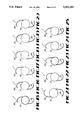
- FIGS. 4-25 are anterior plan view of alternative embodiments of IOL's made in accordance with the methods of the present invention.
- FIG. 26 is a cross-section of a first embodiment of the haptic made in accordance with the methods of the present invention taken at line 26--26 in FIG. 1.
- FIG. 27 is a longitudinal cross-section of an end portion of the first embodiment of the haptic of the present invention taken perpendicularly to the cross-section illustrated in FIG. 26 at line 27--27.
- FIG. 28 is a cross-section of a second embodiment of the haptic made in accordance with the methods of the present invention similar to FIG. 26.
- FIG. 29 is a longitudinal cross-section of an end portion of the second embodiment of the haptic of the present invention taken perpendicularly to the cross-section illustrated in FIG. 28 at line 29--29.
- IOL 1 includes an optic 10 and at least one haptic 20.
- haptics 20 may be configured in any of a number of ways and the optic 10 may have any of a number of closed-curve shapes, such as a circle, an oval or an ellipse.
- FIGS. 1, 2 and 4-25 several suitable optics 10 and haptics 20 configurations are illustrated in FIGS. 1, 2 and 4-25, other suitable shapes, sizes and configurations may also be used.
- Optic 10 has anterior face 13, posterior face 15 and peripheral edge 17.
- Optic 10 may be made of any suitable, biocompatible transparent plastic, such as PMMA, polycarbonate and copolymers of esters of acrylic acid and methacrylic acid.
- Optic 10 is preferably between 4.50 millimeters (mm) and 7.00 mm across.
- Haptics 20 are formed separately from optic 10 by injection molding, extrusion, thermal-drawing or any other suitable method.
- Haptic 20 may be of any suitable cross-sectional shape, such as round, as illustrated in FIGS. 26 and 27, rectangular with rounded corners, as illustrated in FIGS. 28 and 29, oval, elliptical, hexagonal or other geometric shape and is preferably smooth and at least end portion 21 of haptic 20 to be attached to optic 10 must be a colored material.
- haptic 20 may have a colored core 30 surrounded by a clear sheath 40. The use of core 30 surrounded by sheath 40 helps to minimize any possible leaching of the pigment used to color core 30 from haptic 20.
- Round haptic 20 (illustrated in FIGS. 26 and 27) generally has a diameter of approximately between 0.105 and 0.175 mm, with between approximately 0.127 and 0.152 mm being preferred, and the diameter of core 30 may be anywhere within the same range as the diameter of haptic 20.
- Rectangular haptic 20 (illustrated in FIGS. 28 and 29) preferably has a width of between approximately 0.11 and 0.14 mm and a height of approximately between 0.14 and 0.16 mm, for example, 0.127 mm wide by 0.152 mm high with the dimensions of core 30 approximating the overall dimensions of haptic 20.
- Haptic 20 may be made of any of a number of thermoplastics such as PMMA, polypropylene, polyimides and polyvinylidene difluoride and may be either different from or the same material as used in optic 10. If the material used to form haptic 20 is naturally non-colored, the material must either include a pigment, a dye or be combined with a colored material.
- a suitable haptic material is available from Rohm and Haas under the tradename VS100 which, upon adding copper phthalocyanine, gives the raw material necessary for forming colored haptics 20.
- Other preferred haptic materials include PMMA with a copper phthalocyanine-doped core 30 and blue polypropylene.
- the laser (not shown) used to weld haptic 20 to optic 10 must emit radiation in the visible spectrum, approximately between 400 and 700 nanometers (nm) and is preferably a continuous wave (CW) laser. Visible wavelength laser energy will be at least partially absorbed by the colored haptic material, regardless of the specific wavelength of energy used or the color of haptic 20; however, it is preferable that the laser energy spectrum used be matched with the absorption spectrum of the material used to form haptic 20 or core 30. For example, if haptic 20 or core 30 is blue, it is generally preferred that the visible laser energy spectrum have some wavelengths in the deep blue, green or red portions of the visible spectrum absorbed by haptic 20 or core 30. Such a spectrum is emitted from Krypton, Argon or tunable dye lasers for a copper phthalocyanine-doped PMMA haptic 20.
- CW continuous wave
- hole 12 in optic 10 may be made in any suitable manner and be formed either after optic 10 has been formed, such as by drilling, or optic 10 may be formed with hole 12 pre-formed.
- Hole 12 is preferably smooth and less than 1 mm deep and should be only slightly larger in diameter than the maximum cross-sectional dimension of haptic 20 so that haptic 20 fits snugly within hole 12.
- end portion 21 of haptic 20 is inserted fully into hole 12.
- the laser (not shown) is aimed at end portion 21 of haptic 20 within hole 12 in optic 10 and fired.
- the laser energy is fully transmitted through transparent optic 10 without damaging optic 10 while the pigment or dye in haptic 20 or in core 30 absorbs the laser energy and heats to a temperature sufficient to melt end portion 21 and fuse end portion 21 to optic 10 within hole 12.
- the laser energy level needed to fuse haptic 20 and optic 10 will vary with the materials used for optic 10, haptic 20 and core 30, but generally will be less than 5 watts.
- haptic 20 is made from the colored VS100 material (PMMA with a copper phthalocyanine-doped core) and optic 10 is made from PMMA
- the laser output required to fuse haptic 20 and optic 10 is approximately between 1/4 and 2 watts with a laser exposure time of approximately between 1 and 3 seconds when a laser spot size of approximately 100 microns is used.
Abstract
Description
Claims (55)
Priority Applications (10)
| Application Number | Priority Date | Filing Date | Title |
|---|---|---|---|
| US07/833,872 US5252262A (en) | 1992-02-11 | 1992-02-11 | Method of attaching a haptic to an optic of an intraocular lens |
| AU15311/92A AU663081B2 (en) | 1992-02-11 | 1992-03-06 | Method of attaching a haptic to an optic of an intraocular lens |
| CA002125852A CA2125852C (en) | 1992-02-11 | 1992-03-06 | Method of attaching a haptic to an optic of an intraocular lens |
| EP92907443A EP0626833B1 (en) | 1992-02-11 | 1992-03-06 | Method of attaching a haptic to an optic of an intraocular lens |
| PCT/US1992/001613 WO1993015692A1 (en) | 1992-02-11 | 1992-03-06 | Method of attaching a haptic to an optic of an intraocular lens |
| AT92907443T ATE160496T1 (en) | 1992-02-11 | 1992-03-06 | METHOD FOR ATTACHING A MOUNTING BRACKET TO THE OPTICS OF AN INTRACULAR LENS |
| JP4507415A JPH07503148A (en) | 1992-02-11 | 1992-03-06 | How to attach a haptic to the optical element of an intraocular lens |
| DE69223331T DE69223331T2 (en) | 1992-02-11 | 1992-03-06 | METHOD FOR ATTACHING A FASTENING BRACKET TO THE OPTICS OF AN INTRACULAR LENS |
| KR1019940702792A KR950700039A (en) | 1992-02-11 | 1992-03-06 | METHOD OF ATTACHING A HAPTIC TO AN OPTIC OF AN INTRAOCULAR LENS |
| TW081101965A TW210955B (en) | 1992-02-11 | 1992-03-16 |
Applications Claiming Priority (1)
| Application Number | Priority Date | Filing Date | Title |
|---|---|---|---|
| US07/833,872 US5252262A (en) | 1992-02-11 | 1992-02-11 | Method of attaching a haptic to an optic of an intraocular lens |
Publications (1)
| Publication Number | Publication Date |
|---|---|
| US5252262A true US5252262A (en) | 1993-10-12 |
Family
ID=25265489
Family Applications (1)
| Application Number | Title | Priority Date | Filing Date |
|---|---|---|---|
| US07/833,872 Expired - Lifetime US5252262A (en) | 1992-02-11 | 1992-02-11 | Method of attaching a haptic to an optic of an intraocular lens |
Country Status (10)
| Country | Link |
|---|---|
| US (1) | US5252262A (en) |
| EP (1) | EP0626833B1 (en) |
| JP (1) | JPH07503148A (en) |
| KR (1) | KR950700039A (en) |
| AT (1) | ATE160496T1 (en) |
| AU (1) | AU663081B2 (en) |
| CA (1) | CA2125852C (en) |
| DE (1) | DE69223331T2 (en) |
| TW (1) | TW210955B (en) |
| WO (1) | WO1993015692A1 (en) |
Cited By (15)
| Publication number | Priority date | Publication date | Assignee | Title |
|---|---|---|---|---|
| US5523029A (en) * | 1995-02-01 | 1996-06-04 | Alcon Laboratories, Inc. | Method of attaching a haptic to an optic of an intraocular lens |
| US5770125A (en) * | 1995-11-27 | 1998-06-23 | Mentor Corporation | Haptic attachment system for intraocular lenses using diode laser |
| US5902523A (en) * | 1996-06-26 | 1999-05-11 | Allergan | IOLs and production methods for same |
| US6159242A (en) * | 1998-01-16 | 2000-12-12 | Menicon Co., Ltd. | Intraocular lens having support member fixed in hole formed in insert embedded in lens body, and method of producing the same |
| WO2000059365A3 (en) * | 1999-04-05 | 2001-02-22 | Jessen Wesley Corp | Biomedical devices with polyimide coating |
| US6235055B1 (en) | 1999-08-09 | 2001-05-22 | Milton W. Chu | Intraocular lens having colored haptics for anterior/posterior orientation, and method for implanting it |
| US6251312B1 (en) * | 1996-10-30 | 2001-06-26 | Allergan | Production methods for intraocular lenses with high pull strength fixation members |
| WO2002038677A2 (en) * | 2000-11-10 | 2002-05-16 | Gentex Corporation | Visibly transparent dyes for through-transmission laser welding |
| US20030062117A1 (en) * | 2001-09-28 | 2003-04-03 | Frieder Leonard P. | Rimless spectacles and method for making the same |
| US20030150543A1 (en) * | 2002-01-15 | 2003-08-14 | Hartley Scott M. | Quality management system for pre-processed workpiece |
| US20040034416A1 (en) * | 2001-09-06 | 2004-02-19 | Preussner Paul Rolf | Stiffenable capsule clamping ring |
| US20040240374A1 (en) * | 2003-05-30 | 2004-12-02 | Hideharu Tajima | Optical data recording medium and method for reproducing recorded data |
| US20080179077A1 (en) * | 2005-06-07 | 2008-07-31 | Abb Research Ltd | High-voltage bushing |
| US20110251685A1 (en) * | 2010-04-09 | 2011-10-13 | Chu Milton W | Intraocular lenses with high contrast haptics, materials, and methods |
| US9277988B1 (en) | 2013-03-15 | 2016-03-08 | Milton W. Chu | Intraocular lenses with quantum dots |
Citations (9)
| Publication number | Priority date | Publication date | Assignee | Title |
|---|---|---|---|---|
| JPS63206240A (en) * | 1987-02-20 | 1988-08-25 | 株式会社メニコン | Method and apparatus for producing intraocular lens |
| US4786445A (en) * | 1985-07-11 | 1988-11-22 | Allergan, Inc. | Method of attaching a fixation member to an intraocular lens |
| US4834749A (en) * | 1987-12-24 | 1989-05-30 | Texceed Corporation | Haptic attachment method and assembly |
| US4834751A (en) * | 1985-12-04 | 1989-05-30 | Allergan, Inc. | Staking ring for soft IOL |
| US4843209A (en) * | 1987-11-05 | 1989-06-27 | Dennis T. Grendahl | Method and apparatus for laser staking |
| US4863539A (en) * | 1987-11-06 | 1989-09-05 | Optical Radiation Corporation | Haptic attachment for intraocular lenses |
| US4894062A (en) * | 1985-12-04 | 1990-01-16 | Allergan, Inc. | Staking anchor for soft IOL |
| US5074942A (en) * | 1990-05-15 | 1991-12-24 | Texceed Corporation | Method for making intraocular lens with integral colored haptics |
| US5118452A (en) * | 1991-04-05 | 1992-06-02 | Nestle S.A. | Method of attaching a haptic to an optic of an intraocular lens |
Family Cites Families (3)
| Publication number | Priority date | Publication date | Assignee | Title |
|---|---|---|---|---|
| CA1278447C (en) * | 1985-07-11 | 1991-01-02 | Vladimir Portnoy | Iol and method of attaching a fixation member to an optic |
| CA2021582A1 (en) * | 1989-08-30 | 1991-03-01 | Harris A. Goldberg | Scanning tunneling microscope utilizing optical fluorescent for reading |
| US5089180A (en) * | 1989-08-31 | 1992-02-18 | Iolab Corporation | Method of preparing composite single-piece intraocular lenses with colored haptics |
-
1992
- 1992-02-11 US US07/833,872 patent/US5252262A/en not_active Expired - Lifetime
- 1992-03-06 AT AT92907443T patent/ATE160496T1/en not_active IP Right Cessation
- 1992-03-06 AU AU15311/92A patent/AU663081B2/en not_active Expired
- 1992-03-06 EP EP92907443A patent/EP0626833B1/en not_active Expired - Lifetime
- 1992-03-06 JP JP4507415A patent/JPH07503148A/en active Pending
- 1992-03-06 WO PCT/US1992/001613 patent/WO1993015692A1/en active IP Right Grant
- 1992-03-06 CA CA002125852A patent/CA2125852C/en not_active Expired - Lifetime
- 1992-03-06 DE DE69223331T patent/DE69223331T2/en not_active Expired - Lifetime
- 1992-03-06 KR KR1019940702792A patent/KR950700039A/en not_active Application Discontinuation
- 1992-03-16 TW TW081101965A patent/TW210955B/zh active
Patent Citations (9)
| Publication number | Priority date | Publication date | Assignee | Title |
|---|---|---|---|---|
| US4786445A (en) * | 1985-07-11 | 1988-11-22 | Allergan, Inc. | Method of attaching a fixation member to an intraocular lens |
| US4834751A (en) * | 1985-12-04 | 1989-05-30 | Allergan, Inc. | Staking ring for soft IOL |
| US4894062A (en) * | 1985-12-04 | 1990-01-16 | Allergan, Inc. | Staking anchor for soft IOL |
| JPS63206240A (en) * | 1987-02-20 | 1988-08-25 | 株式会社メニコン | Method and apparatus for producing intraocular lens |
| US4843209A (en) * | 1987-11-05 | 1989-06-27 | Dennis T. Grendahl | Method and apparatus for laser staking |
| US4863539A (en) * | 1987-11-06 | 1989-09-05 | Optical Radiation Corporation | Haptic attachment for intraocular lenses |
| US4834749A (en) * | 1987-12-24 | 1989-05-30 | Texceed Corporation | Haptic attachment method and assembly |
| US5074942A (en) * | 1990-05-15 | 1991-12-24 | Texceed Corporation | Method for making intraocular lens with integral colored haptics |
| US5118452A (en) * | 1991-04-05 | 1992-06-02 | Nestle S.A. | Method of attaching a haptic to an optic of an intraocular lens |
Cited By (43)
| Publication number | Priority date | Publication date | Assignee | Title |
|---|---|---|---|---|
| WO1996023456A1 (en) * | 1995-02-01 | 1996-08-08 | Alcon Laboratories, Inc. | Method of attaching a haptic to an optic of an intraocular lens |
| US5523029A (en) * | 1995-02-01 | 1996-06-04 | Alcon Laboratories, Inc. | Method of attaching a haptic to an optic of an intraocular lens |
| US5770125A (en) * | 1995-11-27 | 1998-06-23 | Mentor Corporation | Haptic attachment system for intraocular lenses using diode laser |
| US6118913A (en) * | 1995-11-27 | 2000-09-12 | Ciba Vision Corporation | Apparatus for haptic attachment for intraocular lenses using diode laser |
| US5902523A (en) * | 1996-06-26 | 1999-05-11 | Allergan | IOLs and production methods for same |
| US6053944A (en) * | 1996-06-26 | 2000-04-25 | Tran; Duc Q. | IOLs with improved fixation strengths for fixation members |
| US6156241A (en) * | 1996-06-26 | 2000-12-05 | Allergan | IOLs and production methods for same |
| US6251312B1 (en) * | 1996-10-30 | 2001-06-26 | Allergan | Production methods for intraocular lenses with high pull strength fixation members |
| US6159242A (en) * | 1998-01-16 | 2000-12-12 | Menicon Co., Ltd. | Intraocular lens having support member fixed in hole formed in insert embedded in lens body, and method of producing the same |
| US6942695B1 (en) | 1999-04-05 | 2005-09-13 | Wessley-Jessen Corporation | Biomedical devices with polyimide coating |
| WO2000059365A3 (en) * | 1999-04-05 | 2001-02-22 | Jessen Wesley Corp | Biomedical devices with polyimide coating |
| US6235055B1 (en) | 1999-08-09 | 2001-05-22 | Milton W. Chu | Intraocular lens having colored haptics for anterior/posterior orientation, and method for implanting it |
| WO2002038677A3 (en) * | 2000-11-10 | 2002-07-11 | Gentex Corp | Visibly transparent dyes for through-transmission laser welding |
| US20080047668A1 (en) * | 2000-11-10 | 2008-02-28 | Sallavanti Robert A | Visibly transparent dyes for through-transmission laser welding |
| US20030196761A1 (en) * | 2000-11-10 | 2003-10-23 | Sallavanti Robert A. | Visibly transparent dyes for through-transmission laser welding |
| US6656315B2 (en) * | 2000-11-10 | 2003-12-02 | Gentex Corporation | Visibly transparent dyes for through-transmission laser welding |
| US7276136B2 (en) | 2000-11-10 | 2007-10-02 | Gentex Corporation | Visibly transparent dyes for through-transmission laser welding |
| WO2002038677A2 (en) * | 2000-11-10 | 2002-05-16 | Gentex Corporation | Visibly transparent dyes for through-transmission laser welding |
| US20040244905A1 (en) * | 2000-11-10 | 2004-12-09 | Sallavanti Robert A. | Visibly transparent dyes for through-transmission laser welding |
| US6911262B2 (en) | 2000-11-10 | 2005-06-28 | Gentex Corporation | Visibly transparent dyes for through-transmission laser welding |
| US20040034416A1 (en) * | 2001-09-06 | 2004-02-19 | Preussner Paul Rolf | Stiffenable capsule clamping ring |
| US7001428B2 (en) * | 2001-09-06 | 2006-02-21 | Paul Rolf Preussner | Stiffenable capsule clamping ring |
| US20030062117A1 (en) * | 2001-09-28 | 2003-04-03 | Frieder Leonard P. | Rimless spectacles and method for making the same |
| US6752893B2 (en) | 2001-09-28 | 2004-06-22 | Gentex Corporation | Rimless spectacles and method for making the same |
| US6770158B2 (en) | 2002-01-15 | 2004-08-03 | Gentex Corporation | Quality management system for pre-processed workpiece |
| US7344774B2 (en) | 2002-01-15 | 2008-03-18 | Gentex Corporation | Pre-processed workpiece having a surface deposition of absorber dye rendering the workpiece weld-enabled |
| US7201963B2 (en) | 2002-01-15 | 2007-04-10 | Gentex Corporation | Pre-processed workpiece having a surface deposition of absorber dye rendering the workpiece weld-enabled |
| US20070184279A1 (en) * | 2002-01-15 | 2007-08-09 | Gentex Corporation | Pre-processed workpiece having a surface deposition of absorber dye rendering the workpiece weld-enabled |
| US20040038023A1 (en) * | 2002-01-15 | 2004-02-26 | Hartley Scott M. | Pre-processed workpiece having a surface deposition of absorber dye rendering the workpiece weld-enabled |
| US20030150543A1 (en) * | 2002-01-15 | 2003-08-14 | Hartley Scott M. | Quality management system for pre-processed workpiece |
| US20100103807A1 (en) * | 2003-05-30 | 2010-04-29 | Sharp Kabushiki Kaisha | Optical data recording medium and method for reproducing recorded data |
| US20080130476A1 (en) * | 2003-05-30 | 2008-06-05 | Sharp Kabushiki Kaisha | Optical data recording medium and method for reproducing recorded data |
| US20040240374A1 (en) * | 2003-05-30 | 2004-12-02 | Hideharu Tajima | Optical data recording medium and method for reproducing recorded data |
| US20100254247A1 (en) * | 2003-05-30 | 2010-10-07 | Sharp Kabushiki Kaisha | Optical data recording medium and method for reproducing recorded data |
| US20100329106A1 (en) * | 2003-05-30 | 2010-12-30 | Sharp Kabushiki Kaisha | Optical data recording medium and method for reproducing recorded data |
| US20110044148A1 (en) * | 2003-05-30 | 2011-02-24 | Sharp Kabushiki Kaisha | Optical data recording medium and method for reproducing recorded data |
| US8194513B2 (en) | 2003-05-30 | 2012-06-05 | Sharp Kabushiki Kaisha | Optical data recording medium and method for reproducing recorded data |
| US8576688B2 (en) | 2003-05-30 | 2013-11-05 | Sharp Kabushiki Kaisha | Optical data recording medium and method for reproducing recorded data |
| US9111554B2 (en) * | 2003-05-30 | 2015-08-18 | Sharp Kabushiki Kaisha | Optical data recording medium and method for reproducing recorded data |
| US20080179077A1 (en) * | 2005-06-07 | 2008-07-31 | Abb Research Ltd | High-voltage bushing |
| US20110251685A1 (en) * | 2010-04-09 | 2011-10-13 | Chu Milton W | Intraocular lenses with high contrast haptics, materials, and methods |
| US8308800B2 (en) * | 2010-04-09 | 2012-11-13 | Chu Milton W | Intraocular lenses with high contrast haptics, materials, and methods |
| US9277988B1 (en) | 2013-03-15 | 2016-03-08 | Milton W. Chu | Intraocular lenses with quantum dots |
Also Published As
| Publication number | Publication date |
|---|---|
| DE69223331D1 (en) | 1998-01-08 |
| DE69223331T2 (en) | 1998-03-19 |
| JPH07503148A (en) | 1995-04-06 |
| AU1531192A (en) | 1993-09-03 |
| CA2125852A1 (en) | 1993-08-19 |
| EP0626833A1 (en) | 1994-12-07 |
| KR950700039A (en) | 1995-01-16 |
| CA2125852C (en) | 2001-05-15 |
| WO1993015692A1 (en) | 1993-08-19 |
| EP0626833B1 (en) | 1997-11-26 |
| TW210955B (en) | 1993-08-11 |
| AU663081B2 (en) | 1995-09-28 |
| ATE160496T1 (en) | 1997-12-15 |
Similar Documents
| Publication | Publication Date | Title |
|---|---|---|
| US5252262A (en) | Method of attaching a haptic to an optic of an intraocular lens | |
| US5523029A (en) | Method of attaching a haptic to an optic of an intraocular lens | |
| US5118452A (en) | Method of attaching a haptic to an optic of an intraocular lens | |
| US5141507A (en) | Soft intraocular lens | |
| US6342073B1 (en) | Intraocular lens for posterior vaulting | |
| US4642114A (en) | Posterior chamber intraocular lens | |
| ES2281198T3 (en) | CONVERSION SYSTEM OF A CRYSTALLINE FOR TELEDIOPTRIC OR DIFFACTIVE CONFIGURATIONS. | |
| US4790846A (en) | Haptic to optic attachment for a soft IOL | |
| EP0227357B1 (en) | Intraocular lens and method of manufacture | |
| US4786445A (en) | Method of attaching a fixation member to an intraocular lens | |
| GB2181355A (en) | Lens implant | |
| CN101522132A (en) | Corneal implants and methods and systems for placement | |
| JPH1189861A (en) | Intraocular lens transplant | |
| US4888013A (en) | Haptic to optic attachment for a soft iol | |
| US6036683A (en) | Process and apparatus for changing the curvature of the cornea | |
| US5171268A (en) | Haptic to optic attachment for a soft iol | |
| US4880426A (en) | Haptic to optic attachment for a soft IOL | |
| US20230210656A1 (en) | Accommodative intraocular lens | |
| US5250235A (en) | Method of making laser-welded intraocular lenses | |
| US4938767A (en) | Haptic to optic attachment for a soft iol | |
| US20090289382A1 (en) | System and method for modifying characteristics of a contact lens utilizing an ultra-short pulsed laser | |
| US7001428B2 (en) | Stiffenable capsule clamping ring | |
| EP0536454A1 (en) | Assembly method for intraocular lenses | |
| JPS63189147A (en) | Production of intraocular lens |
Legal Events
| Date | Code | Title | Description |
|---|---|---|---|
| AS | Assignment |
Owner name: NESTLE S.A., SWITZERLAND Free format text: ASSIGNMENT OF ASSIGNORS INTEREST.;ASSIGNOR:PATEL, ANILBHAI S.;REEL/FRAME:006018/0023 Effective date: 19920211 |
|
| STCF | Information on status: patent grant |
Free format text: PATENTED CASE |
|
| FPAY | Fee payment |
Year of fee payment: 4 |
|
| FEPP | Fee payment procedure |
Free format text: PAYOR NUMBER ASSIGNED (ORIGINAL EVENT CODE: ASPN); ENTITY STATUS OF PATENT OWNER: LARGE ENTITY Free format text: PAYER NUMBER DE-ASSIGNED (ORIGINAL EVENT CODE: RMPN); ENTITY STATUS OF PATENT OWNER: LARGE ENTITY |
|
| FPAY | Fee payment |
Year of fee payment: 8 |
|
| FPAY | Fee payment |
Year of fee payment: 12 |