US5253986A - Impeller-type pump system - Google Patents
Impeller-type pump system Download PDFInfo
- Publication number
- US5253986A US5253986A US07/882,454 US88245492A US5253986A US 5253986 A US5253986 A US 5253986A US 88245492 A US88245492 A US 88245492A US 5253986 A US5253986 A US 5253986A
- Authority
- US
- United States
- Prior art keywords
- impeller
- pump chamber
- chamber
- pump
- housing
- Prior art date
- Legal status (The legal status is an assumption and is not a legal conclusion. Google has not performed a legal analysis and makes no representation as to the accuracy of the status listed.)
- Expired - Lifetime
Links
Images


Classifications
-
- F—MECHANICAL ENGINEERING; LIGHTING; HEATING; WEAPONS; BLASTING
- F04—POSITIVE - DISPLACEMENT MACHINES FOR LIQUIDS; PUMPS FOR LIQUIDS OR ELASTIC FLUIDS
- F04D—NON-POSITIVE-DISPLACEMENT PUMPS
- F04D29/00—Details, component parts, or accessories
- F04D29/04—Shafts or bearings, or assemblies thereof
- F04D29/046—Bearings
- F04D29/047—Bearings hydrostatic; hydrodynamic
-
- F—MECHANICAL ENGINEERING; LIGHTING; HEATING; WEAPONS; BLASTING
- F04—POSITIVE - DISPLACEMENT MACHINES FOR LIQUIDS; PUMPS FOR LIQUIDS OR ELASTIC FLUIDS
- F04D—NON-POSITIVE-DISPLACEMENT PUMPS
- F04D13/00—Pumping installations or systems
- F04D13/02—Units comprising pumps and their driving means
- F04D13/021—Units comprising pumps and their driving means containing a coupling
- F04D13/024—Units comprising pumps and their driving means containing a coupling a magnetic coupling
- F04D13/026—Details of the bearings
-
- F—MECHANICAL ENGINEERING; LIGHTING; HEATING; WEAPONS; BLASTING
- F04—POSITIVE - DISPLACEMENT MACHINES FOR LIQUIDS; PUMPS FOR LIQUIDS OR ELASTIC FLUIDS
- F04D—NON-POSITIVE-DISPLACEMENT PUMPS
- F04D13/00—Pumping installations or systems
- F04D13/02—Units comprising pumps and their driving means
- F04D13/021—Units comprising pumps and their driving means containing a coupling
- F04D13/024—Units comprising pumps and their driving means containing a coupling a magnetic coupling
- F04D13/027—Details of the magnetic circuit
-
- F—MECHANICAL ENGINEERING; LIGHTING; HEATING; WEAPONS; BLASTING
- F04—POSITIVE - DISPLACEMENT MACHINES FOR LIQUIDS; PUMPS FOR LIQUIDS OR ELASTIC FLUIDS
- F04D—NON-POSITIVE-DISPLACEMENT PUMPS
- F04D29/00—Details, component parts, or accessories
- F04D29/04—Shafts or bearings, or assemblies thereof
- F04D29/041—Axial thrust balancing
- F04D29/0413—Axial thrust balancing hydrostatic; hydrodynamic thrust bearings
-
- F—MECHANICAL ENGINEERING; LIGHTING; HEATING; WEAPONS; BLASTING
- F04—POSITIVE - DISPLACEMENT MACHINES FOR LIQUIDS; PUMPS FOR LIQUIDS OR ELASTIC FLUIDS
- F04D—NON-POSITIVE-DISPLACEMENT PUMPS
- F04D29/00—Details, component parts, or accessories
- F04D29/04—Shafts or bearings, or assemblies thereof
- F04D29/046—Bearings
- F04D29/0465—Ceramic bearing designs
-
- F—MECHANICAL ENGINEERING; LIGHTING; HEATING; WEAPONS; BLASTING
- F04—POSITIVE - DISPLACEMENT MACHINES FOR LIQUIDS; PUMPS FOR LIQUIDS OR ELASTIC FLUIDS
- F04D—NON-POSITIVE-DISPLACEMENT PUMPS
- F04D29/00—Details, component parts, or accessories
- F04D29/04—Shafts or bearings, or assemblies thereof
- F04D29/046—Bearings
- F04D29/049—Roller bearings
Definitions
- This invention generally relates to the art of centrifugal pumps and, particularly, to an impeller-type pump system which is magnetically driven.
- Centrifugal liquid pumps are used in many environments or applications. Such devices conventionally include a housing defining a pump chamber or cavity within which an impeller assembly is rotated.
- the impeller assembly is mounted on a shaft rotatably journalled within the housing and including radially projecting impeller blades for drawing fluid into an inlet of the housing and discharging through an outlet.
- Bearings are provided about the impeller shaft, usually behind the impeller, to journal the shaft within the housing.
- a pressure balance chamber may be provided behind the impeller to reduce axial thrust loads, thereby increasing the life or reducing the size or quantity of the thrust bearings.
- Such pump systems commonly are of a seal type design and may employ single, tandem or double seal systems along a shaft as is deemed desirable in particular applications. These sealed pumps attempt, as much as possible, to contain the process fluid and to prevent fluid entry into the gear box or other driving components in gear driven high speed units.
- sealless pumps that is, pumps without shaft seals
- These pumps typically are considered as being desirable when used with fluids which are hazardous, polluting or expensive.
- sealless pumps are more expensive and less efficient than the more common pumps described above, but these disadvantages are considered the price to be paid for a clean environment.
- mainline electric driven sealless pump technology can be broken down into two concepts, namely a canned electric motor driven pump and a magnetic coupling driven pump.
- An inherent limitation of the canned motor pump concerns the skin friction loss of the submerged drive motor which imposes a viable speed limit, i.e. a head capability limit. Skin friction loss is the drag or resistance of the process fluid on the motor rotor.
- Series staging or series arranged canned motor pump components constitute complex and costly means of circumventing this limitation and are infrequently utilized.
- modern design utilizing potent rare earth permanent magnets incurs relatively low skin friction loss in magnetic drives, thereby allowing practical high speed operation, i.e. high head design. Concentric arrangements of magnets generally are used, particularly for high torque applications, i.e. greater than one horsepower.
- Permanent magnet driven pumps may be of the more common concentric magnetic geometry or may be of a less common axially facing magnetic geometry. Concentric magnetic arrangements have the advantage of producing only torque forces while the axial geometry imposes axially attractive forces on the drive and driven shafts, in addition to the prime objective of drive torque.
- the need to handle substantial axial thrust could impose serious disadvantages in pump design, particularly in the driven half of the magnetic coupling where the process fluid must serve as a lubricant.
- this disadvantage can be compensated for if the axial magnetic geometry is used in conjunction with a hydraulic thrust balance system where available hydraulic force easily accommodates the magnetic attraction force.
- Such thrust balance systems are shown in U.S. Pat. Nos. 4,867,633 to Gravelle, dated Sep. 19, 1989, and 5,061,151 to Steiger, dated Oct. 29, 1991, both of which are assigned to Sundstrand Corporation.
- This invention is directed to various improvements in a sealless centrifugal pump of the impeller-type which employs an axial permanent magnet geometry in conjunction with a hydraulic thrust balance system.
- An object, therefore, of the invention is to provide a new and improved impeller-type pump system incorporating axially facing magnets, the system being hydraulically thrust balanced.
- the impeller-type pump system includes housing means having interior wall means defining a pump chamber and a fluid inlet communicating with the chamber. Impeller means are rotatably mounted in the pump chamber downstream of the inlet.
- the impeller means include an inducer stage forward of a centrifugal impeller stage.
- the invention contemplates that the impeller means not be rotatably mounted on a conventional bearing-supported shaft means, but that the impeller means be rotatably mounted in the pump chamber by radial bearing means disposed outside the impeller means, the bearing means being sandwiched between the impeller means and the interior wall means of the pump chamber.
- the impeller means include a hub behind the centrifugal impeller stage.
- the bearing means include first and second bearings, one of the bearings being located about the hub and the other bearing being located forwardly thereof.
- the hub mounts an axially facing magnetic drive coupling, with the one bearing located thereabout to minimize overall parasitic drag caused by fluid friction.
- the impeller means, hub and magnetic coupling comprise a unitary structure supported within the pump chamber by the outside bearing means. Therefore, the impeller structure can be readily pressure balanced.
- Another feature of the invention is the provision of ball bearing means mounted in an axially rearwardly opening recess means in the impeller means.
- the ball bearing means bear against a closure means behind the impeller means, at least during start-up of the pump.
- the ball bearing means include a plurality of ball bearings radially captured by sidewalls of the recess means, the sidewalls diverging away from the closure means, whereby the ball bearings move away from the closure means under centrifugal force in response to rotation of the impeller means.
- the recess means is cup-shaped and located concentric with the axis of rotation of the impeller means.
- a further feature of the invention is providing the closure means behind the impeller means as a ceramic barrier.
- the ceramic barrier is formed by a pair of thin, juxtaposed discs.
- the discs are fabricated of zirconia ceramic material, and the discs are heat shrunk within a circular opening at the rear of the pump chamber.
- FIG. 1 is an axial section through a magnetic drive pump incorporating the concepts of the invention, the pump being attached to a gearbox and drive motor;
- FIG. 2 is an axial section through the magnetic drive pump removed from the gearbox
- FIG. 3 is an axial elevational view of the magnetic coupling of the pump impeller assembly
- FIG. 4 is a vertical section taken generally along line 4--4 of FIG. 3;
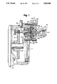
- FIG. 5 is an enlarged, fragmented axially section through the ball bearing means at the rear of the impeller assembly.
- FIG. 1 shows the pump system incorporated with an attached high speed gearbox, generally designated 11, and a drive motor, generally designated 12, and
- FIG. 2 shows the pump system removed from gearbox 11 for clarity. Consequently, like numerals are applied in both FIGS. 1 and 2 to designate like components of impeller-type centrifugal pump system 10.
- drive shaft 14 has an integral gear portion 14a in mesh with a gear 11a within gearbox 11.
- Gear 11a is fixed to a drive shaft 12a projecting into the gearbox from drive motor 12.
- the shaft 14 may be driven at speeds ranging from 13,000 to 32,000 rpm.
- pump system 10 includes a front housing 16 defining a main pump chamber or cavity having a forward chamber portion 18 and a rear chamber portion 20.
- front housing 16 is clamped to a gearbox housing 22 by bolts 24, sandwiching a rear housing 26 of the centrifugal pump system therebetween.
- a ring seal 29 is disposed between the front and rear housings.
- Front housing 16 preferably is fabricated of corrosion resistant steel, such as Series 300 stainless steel.
- Impeller means are rotatably mounted within the pump chamber of front housing 16 and include a hub 32 with helical inducer blades 34a and main impeller blades 34b projecting radially outwardly from the hub into forward chamber portion 18 and rear chamber portion 20, respectively.
- the impeller functions to draw fluid into an inlet 36 of front housing 16 and discharges through an outlet 38 of the housing. Therefore, the impeller pump is a two-stage pump, in that impeller blades 34a within forward chamber portion 18 define an inducer stage and impeller blades 34b within rear chamber portion 20 define a centrifugal impeller stage.
- Impeller 30 is part of an impeller assembly in which the rear of hub 32 is fixed to an impeller plate 40, as by welds 42.
- the impeller rear shroud plate is fixed on a magnet hub or casing 44, as by a peripheral weld 46. Therefore, the impeller assembly is a unitary rigid, rotatable structure.
- Magnet hub or casing 44 includes an integral thin wall 44a to completely encase its magnet assembly, described hereinafter, and thereby protect the magnet assembly from process fluid.
- the impeller-type centrifugal pump includes a system for pressure balancing the impeller assembly by communicating the inlet side of impeller 30 to the back side of the impeller assembly. Hydraulic thrust balance is achieved and continuously maintained by axial movement of the impeller to modulate an axial gap 47 between plate 40 and housing 16. Leakage flow from the impeller outlet passes through gap 47, through bearing slots 65, radially inward between thin wall 44a and ceramic disc 82b, and returns to the impeller inlet through passages 52 and 48. This controls the magnitude of pressure acting on the backside of the impeller whereby an outward force resulting therefrom counterbalances an inward thrust force from pressure acting on the front of the impeller.
- Radial passages 48 in impeller hub 32 communicate with an axial passage 50 in the hub and which, in turn, communicates with an axial passage 52 in magnet hub or casing 44 leading to the back side of the impeller assembly. Therefore, due to the pressure balancing of the impeller assembly, axial thrust loads on the impeller assembly are eliminated.
- the impeller assembly including impeller 30, is rotated by an axially facing permanent magnet arrangement or magnetic coupling which includes an axially facing drive magnet assembly, generally designated 54, and a driven magnet assembly, generally designated 56.
- Drive magnet assembly 54 is mounted within a magnet hub 58 fixed to drive shaft 14.
- the drive shaft is rotatably mounted within rear housing 26 by appropriate bearing means 60 secured within the rear housing by a locking ring 62. Therefore, as shaft 14 rotates drive magnet assembly 54, the drive magnet assembly is flux coupled to driven magnet assembly 56 to rotate the impeller assembly including impeller 30.
- the invention contemplates that the unitary impeller assembly, including impeller 30 and driven magnet assembly 56, be rotatably mounted within the pump chamber of front housing 16 by radial bearing means located outside of and surrounding the impeller assembly. More particularly, the bearing means include a first annular bearing 64 surrounding magnet hub 44 and a second annular bearing 66 surrounding impeller 30. With first bearing 64 surrounding the magnet hub, the bearing is outside driven magnet assembly 56 and thereby minimizes parasitic drag. A ring seal 67 surrounds the outside of first bearing 64, between the bearing and rear housing 26.
- Second annular bearing 66 is seated against an interior shoulder 68 of front housing 16 and bears against an impeller ring 78 fixed to the impeller, as by welds 80. With bearings 64 and 66 being located outside the impeller assembly, no centerline support shaft or centrally located bearings are required.
- the invention contemplates a novel barrier means defining a closure means for the rear of the pump chamber of the impeller assembly to provide a sealless pump and to prevent fluid from entering the drive components of the pump as well as gearbox 11. More particularly, an axially spaced pair of zirconia ceramic discs 82a and 82b are juxtaposed and disposed within a circular opening 84 defined in a retainer ring 86 sandwiched between bearing 64 and rear housing 26. A first ring seal 87a is disposed between rearward disc 82a and rear housing 26, and a second ring seal 87b is disposed between forward disc 82b and bearing 64.
- the double barrier configuration provides maximum protection against overboard leakage, even under rare circumstances such as extreme thermal shock.
- Each ceramic disc 82a, 82b possesses sufficient strength to, alone, contain the pump hydrostatic design pressure.
- the retainer ring 86 is heated then shrunk onto ceramic discs 82a and 82b to develop compressive stresses to resist tensile stresses caused by pressure loading. This minimizes the ceramic thickness because compressive strength typically is much greater than tensile strength. By minimizing the thickness of the ceramic discs, maximum torque is achieved due to the reduced gap between magnet assemblies 54 and 56.
- the thicknesses and axial spacing of the ceramic discs are chosen so that the fluid side disc 82b will rupture if overpressurized or damaged. In other words, ceramic disc 82b may be thinner than ceramic disc 82a.
- a radial port 88 is provided through retainer ring 86 and can be placed in communication with a leak detector which, in turn, can initiate an alarm or shutdown.
- a good barrier material for forming a closure means at the rear of the pump chamber should possess low electrical conductivity and low permeability to minimize eddy current loss and heat build-up. This consideration becomes increasingly important in high speed design because of the high rate at which flux lines cut the barrier material. Consequently, zirconia ceramic material has been chosen for the barrier discs.
- driven magnet assembly 56 is shown. However, it should be understood that drive magnet assembly 54 can be similarly constructed.
- magnet assembly 56 includes four separate pie shaped magnet segments 90 attached to a backing iron 92 by an epoxy type adhesive so that the magnet segments will not move out of place when attracted by other magnet segments.
- the magnet segments are separated by thin non-magnetic keys 94 which fit in shallow radial key slots in backing iron 92.
- the backing iron closes the magnetic flux field behind the magnets opposite from the inter-magnetic gap between drive magnet assembly 54 and driven magnet assembly 56. In the backing iron, the flux is angularly directed to the adjacent magnetic pole of different polarity. In essence, the backing iron captures or traps the magnetic field within the iron.
- the invention contemplates the provision of thrust ball bearing means mounted in an axially rearwardly opening recess means in the impeller assembly, with the barrier means defining the rear of the pump chamber, particularly, ceramic disc 82b.
- a cup-shaped recess 96 is formed in the rear face of the impeller assembly about centerline axial passage 52 through magnet hub 44.
- the recess has sidewalls 98 which diverge radially outwardly away from the barrier means defined by the ceramic disc.
- a plurality of balls 100 (such as three balls) are disposed in recess 96 and are radially captured by diverging walls 98. Clearance is provided between the array of bearing balls for fluid communication therebetween with passage 52.
- the thrust ball bearing means is provided because a critical consideration in magnetic drives is to assure that magnetic decoupling does not occur due to start up friction since this would result in a complete stall that can be rectified only by a shut down and restart.
- axially facing coupled magnets exert axial forces which are compensated for dynamically by the hydraulic thrust balance system described above, but the axial forces cause the impeller assembly to bear hard against the barrier provided by the ceramic discs.
- Start-up friction must be such that torque is within the capacity of the magnetic coupling.
- the ball pitch circle can be very small, as shown, so that rolling speeds are not excessive, and the rolling balls continuously expose new surfaces to contact.
- centrifugal force acts to preclude ball contact with the disc under steady state operating conditions. Because of the limited contact by the balls, ball bearings of conventional alloy steel can be employed.
Abstract
Description
Claims (13)
Priority Applications (1)
| Application Number | Priority Date | Filing Date | Title |
|---|---|---|---|
| US07/882,454 US5253986A (en) | 1992-05-12 | 1992-05-12 | Impeller-type pump system |
Applications Claiming Priority (1)
| Application Number | Priority Date | Filing Date | Title |
|---|---|---|---|
| US07/882,454 US5253986A (en) | 1992-05-12 | 1992-05-12 | Impeller-type pump system |
Publications (1)
| Publication Number | Publication Date |
|---|---|
| US5253986A true US5253986A (en) | 1993-10-19 |
Family
ID=25380607
Family Applications (1)
| Application Number | Title | Priority Date | Filing Date |
|---|---|---|---|
| US07/882,454 Expired - Lifetime US5253986A (en) | 1992-05-12 | 1992-05-12 | Impeller-type pump system |
Country Status (1)
| Country | Link |
|---|---|
| US (1) | US5253986A (en) |
Cited By (16)
| Publication number | Priority date | Publication date | Assignee | Title |
|---|---|---|---|---|
| US5405251A (en) * | 1992-09-11 | 1995-04-11 | Sipin; Anatole J. | Oscillating centrifugal pump |
| US5464333A (en) * | 1993-06-24 | 1995-11-07 | Iwaki Co., Ltd. | Magnet pump with rear thrust bearing member |
| US5601418A (en) * | 1993-04-28 | 1997-02-11 | Kyocera Corporation | Blood pump |
| US5640983A (en) * | 1996-02-05 | 1997-06-24 | Butterworth Systems, Inc. | Tank cleaning device |
| US5683231A (en) * | 1995-08-08 | 1997-11-04 | Kyocera Corporation | Blood pump having magnetic attraction force adjuster |
| US6129704A (en) * | 1997-06-12 | 2000-10-10 | Schneider (Usa) Inc. | Perfusion balloon catheter having a magnetically driven impeller |
| US20040223406A1 (en) * | 2003-05-07 | 2004-11-11 | Burak Stephen R. | Fuel processing device having magnetic coupling and method of operating thereof |
| US20050013699A1 (en) * | 2002-07-19 | 2005-01-20 | Klein Manfred P. | Method for forming a corrosion-resistant impeller for a magnetic-drive centrifugal pump |
| US20050019182A1 (en) * | 2002-07-19 | 2005-01-27 | Klein Manfred P. | Corrosion-resistant rotor for a magnetic-drive centrifugal pump |
| US20060127253A1 (en) * | 2004-12-10 | 2006-06-15 | Ekberg Andrew M | Inner drive for magnetic drive pump |
| WO2007112938A2 (en) * | 2006-03-31 | 2007-10-11 | H. Wernert & Co. Ohg | Rotary pump with coaxial magnetic coupling |
| US20150226220A1 (en) * | 2014-02-13 | 2015-08-13 | Pentair Flow Technologies, Llc | Pump and Electric Insulating Oil for Use Therein |
| US20160312790A1 (en) * | 2013-12-31 | 2016-10-27 | Ningbo Fotile Kitchen Ware Co.,Ltd | Open water pump |
| US20170227017A1 (en) * | 2014-10-30 | 2017-08-10 | Continental Automotive Gmbh | Electrically driven pump |
| US9771938B2 (en) | 2014-03-11 | 2017-09-26 | Peopleflo Manufacturing, Inc. | Rotary device having a radial magnetic coupling |
| US9920764B2 (en) | 2015-09-30 | 2018-03-20 | Peopleflo Manufacturing, Inc. | Pump devices |
Citations (26)
| Publication number | Priority date | Publication date | Assignee | Title |
|---|---|---|---|---|
| US2885126A (en) * | 1955-10-05 | 1959-05-05 | Tokheim Corp | Magnetically driven tank pump apparatus |
| US3089514A (en) * | 1961-07-12 | 1963-05-14 | Gustav H Sudmeier | Temperature-stabilized plumbing system |
| US3195035A (en) * | 1958-05-13 | 1965-07-13 | Gustav H Sudmeier | Motor control system |
| US3420184A (en) * | 1967-05-17 | 1969-01-07 | Julius L Englesberg | Pump employing magnetic drive |
| US3512901A (en) * | 1967-07-28 | 1970-05-19 | Carrier Corp | Magnetically coupled pump with slip detection means |
| US3572981A (en) * | 1969-07-01 | 1971-03-30 | Greenlee Bros & Co | Hermetically sealed pump |
| US3584975A (en) * | 1969-10-29 | 1971-06-15 | Whirlpool Co | Magnetic drive for a solution pump for absorption air conditioner |
| US3635579A (en) * | 1970-02-26 | 1972-01-18 | Westinghouse Electric Corp | Discharge nozzle arrangement for centrifugal gas compressor |
| US3639073A (en) * | 1970-04-23 | 1972-02-01 | Sundstrand Corp | Centrifugal pump |
| US3677659A (en) * | 1970-07-31 | 1972-07-18 | Worthington Corp | Multi-stage pump and components therefor |
| US3680984A (en) * | 1971-07-23 | 1972-08-01 | Westinghouse Electric Corp | Compressor combined flexible and magnetic drive coupling |
| US3767330A (en) * | 1970-08-28 | 1973-10-23 | Marelli & C Spa Ercole | Electric hot water circulating pump with motor having an axial air gap |
| US3904308A (en) * | 1973-05-16 | 1975-09-09 | Onera (Off Nat Aerospatiale) | Supersonic centrifugal compressors |
| US4142839A (en) * | 1975-02-03 | 1979-03-06 | Lear Siegler, Inc. | Centrifugal pump for high V/L performance |
| US4256436A (en) * | 1977-12-24 | 1981-03-17 | Sihi Gmbh & Co. Kg | Self-priming pump |
| US4304532A (en) * | 1979-12-17 | 1981-12-08 | Mccoy Lee A | Pump having magnetic drive |
| US4615662A (en) * | 1985-11-21 | 1986-10-07 | Karsten Laing | Axial thrust compensation for centrifugal pump |
| JPS6241992A (en) * | 1985-08-17 | 1987-02-23 | Ebara Res Co Ltd | Pump |
| JPS62237093A (en) * | 1986-04-08 | 1987-10-17 | Ebara Res Co Ltd | Magnet pump |
| US4754181A (en) * | 1985-08-16 | 1988-06-28 | Ebara Corporation | Magnet coupling through isolating plate |
| JPS6435098A (en) * | 1987-07-30 | 1989-02-06 | Ebara Corp | Non-volumetric type pump |
| US4806080A (en) * | 1983-07-06 | 1989-02-21 | Ebara Corporation | Pump with shaftless impeller |
| JPS6466490A (en) * | 1987-09-05 | 1989-03-13 | Ogihara Seisakusho Kk | Magnet pump |
| US4838763A (en) * | 1986-11-20 | 1989-06-13 | Heyko Reinecker | Canned motor pump |
| US4867633A (en) * | 1988-02-18 | 1989-09-19 | Sundstrand Corporation | Centrifugal pump with hydraulic thrust balance and tandem axial seals |
| US5061151A (en) * | 1990-02-22 | 1991-10-29 | Sundstrand Corporation | Centrifugal pump system with liquid ring priming pump |
-
1992
- 1992-05-12 US US07/882,454 patent/US5253986A/en not_active Expired - Lifetime
Patent Citations (26)
| Publication number | Priority date | Publication date | Assignee | Title |
|---|---|---|---|---|
| US2885126A (en) * | 1955-10-05 | 1959-05-05 | Tokheim Corp | Magnetically driven tank pump apparatus |
| US3195035A (en) * | 1958-05-13 | 1965-07-13 | Gustav H Sudmeier | Motor control system |
| US3089514A (en) * | 1961-07-12 | 1963-05-14 | Gustav H Sudmeier | Temperature-stabilized plumbing system |
| US3420184A (en) * | 1967-05-17 | 1969-01-07 | Julius L Englesberg | Pump employing magnetic drive |
| US3512901A (en) * | 1967-07-28 | 1970-05-19 | Carrier Corp | Magnetically coupled pump with slip detection means |
| US3572981A (en) * | 1969-07-01 | 1971-03-30 | Greenlee Bros & Co | Hermetically sealed pump |
| US3584975A (en) * | 1969-10-29 | 1971-06-15 | Whirlpool Co | Magnetic drive for a solution pump for absorption air conditioner |
| US3635579A (en) * | 1970-02-26 | 1972-01-18 | Westinghouse Electric Corp | Discharge nozzle arrangement for centrifugal gas compressor |
| US3639073A (en) * | 1970-04-23 | 1972-02-01 | Sundstrand Corp | Centrifugal pump |
| US3677659A (en) * | 1970-07-31 | 1972-07-18 | Worthington Corp | Multi-stage pump and components therefor |
| US3767330A (en) * | 1970-08-28 | 1973-10-23 | Marelli & C Spa Ercole | Electric hot water circulating pump with motor having an axial air gap |
| US3680984A (en) * | 1971-07-23 | 1972-08-01 | Westinghouse Electric Corp | Compressor combined flexible and magnetic drive coupling |
| US3904308A (en) * | 1973-05-16 | 1975-09-09 | Onera (Off Nat Aerospatiale) | Supersonic centrifugal compressors |
| US4142839A (en) * | 1975-02-03 | 1979-03-06 | Lear Siegler, Inc. | Centrifugal pump for high V/L performance |
| US4256436A (en) * | 1977-12-24 | 1981-03-17 | Sihi Gmbh & Co. Kg | Self-priming pump |
| US4304532A (en) * | 1979-12-17 | 1981-12-08 | Mccoy Lee A | Pump having magnetic drive |
| US4806080A (en) * | 1983-07-06 | 1989-02-21 | Ebara Corporation | Pump with shaftless impeller |
| US4754181A (en) * | 1985-08-16 | 1988-06-28 | Ebara Corporation | Magnet coupling through isolating plate |
| JPS6241992A (en) * | 1985-08-17 | 1987-02-23 | Ebara Res Co Ltd | Pump |
| US4615662A (en) * | 1985-11-21 | 1986-10-07 | Karsten Laing | Axial thrust compensation for centrifugal pump |
| JPS62237093A (en) * | 1986-04-08 | 1987-10-17 | Ebara Res Co Ltd | Magnet pump |
| US4838763A (en) * | 1986-11-20 | 1989-06-13 | Heyko Reinecker | Canned motor pump |
| JPS6435098A (en) * | 1987-07-30 | 1989-02-06 | Ebara Corp | Non-volumetric type pump |
| JPS6466490A (en) * | 1987-09-05 | 1989-03-13 | Ogihara Seisakusho Kk | Magnet pump |
| US4867633A (en) * | 1988-02-18 | 1989-09-19 | Sundstrand Corporation | Centrifugal pump with hydraulic thrust balance and tandem axial seals |
| US5061151A (en) * | 1990-02-22 | 1991-10-29 | Sundstrand Corporation | Centrifugal pump system with liquid ring priming pump |
Cited By (35)
| Publication number | Priority date | Publication date | Assignee | Title |
|---|---|---|---|---|
| US5405251A (en) * | 1992-09-11 | 1995-04-11 | Sipin; Anatole J. | Oscillating centrifugal pump |
| US5601418A (en) * | 1993-04-28 | 1997-02-11 | Kyocera Corporation | Blood pump |
| US5803720A (en) * | 1993-04-28 | 1998-09-08 | Kyocera Corporation | Blood pump |
| US5464333A (en) * | 1993-06-24 | 1995-11-07 | Iwaki Co., Ltd. | Magnet pump with rear thrust bearing member |
| US5683231A (en) * | 1995-08-08 | 1997-11-04 | Kyocera Corporation | Blood pump having magnetic attraction force adjuster |
| US5640983A (en) * | 1996-02-05 | 1997-06-24 | Butterworth Systems, Inc. | Tank cleaning device |
| US6129704A (en) * | 1997-06-12 | 2000-10-10 | Schneider (Usa) Inc. | Perfusion balloon catheter having a magnetically driven impeller |
| US6503224B1 (en) | 1997-06-12 | 2003-01-07 | Scimed Life Systems, Inc. | Perfusion balloon catheter |
| US20050019182A1 (en) * | 2002-07-19 | 2005-01-27 | Klein Manfred P. | Corrosion-resistant rotor for a magnetic-drive centrifugal pump |
| US20050013699A1 (en) * | 2002-07-19 | 2005-01-20 | Klein Manfred P. | Method for forming a corrosion-resistant impeller for a magnetic-drive centrifugal pump |
| US6908291B2 (en) | 2002-07-19 | 2005-06-21 | Innovative Mag-Drive, Llc | Corrosion-resistant impeller for a magnetic-drive centrifugal pump |
| US7572115B2 (en) | 2002-07-19 | 2009-08-11 | Innovative Mag-Drive, Llc | Corrosion-resistant rotor for a magnetic-drive centrifugal pump |
| US7707720B2 (en) | 2002-07-19 | 2010-05-04 | Innovative Mag-Drive, Llc | Method for forming a corrosion-resistant impeller for a magnetic-drive centrifugal pump |
| US7186018B2 (en) * | 2003-05-07 | 2007-03-06 | Ashland Licensing And Intellectual Property Llc | Fuel processing device having magnetic coupling and method of operating thereof |
| US20070133349A1 (en) * | 2003-05-07 | 2007-06-14 | Burak Stephen R | Fuel Processing Device Having Magnetic Coupling and Method of Operating Thereof |
| US20040223406A1 (en) * | 2003-05-07 | 2004-11-11 | Burak Stephen R. | Fuel processing device having magnetic coupling and method of operating thereof |
| US20100156220A1 (en) * | 2004-12-10 | 2010-06-24 | Andrew Magnus Ekberg | Inner drive for magnetic drive pump |
| US20060127253A1 (en) * | 2004-12-10 | 2006-06-15 | Ekberg Andrew M | Inner drive for magnetic drive pump |
| US9362050B2 (en) | 2004-12-10 | 2016-06-07 | Sundyne, Llc | Inner drive for magnetic drive pump |
| US8333666B2 (en) | 2004-12-10 | 2012-12-18 | Sundyne Corporation | Inner drive for magnetic drive pump |
| WO2007112938A3 (en) * | 2006-03-31 | 2008-04-10 | Wernert & Co Ohg H | Rotary pump with coaxial magnetic coupling |
| WO2007112938A2 (en) * | 2006-03-31 | 2007-10-11 | H. Wernert & Co. Ohg | Rotary pump with coaxial magnetic coupling |
| US20100028176A1 (en) * | 2006-03-31 | 2010-02-04 | Werner Platt | Rotary pump with coaxial magnetic coupling |
| CN101415950B (en) * | 2006-03-31 | 2013-02-06 | H.威内特有限公司 | Rotary pump with coaxial magnetic coupling |
| KR101410628B1 (en) | 2006-03-31 | 2014-06-20 | 하. 베르너트 운트 코. 오하게 | Rotary pump with coaxial magnetic coupling |
| US8162630B2 (en) | 2006-03-31 | 2012-04-24 | H. Wernert & Co. Ohg | Rotary pump with coaxial magnetic coupling |
| US20160312790A1 (en) * | 2013-12-31 | 2016-10-27 | Ningbo Fotile Kitchen Ware Co.,Ltd | Open water pump |
| US10527053B2 (en) * | 2013-12-31 | 2020-01-07 | Ningbo Fotile Kitchen Ware Co., Ltd. | Open water pump |
| US20150226220A1 (en) * | 2014-02-13 | 2015-08-13 | Pentair Flow Technologies, Llc | Pump and Electric Insulating Oil for Use Therein |
| US9771938B2 (en) | 2014-03-11 | 2017-09-26 | Peopleflo Manufacturing, Inc. | Rotary device having a radial magnetic coupling |
| US20170227017A1 (en) * | 2014-10-30 | 2017-08-10 | Continental Automotive Gmbh | Electrically driven pump |
| CN107110170A (en) * | 2014-10-30 | 2017-08-29 | 大陆汽车有限公司 | Electric drive pump |
| JP2017532499A (en) * | 2014-10-30 | 2017-11-02 | コンチネンタル オートモーティヴ ゲゼルシャフト ミット ベシュレンクテル ハフツングContinental Automotive GmbH | Electric drive pump |
| US10323649B2 (en) * | 2014-10-30 | 2019-06-18 | Continental Automotive Gmbh | Electrically driven pump |
| US9920764B2 (en) | 2015-09-30 | 2018-03-20 | Peopleflo Manufacturing, Inc. | Pump devices |
Similar Documents
| Publication | Publication Date | Title |
|---|---|---|
| US5253986A (en) | Impeller-type pump system | |
| US5269664A (en) | Magnetically coupled centrifugal pump | |
| EP0431332B1 (en) | Magnetically driven pump | |
| EP0401761B1 (en) | Magnet pump | |
| JP2544799B2 (en) | Centrifugal pump bearing device | |
| EP0726397B1 (en) | Pump having an improved flow passage | |
| EP0746683B1 (en) | Pump with fluid bearing | |
| US5158440A (en) | Integrated centrifugal pump and motor | |
| JP4772696B2 (en) | Magnetically driven hydraulically balanced centrifugal pump | |
| EP2800904B1 (en) | Rotodynamic pump with permanent magnet coupling inside the impeller | |
| US5445494A (en) | Multi-stage centrifugal pump with canned magnetic bearing | |
| EP0719940B1 (en) | Full circumferential flow pump | |
| US5529464A (en) | Cryogenic turbopump | |
| US2958292A (en) | Canned motor | |
| US4927337A (en) | Magnetically driven pump | |
| US8905729B2 (en) | Rotodynamic pump with electro-magnet coupling inside the impeller | |
| US6254361B1 (en) | Shaftless canned rotor inline pipe pump | |
| US3373927A (en) | Fluid compressor | |
| EP0551435B1 (en) | Integrated centrifugal pump and motor | |
| KR20010023173A (en) | Improvements to rotary pumps | |
| FR2768119A1 (en) | Fully submersible ship propulsion motor with integral screw propeller | |
| CN215949875U (en) | Magnetic suspension pump, refrigeration plant and air condensing units | |
| CN213743990U (en) | Water pump, engine cooling system and car | |
| US20240068477A1 (en) | Magnetic drive sealless pumps with steam jacket | |
| CN117536880A (en) | Axial flow pump |
Legal Events
| Date | Code | Title | Description |
|---|---|---|---|
| AS | Assignment |
Owner name: MILTON ROY COMPANY, COLORADO Free format text: ASSIGNMENT OF ASSIGNORS INTEREST.;ASSIGNORS:BOND, JOHN C.;GRAVELLE, HOMER E.;MABE, WILLIAM J.;REEL/FRAME:006303/0304 Effective date: 19920908 |
|
| STCF | Information on status: patent grant |
Free format text: PATENTED CASE |
|
| FEPP | Fee payment procedure |
Free format text: PAYOR NUMBER ASSIGNED (ORIGINAL EVENT CODE: ASPN); ENTITY STATUS OF PATENT OWNER: LARGE ENTITY |
|
| FPAY | Fee payment |
Year of fee payment: 4 |
|
| AS | Assignment |
Owner name: SUNDYNE CORPORATION, COLORADO Free format text: ASSIGNMENT OF ASSIGNORS INTEREST;ASSIGNOR:MILTON ROY COMPANY;REEL/FRAME:010288/0963 Effective date: 19991005 |
|
| FPAY | Fee payment |
Year of fee payment: 8 |
|
| FPAY | Fee payment |
Year of fee payment: 12 |
|
| AS | Assignment |
Owner name: SUNDYNE, LLC, COLORADO Free format text: CONVERSION OF CORPORATION TO LLC;ASSIGNOR:SUNDYNE CORPORATION;REEL/FRAME:029405/0017 Effective date: 20121203 |
|
| AS | Assignment |
Owner name: DEUTSCHE BANK AG NEW YORK BRANCH, AS COLLATERAL AG Free format text: SECURITY AGREEMENT;ASSIGNOR:SUNDYNE, LLC;REEL/FRAME:029530/0539 Effective date: 20121213 |
|
| AS | Assignment |
Owner name: SUNDYNE, LLC, COLORADO Free format text: TERMINATION AND RELEASE OF SECURITY INTEREST IN PATENTS RECORDED AT REEL/FRAME 029530/0539;ASSIGNOR:DEUTSCHE BANK AG NEW YORK BRANCH, AS COLLATERAL AGENT;REEL/FRAME:043602/0619 Effective date: 20170818 |