US5255684A - Ultrasonic probe assembly - Google Patents
Ultrasonic probe assembly Download PDFInfo
- Publication number
- US5255684A US5255684A US07/782,678 US78267891A US5255684A US 5255684 A US5255684 A US 5255684A US 78267891 A US78267891 A US 78267891A US 5255684 A US5255684 A US 5255684A
- Authority
- US
- United States
- Prior art keywords
- housing
- flexible connecting
- mounting
- transducer
- ultrasonic transducer
- Prior art date
- Legal status (The legal status is an assumption and is not a legal conclusion. Google has not performed a legal analysis and makes no representation as to the accuracy of the status listed.)
- Expired - Fee Related
Links
- 239000000523 sample Substances 0.000 title claims abstract description 39
- 230000004044 response Effects 0.000 claims abstract description 17
- 229910000831 Steel Inorganic materials 0.000 claims description 31
- 239000010959 steel Substances 0.000 claims description 31
- 230000008878 coupling Effects 0.000 claims description 23
- 238000010168 coupling process Methods 0.000 claims description 23
- 238000005859 coupling reaction Methods 0.000 claims description 23
- 238000003384 imaging method Methods 0.000 claims description 8
- 230000003534 oscillatory effect Effects 0.000 claims description 7
- 230000007246 mechanism Effects 0.000 description 4
- 230000000712 assembly Effects 0.000 description 2
- 238000000429 assembly Methods 0.000 description 2
- 230000008859 change Effects 0.000 description 2
- 238000003780 insertion Methods 0.000 description 2
- 230000037431 insertion Effects 0.000 description 2
- 238000005452 bending Methods 0.000 description 1
- 230000000747 cardiac effect Effects 0.000 description 1
- 238000010276 construction Methods 0.000 description 1
- 230000000694 effects Effects 0.000 description 1
- 210000002307 prostate Anatomy 0.000 description 1
- 230000007704 transition Effects 0.000 description 1
- 238000002604 ultrasonography Methods 0.000 description 1
Images


Classifications
-
- A—HUMAN NECESSITIES
- A61—MEDICAL OR VETERINARY SCIENCE; HYGIENE
- A61B—DIAGNOSIS; SURGERY; IDENTIFICATION
- A61B8/00—Diagnosis using ultrasonic, sonic or infrasonic waves
- A61B8/12—Diagnosis using ultrasonic, sonic or infrasonic waves in body cavities or body tracts, e.g. by using catheters
-
- A—HUMAN NECESSITIES
- A61—MEDICAL OR VETERINARY SCIENCE; HYGIENE
- A61B—DIAGNOSIS; SURGERY; IDENTIFICATION
- A61B8/00—Diagnosis using ultrasonic, sonic or infrasonic waves
- A61B8/44—Constructional features of the ultrasonic, sonic or infrasonic diagnostic device
- A61B8/4444—Constructional features of the ultrasonic, sonic or infrasonic diagnostic device related to the probe
- A61B8/445—Details of catheter construction
-
- A—HUMAN NECESSITIES
- A61—MEDICAL OR VETERINARY SCIENCE; HYGIENE
- A61B—DIAGNOSIS; SURGERY; IDENTIFICATION
- A61B8/00—Diagnosis using ultrasonic, sonic or infrasonic waves
- A61B8/44—Constructional features of the ultrasonic, sonic or infrasonic diagnostic device
- A61B8/4444—Constructional features of the ultrasonic, sonic or infrasonic diagnostic device related to the probe
- A61B8/4461—Features of the scanning mechanism, e.g. for moving the transducer within the housing of the probe
Definitions
- the present invention relates, in general, to ultrasonic imaging and, in particular, to an ultrasonic probe assembly with the ultrasonic transducer arranged for insertion into a body cavity.
- Ultrasonic probe assemblies having the ultrasonic transducer arranged for insertion into a body cavity are in widespread use.
- the ultrasonic transducer, the transducer mount mechanism and the motor which imparts scanning movement to the ultrasonic transducer are housed at one end of an endoscope. Power to the motor and electrical signals, from which the image is developed, are conducted along wires extending through the endoscope.
- the cables by which the scan plane of the ultrasonic transducer is changed mechanically extend through the endoscope to the transducer mount mechanism from a control remote from the transducer mount mechanism.
- the sizes of the ultrasonic transducer, the transducer mount mechanism and the scanning motor dictate the size of the housing inserted into the body cavity Often, the size of this housing is too large for the desired applications of the ultrasonic probe assembly.
- An ultrasonic probe assembly constructed in accordance with the present invention, includes a first housing, a ultrasonic transducer and mounting means for mounting the ultrasonic transducer to the first housing for scanning movement of the ultrasonic transducer. Also included in this ultrasonic probe assembly are a second housing spaced from the first housing, a drive motor mounted in the second housing and having an output driver, and coupling means, including flexible connecting means, extending between the output driver of the motor and the ultrasonic transducer for imparting scanning movement to the ultrasonic transducer in response to the output driver.
- the flexible connecting means have a length which permits positioning the first housing with the ultrasonic transducer within a body cavity of a patient while the second housing remains outside the body of the patient.
- the assembly also includes second mounting means for mounting the first mounting means and the ultrasonic transducer to the first housing for pivotal movement of the first mounting means about an axis perpendicular to the axis about which the ultrasonic transducer is scanned. Also included are selection means attached to the second housing containing the drive motor for setting a selected pivotal position of the first mounting means and second coupling means, including second flexible connecting means, extending between the selection means and the second mounting means for positioning the first mounting means in response to the selection means.
- the second flexible connecting means have a length substantially coextensive with the first flexible connecting means.
- FIG. 1 is a top view of one preferred embodiment of an ultrasonic probe assembly constructed in accordance with the present invention.
- FIG. 2 is a side view of the FIG. 1 ultrasonic probe assembly.
- FIG. 3 is an end view of the FIGS. 1 and 2 ultrasonic probe assembly.
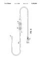
- FIG. 4 is a side view of the FIGS. 1 and 2 ultrasonic probe assembly with the ultrasonic transducer positioned to scan in a plane different from its scan plane in FIGS. 1 and 2.
- FIG. 5 is an end view of the FIGS. 1 and 2 ultrasonic probe assembly with the ultrasonic transducer positioned to scan as illustrated in FIG. 4.
- FIG. 6 is a plan view of an endoscope in which the ultrasonic probe assembly of FIGS. 1 through 5 can be incorporated.
- FIGS. 7A and 7B are sectional views which illustrate in more detail and on a larger scale the flexible connections between the two housings of the ultrasonic probe assembly of FIGS. 1 through 5 incorporated in the endoscope of FIG. 6.
- an ultrasonic probe assembly constructed in accordance with the present invention, includes a first housing 10, a ultrasonic transducer 12 and first mounting means for mounting transducer 12 for scanning movement of transducer 12 about a first axis.
- Ultrasonic transducer 12 can be of conventional construction and operation such as a 3.5-5 MHz transducer supplied by Echo Ultrasound and used typically for cardiac imaging.
- Ultrasonic transducer 12 is attached to a leg 14 and is mounted, for the embodiment of the present invention being described, by a pivot shaft 16 on which leg 14 is mounted and which defines an axis for scanning movement of ultrasonic transducer 12.
- FIG. 3 shows by dashed lines 12a and 12b the range of oscillatory scanning motion of ultrasonic transducer 12.
- a double-ended arrow 17 defines this range of motion which typically is 100 degrees.
- the first mounting means and ultrasonic transducer 12 are mounted to housing 10 for pivotal movement of the first mounting means about a second axis which is perpendicular to the scan axis of transducer 12.
- second mounting means which, for the embodiment of the present invention being described, include a bracket 19 and a pivot shaft 20.
- An ultrasonic probe assembly constructed in accordance with the present invention, also includes a second housing 21 spaced from first housing 10 and a drive motor 22 mounted in housing 21 and having a motor housing 22a and an output driver shaft 22b.
- Drive motor 22 which can be a DC reciprocating motor, provides the drive for oscillatory scanning movement of ultrasonic transducer 12.
- Drive motor 22 is rotatably mounted in housing 21, so that it can pivot when the scan plane of ultrasonic transducer 12 is to be changed.
- selection means in the form of a knob 24, for setting a selected pivotal position of the first mounting means in housing 10.
- the position of knob 24 and, therefore, the position of motor 22 determine the scan plane of ultrasonic transducer 12.
- An ultrasonic probe assembly constructed in accordance with the present invention, further includes first coupling means extending between output driver shaft 22b of motor 22 and ultrasonic transducer 12 for imparting scanning movement to transducer 12 in response to oscillatory movement of output driver shaft 22b.
- the first coupling means include, for the embodiment of the present invention being described, a flexible connection 26, made up of two lengths, attached at a first end to a drive pulley 28 which is fixed to output driver shaft 22b of motor 22. Flexible connection 26 also is attached at a second end to a pulley 30 which is mounted on pivot shaft 20 for reciprocating movement. Each length of flexible connection 26 extends through a sleeve 27 the opposite ends of which are anchored in housings 10 and 21.
- first bevel gear 32 Integral with pulley 30 is a first bevel gear 32 which meshes with a second bevel gear 34 to which leg 14 is attached.
- the oscillatory drive provided by motor 22 is imparted to ultrasonic transducer 12 through drive pulley 28, flexible connection 26, pulley 30, bevel gears 32 and 34, and leg 14.
- the length of flexible connection 26 and the length of each sleeve permits positioning first housing 10 and ultrasonic transducer 12 within a body cavity of a patient while second housing 21 with motor 22 remains outside the body of the patient.
- An ultrasonic probe assembly constructed in accordance with the present invention, further includes second coupling means extending between the scan-plane selection means at housing 21 and the second mounting means at housing 10 for positioning the first mounting means at housing 10 in response to movement of the selection means.
- the second coupling means include, for the embodiment of the present invention being described, a pulley 36 fixed to motor housing 22a and a second flexible connection 38 fixed at one end to pulley 36 and at a second end to a pulley 40 which is integral with bracket 19.
- knob 24 is turned, as represented by the double-ended arrow 41, this movement is imparted to bracket 19 through motor housing 22a, pulley 36, flexible connection 38 and pulley 40 to change the scan plane of ultrasonic transducer 12.
- the range of scan-plane variation can be up to one hundred eighty degrees.
- the length of flexible connection 38 is substantially coextensive with flexible connection 26, so that knob 24 with housing 21 is outside the body of the patient while housing 10 and ultrasonic transducer 12 are within a body cavity of the patient.
- flexible connections 26 and 38 extend through a flexible tube 42, the ends of which are attached by suitable means to housings 10 and 21.
- wires (not shown) which power ultrasonic transducer 12 and conduct imaging signals from transducer 12 extend through flexible tube 42.
- FIG. 6 illustrates the ultrasonic probe assembly of FIGS. 1 through 5 incorporated in an endoscope.
- Housings 10 and 21 are connected by flexible tube 42 through which flexible connections 26 and 38 extend.
- Knob 24 on housing 21 functions, as previously described, to change the scan plane of the ultrasonic transducer in housing 10.
- the drive motor (not shown in FIG. 6) is located in housing 21.
- a second knob 44 on housing 21 controls bending of the end of the flexible endoscope upward, downward and sideways to permit the end of the endoscope to make turns as it is passed through the body to the body cavity at which imaging is to take place.
- the wires (not shown) which power the ultrasonic transducer (not shown in FIG. 6) and conduct imaging signals from the transducer extend to a connector 46 which is adapted for connection into suitable signal processing and imaging equipment.
- flexible connection 26 from the FIGS. 1 through 5 ultrasonic probe assembly can include a multi-strand steel cable section 50 which is pinned to pulley 30. As the two lengths of multi-strand steel cable section 50 to either side of pulley 30 are pulled or pushed in response to the reciprocating movement of output driver shaft 22b of motor 22, pulley 30 turns.
- Flexible connection 26 also includes a single-strand steel music wire section 52 which is butt-welded to multi-strand steel cable section 50. At its opposite end, single-strand steel music wire section 52 is soldered to a steel surgical tubing section 54.
- Steel surgical tubing section 54 is soldered to an endless belt 56 which extends between pulley 28 and an idler pulley 58.
- endless belt 56 pinned to pulley 28 and pulley 28 fixed to output driver shaft 22b of motor 22, as output driver shaft 22b reciprocates, pulley 28 is driven and also reciprocates to cause endless belt 56 to undergo movements in opposite directions.
- Multi-strand steel cable section 50 is sufficiently flexible to conform to the tight radii in housing 10.
- Single-strand steel music wire section 52 provides sufficient stiffness and rigidity so that it can be pushed in push/pull operation.
- Steel surgical tubing section 54 serves as the inside wiper for the seal at the transition from wet to dry in an endoscope.
- Endless belt 56 in conjunction with idler pulley 58, besides converting the rotary motion of output driver shaft 22b of motor 22 to linear motion, adds stiffness and rigidity to effect push/pull motion.
- Flexible connection 38 by which the scan plane of ultrasonic transducer 12 is changed, can be arranged similar to flexible connection 26 just described.
Abstract
An ultrasonic probe assembly in which an ultrasonic transducer is mechanically scanned in response to a drive motor which is located in a housing spaced from the transducer such that the transducer can be positioned in a body cavity of patient while the housing containing the drive motor remains outside the body of the patient.
Description
The present invention relates, in general, to ultrasonic imaging and, in particular, to an ultrasonic probe assembly with the ultrasonic transducer arranged for insertion into a body cavity.
Ultrasonic probe assemblies having the ultrasonic transducer arranged for insertion into a body cavity (i.e. prostate probes, esophageal probes, vaginal probes) are in widespread use. Typically, the ultrasonic transducer, the transducer mount mechanism and the motor which imparts scanning movement to the ultrasonic transducer are housed at one end of an endoscope. Power to the motor and electrical signals, from which the image is developed, are conducted along wires extending through the endoscope. In addition, for those ultrasonic probe assemblies arranged for multi-plane scanning, the cables by which the scan plane of the ultrasonic transducer is changed mechanically extend through the endoscope to the transducer mount mechanism from a control remote from the transducer mount mechanism.
It is apparent that the sizes of the ultrasonic transducer, the transducer mount mechanism and the scanning motor dictate the size of the housing inserted into the body cavity Often, the size of this housing is too large for the desired applications of the ultrasonic probe assembly.
An ultrasonic probe assembly, constructed in accordance with the present invention, includes a first housing, a ultrasonic transducer and mounting means for mounting the ultrasonic transducer to the first housing for scanning movement of the ultrasonic transducer. Also included in this ultrasonic probe assembly are a second housing spaced from the first housing, a drive motor mounted in the second housing and having an output driver, and coupling means, including flexible connecting means, extending between the output driver of the motor and the ultrasonic transducer for imparting scanning movement to the ultrasonic transducer in response to the output driver. The flexible connecting means have a length which permits positioning the first housing with the ultrasonic transducer within a body cavity of a patient while the second housing remains outside the body of the patient.
When the present invention is incorporated in a multi-plane imaging ultrasonic probe assembly, the assembly also includes second mounting means for mounting the first mounting means and the ultrasonic transducer to the first housing for pivotal movement of the first mounting means about an axis perpendicular to the axis about which the ultrasonic transducer is scanned. Also included are selection means attached to the second housing containing the drive motor for setting a selected pivotal position of the first mounting means and second coupling means, including second flexible connecting means, extending between the selection means and the second mounting means for positioning the first mounting means in response to the selection means. The second flexible connecting means have a length substantially coextensive with the first flexible connecting means.
FIG. 1 is a top view of one preferred embodiment of an ultrasonic probe assembly constructed in accordance with the present invention.
FIG. 2 is a side view of the FIG. 1 ultrasonic probe assembly.
FIG. 3 is an end view of the FIGS. 1 and 2 ultrasonic probe assembly.
FIG. 4 is a side view of the FIGS. 1 and 2 ultrasonic probe assembly with the ultrasonic transducer positioned to scan in a plane different from its scan plane in FIGS. 1 and 2.
FIG. 5 is an end view of the FIGS. 1 and 2 ultrasonic probe assembly with the ultrasonic transducer positioned to scan as illustrated in FIG. 4.
FIG. 6 is a plan view of an endoscope in which the ultrasonic probe assembly of FIGS. 1 through 5 can be incorporated.
FIGS. 7A and 7B are sectional views which illustrate in more detail and on a larger scale the flexible connections between the two housings of the ultrasonic probe assembly of FIGS. 1 through 5 incorporated in the endoscope of FIG. 6.
Referring to FIGS. 1 through 5, an ultrasonic probe assembly, constructed in accordance with the present invention, includes a first housing 10, a ultrasonic transducer 12 and first mounting means for mounting transducer 12 for scanning movement of transducer 12 about a first axis. Ultrasonic transducer 12 can be of conventional construction and operation such as a 3.5-5 MHz transducer supplied by Echo Ultrasound and used typically for cardiac imaging. Ultrasonic transducer 12 is attached to a leg 14 and is mounted, for the embodiment of the present invention being described, by a pivot shaft 16 on which leg 14 is mounted and which defines an axis for scanning movement of ultrasonic transducer 12. FIG. 3 shows by dashed lines 12a and 12b the range of oscillatory scanning motion of ultrasonic transducer 12. A double-ended arrow 17 defines this range of motion which typically is 100 degrees.
The first mounting means and ultrasonic transducer 12 are mounted to housing 10 for pivotal movement of the first mounting means about a second axis which is perpendicular to the scan axis of transducer 12. This is accomplished by second mounting means which, for the embodiment of the present invention being described, include a bracket 19 and a pivot shaft 20. By this arrangement the plane of scanning of ultrasonic transducer 12 can be changed so that the body part, such as the heart, which is being imaged can be viewed in different ways (i.e. in longitudinal and transverse sections or any section in between). FIGS. 4 and 5 show ultrasonic transducer 12 positioned to scan in a plane different from the scan plane position of ultrasonic transducer 12 in FIGS. 1, 2 and 3.
An ultrasonic probe assembly, constructed in accordance with the present invention, also includes a second housing 21 spaced from first housing 10 and a drive motor 22 mounted in housing 21 and having a motor housing 22a and an output driver shaft 22b. Drive motor 22, which can be a DC reciprocating motor, provides the drive for oscillatory scanning movement of ultrasonic transducer 12. Drive motor 22 is rotatably mounted in housing 21, so that it can pivot when the scan plane of ultrasonic transducer 12 is to be changed.
Attached to motor housing 22a are selection means, in the form of a knob 24, for setting a selected pivotal position of the first mounting means in housing 10. The position of knob 24 and, therefore, the position of motor 22 determine the scan plane of ultrasonic transducer 12.
An ultrasonic probe assembly, constructed in accordance with the present invention, further includes first coupling means extending between output driver shaft 22b of motor 22 and ultrasonic transducer 12 for imparting scanning movement to transducer 12 in response to oscillatory movement of output driver shaft 22b. The first coupling means include, for the embodiment of the present invention being described, a flexible connection 26, made up of two lengths, attached at a first end to a drive pulley 28 which is fixed to output driver shaft 22b of motor 22. Flexible connection 26 also is attached at a second end to a pulley 30 which is mounted on pivot shaft 20 for reciprocating movement. Each length of flexible connection 26 extends through a sleeve 27 the opposite ends of which are anchored in housings 10 and 21. Integral with pulley 30 is a first bevel gear 32 which meshes with a second bevel gear 34 to which leg 14 is attached. As a result, the oscillatory drive provided by motor 22 is imparted to ultrasonic transducer 12 through drive pulley 28, flexible connection 26, pulley 30, bevel gears 32 and 34, and leg 14. The length of flexible connection 26 and the length of each sleeve permits positioning first housing 10 and ultrasonic transducer 12 within a body cavity of a patient while second housing 21 with motor 22 remains outside the body of the patient.
An ultrasonic probe assembly, constructed in accordance with the present invention, further includes second coupling means extending between the scan-plane selection means at housing 21 and the second mounting means at housing 10 for positioning the first mounting means at housing 10 in response to movement of the selection means. The second coupling means include, for the embodiment of the present invention being described, a pulley 36 fixed to motor housing 22a and a second flexible connection 38 fixed at one end to pulley 36 and at a second end to a pulley 40 which is integral with bracket 19. As a result, as knob 24 is turned, as represented by the double-ended arrow 41, this movement is imparted to bracket 19 through motor housing 22a, pulley 36, flexible connection 38 and pulley 40 to change the scan plane of ultrasonic transducer 12. The range of scan-plane variation can be up to one hundred eighty degrees. The length of flexible connection 38 is substantially coextensive with flexible connection 26, so that knob 24 with housing 21 is outside the body of the patient while housing 10 and ultrasonic transducer 12 are within a body cavity of the patient.
Preferably, flexible connections 26 and 38 extend through a flexible tube 42, the ends of which are attached by suitable means to housings 10 and 21. In addition, wires (not shown) which power ultrasonic transducer 12 and conduct imaging signals from transducer 12 extend through flexible tube 42.
FIG. 6 illustrates the ultrasonic probe assembly of FIGS. 1 through 5 incorporated in an endoscope. Housings 10 and 21 are connected by flexible tube 42 through which flexible connections 26 and 38 extend. Knob 24 on housing 21 functions, as previously described, to change the scan plane of the ultrasonic transducer in housing 10. The drive motor (not shown in FIG. 6) is located in housing 21. A second knob 44 on housing 21 controls bending of the end of the flexible endoscope upward, downward and sideways to permit the end of the endoscope to make turns as it is passed through the body to the body cavity at which imaging is to take place. The wires (not shown) which power the ultrasonic transducer (not shown in FIG. 6) and conduct imaging signals from the transducer extend to a connector 46 which is adapted for connection into suitable signal processing and imaging equipment.
Referring to FIGS. 7A and 7B, which should be viewed with the right-hand end of FIG. 7A leading to the left-hand end of FIG. 7B, flexible connection 26 from the FIGS. 1 through 5 ultrasonic probe assembly can include a multi-strand steel cable section 50 which is pinned to pulley 30. As the two lengths of multi-strand steel cable section 50 to either side of pulley 30 are pulled or pushed in response to the reciprocating movement of output driver shaft 22b of motor 22, pulley 30 turns.
Steel surgical tubing section 54 is soldered to an endless belt 56 which extends between pulley 28 and an idler pulley 58. With endless belt 56 pinned to pulley 28 and pulley 28 fixed to output driver shaft 22b of motor 22, as output driver shaft 22b reciprocates, pulley 28 is driven and also reciprocates to cause endless belt 56 to undergo movements in opposite directions.
The arrangement of flexible connection 26 which has just been described results in a connection having reduced hysteresis and backlash. Multi-strand steel cable section 50 is sufficiently flexible to conform to the tight radii in housing 10. Single-strand steel music wire section 52 provides sufficient stiffness and rigidity so that it can be pushed in push/pull operation. Steel surgical tubing section 54 serves as the inside wiper for the seal at the transition from wet to dry in an endoscope. Endless belt 56, in conjunction with idler pulley 58, besides converting the rotary motion of output driver shaft 22b of motor 22 to linear motion, adds stiffness and rigidity to effect push/pull motion.
The foregoing has set forth an exemplary and preferred embodiment of the present invention. It will be understood, however, that various other alternative embodiments will occur to those of ordinary skill in the art without departure from the spirit and scope of the present invention.
Claims (15)
1. An ultrasonic probe assembly comprising:
a first housing;
an ultrasonic transducer;
first mounting means for mounting said ultrasonic transducer for scanning movement of said transducer in a selected scan plane about a first axis;
second mounting means for mounting said first mounting means and sail ultrasonic transducer to said first housing for pivotal movement of said first mounting means with respect to said first housing about a second axis which is perpendicular to said first axis;
a second housing spaced from said first housing;
a drive motor rotatably mounted in said second housing and having a motor housing and an output driver;
selection means attached to said motor housing for setting a selected pivotal position of said first mounting means corresponding to said selected scan plane;
first coupling means, including first flexible connecting means, extending between said output driver of said drive motor and said ultrasonic transducer for imparting scanning movement to said transducer in response to movement of said output driver, said first flexible connecting means having a length which permits positioning said first housing and said transducer within a body cavity of a patient while said second housing remains outside the body of the patent;
and second coupling means, including second flexible connecting means, extending between said selection means and said second mounting means for positioning said first mounting means in response to movement of said selection means, said second flexible connecting means having a length substantially coextensive with said first flexible connecting means.
2. An ultrasonic probe assembly according to claim 1 wherein said drive motor is a reciprocating motor and said scanning movement of said ultrasonic transducer is oscillatory.
3. An ultrasonic probe assembly according to claim 2 further including a flexible tube extending between said first housing and said second housing and through which said first flexible connecting means and said second flexible connecting means extend.
4. A ultrasonic probe assembly according to claim 2 wherein the range of scanning movement of said ultrasonic transducer is 100 degrees.
5. An ultrasonic probe assembly according to claim 4 wherein the range of scan-plane variation of said ultrasonic transducer is one hundred eighty degrees.
6. An endoscope comprising:
a first housing;
an ultrasonic transducer for developing signals representative of a body part being imaged;
first mounting means for mounting said ultrasonic transducer for scanning movement of said transducer in a selected scan plane about a first axis;
second mounting means for mounting said first mounting means and said ultrasonic transducer to said first housing for pivotal movement of said first mounting means with respect to said first housing about a second axis which is perpendicular to said first axis;
a second housing spaced from said first housing;
a drive motor rotatably mounted in said second housing and having a motor housing and an output driver;
selection means attached to said motor housing for setting a selected pivotal position of said first mounting means corresponding to said selected scan plane;
first coupling means, including first flexible connecting means, extending between said output driver of said drive motor and said ultrasonic transducer for imparting scanning movement to said transducer in response to movement of said output driver, said first flexible connecting means having a length which permits positioning said first housing and said transducer within a body cavity of a patient to image a body part while said second housing remains outside the body of the patient;
second coupling means, including second flexible connecting means, extending between said selection means and said second mounting means for positioning said first mounting means in response to movement of said selection means, said second flexible connecting means having a length substantially coextensive with said first flexible connection means;
a flexible tube extending between said first housing and said second housing and through which said first flexible connecting means and said second flexible connecting means extend;
and means for conducting said signals developed by said ultrasonic transducer to signal processing and imaging equipment.
7. An ultrasonic probe assembly comprising:
a first housing;
an ultrasonic transducer;
mounting means for mounting said ultrasonic transducer to said first housing for scanning movement of said transducer;
a second housing spaced from said first housing;
a drive motor rotatably mounted in said second housing and having an output driver;
and coupling means, including flexible connecting means, extending between said output driver of said drive motor and said ultrasonic transducer for imparting scanning movement to said transducer in response to movement of said output driver, said flexible connecting means:
(a) including:
(i) a multi-strand steel cable section coupled to said ultrasonic transducer,
(ii) a single-strand steel music wire section attached to said multi-strand steel cable section,
(iii) a steel surgical tubing section attached to said single-strand steel music wire section,
(iv) an idler pulley, and
(v) an endless belt to which said steel surgical tubing section is attached and which extends between said idler pulley and said output driver of said driver motor, and
(b) having a length which permits positioning said first housing and said transducer within a body cavity of a patient while said second housing remains outside the body of the patient.
8. A ultrasonic probe assembly according to claim 7 wherein said coupling means further include:
(a) a first pulley in said second housing fixed to said output driver of said drive motor and to which a first end of said flexible connecting means is attached,
(b) a second pulley in said first housing and to which a second end of said flexible connecting means is attached,
(c) a first bevel gear in said first housing and integral with said second pulley, and
(d) a second bevel gear in said first housing, meshing with said first bevel gear and connected to said ultrasonic transducer.
9. An ultrasonic probe assembly according to claim 7 wherein said coupling means further include:
(a) a first pulley in said second housing fixed to said output driver of said drive motor and to which said endless belt is attached,
(b) a second pulley in said first housing and to which said multi-strand steel cable section is attached,
(c) a first bevel gear in said first housing and integral with said second pulley, and
(d) a second bevel gear in said first housing, meshing with said first bevel gear and connected to said ultrasonic transducer.
10. An ultrasonic probe assembly comprising:
a first housing;
an ultrasonic transducer;
first mounting means for mounting said ultrasonic transducer for oscillatory scanning movement of said transducer about a first axis;
second mounting means for mounting said first mounting means and said ultrasonic transducer to said first housing for pivotal movement of said first mounting means about a second axis which is perpendicular to said first axis;
a second housing spaced from said first housing;
a reciprocating drive motor rotatably mounted in said second housing and having a motor housing and an output driver;
selection means attached to said motor housing for setting a selected pivotal position of said first mounting means;
first coupling means, including first flexible connecting means, extending between said output driver of said drive motor and said ultrasonic transducer for imparting scanning movement to said transducer in response to movement of said output driver, said first flexible connecting means having a length which permits positioning said first housing and said transducer within a body cavity of a patient while said second housing remains outside the body of the patient and including:
(1) a first multi-strand steel cable section coupled to said ultrasonic transducer,
(2) a first single-strand steel music wire section attached to said multi-strand steel cable section,
(3) a first steel surgical tubing section attached to said single-strand steel music wire section,
(4) a first idler pulley, and
(5) a first endless belt to which said first steel surgical tubing section is attached and which extends between said first idler pulley and said output driver of said driver motor;
and second coupling means, including second flexible connecting means, extending between said selection means and said second mounting means for positioning said first mounting means in response to movement of said selection means, said second flexible connecting means having a length substantially coextensive with said first flexible connecting means and including:
(1) a second multi-strand steel cable section coupled to said second mounting means,
(2) a second single-strand steel music wire section attached to said second multi-strand steel cable section,
(3) a second steel surgical tubing section attached to said second single-strand steel music wire section,
(4) a second idler pulley, and
(5) a second endless belt to which said second steel surgical tubing section is attached and which extends between said idler pulley and said selection means.
11. An ultrasonic probe assembly according to claim 10 wherein:
(a) said first coupling means include:
(1) a first pulley in said second housing fixed to said output driver of said drive motor and to which said first endless belt is attached,
(2) a second pulley in said first housing and to which said first multi-strand steel cable section is attached,
(3) a first bevel gear in said first housing and integral with said second pulley, and
(4) a second bevel gear in said first housing, meshing with said first bevel gear and connected to said ultrasonic transducer, and
(b) said second coupling means include:
(1) a third pulley in said second housing fixed to said selection means and to which said second endless belt is attached, and
(2) a fourth pulley in said first housing attached to said second mounting means and to which said second multi-strand steel cable section is attached.
12. An ultrasonic probe assembly according to claim 11 wherein said selection means include a rotatable knob fixed to said housing of said drive motor.
13. An ultrasonic probe assembly comprising:
a first housing;
an ultrasonic transducer;
first mounting means for mounting said ultrasonic transducer for oscillatory scanning movement of said transducer about a first axis;
second mounting means for mounting said first mounting means and said ultrasonic transducer to said first housing for pivotal movement of said first mounting means about a second axis which is perpendicular to said first axis;
a second housing spaced from said first housing;
a reciprocating drive motor rotatably mounted in said second housing and having a motor housing and an output driver;
a selection means attached to said motor housing for setting a selected pivotal position of said first mounting means;
first coupling means, including:
(1) first flexible connecting means, extending between said output driver of said drive motor and said ultrasonic transducer for imparting scanning movement to said transducer in response to movement of said output driver, said first flexible connecting means having a length which permits positioning said first housing and said transducer within a body cavity of a patient while said second housing remains outside the body of the patient,
(2) a first pulley in said second housing fixed to said output driver of said drive motor and to which a first end of said flexible connecting means is attached,
(3) a second pulley in said first housing and to which a second end of said flexible connecting means is attached,
(4) a first bevel gear in said first housing and integral with said second pulley, and
(5) a second bevel gear in said first housing, meshing with said first bevel gear and connected to said ultrasonic transducer;
a second coupling means, including:
(1) second flexible connecting means, extending between said selection means and said second mounting means for positioning said first mounting means in response to movement of said selection means, said second flexible connecting means having a length substantially coextensive with said first flexible connecting means,
(2) a third pulley in said second housing fixed to said selection means and to which a first end of said second flexible connecting means is attached, and
(3) a fourth pulley in said first housing attached to said second mounting means and to which a second end of said second flexible connecting means is attached.
14. An ultrasonic probe assembly comprising:
a first housing;
an ultrasonic transducer;
first mounting means for mounting said ultrasonic transducer for scanning movement of said transducer about a first axis;
second mounting means for mounting said first mounting means and said ultrasonic transducer to said first housing for pivotal movement of said first mounting means about a second axis which is perpendicular to said first axis;
a second housing spaced from said first housing;
a drive motor rotatably mounted in said second housing and having a motor and an output driver;
selection means attached to said motor housing for setting a selected pivotal position of said first mounting means;
first coupling means, including first flexible connecting means, extending between said output driver of said drive motor and said ultrasonic transducer for imparting scanning movement to said transducer in response to movement of said output driver, said first flexible connecting means having a length which permits positioning said first housing and said transducer within a body cavity of a patient while said second housing remains outside the body of the patient and including:
(1) first and second flexible connection lengths coupling said output driver of said motor to said transducer, and
(2) first and second sleeves through which said first and said second flexible connection lengths of said first flexible connecting means, respectively, extend and having a length substantially coextensive with said first and said second flexible connection lengths of said first flexible connecting means;
and second coupling means, including second flexible connecting means, extending between said selection means and said second mounting means for positioning said first mounting means in response to movement of said selection means, said second flexible connecting means having a length substantially coextensive with said first flexible connecting means and including:
(1) first and second flexible connection lengths coupling said selection means to said second mounting means, and
(2) first and second sleeves through which said first and said second flexible connection lengths of said second flexible connecting means, respectively, extend and having a length substantially coextensive with said first and said second flexible connection lengths of said second flexible connecting means.
15. An ultrasonic probe assembly according to claim 14 wherein opposite ends of said first and said second sleeves of said first flexible connecting means and opposite ends of said first and said second sleeves of said second flexible connecting means are anchored in said first and said second housings.
Priority Applications (7)
| Application Number | Priority Date | Filing Date | Title |
|---|---|---|---|
| US07/782,678 US5255684A (en) | 1991-10-25 | 1991-10-25 | Ultrasonic probe assembly |
| CA002121907A CA2121907A1 (en) | 1991-10-25 | 1992-10-19 | Ultrasonic probe assembly |
| JP50785793A JP3276008B2 (en) | 1991-10-25 | 1992-10-19 | Ultrasonic probe assembly |
| PCT/US1992/008909 WO1993007808A1 (en) | 1991-10-25 | 1992-10-19 | Ultrasonic probe assembly |
| DE69222058T DE69222058T2 (en) | 1991-10-25 | 1992-10-19 | ULTRA SOUND PROBE MOUNTING |
| KR1019940701366A KR100234889B1 (en) | 1991-10-25 | 1992-10-19 | Ultrasonic probe assembly |
| EP92922178A EP0615426B1 (en) | 1991-10-25 | 1992-10-19 | Ultrasonic probe assembly |
Applications Claiming Priority (1)
| Application Number | Priority Date | Filing Date | Title |
|---|---|---|---|
| US07/782,678 US5255684A (en) | 1991-10-25 | 1991-10-25 | Ultrasonic probe assembly |
Publications (1)
| Publication Number | Publication Date |
|---|---|
| US5255684A true US5255684A (en) | 1993-10-26 |
Family
ID=25126837
Family Applications (1)
| Application Number | Title | Priority Date | Filing Date |
|---|---|---|---|
| US07/782,678 Expired - Fee Related US5255684A (en) | 1991-10-25 | 1991-10-25 | Ultrasonic probe assembly |
Country Status (7)
| Country | Link |
|---|---|
| US (1) | US5255684A (en) |
| EP (1) | EP0615426B1 (en) |
| JP (1) | JP3276008B2 (en) |
| KR (1) | KR100234889B1 (en) |
| CA (1) | CA2121907A1 (en) |
| DE (1) | DE69222058T2 (en) |
| WO (1) | WO1993007808A1 (en) |
Cited By (21)
| Publication number | Priority date | Publication date | Assignee | Title |
|---|---|---|---|---|
| US5413107A (en) * | 1994-02-16 | 1995-05-09 | Tetrad Corporation | Ultrasonic probe having articulated structure and rotatable transducer head |
| US5423319A (en) * | 1994-06-15 | 1995-06-13 | Hewlett-Packard Company | Integrated impedance matching layer to acoustic boundary problems for clinical ultrasonic transducers |
| US5450851A (en) * | 1994-05-25 | 1995-09-19 | Advanced Technology Laboratories, Inc. | Ultrasonic probe assembly |
| US5630416A (en) * | 1994-09-19 | 1997-05-20 | Fujitsu, Ltd. | Ultrasonic diagnostic probe |
| US5662116A (en) * | 1995-09-12 | 1997-09-02 | Fuji Photo Optical Co., Ltd. | Multi-plane electronic scan ultrasound probe |
| US5666970A (en) * | 1995-05-02 | 1997-09-16 | Heart Rhythm Technologies, Inc. | Locking mechanism for catheters |
| US5681280A (en) * | 1995-05-02 | 1997-10-28 | Heart Rhythm Technologies, Inc. | Catheter control system |
| US5741320A (en) * | 1995-05-02 | 1998-04-21 | Heart Rhythm Technologies, Inc. | Catheter control system having a pulley |
| US5740804A (en) * | 1996-10-18 | 1998-04-21 | Esaote, S.P.A | Multipanoramic ultrasonic probe |
| US5779639A (en) * | 1996-11-21 | 1998-07-14 | Hewlett-Packard Company | Ultrasound probe with offset angle tip |
| US6690963B2 (en) | 1995-01-24 | 2004-02-10 | Biosense, Inc. | System for determining the location and orientation of an invasive medical instrument |
| EP1576926A1 (en) * | 2002-12-24 | 2005-09-21 | Matsushita Electric Industrial Co., Ltd. | Ultrasonic probe |
| US20060247528A1 (en) * | 2003-05-19 | 2006-11-02 | Matsushita Electric Industrial Co., Ltd. | Ultrasonic probe |
| CN1307945C (en) * | 2004-06-28 | 2007-04-04 | 天津大学 | Medical mini supersonic probe via endoscope |
| CN1322839C (en) * | 2004-06-28 | 2007-06-27 | 天津大学 | Medical mini supersonic -OCT probe via endoscope |
| US20080236311A1 (en) * | 2007-04-02 | 2008-10-02 | Naoki Kanayama | Concentric double axis mechanism having bevel gears |
| US20100174189A1 (en) * | 2007-10-12 | 2010-07-08 | Innoscion, Llc | Remotely controlled implantable transducer and associated displays and controls |
| US20120123269A1 (en) * | 2009-07-24 | 2012-05-17 | Alpinion Medical Systems Co., Ltd. | Three-dimensional ultrasonic scanner |
| US8371173B1 (en) * | 2009-03-10 | 2013-02-12 | Sandia Corporation | Ultrasonic probe deployment device for increased wave transmission and rapid area scan inspections |
| WO2014201888A1 (en) * | 2013-06-19 | 2014-12-24 | 深圳迈瑞生物医疗电子股份有限公司 | 3d mechanical probe and cable transmission device |
| US20220304549A1 (en) * | 2021-03-25 | 2022-09-29 | Endoscopy Development Company, LLC | Endoscope |
Families Citing this family (4)
| Publication number | Priority date | Publication date | Assignee | Title |
|---|---|---|---|---|
| CN1226960C (en) * | 1994-08-19 | 2005-11-16 | 生物感觉有限公司 | Medical diagnosis, treatment and imaging systems |
| KR100741694B1 (en) * | 2004-12-29 | 2007-07-27 | 주식회사 메디슨 | Device for pivoting ultrasound element of probe in ultrasonic diagnosis apparatus |
| KR101632336B1 (en) * | 2014-07-25 | 2016-06-21 | 주식회사 케이비에이치한국생활건강 | Inserting apparatus for diagnosing and curing prostate diseases |
| KR101589273B1 (en) * | 2014-07-25 | 2016-01-28 | 넥서스메디케어 주식회사 | Prostate diseases diagnosing method using inserting aparatus for curing prostate diseases |
Citations (27)
| Publication number | Priority date | Publication date | Assignee | Title |
|---|---|---|---|---|
| US4014207A (en) * | 1970-08-07 | 1977-03-29 | Picker Electronics, Inc. | Sector scanning ultrasonic inspection apparatus |
| US4149419A (en) * | 1977-11-25 | 1979-04-17 | Smith Kline Instruments, Inc. | Ultrasonic transducer probe |
| US4269066A (en) * | 1979-08-16 | 1981-05-26 | Fischer Christopher L | Ultrasonic sensing apparatus |
| US4272991A (en) * | 1979-02-09 | 1981-06-16 | Litton Industrial Products, Inc. | Scanning method and apparatus |
| US4330874A (en) * | 1980-08-15 | 1982-05-18 | Technicare Corporation | Mechanical sector scanner head and power train |
| US4362058A (en) * | 1980-10-24 | 1982-12-07 | New York University | Ultrasonic diagnostic apparatus |
| US4374525A (en) * | 1980-04-28 | 1983-02-22 | Olympus Optical Co., Ltd. | Ultrasonic diagnostic apparatus for endoscope |
| US4375818A (en) * | 1979-03-12 | 1983-03-08 | Olympus Optical Company Ltd. | Ultrasonic diagnosis system assembled into endoscope |
| EP0079525A1 (en) * | 1981-11-04 | 1983-05-25 | Olympus Optical Co., Ltd. | Endoscope apparatus with electric deflection mechanism |
| US4385521A (en) * | 1979-10-16 | 1983-05-31 | Siemens Aktiengesellschaft | Ultrasonic apparatus for sector scanning |
| US4494548A (en) * | 1982-04-20 | 1985-01-22 | Biosound, Inc. | Ultrasonic sector scanner |
| US4543960A (en) * | 1983-04-11 | 1985-10-01 | Advanced Technology Laboratories, Inc. | Transesophageal echo cardiography scanhead |
| US4567895A (en) * | 1984-04-02 | 1986-02-04 | Advanced Technology Laboratories, Inc. | Fully wetted mechanical ultrasound scanhead |
| US4637256A (en) * | 1983-06-23 | 1987-01-20 | Matsushita Electric Industrial Co., Ltd. | Ultrasonic probe having dual-motion transducer |
| US4732156A (en) * | 1985-06-21 | 1988-03-22 | Olympus Optical Co., Ltd. | Ultrasonic endoscope |
| US4756313A (en) * | 1986-11-05 | 1988-07-12 | Advanced Diagnostic Medical Systems, Inc. | Ultrasonic probe |
| US4757818A (en) * | 1986-03-03 | 1988-07-19 | Angelsen Bjorn A J | Ultrasonic transducer probe with linear motion drive mechanism |
| US4787247A (en) * | 1986-07-23 | 1988-11-29 | Sonomed Technology, Inc. | Scanning apparatus and method |
| US4807634A (en) * | 1986-02-04 | 1989-02-28 | Kabushiki Kaisha Toshiba | Mechanical type ultrasonic scanner |
| EP0317049A2 (en) * | 1987-11-13 | 1989-05-24 | Advanced Diagnostic Medical Systems, Inc. | Ultrasonic probe |
| US4841979A (en) * | 1988-01-25 | 1989-06-27 | Capistrano Labs, Inc. | Ultrasonic prostate probe assembly |
| US4850362A (en) * | 1987-06-02 | 1989-07-25 | Interspec, Inc. | Doppler peripheral vascular probe |
| US4913158A (en) * | 1986-01-30 | 1990-04-03 | Matsushita Electric Industrial Co., Ltd. | Ultrasonic probe for medical diagnostic examinations |
| US5048529A (en) * | 1988-09-01 | 1991-09-17 | Elscint Ltd. | Ultrasonic transducer probe |
| US5050610A (en) * | 1990-11-14 | 1991-09-24 | Advanced Technology Laboratories, Inc. | Transesophageal ultrasonic scanhead |
| US5090414A (en) * | 1988-08-22 | 1992-02-25 | Kabushiki Kaisha Toshiba | Intracavitary ultrasound probe |
| US5181514A (en) * | 1991-05-21 | 1993-01-26 | Hewlett-Packard Company | Transducer positioning system |
-
1991
- 1991-10-25 US US07/782,678 patent/US5255684A/en not_active Expired - Fee Related
-
1992
- 1992-10-19 CA CA002121907A patent/CA2121907A1/en not_active Abandoned
- 1992-10-19 WO PCT/US1992/008909 patent/WO1993007808A1/en active IP Right Grant
- 1992-10-19 DE DE69222058T patent/DE69222058T2/en not_active Expired - Fee Related
- 1992-10-19 EP EP92922178A patent/EP0615426B1/en not_active Expired - Lifetime
- 1992-10-19 JP JP50785793A patent/JP3276008B2/en not_active Expired - Fee Related
- 1992-10-19 KR KR1019940701366A patent/KR100234889B1/en not_active IP Right Cessation
Patent Citations (28)
| Publication number | Priority date | Publication date | Assignee | Title |
|---|---|---|---|---|
| US4014207A (en) * | 1970-08-07 | 1977-03-29 | Picker Electronics, Inc. | Sector scanning ultrasonic inspection apparatus |
| US4014207B1 (en) * | 1970-08-07 | 1986-08-12 | ||
| US4149419A (en) * | 1977-11-25 | 1979-04-17 | Smith Kline Instruments, Inc. | Ultrasonic transducer probe |
| US4272991A (en) * | 1979-02-09 | 1981-06-16 | Litton Industrial Products, Inc. | Scanning method and apparatus |
| US4375818A (en) * | 1979-03-12 | 1983-03-08 | Olympus Optical Company Ltd. | Ultrasonic diagnosis system assembled into endoscope |
| US4269066A (en) * | 1979-08-16 | 1981-05-26 | Fischer Christopher L | Ultrasonic sensing apparatus |
| US4385521A (en) * | 1979-10-16 | 1983-05-31 | Siemens Aktiengesellschaft | Ultrasonic apparatus for sector scanning |
| US4374525A (en) * | 1980-04-28 | 1983-02-22 | Olympus Optical Co., Ltd. | Ultrasonic diagnostic apparatus for endoscope |
| US4330874A (en) * | 1980-08-15 | 1982-05-18 | Technicare Corporation | Mechanical sector scanner head and power train |
| US4362058A (en) * | 1980-10-24 | 1982-12-07 | New York University | Ultrasonic diagnostic apparatus |
| EP0079525A1 (en) * | 1981-11-04 | 1983-05-25 | Olympus Optical Co., Ltd. | Endoscope apparatus with electric deflection mechanism |
| US4494548A (en) * | 1982-04-20 | 1985-01-22 | Biosound, Inc. | Ultrasonic sector scanner |
| US4543960A (en) * | 1983-04-11 | 1985-10-01 | Advanced Technology Laboratories, Inc. | Transesophageal echo cardiography scanhead |
| US4637256A (en) * | 1983-06-23 | 1987-01-20 | Matsushita Electric Industrial Co., Ltd. | Ultrasonic probe having dual-motion transducer |
| US4567895A (en) * | 1984-04-02 | 1986-02-04 | Advanced Technology Laboratories, Inc. | Fully wetted mechanical ultrasound scanhead |
| US4732156A (en) * | 1985-06-21 | 1988-03-22 | Olympus Optical Co., Ltd. | Ultrasonic endoscope |
| US4913158A (en) * | 1986-01-30 | 1990-04-03 | Matsushita Electric Industrial Co., Ltd. | Ultrasonic probe for medical diagnostic examinations |
| US4807634A (en) * | 1986-02-04 | 1989-02-28 | Kabushiki Kaisha Toshiba | Mechanical type ultrasonic scanner |
| US4757818A (en) * | 1986-03-03 | 1988-07-19 | Angelsen Bjorn A J | Ultrasonic transducer probe with linear motion drive mechanism |
| US4787247A (en) * | 1986-07-23 | 1988-11-29 | Sonomed Technology, Inc. | Scanning apparatus and method |
| US4756313A (en) * | 1986-11-05 | 1988-07-12 | Advanced Diagnostic Medical Systems, Inc. | Ultrasonic probe |
| US4850362A (en) * | 1987-06-02 | 1989-07-25 | Interspec, Inc. | Doppler peripheral vascular probe |
| EP0317049A2 (en) * | 1987-11-13 | 1989-05-24 | Advanced Diagnostic Medical Systems, Inc. | Ultrasonic probe |
| US4841979A (en) * | 1988-01-25 | 1989-06-27 | Capistrano Labs, Inc. | Ultrasonic prostate probe assembly |
| US5090414A (en) * | 1988-08-22 | 1992-02-25 | Kabushiki Kaisha Toshiba | Intracavitary ultrasound probe |
| US5048529A (en) * | 1988-09-01 | 1991-09-17 | Elscint Ltd. | Ultrasonic transducer probe |
| US5050610A (en) * | 1990-11-14 | 1991-09-24 | Advanced Technology Laboratories, Inc. | Transesophageal ultrasonic scanhead |
| US5181514A (en) * | 1991-05-21 | 1993-01-26 | Hewlett-Packard Company | Transducer positioning system |
Cited By (32)
| Publication number | Priority date | Publication date | Assignee | Title |
|---|---|---|---|---|
| US5413107A (en) * | 1994-02-16 | 1995-05-09 | Tetrad Corporation | Ultrasonic probe having articulated structure and rotatable transducer head |
| US5450851A (en) * | 1994-05-25 | 1995-09-19 | Advanced Technology Laboratories, Inc. | Ultrasonic probe assembly |
| US5423319A (en) * | 1994-06-15 | 1995-06-13 | Hewlett-Packard Company | Integrated impedance matching layer to acoustic boundary problems for clinical ultrasonic transducers |
| US5630416A (en) * | 1994-09-19 | 1997-05-20 | Fujitsu, Ltd. | Ultrasonic diagnostic probe |
| US6690963B2 (en) | 1995-01-24 | 2004-02-10 | Biosense, Inc. | System for determining the location and orientation of an invasive medical instrument |
| US5666970A (en) * | 1995-05-02 | 1997-09-16 | Heart Rhythm Technologies, Inc. | Locking mechanism for catheters |
| US5681280A (en) * | 1995-05-02 | 1997-10-28 | Heart Rhythm Technologies, Inc. | Catheter control system |
| US5741320A (en) * | 1995-05-02 | 1998-04-21 | Heart Rhythm Technologies, Inc. | Catheter control system having a pulley |
| US5662116A (en) * | 1995-09-12 | 1997-09-02 | Fuji Photo Optical Co., Ltd. | Multi-plane electronic scan ultrasound probe |
| US5740804A (en) * | 1996-10-18 | 1998-04-21 | Esaote, S.P.A | Multipanoramic ultrasonic probe |
| US5779639A (en) * | 1996-11-21 | 1998-07-14 | Hewlett-Packard Company | Ultrasound probe with offset angle tip |
| US6788967B2 (en) | 1997-05-14 | 2004-09-07 | Biosense, Inc. | Medical diagnosis, treatment and imaging systems |
| EP1576926A1 (en) * | 2002-12-24 | 2005-09-21 | Matsushita Electric Industrial Co., Ltd. | Ultrasonic probe |
| US20060074316A1 (en) * | 2002-12-24 | 2006-04-06 | Matsushita Electric Industrial Co., Ltd. | Ultrasonic probe |
| US8083681B2 (en) * | 2002-12-24 | 2011-12-27 | Panasonic Corporation | Ultrasonic probe |
| EP1576926A4 (en) * | 2002-12-24 | 2009-02-11 | Panasonic Corp | Ultrasonic probe |
| US20060247528A1 (en) * | 2003-05-19 | 2006-11-02 | Matsushita Electric Industrial Co., Ltd. | Ultrasonic probe |
| US8021304B2 (en) * | 2003-05-19 | 2011-09-20 | Panasonic Corporation | Ultrasonic probe |
| CN1322839C (en) * | 2004-06-28 | 2007-06-27 | 天津大学 | Medical mini supersonic -OCT probe via endoscope |
| CN1307945C (en) * | 2004-06-28 | 2007-04-04 | 天津大学 | Medical mini supersonic probe via endoscope |
| US7752938B2 (en) * | 2007-04-02 | 2010-07-13 | Harmonic Drive Systems Inc. | Concentric double axis mechanism having bevel gears |
| US20080236311A1 (en) * | 2007-04-02 | 2008-10-02 | Naoki Kanayama | Concentric double axis mechanism having bevel gears |
| US8235903B2 (en) * | 2007-10-12 | 2012-08-07 | Innoscion, Llc | Remotely controlled implantable transducer and associated displays and controls |
| US20100174189A1 (en) * | 2007-10-12 | 2010-07-08 | Innoscion, Llc | Remotely controlled implantable transducer and associated displays and controls |
| US8371173B1 (en) * | 2009-03-10 | 2013-02-12 | Sandia Corporation | Ultrasonic probe deployment device for increased wave transmission and rapid area scan inspections |
| US20120123269A1 (en) * | 2009-07-24 | 2012-05-17 | Alpinion Medical Systems Co., Ltd. | Three-dimensional ultrasonic scanner |
| US8777861B2 (en) * | 2009-07-24 | 2014-07-15 | Alpinion Medical Systems Co., Ltd. | Three-dimensional ultrasonic scanner |
| WO2014201888A1 (en) * | 2013-06-19 | 2014-12-24 | 深圳迈瑞生物医疗电子股份有限公司 | 3d mechanical probe and cable transmission device |
| CN104224228A (en) * | 2013-06-19 | 2014-12-24 | 深圳迈瑞生物医疗电子股份有限公司 | 3D (three-dimensional) mechanical probe and rope transmission device |
| US10398410B2 (en) | 2013-06-19 | 2019-09-03 | Shenzhen Mindray Bio-Medical Electronics Co., Ltd. | Tension transmission device and three-dimensional mechanical probe using same |
| US11179139B2 (en) * | 2013-06-19 | 2021-11-23 | Shenzhen Mindray Bio-Medical Electronics Co., Ltd. | Tension transmission device and three-dimensional mechanical probe using same |
| US20220304549A1 (en) * | 2021-03-25 | 2022-09-29 | Endoscopy Development Company, LLC | Endoscope |
Also Published As
| Publication number | Publication date |
|---|---|
| WO1993007808A1 (en) | 1993-04-29 |
| DE69222058D1 (en) | 1997-10-09 |
| KR100234889B1 (en) | 1999-12-15 |
| JPH07500269A (en) | 1995-01-12 |
| JP3276008B2 (en) | 2002-04-22 |
| EP0615426B1 (en) | 1997-09-03 |
| EP0615426A1 (en) | 1994-09-21 |
| DE69222058T2 (en) | 1998-01-02 |
| CA2121907A1 (en) | 1993-04-29 |
Similar Documents
| Publication | Publication Date | Title |
|---|---|---|
| US5255684A (en) | Ultrasonic probe assembly | |
| US5450851A (en) | Ultrasonic probe assembly | |
| US4543960A (en) | Transesophageal echo cardiography scanhead | |
| US4834102A (en) | Endoscope for transesophageal echocardiography | |
| US4977898A (en) | Miniaturized encapsulated ultrasonic transducer | |
| US5211176A (en) | Ultrasound examination system | |
| US5427103A (en) | MRI apparatus for receiving nuclear-magnetic resonance signals of a living body | |
| US5170793A (en) | Ultrasonic probe | |
| US4374525A (en) | Ultrasonic diagnostic apparatus for endoscope | |
| EP0065275B1 (en) | Ultrasonic diagnostic apparatus | |
| EP0460711B1 (en) | Ultrasonic probe | |
| JP2550778B2 (en) | Ultrasonic inspection equipment | |
| WO2000033741A3 (en) | Loop imaging catheter | |
| JP4652518B2 (en) | Ultrasound endoscope diagnosis device | |
| JPH07275243A (en) | Body insertion type ultrasonic diagnostic device | |
| US6063035A (en) | Coupling adaptor for endoscopically inserting ultrasound probe | |
| US5150715A (en) | Ultrasound-imaging diagnostic system | |
| CN115040055A (en) | Push-pull type endoscope handle | |
| JP3684156B2 (en) | Ultrasound endoscope | |
| JP4363956B2 (en) | Ultrasound endoscope | |
| JP2000217824A (en) | Ultrasonic endoscope | |
| JPH05309066A (en) | Endoscope device | |
| JP3130551B2 (en) | Ultrasonic diagnostic device in body cavity | |
| JP2712908B2 (en) | Radial scanning ultrasonic inspection system | |
| JP4674426B2 (en) | Ultrasonic probe |
Legal Events
| Date | Code | Title | Description |
|---|---|---|---|
| AS | Assignment |
Owner name: INTERSPEC, INC., PENNSYLVANIA Free format text: ASSIGNMENT OF ASSIGNORS INTEREST.;ASSIGNOR:RELLO, MICHAEL J.;REEL/FRAME:005938/0554 Effective date: 19911023 |
|
| CC | Certificate of correction | ||
| FPAY | Fee payment |
Year of fee payment: 4 |
|
| FPAY | Fee payment |
Year of fee payment: 8 |
|
| REMI | Maintenance fee reminder mailed | ||
| LAPS | Lapse for failure to pay maintenance fees | ||
| STCH | Information on status: patent discontinuation |
Free format text: PATENT EXPIRED DUE TO NONPAYMENT OF MAINTENANCE FEES UNDER 37 CFR 1.362 |
|
| FP | Lapsed due to failure to pay maintenance fee |
Effective date: 20051026 |