US5257614A - Gas powered gun - Google Patents
Gas powered gun Download PDFInfo
- Publication number
- US5257614A US5257614A US07/916,527 US91652792A US5257614A US 5257614 A US5257614 A US 5257614A US 91652792 A US91652792 A US 91652792A US 5257614 A US5257614 A US 5257614A
- Authority
- US
- United States
- Prior art keywords
- hammer
- bolt
- central bore
- barrel
- gas
- Prior art date
- Legal status (The legal status is an assumption and is not a legal conclusion. Google has not performed a legal analysis and makes no representation as to the accuracy of the status listed.)
- Expired - Lifetime
Links
Images


Classifications
-
- F—MECHANICAL ENGINEERING; LIGHTING; HEATING; WEAPONS; BLASTING
- F41—WEAPONS
- F41B—WEAPONS FOR PROJECTING MISSILES WITHOUT USE OF EXPLOSIVE OR COMBUSTIBLE PROPELLANT CHARGE; WEAPONS NOT OTHERWISE PROVIDED FOR
- F41B11/00—Compressed-gas guns, e.g. air guns; Steam guns
- F41B11/60—Compressed-gas guns, e.g. air guns; Steam guns characterised by the supply of compressed gas
- F41B11/62—Compressed-gas guns, e.g. air guns; Steam guns characterised by the supply of compressed gas with pressure supplied by a gas cartridge
-
- F—MECHANICAL ENGINEERING; LIGHTING; HEATING; WEAPONS; BLASTING
- F41—WEAPONS
- F41B—WEAPONS FOR PROJECTING MISSILES WITHOUT USE OF EXPLOSIVE OR COMBUSTIBLE PROPELLANT CHARGE; WEAPONS NOT OTHERWISE PROVIDED FOR
- F41B11/00—Compressed-gas guns, e.g. air guns; Steam guns
-
- F—MECHANICAL ENGINEERING; LIGHTING; HEATING; WEAPONS; BLASTING
- F41—WEAPONS
- F41B—WEAPONS FOR PROJECTING MISSILES WITHOUT USE OF EXPLOSIVE OR COMBUSTIBLE PROPELLANT CHARGE; WEAPONS NOT OTHERWISE PROVIDED FOR
- F41B11/00—Compressed-gas guns, e.g. air guns; Steam guns
- F41B11/70—Details not provided for in F41B11/50 or F41B11/60
- F41B11/72—Valves; Arrangement of valves
- F41B11/723—Valves; Arrangement of valves for controlling gas pressure for firing the projectile only
Definitions
- FIGS. 1A and 1B A very common style of paint gun presently in use is shown diagrametrically in FIGS. 1A and 1B.
- This prior art gun comprises (I) a handle; (II) a barrel attached to the handle, the barrel having a central bore with a forward end which is in communication with the exterior of the gun, a rearward end and a longitudinal axis; (III) a projectile repository attached to the barrel; (IV) a projectile chamber disposed within the central bore of the barrel and in communication with the forward end of the central bore of the barrel; (V) projectile insertion means for removing a projectile from the projectile repository and placing it into the projectile chamber; (VI) a bolt disposed within the central bore of the barrel rearward of the projectile chamber, the bolt having a central bore which is in communication with the projectile chamber and which has a longitudinal axis which is coaxial with the longitudinal axis of the barrel; (VII) a hammer slidably disposed within the central bore of the
- the prior art gun further comprises a relatively long valve tube which extends through the central bore of the hammer and into the central bore of the bolt.
- this prior art gun is fired, the hammer is propelled rearwardly towards the valve means, sliding along the interior of the barrel, independent of the valve tube.
- the non-smooth action of the hammer as it is slid during the cocking operation is unsatisfying to the user. More importantly, the non-smooth action of the hammer during the firing operation causes undue wear on the gun internals. This is because a hammer which wobbles during the firing operation grates against the interior surface of the barrel. Furthermore, a hammer which wobbles does not consistently strike the gas release valve mechanism. The rear-most surface of the hammer tends to strike the forward-most surface of the valve means in a non-flush manner. This places a high amount of stress on localized areas of the rear-most surface of the hammer and the forward-most surface of the gas release valve and results in premature failures of the hammer and/or gas release valve.
- the failure of the hammer to consistently strike the gas release valve in a flush manner during firing also causes the valve means to release gas from the pressure chamber inconsistently from firing to firing, i.e., each firing causes a slightly different volume of gas to escape through the gas release valve (because the gas release valve is actuated in a non-flush manner) and causes the gas to be released in a slightly different direction (not always precisely down the center of the gas release tube) from firing to firing. This results in a reduction in accuracy.
- the invention satisfies these needs.
- the invention is an improved gas powered gun suitable for projecting lightweight projectiles such as paint balls wherein the hammer is caused to smoothly slide within the barrel, both during cocking and during firing.
- the gun is also simpler and less expensive to manufacture and assemble.
- the invention is a gun comprising: (I) a handle, (II) a barrel attached to the handle, the barrel having a central bore with a forward end which is in communication with the exterior of the gun, a rearward end and a longitudinal axis; (III) a projectile repository attached to the barrel; (IV) a projectile chamber disposed within the central bore of the barrel and in communication with the forward end of the central bore of the barrel; (V) projectile insertion means for removing a projectile from the projectile repository and placing it into the projectile chamber; (VI) a bolt disposed within the central bore of the barrel rearward of the projectile chamber, the bolt having a central bore which is in communication with the projectile chamber and which has a longitudinal axis which is coaxial with the longitudinal axis of the barrel; (VII) a hammer slidably disposed within the central bore of the barrel immediately rearward of the bolt, the hammer having a forward end, a rearward end and a central bore, the central bore having
- the guide tube and the central bore of the bolt are cylindrical and the difference in their respective diameters is between about 0.001 and 0.008 inches.
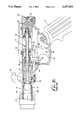
- FIG. 2 is a side view in partial cutaway of a gas powered gun having features of the invention
- FIG. 3 is a detailed view in partial cross-section of the gas powered gun shown in FIG. 2 wherein the hammer is in a ready-to-file position;
- FIG. 4 is a detailed view in partial cross-section of the gas gun shown in FIG. 2 wherein the hammer is shown during the firing operation;
- FIG. 5 is a detailed view in partial cross-section of the gas powered, gun shown in FIG. 2 wherein the components of the gun are shown as they exist immediately after the gun is fired;
- FIG. 6 is a detailed cross-sectional view of an alternative pressure seal usable in the invention.
- the invention is an improvement to a gas powered gun which is suitable for projecting lightweight projectiles, such as paint balls.
- An embodiment of the invention is shown in FIGS. 2-5.
- the gas powered gun of the invention 10 is an improvement over the prior art gas powered gun shown in FIGS. 1A and 1B.
- Both the gun of the invention 10 and the prior art comprises: (I) a handle 12, (II) a barrel 14, having a central bore 16, (III) a projectile repository 18 attached to the barrel 14, (IV) a projectile chamber 20 disposed within the central bore 16 of the barrel 14, (V) projectile insertion means for removing a projectile 21 from the projectile repository 18 and placing it into the projectile chamber 20, (VI) a bolt 22 affixed within the central bore 16 of the barrel 14 rearward of the projectile chamber 20, the bolt 22 having a central bore 24 which is in communication with the projectile chamber 20, (VII) a hammer 26 slidably disposed within the central bore 16 of the barrel 14 immediately rearward of the bolt 22, the hammer 26 having a central bore 28, (VIII) cocking means for attaching the hammer 26 to the bolt 22, (IX) trigger means for detaching
- the improvement of the invention comprises the further addition to the above-described prior art gas powered gun: a novel gas release actuation means in combination with a novel guide tube 33.
- the handle 12 can be of any shape suitable for gripping by the user.
- the handle 12 can be made out of any suitable material, including metals, plastics and woods.
- the barrel 14 is a hollow cylinder typically made of steel.
- the barrel 14 can, however, be made of other suitable materials capable of withstanding the structural and pressure forces present during cocking and firing.
- the central bore 16 of the barrel 14 has a forward end 34 which is in communication with the exterior of the gun 10 and a rearward end 36.
- the barrel 14 also has a longitudinal axis 38.
- the projectile repository 18 is attached to the exterior of the barrel 14.
- the projectile repository 18 can be any suitable container vessel capable of holding one or more of the lightweight projectiles 21.
- the projectile insertion means for removing a projectile 21 from the projectile repository 18 and placing it into the projectile chamber 20 can be any of the many suitable insertion means known in the art. Projectile insertion means whereby a projectile 21 is urged into the projectile chamber 20 by spring means or gas pressure means can be used.
- the projectile insertion means comprises a feed tube 42 which is in communication with both the projectile repository 18 and the projectile chamber 20.
- the projectile repository 18 is disposed above the projectile chamber 20 so that the lightweight projectile 21 will gravitate from the projectile repository 18 to the projectile chamber 20 via the feed tube 42.
- the bolt 22 is disposed within the central bore 16 of the barrel 14 rearward of the projectile chamber 20.
- the bolt 22 has a forward end 44 and a rearward end 46.
- the central bore 24 of the bolt 22 is in communication with the projectile chamber 20.
- the central bore 24 of the bolt 22 has a longitudinal axis which is coaxial with the longitudinal axis 38 of the barrel 14.
- the cross-sectional area of the central bore 24 of the bolt 22 in the forward end 44 of the bolt 22 is greater than cross-sectional area of the central bore 24 at the rearward end 46 of the bolt 22.
- the bolt 22 is slidably disposed within the central bore 16 of the barrel 14, and is slidable between a first, forward-most bolt position wherein the bolt 22 blocks the communication between the feed tube 42 and the projectile chamber 20 and a second, rearward-most bolt position wherein the bolt 22 does not block the communication between the feed tube 42 and the projectile chamber 20.
- the bolt 22 can be made of any suitable material, such as a plastic or a light metal.
- the hammer 26 is slidably disposed within the central bore 16 of the barrel 14 immediately rearward of the bolt 22.
- the hammer 26 has a forward end 47 and a rearward end 48.
- the central bore 28 of the hammer 26 has a longitudinal axis which is coaxial with the longitudinal axis 38 of the barrel 14.
- the hammer 26 can be made of any suitable material having sufficient mass to actuate the valve means described below and must be made of a material strong enough to withstand the mechanical and pressure forces generated during operation.
- the hammer is made out of a metal, such as a steel.
- the cocking means can be any of the many cocking means known generally in the art.
- the cocking means comprises a pump handle 49 disposed on the exterior of the barrel 14 so as to be slidable along the barrel 14.
- the pump handle 49 is mechanically engaged to the bolt 22 which is slidably disposed within the bore 16 of the barrel 14.
- the pump handle 49 can be slid along the exterior of the barrel 14 rearwardly so that the bolt 22 is slid between the first bolt position and the second bolt position.
- the stroke of the pump handle 49 is determined principally by the size of the projectile 21.
- the cocking means in the embodiment shown in the drawings further comprises a sear 50 which is swivably attached to the hammer 26 by a sear pivot 52.
- the sear 50 has a latch 54 which is adapted to engage a notch 56 defined by the exterior surface of the rearward end 46 of the bolt 22. When the latch 54 is engaged within the notch 56, the bolt 22 is held firmly in close proximity to the hammer 26.
- the sear 50 also comprises a sear cam 58 which cooperates during the firing operation with the trigger means, described below.
- the spring means for urging the hammer 26 away from the bolt 22 is provided in the embodiment shown in the drawings by a hammer spring 60 disposed between the hammer 26 and the bolt 22.
- the hammer spring 60 is so disposed that, when the hammer 26 is attached to the bolt 22 by the sear 50, the hammer spring 60 is in compression.
- the hammer spring 60 can be of any suitable strength.
- the hammer spring 60 has a spring tension between about 3 pounds and about 12 pounds.
- the trigger means for detaching the hammer 26 from the bolt 22 is provided in the embodiment shown in the drawings by a trigger 62 which is swivably attached on a trigger pivot 64.
- the trigger 62 is shaped with (1) a trigger projection 66 for contact with the user's finger, and (2) a trigger cam 68 which is disposed in close proximity to the sear cam 68.
- the trigger cam 68 rotates upwardly and contacts the sear cam 58.
- the sear 50 is caused to rotate about the sear pivot 52 so as to cause the latch 54 to disengage from the notch 56 of the bolt 22.
- the pressure chamber 30 is affixed within the rearward end 36 of the central bore 16 of the barrel 14.
- the pressure chamber 36 is in communication with a source of pressurized gas 32, such as a pressurized CO 2 canister.
- the pressure chamber 36 should be constructed so as to withstand at least about 300 psig., preferably 800 psig, and most preferably 2000 psig.
- a piercing pin 70 is used to release gas from a gas canister 32 into the pressure chamber 30.
- the pressurized gas can be one any of the several inexpensive, noncorrosive gases. Carbon dioxide is most typically used as a pressurized gas. Pressurized air and pressurized nitrogen can also be used.
- the valve means for releasing a discreet quantity of pressurized gas from the pressure chamber 30 is affixed immediately forward of the pressure chamber 30 in the central bore 16 of the barrel 14.
- the valve means is provided by a pressure release valve 72.
- the pressure release valve 72 comprises a valve seat 74, a valve tube 76 having at least one valve port 78, a sealing ring 80 and a backing nut 82.
- the pressure release valve 72 has two valve ports 78, each being about 0.18 inches in diameter.
- Spring means shown in the drawings as a valve spring 84, are provided to urge the backing nut 82 against the sealing ring 80 to cover and seal the ports 78.
- the valve spring 84 exerts between about 3 and about 12 pounds of force.
- FIG. 6 shows an alternative pressure release valve 72 useful in the invention.
- the valve seat 74a defines a flared opening having a frustoconical-shaped opening.
- a sealing ring 80a is especially dimensioned to fit within this frustoconical-shaped opening.
- the gas release actuation means for actuating the valve means and releasing a discreet quantity of gas from the pressure chamber comprises a gas release tube 86 for receiving the discreet quantity of pressurized gas.
- the gas release tube 86 is affixed to the valve tube 76 between the valve tube 76 and the hammer 26.
- the valve tube 76 and the gas release tube 86 are one and the same continuous structure.
- the gas release tube 86 has a longitudinal axis which is coaxial with the longitudinal axis 38 of the central bore 16 of the barrel 14.
- the gas release tube 86 also has a hammer engagement surface 88 for engaging and cooperating with the rearward end 48 of the hammer 26.
- the hammer engagement surface 88 is provided by a shoulder 90 defined on the external surface of the gas release tube 86.
- the gas release tube 86 is disposed within the valve means in such a way that, when the rearward end 48 of the hammer 26 is driven rearwardly within the central bore 16 of the barrel 14 by the force of the spring means, the kinetic energy of the hammer 26 is transferred to the gas release tube 86 by the engagement of the rearward end 48 of the hammer 26 and the hammer engagement surface 88.
- the guide tube 33 can be made from any suitable material which can withstand the forces associated with continual sliding contact with the interior surface of the central bore 24 of the bolt 22.
- the gas release tube is made of a steel and the combined mass of the hammer 26, sear 50, and guide tube 33 is between about 2 and 3 ounces, preferably between about 1.5 and about 1.9 ounces.
- the guide tube 33 is adapted to slide smoothly within the central bore 24 of the bolt 22.
- the exterior surface of the guide tube 33 is dimensioned to be in close tolerance with the central bore 24 of the bolt 22.
- the exterior surface of the guide tube is cylindrical as is the central bore 24 of the bolt 22 and the difference between the outside diameter of the guide tube 33 and the inside diameter of the central bore 24 of the bolt 22 is less than about 0.01 inches, most preferably between about 0.002 inches and 0.005 inches.
- the length of the guide tube 33 should be at least twice the outside diameter of the guide tube 33.
- the interior surface of the guide tube 33 is cylindrical and has a diameter between about 0.12 inches and about 0.22 inches. Also in a typical embodiment, the exterior surface of the guide tube 33 is cylindrical and has an outside diameter of between about 3/8 of an inch and 11/16 of an inch.
- the guide tube 33 is disposed within the central bore 28 of the hammer 26. In a most preferred embodiment, the guide tube 33 is press fit into the central bore 28 of the hammer 26 from the forward end 47 of the hammer 26. In this most preferred embodiment, the guide tube 33 can be firmly held within the central bore 28 of the hammer 26 by swagging the rearward-most end of the guide tube 33 to a mating taper within the central bore 28 of the hammer 26 in the rearward end 48 of the hammer 26.
- FIGS. 2-5 illustrate a typical firing sequence for the invention 10.
- FIG. 3 shows the gun 10 in the ready-to-fire position with a lightweight projectile 21 disposed within the projectile chamber 20.
- the hammer 26 is attached to the bolt 22 by the sear 50.
- the hammer spring 60 is in compression.
- the trigger projection 66 is pulled rearwardly by the user, the trigger 62 rotates around the trigger pivot 64 causing the trigger cam 68 to engage the sear cam 58.
- This action causes the sear 50 to rotate about the sear pivot 52 disengaging the latch 54 from the notch 56.
- the hammer 26 is thereby released from the bolt 22 and the hammer spring 60 urges the hammer 26 rearwardly toward the gas release tube 86.
- FIG. 3 shows the gun 10 in the ready-to-fire position with a lightweight projectile 21 disposed within the projectile chamber 20.
- the hammer 26 is attached to the bolt 22 by the sear 50.
- the hammer spring 60 is in compression
- the improved gun of the invention 10 differs principally from the prior art gun by the fact that the elongated gas release tube 86 of the prior art has been replaced in the improved gun of the invention 10 by a shortened gas release tube 86 which is adapted to cooperate with the central bore 28 of the hammer 26 and the guide tube 33.
- the gas release tube 86, the central bore 28 of the hammer 26 and the guide tube 33 cooperate to provide a single, continuous conduit leading into the central bore 24 of the bolt 22.
- the guide tube 33 slides smoothly within the central bore 24 of the bolt 22 to guide the hammer 26 rearwardly smoothly and without wobble.
- the hammer 26 in the prior art gun wobbles during the firing operation because it is only “guided” by the interaction of the interior surface of the barrel 14 and the exterior surface of the hammer 26. This "guidance” has been found to be most imperfect, causing excessive wear on the hammer 26 and the gas release tube 86 and inaccuracy in operation.
- the hammer 26 in the gun of the invention 10 slides on the other hand, smoothly rearwardly towards the gas release tube 86, guided by the close cooperation between the guide tube 33 and the central bore 24 of the bolt 22.
- the hammer 26 therefore, always strikes the hammer engagement surface 88 of the gas release tube 86 in a "flush” manner. This minimizes wear and tear on the hammer exterior and on the hammer/gas release tube interface, and results in a consistent quantity of gas being released from the valve means.
Abstract
Description
Claims (20)
Priority Applications (2)
| Application Number | Priority Date | Filing Date | Title |
|---|---|---|---|
| US07/916,527 US5257614A (en) | 1992-07-20 | 1992-07-20 | Gas powered gun |
| US08/055,640 US5339791A (en) | 1992-07-20 | 1993-04-30 | Gas powered gun |
Applications Claiming Priority (1)
| Application Number | Priority Date | Filing Date | Title |
|---|---|---|---|
| US07/916,527 US5257614A (en) | 1992-07-20 | 1992-07-20 | Gas powered gun |
Related Child Applications (1)
| Application Number | Title | Priority Date | Filing Date |
|---|---|---|---|
| US08/055,640 Continuation-In-Part US5339791A (en) | 1992-07-20 | 1993-04-30 | Gas powered gun |
Publications (1)
| Publication Number | Publication Date |
|---|---|
| US5257614A true US5257614A (en) | 1993-11-02 |
Family
ID=25437415
Family Applications (1)
| Application Number | Title | Priority Date | Filing Date |
|---|---|---|---|
| US07/916,527 Expired - Lifetime US5257614A (en) | 1992-07-20 | 1992-07-20 | Gas powered gun |
Country Status (1)
| Country | Link |
|---|---|
| US (1) | US5257614A (en) |
Cited By (77)
| Publication number | Priority date | Publication date | Assignee | Title |
|---|---|---|---|---|
| US5348059A (en) * | 1993-09-07 | 1994-09-20 | Air America | Multi function refill adaptor for gas operated airguns |
| US5349938A (en) * | 1993-04-22 | 1994-09-27 | Farrell Kenneth R | Reciprocatable barrel pneumatic gun |
| US5497758A (en) * | 1994-06-23 | 1996-03-12 | Dobbins; Jerrold M. | Compressed gas powered gun |
| US5509399A (en) * | 1995-01-12 | 1996-04-23 | Poor; Keith A. | Semi-automatic fluid powered gun |
| US5515838A (en) * | 1994-03-24 | 1996-05-14 | Donald R. Mainland | Paint ball gun |
| WO1996034247A1 (en) * | 1995-04-28 | 1996-10-31 | Sullivan Brian E | Gas powered repeating gun |
| US5586545A (en) * | 1995-10-02 | 1996-12-24 | Mccaslin; John A. | Compressed gas gun |
| US5613483A (en) * | 1995-11-09 | 1997-03-25 | Lukas; Michael A. | Gas powered gun |
| US5778868A (en) * | 1997-02-03 | 1998-07-14 | K.K.M. Inc. | Pneumatic gun |
| US5896850A (en) * | 1997-06-27 | 1999-04-27 | Sullivan, Jr.; Dennis G. | Paintball gun with sight rail cover |
| US5913303A (en) * | 1997-10-21 | 1999-06-22 | Kotsiopoulos; Thomas G. | Trigger mechanism for compressed gas powered weapons or the like |
| US5954043A (en) * | 1996-07-18 | 1999-09-21 | Universal Propulsion Company, Inc. | Less lethal weapon attachable to lethal weapon including valve arrangement |
| US5993215A (en) * | 1998-05-15 | 1999-11-30 | Kotsiopoulos; Thomas G. | Training weapon with trigger actuated indicator light |
| US6142058A (en) * | 1996-07-18 | 2000-11-07 | Mayville; Wayne R. | Less lethal weapon attachable to lethal weapon including valve arrangement |
| US6158424A (en) * | 1997-12-10 | 2000-12-12 | Western Arms | Model gun with automatic bullet supplying mechanism |
| US6226915B1 (en) | 1998-03-25 | 2001-05-08 | Thomas G. Kotsiopoulos | Forward angled grip for hand-held weapons and the like |
| US6516791B2 (en) * | 2000-11-20 | 2003-02-11 | Zap Paintball Inc. | Electrically operated paintball gun |
| US20030047175A1 (en) * | 2001-07-26 | 2003-03-13 | Kenneth Farrell | Pneumatic gun |
| US6622714B2 (en) * | 2001-04-11 | 2003-09-23 | Liang Guodong | Cap gun with continuous shooting feature |
| US6662797B1 (en) * | 2000-11-27 | 2003-12-16 | Pursuit Marketing, Inc. | Transparent gun elements |
| US6708685B2 (en) | 2002-03-06 | 2004-03-23 | National Paintball Supply, Inc. | Compressed gas-powered projectile accelerator |
| US20040065310A1 (en) * | 2002-03-06 | 2004-04-08 | National Paintball Supply, Inc. | Compressed gas-powered projectile accelerator |
| US20040089280A1 (en) * | 2002-10-30 | 2004-05-13 | Western Arms | Toy gun |
| US20040144357A1 (en) * | 2003-01-24 | 2004-07-29 | Adams Joseph S. | Multiple-front combustion chamber system with a fuel/air management system |
| US20040144377A1 (en) * | 1999-03-19 | 2004-07-29 | Jerry Dobbins | Spring assist for launch from compressed gas gun |
| US20050115552A1 (en) * | 1999-03-19 | 2005-06-02 | Dobbins Jerrold M. | Discharge port and breech for compressed gas gun |
| US20050120983A1 (en) * | 2003-12-09 | 2005-06-09 | Adams Joseph S. | Scavenging system for intermittent linear motor |
| US20050217655A1 (en) * | 2001-07-03 | 2005-10-06 | Smart Parts, Inc. | Paintball gun having an in-line penumatic assembly |
| US20060032487A1 (en) * | 2004-08-12 | 2006-02-16 | Tippmann Dennis J Sr | Apparatus and method for firing a projectile |
| US20060037597A1 (en) * | 2004-07-13 | 2006-02-23 | National Paintball Supply, Inc. | Valve for compressed gas gun |
| US20060169265A1 (en) * | 2005-02-03 | 2006-08-03 | Lai Bao S | Shooting structure of a paint bullet gun |
| US20060207586A1 (en) * | 2003-10-27 | 2006-09-21 | Danial Jones | Pneumatic assembly for a paintball gun |
| US20060207585A1 (en) * | 2005-03-18 | 2006-09-21 | Chu-Min Liang | Bullet delivery device for air guns |
| US20060225717A1 (en) * | 2005-04-07 | 2006-10-12 | Buzz Bee Toys, Inc. | Toy gun for launching an elongated dart and a method of using pressurized air to launch an elongated dart from a toy gun |
| GB2426041A (en) * | 2005-05-13 | 2006-11-15 | Evolve Paintball Ltd | Gas operated gun mechanism |
| US20070017497A1 (en) * | 2002-03-06 | 2007-01-25 | Masse Robert K | Compressed gas gun having reduced breakaway-friction and high pressure dynamic separable seal flow control device |
| US20070028909A1 (en) * | 2004-12-15 | 2007-02-08 | National Paintball Supply, Inc. | Paintball marker with ball velocity control |
| US20070113835A1 (en) * | 2005-01-05 | 2007-05-24 | Hsin-Cheng Yeh | Paintball gun |
| US20070151548A1 (en) * | 2005-10-22 | 2007-07-05 | Long Robert M | Valve Assembly for Paintball Guns and the Like, and Improved Guns Incorporating the Assembly |
| US20070151549A1 (en) * | 2005-12-01 | 2007-07-05 | Aj Acquisitions I Llc | Paintball marker |
| US20070163564A1 (en) * | 2006-01-19 | 2007-07-19 | Yiauguo Gan | Gas gun having pressure driving device |
| US20070163561A1 (en) * | 2006-01-19 | 2007-07-19 | Yiauguo Gan | Gas gun having air driving device |
| US20070163562A1 (en) * | 2006-01-19 | 2007-07-19 | Yiauguo Gan | Gas gun having pneumatic driving device |
| US20070209650A1 (en) * | 2006-03-08 | 2007-09-13 | Smart Parts, Inc. | Bolt for pneumatic paintball gun |
| US20070235014A1 (en) * | 2000-04-03 | 2007-10-11 | Tiberius Benjamin T | Semi-automatic-firing, compressed-gas gun |
| US20070235016A1 (en) * | 2006-04-06 | 2007-10-11 | Colin Moritz | Pneumatic Single Pulse Driven Bolt and Valve Assembly |
| US20080099005A1 (en) * | 2006-10-27 | 2008-05-01 | Dye Precision, Inc. | Paintball marker |
| US20080127959A1 (en) * | 2006-01-19 | 2008-06-05 | Yiauguo Gan | Gas Gun Having An Air Driving Device |
| US20080127960A1 (en) * | 2006-01-19 | 2008-06-05 | Yiauguo Gan | Gas Gun Having A Pressure Driving Device |
| US20080135031A1 (en) * | 2006-01-19 | 2008-06-12 | Yiauguo Gan | Gas Gun Having A Pneumatic Driving Device |
| US7395819B2 (en) | 2004-07-16 | 2008-07-08 | Kee Action Sports | Gas governor, snatch grip, and link pin for paintball gun |
| US20080245351A1 (en) * | 2006-10-27 | 2008-10-09 | Dye Precision, Inc. | Paintball marker |
| US7594503B2 (en) | 2004-05-25 | 2009-09-29 | Dye Precision, Inc. | Pneumatic paintball marker |
| US7640927B1 (en) * | 2005-09-22 | 2010-01-05 | Lester Broersma | Multiple function paintball marker bolt |
| US7665396B1 (en) | 2006-12-04 | 2010-02-23 | Tippmann Sports, Llc | Projectile launcher |
| US20100071680A1 (en) * | 2008-09-19 | 2010-03-25 | Shu-Mei Tseng | Pneumatic toy gun |
| US7686005B2 (en) | 2003-01-29 | 2010-03-30 | Adams Joseph S | Combustion-gas-powered paintball marker |
| US7712463B2 (en) | 2006-05-25 | 2010-05-11 | Kee Action Sports I Llc | Self-regulating valve assembly |
| US7762248B1 (en) | 2006-11-07 | 2010-07-27 | Rob Squire | Magnetic paint ball gun bolt apparatus |
| US7765998B2 (en) | 2006-09-28 | 2010-08-03 | Dye Precision, Inc. | Anti-chop eyes for a paintball marker |
| US20110048395A1 (en) * | 2009-08-28 | 2011-03-03 | Maruzen Company Limited | Toy gun |
| US7913679B2 (en) | 2004-06-10 | 2011-03-29 | Kee Action Sports I Llc | Valve assembly for a compressed gas gun |
| US20110088675A1 (en) * | 2009-10-19 | 2011-04-21 | Planet Eclipse Limited | Bolt and valve mechanism that uses less gas |
| US8006680B1 (en) | 2004-06-21 | 2011-08-30 | Rob Squire | Magnetic paint ball gun apparatus |
| US8015907B2 (en) | 2004-08-12 | 2011-09-13 | Tippmann Sports, Llc | Projectile launcher |
| US20110265775A1 (en) * | 2010-04-28 | 2011-11-03 | Maruzen Company Limited | Toy gun |
| US8074632B2 (en) | 2004-07-16 | 2011-12-13 | Kee Action Sports I Llc | Variable pneumatic sear for paintball gun |
| US8113189B2 (en) | 2004-07-16 | 2012-02-14 | Kee Action Sports I Llc | Compressed gas gun having gas governor |
| US8413644B2 (en) | 2002-03-06 | 2013-04-09 | Kee Action Sports I Llc | Compressed gas gun having reduced breakaway-friction and high pressure dynamic separable seal and flow control and valving device |
| JP2014501903A (en) * | 2010-11-30 | 2014-01-23 | 廖▲彦▼▲テイ▼ | Airsoft gun structure with improved reality and a safe gasification system for compressed gas cartridges |
| US20150300771A1 (en) * | 2015-06-28 | 2015-10-22 | Jui-Fu Tseng | Firing mechanism of airsoft gun |
| EP3064884A1 (en) * | 2015-03-02 | 2016-09-07 | FX Airguns AB | A gas powered gun |
| US9523550B2 (en) * | 2012-08-29 | 2016-12-20 | Real Action Paintball (Rap4), Inc. | Projectile launcher able to launch an object using a hammer |
| US20170045328A1 (en) * | 2014-11-24 | 2017-02-16 | William S. Nachefski | Efficient high-velocity compressed gas-powered gun |
| US9605924B1 (en) | 2015-10-22 | 2017-03-28 | John A. McCaslin | Compressed gas gun with improved operating mechanism |
| US10113829B2 (en) * | 2014-11-24 | 2018-10-30 | William S. Nachefski | Efficient high-velocity compressed gas-powered gun |
| US10401121B2 (en) * | 2015-04-03 | 2019-09-03 | Polarstar Engineering & Machine Llc | Pneumatic projectile launching system |
Citations (10)
| Publication number | Priority date | Publication date | Assignee | Title |
|---|---|---|---|---|
| US964810A (en) * | 1907-12-23 | 1910-07-19 | David J Rieger | Air-gun. |
| US3199501A (en) * | 1959-12-31 | 1965-08-10 | Bertschinger Jakob | Gas-operated, manually cocked shooting device |
| US3204625A (en) * | 1963-03-22 | 1965-09-07 | Bob G Shepherd | Gas-operated pistol |
| US3494344A (en) * | 1966-12-14 | 1970-02-10 | Crosman Arms Co Inc | Gas-operated gun |
| US3572310A (en) * | 1968-02-02 | 1971-03-23 | Kensuke Chiba | Compressed gas gun and valve therefor |
| US3788298A (en) * | 1972-06-19 | 1974-01-29 | Victor Comptometer Corp | Compressed gas gun with trigger operated hammer release latching structure |
| US4531503A (en) * | 1984-02-21 | 1985-07-30 | Shepherd Robert G | Fluid pressure repeating pistol with unitary barrel and hammer assembly |
| CA1264128A (en) * | 1988-09-29 | 1990-01-02 | Aldo Perrone | Air gun |
| US4936282A (en) * | 1988-12-09 | 1990-06-26 | Dobbins Jerrold M | Gas powered gun |
| US5078118A (en) * | 1989-08-13 | 1992-01-07 | Brass Eagle Inc. | Breech construction for air gun |
-
1992
- 1992-07-20 US US07/916,527 patent/US5257614A/en not_active Expired - Lifetime
Patent Citations (10)
| Publication number | Priority date | Publication date | Assignee | Title |
|---|---|---|---|---|
| US964810A (en) * | 1907-12-23 | 1910-07-19 | David J Rieger | Air-gun. |
| US3199501A (en) * | 1959-12-31 | 1965-08-10 | Bertschinger Jakob | Gas-operated, manually cocked shooting device |
| US3204625A (en) * | 1963-03-22 | 1965-09-07 | Bob G Shepherd | Gas-operated pistol |
| US3494344A (en) * | 1966-12-14 | 1970-02-10 | Crosman Arms Co Inc | Gas-operated gun |
| US3572310A (en) * | 1968-02-02 | 1971-03-23 | Kensuke Chiba | Compressed gas gun and valve therefor |
| US3788298A (en) * | 1972-06-19 | 1974-01-29 | Victor Comptometer Corp | Compressed gas gun with trigger operated hammer release latching structure |
| US4531503A (en) * | 1984-02-21 | 1985-07-30 | Shepherd Robert G | Fluid pressure repeating pistol with unitary barrel and hammer assembly |
| CA1264128A (en) * | 1988-09-29 | 1990-01-02 | Aldo Perrone | Air gun |
| US4936282A (en) * | 1988-12-09 | 1990-06-26 | Dobbins Jerrold M | Gas powered gun |
| US5078118A (en) * | 1989-08-13 | 1992-01-07 | Brass Eagle Inc. | Breech construction for air gun |
Cited By (132)
| Publication number | Priority date | Publication date | Assignee | Title |
|---|---|---|---|---|
| US5349938A (en) * | 1993-04-22 | 1994-09-27 | Farrell Kenneth R | Reciprocatable barrel pneumatic gun |
| US5348059A (en) * | 1993-09-07 | 1994-09-20 | Air America | Multi function refill adaptor for gas operated airguns |
| US5515838A (en) * | 1994-03-24 | 1996-05-14 | Donald R. Mainland | Paint ball gun |
| US5497758A (en) * | 1994-06-23 | 1996-03-12 | Dobbins; Jerrold M. | Compressed gas powered gun |
| US5509399A (en) * | 1995-01-12 | 1996-04-23 | Poor; Keith A. | Semi-automatic fluid powered gun |
| WO1996034247A1 (en) * | 1995-04-28 | 1996-10-31 | Sullivan Brian E | Gas powered repeating gun |
| US5771875A (en) * | 1995-04-28 | 1998-06-30 | Sullivan; Brian E. | Gas powered repeating gun |
| US5586545A (en) * | 1995-10-02 | 1996-12-24 | Mccaslin; John A. | Compressed gas gun |
| US5613483A (en) * | 1995-11-09 | 1997-03-25 | Lukas; Michael A. | Gas powered gun |
| US6142058A (en) * | 1996-07-18 | 2000-11-07 | Mayville; Wayne R. | Less lethal weapon attachable to lethal weapon including valve arrangement |
| US5954043A (en) * | 1996-07-18 | 1999-09-21 | Universal Propulsion Company, Inc. | Less lethal weapon attachable to lethal weapon including valve arrangement |
| US5778868A (en) * | 1997-02-03 | 1998-07-14 | K.K.M. Inc. | Pneumatic gun |
| US5896850A (en) * | 1997-06-27 | 1999-04-27 | Sullivan, Jr.; Dennis G. | Paintball gun with sight rail cover |
| US5913303A (en) * | 1997-10-21 | 1999-06-22 | Kotsiopoulos; Thomas G. | Trigger mechanism for compressed gas powered weapons or the like |
| US6158424A (en) * | 1997-12-10 | 2000-12-12 | Western Arms | Model gun with automatic bullet supplying mechanism |
| US6226915B1 (en) | 1998-03-25 | 2001-05-08 | Thomas G. Kotsiopoulos | Forward angled grip for hand-held weapons and the like |
| US5993215A (en) * | 1998-05-15 | 1999-11-30 | Kotsiopoulos; Thomas G. | Training weapon with trigger actuated indicator light |
| US20050115552A1 (en) * | 1999-03-19 | 2005-06-02 | Dobbins Jerrold M. | Discharge port and breech for compressed gas gun |
| US20040144377A1 (en) * | 1999-03-19 | 2004-07-29 | Jerry Dobbins | Spring assist for launch from compressed gas gun |
| US20070235014A1 (en) * | 2000-04-03 | 2007-10-11 | Tiberius Benjamin T | Semi-automatic-firing, compressed-gas gun |
| US6516791B2 (en) * | 2000-11-20 | 2003-02-11 | Zap Paintball Inc. | Electrically operated paintball gun |
| US6662797B1 (en) * | 2000-11-27 | 2003-12-16 | Pursuit Marketing, Inc. | Transparent gun elements |
| US6622714B2 (en) * | 2001-04-11 | 2003-09-23 | Liang Guodong | Cap gun with continuous shooting feature |
| US20070215133A1 (en) * | 2001-07-03 | 2007-09-20 | Smart Parts, Inc. | Paintball gun having a pneumatic firing valve |
| US20050217655A1 (en) * | 2001-07-03 | 2005-10-06 | Smart Parts, Inc. | Paintball gun having an in-line penumatic assembly |
| US7121272B2 (en) * | 2001-07-03 | 2006-10-17 | Smart Parts, Inc. | Paintball gun having an in-line pneumatic assembly |
| US6832605B2 (en) * | 2001-07-26 | 2004-12-21 | Kenneth Farrell | Pneumatic gun |
| US20030047175A1 (en) * | 2001-07-26 | 2003-03-13 | Kenneth Farrell | Pneumatic gun |
| US20040065310A1 (en) * | 2002-03-06 | 2004-04-08 | National Paintball Supply, Inc. | Compressed gas-powered projectile accelerator |
| US8191543B2 (en) | 2002-03-06 | 2012-06-05 | Kee Action Sports I Llc | Compressed gas-powered projectile accelerator |
| US9476669B2 (en) | 2002-03-06 | 2016-10-25 | Gi Sportz Direct Llc | Compressed gas gun |
| US8739770B2 (en) * | 2002-03-06 | 2014-06-03 | Kee Action Sports I Llc | Compressed gas-powered projectile accelerator |
| US9903683B2 (en) | 2002-03-06 | 2018-02-27 | Gi Sportz Direct Llc | Compressed gas gun |
| US10323901B2 (en) | 2002-03-06 | 2019-06-18 | National Paintball Supply, Inc. | Compressed gas gun |
| US20130092141A1 (en) * | 2002-03-06 | 2013-04-18 | Kee Action Sports I Llc | Compressed gas-powered projectile accelerator |
| US8413644B2 (en) | 2002-03-06 | 2013-04-09 | Kee Action Sports I Llc | Compressed gas gun having reduced breakaway-friction and high pressure dynamic separable seal and flow control and valving device |
| US10914545B2 (en) * | 2002-03-06 | 2021-02-09 | Kore Outdoor (Us), Inc. | Compressed gas gun |
| US20090032003A1 (en) * | 2002-03-06 | 2009-02-05 | Aj Acquisition I Llc | Compressed gas-powered projectile accelerator |
| US6708685B2 (en) | 2002-03-06 | 2004-03-23 | National Paintball Supply, Inc. | Compressed gas-powered projectile accelerator |
| US7886731B2 (en) | 2002-03-06 | 2011-02-15 | Kee Action Sports I Llc | Compressed gas gun having reduced breakaway-friction and high pressure dynamic separable seal flow control device |
| US20070017497A1 (en) * | 2002-03-06 | 2007-01-25 | Masse Robert K | Compressed gas gun having reduced breakaway-friction and high pressure dynamic separable seal flow control device |
| US8272373B2 (en) | 2002-03-06 | 2012-09-25 | Kee Action Sports I Llc | Compressed gas-powered projectile accelerator |
| US8336532B2 (en) | 2002-03-06 | 2012-12-25 | Kee Action Sports I Llc | Compressed gas-powered projectile accelerator |
| US7237545B2 (en) * | 2002-03-06 | 2007-07-03 | Aj Acquisition I Llc | Compressed gas-powered projectile accelerator |
| US20040089280A1 (en) * | 2002-10-30 | 2004-05-13 | Western Arms | Toy gun |
| US6912988B2 (en) | 2003-01-24 | 2005-07-05 | Joseph S. Adams | Multiple-front combustion chamber system with a fuel/air management system |
| US20040144357A1 (en) * | 2003-01-24 | 2004-07-29 | Adams Joseph S. | Multiple-front combustion chamber system with a fuel/air management system |
| US7686005B2 (en) | 2003-01-29 | 2010-03-30 | Adams Joseph S | Combustion-gas-powered paintball marker |
| US20060207586A1 (en) * | 2003-10-27 | 2006-09-21 | Danial Jones | Pneumatic assembly for a paintball gun |
| US7640925B2 (en) * | 2003-10-27 | 2010-01-05 | Smart Parts, Inc. | Pneumatic assembly for a paintball gun |
| US20050120983A1 (en) * | 2003-12-09 | 2005-06-09 | Adams Joseph S. | Scavenging system for intermittent linear motor |
| US6932031B2 (en) | 2003-12-09 | 2005-08-23 | Joseph S. Adams | Scavenging system for intermittent linear motor |
| US8397705B2 (en) | 2004-05-25 | 2013-03-19 | Dye Precision, Inc. | Pneumatic paintball marker |
| US20100071679A1 (en) * | 2004-05-25 | 2010-03-25 | Dye Precision, Inc. | Pneumatic paintball marker |
| US8186338B2 (en) | 2004-05-25 | 2012-05-29 | Dye Precision, Inc. | Pneumatic paintball marker |
| US7594503B2 (en) | 2004-05-25 | 2009-09-29 | Dye Precision, Inc. | Pneumatic paintball marker |
| US7913679B2 (en) | 2004-06-10 | 2011-03-29 | Kee Action Sports I Llc | Valve assembly for a compressed gas gun |
| US8006680B1 (en) | 2004-06-21 | 2011-08-30 | Rob Squire | Magnetic paint ball gun apparatus |
| US7624726B2 (en) | 2004-07-13 | 2009-12-01 | Kee Action Sports I Llc | Valve for compressed gas gun |
| US20060037597A1 (en) * | 2004-07-13 | 2006-02-23 | National Paintball Supply, Inc. | Valve for compressed gas gun |
| US8555868B2 (en) | 2004-07-16 | 2013-10-15 | Kee Action Sports I Llc | Variable pneumatic sear for paintball gun |
| US8505525B2 (en) | 2004-07-16 | 2013-08-13 | Kee Action Sports I Llc | Compressed gas gun having gas governor |
| US8113189B2 (en) | 2004-07-16 | 2012-02-14 | Kee Action Sports I Llc | Compressed gas gun having gas governor |
| US7921837B2 (en) | 2004-07-16 | 2011-04-12 | Kee Action Sports I Llc | Gas governor, snatch grip, and link pin for paintball gun |
| US7395819B2 (en) | 2004-07-16 | 2008-07-08 | Kee Action Sports | Gas governor, snatch grip, and link pin for paintball gun |
| US8074632B2 (en) | 2004-07-16 | 2011-12-13 | Kee Action Sports I Llc | Variable pneumatic sear for paintball gun |
| US9746279B2 (en) | 2004-07-16 | 2017-08-29 | Gi Sportz Direct Llc | Compressed gas gun having removable firing mechanism |
| US8534272B2 (en) | 2004-07-16 | 2013-09-17 | Kee Action Sports I Llc | Variable pneumatic sear for paintball gun |
| US10024626B2 (en) | 2004-07-16 | 2018-07-17 | Gi Sportz Direct Llc | Compressed gas gun |
| US8176908B2 (en) | 2004-07-16 | 2012-05-15 | Kee Action Sports I Llc | Variable pneumatic sear for paintball gun |
| US20230349665A1 (en) * | 2004-07-16 | 2023-11-02 | Kore Outdoor (Us), Inc. | Compressed gas gun |
| US8573191B2 (en) | 2004-07-16 | 2013-11-05 | Kee Action Sports I, Llc | Variable pneumatic sear for paintball gun |
| US20220299292A1 (en) * | 2004-07-16 | 2022-09-22 | Kore Outdoor (Us), Inc. | Compressed gas gun |
| US11639838B2 (en) * | 2004-07-16 | 2023-05-02 | Kore Outdoor (Us), Inc. | Compressed gas gun |
| US20060032487A1 (en) * | 2004-08-12 | 2006-02-16 | Tippmann Dennis J Sr | Apparatus and method for firing a projectile |
| US8015907B2 (en) | 2004-08-12 | 2011-09-13 | Tippmann Sports, Llc | Projectile launcher |
| US7770504B2 (en) | 2004-08-12 | 2010-08-10 | Tippmann Sports, Llc | Apparatus and method for firing a projectile |
| US20070028909A1 (en) * | 2004-12-15 | 2007-02-08 | National Paintball Supply, Inc. | Paintball marker with ball velocity control |
| US7290537B2 (en) * | 2005-01-05 | 2007-11-06 | Sunworld Industrial Co., Ltd. | Paintball gun |
| US20070113835A1 (en) * | 2005-01-05 | 2007-05-24 | Hsin-Cheng Yeh | Paintball gun |
| US20060169265A1 (en) * | 2005-02-03 | 2006-08-03 | Lai Bao S | Shooting structure of a paint bullet gun |
| US20060207585A1 (en) * | 2005-03-18 | 2006-09-21 | Chu-Min Liang | Bullet delivery device for air guns |
| US20060225717A1 (en) * | 2005-04-07 | 2006-10-12 | Buzz Bee Toys, Inc. | Toy gun for launching an elongated dart and a method of using pressurized air to launch an elongated dart from a toy gun |
| US7537001B2 (en) * | 2005-04-07 | 2009-05-26 | Buzz Bee Toys, Inc. | Toy gun for launching an elongated dart and a method of using pressurized air to launch an elongated dart from a toy gun |
| GB2426041A (en) * | 2005-05-13 | 2006-11-15 | Evolve Paintball Ltd | Gas operated gun mechanism |
| US20100101550A1 (en) * | 2005-05-13 | 2010-04-29 | Black Market Sportz Limited | Gas operated gun mechanism |
| US7640927B1 (en) * | 2005-09-22 | 2010-01-05 | Lester Broersma | Multiple function paintball marker bolt |
| US20070151548A1 (en) * | 2005-10-22 | 2007-07-05 | Long Robert M | Valve Assembly for Paintball Guns and the Like, and Improved Guns Incorporating the Assembly |
| US7520275B2 (en) | 2005-10-22 | 2009-04-21 | Long Robert M | Valve assembly for paintball guns and the like, and improved guns incorporating the assembly |
| US20070151549A1 (en) * | 2005-12-01 | 2007-07-05 | Aj Acquisitions I Llc | Paintball marker |
| US7597096B2 (en) | 2006-01-19 | 2009-10-06 | Yiauguo Gan | Gas gun having an air driving device |
| US20080127960A1 (en) * | 2006-01-19 | 2008-06-05 | Yiauguo Gan | Gas Gun Having A Pressure Driving Device |
| US20080127959A1 (en) * | 2006-01-19 | 2008-06-05 | Yiauguo Gan | Gas Gun Having An Air Driving Device |
| US7597097B2 (en) | 2006-01-19 | 2009-10-06 | Yiauguo Gan | Gas gun having a pneumatic driving device |
| US7594505B2 (en) | 2006-01-19 | 2009-09-29 | Yiauguo Gan | Gas gun having a pressure driving device |
| US20080135031A1 (en) * | 2006-01-19 | 2008-06-12 | Yiauguo Gan | Gas Gun Having A Pneumatic Driving Device |
| US20070163562A1 (en) * | 2006-01-19 | 2007-07-19 | Yiauguo Gan | Gas gun having pneumatic driving device |
| US20070163561A1 (en) * | 2006-01-19 | 2007-07-19 | Yiauguo Gan | Gas gun having air driving device |
| US20070163564A1 (en) * | 2006-01-19 | 2007-07-19 | Yiauguo Gan | Gas gun having pressure driving device |
| US20070209650A1 (en) * | 2006-03-08 | 2007-09-13 | Smart Parts, Inc. | Bolt for pneumatic paintball gun |
| US7461646B2 (en) * | 2006-03-08 | 2008-12-09 | Smart Parts, Inc. | Bolt for pneumatic paintball gun |
| US20070235016A1 (en) * | 2006-04-06 | 2007-10-11 | Colin Moritz | Pneumatic Single Pulse Driven Bolt and Valve Assembly |
| US7712463B2 (en) | 2006-05-25 | 2010-05-11 | Kee Action Sports I Llc | Self-regulating valve assembly |
| US8316835B2 (en) | 2006-09-28 | 2012-11-27 | Dye Precision, Inc. | Anti-chop eyes for a paintball marker |
| US7765998B2 (en) | 2006-09-28 | 2010-08-03 | Dye Precision, Inc. | Anti-chop eyes for a paintball marker |
| US20080245351A1 (en) * | 2006-10-27 | 2008-10-09 | Dye Precision, Inc. | Paintball marker |
| US7997260B2 (en) * | 2006-10-27 | 2011-08-16 | Dye Precision, Inc. | Paintball marker |
| US20080099005A1 (en) * | 2006-10-27 | 2008-05-01 | Dye Precision, Inc. | Paintball marker |
| US7762248B1 (en) | 2006-11-07 | 2010-07-27 | Rob Squire | Magnetic paint ball gun bolt apparatus |
| US7665396B1 (en) | 2006-12-04 | 2010-02-23 | Tippmann Sports, Llc | Projectile launcher |
| US8267077B2 (en) * | 2007-10-05 | 2012-09-18 | Dye Precision, Inc. | Paintball marker |
| US20110297136A1 (en) * | 2007-10-05 | 2011-12-08 | Dye Precision, Inc. | Paintball marker |
| US7836872B2 (en) * | 2008-09-19 | 2010-11-23 | Shu-Mei Tseng | Pneumatic toy gun |
| US20100071680A1 (en) * | 2008-09-19 | 2010-03-25 | Shu-Mei Tseng | Pneumatic toy gun |
| US20110048395A1 (en) * | 2009-08-28 | 2011-03-03 | Maruzen Company Limited | Toy gun |
| US8109260B2 (en) * | 2009-08-28 | 2012-02-07 | Maruzen Company Limited | Toy gun |
| US20110088675A1 (en) * | 2009-10-19 | 2011-04-21 | Planet Eclipse Limited | Bolt and valve mechanism that uses less gas |
| US8201547B2 (en) | 2009-10-19 | 2012-06-19 | Planet Eclipse Limited | Bolt and valve mechanism that uses less gas |
| US8104463B2 (en) * | 2009-10-19 | 2012-01-31 | Planet Eclipse Limited | Bolt and valve mechanism that uses less gas |
| US8161957B2 (en) * | 2010-04-28 | 2012-04-24 | Maruzen Company Limited | Toy gun |
| US20110265775A1 (en) * | 2010-04-28 | 2011-11-03 | Maruzen Company Limited | Toy gun |
| JP2014501903A (en) * | 2010-11-30 | 2014-01-23 | 廖▲彦▼▲テイ▼ | Airsoft gun structure with improved reality and a safe gasification system for compressed gas cartridges |
| US9523550B2 (en) * | 2012-08-29 | 2016-12-20 | Real Action Paintball (Rap4), Inc. | Projectile launcher able to launch an object using a hammer |
| US9739564B2 (en) * | 2014-11-24 | 2017-08-22 | William S. Nachefski | Efficient high-velocity compressed gas-powered gun |
| US10113829B2 (en) * | 2014-11-24 | 2018-10-30 | William S. Nachefski | Efficient high-velocity compressed gas-powered gun |
| US20170045328A1 (en) * | 2014-11-24 | 2017-02-16 | William S. Nachefski | Efficient high-velocity compressed gas-powered gun |
| US9689642B2 (en) * | 2015-03-02 | 2017-06-27 | Fx Airguns Ab | Gas powered gun |
| US20160258710A1 (en) * | 2015-03-02 | 2016-09-08 | Fx Airguns Ab | Gas powered gun |
| EP3064884A1 (en) * | 2015-03-02 | 2016-09-07 | FX Airguns AB | A gas powered gun |
| US10401121B2 (en) * | 2015-04-03 | 2019-09-03 | Polarstar Engineering & Machine Llc | Pneumatic projectile launching system |
| US20150300771A1 (en) * | 2015-06-28 | 2015-10-22 | Jui-Fu Tseng | Firing mechanism of airsoft gun |
| US9605924B1 (en) | 2015-10-22 | 2017-03-28 | John A. McCaslin | Compressed gas gun with improved operating mechanism |
Similar Documents
| Publication | Publication Date | Title |
|---|---|---|
| US5257614A (en) | Gas powered gun | |
| US5339791A (en) | Gas powered gun | |
| US6220237B1 (en) | Compressed air toy gun | |
| US4936282A (en) | Gas powered gun | |
| US20030047175A1 (en) | Pneumatic gun | |
| US5634456A (en) | Semi-automatic gun | |
| US3561419A (en) | Cross bow with pneumatic cooking assembly | |
| RU2333446C2 (en) | Airgun pistol | |
| TWI407074B (en) | Electric air gun | |
| US20060180134A1 (en) | Combination solid projectile and paintball gun, and solid projectile adapter for paintball gun | |
| TWI420065B (en) | Toy gun | |
| AU717642B2 (en) | Model gun with automatic bullet supplying mechanism | |
| US20100101550A1 (en) | Gas operated gun mechanism | |
| US5156137A (en) | Projectile launcher | |
| TWI390173B (en) | Toy gun | |
| US6502568B2 (en) | Model gun in the type of revolver | |
| US20130192575A1 (en) | Reconfigurable Toy Gun | |
| EP2065668B1 (en) | Air gun | |
| US6203397B1 (en) | convertible air and water toy gun | |
| US2922412A (en) | Cartridge cylinder for a toy gun | |
| EP1491846A1 (en) | Gas supplying mechanism in a gas powered toy gun | |
| US5054464A (en) | Rapid fire gas powered projectile gun | |
| US6739324B2 (en) | Compressed air distributor | |
| GB1599505A (en) | Guns | |
| JPH0477240B2 (en) |
Legal Events
| Date | Code | Title | Description |
|---|---|---|---|
| STCF | Information on status: patent grant |
Free format text: PATENTED CASE |
|
| FPAY | Fee payment |
Year of fee payment: 4 |
|
| AS | Assignment |
Owner name: ADVANCED TACTICAL SYSTEMS, INC., MINNESOTA Free format text: ASSIGNMENT OF ASSIGNORS INTEREST;ASSIGNOR:SULLIVAN, BRIAN E.;REEL/FRAME:008723/0417 Effective date: 19970325 |
|
| REMI | Maintenance fee reminder mailed | ||
| FPAY | Fee payment |
Year of fee payment: 8 |
|
| SULP | Surcharge for late payment |
Year of fee payment: 7 |
|
| AS | Assignment |
Owner name: A.T. SYSTEMS, INC., MINNESOTA Free format text: ASSIGNMENT OF ASSIGNORS INTEREST;ASSIGNOR:ADVANCED TACTICAL SYSTEMS, INC.;REEL/FRAME:013221/0296 Effective date: 20010809 |
|
| FEPP | Fee payment procedure |
Free format text: PAYOR NUMBER ASSIGNED (ORIGINAL EVENT CODE: ASPN); ENTITY STATUS OF PATENT OWNER: SMALL ENTITY |
|
| FPAY | Fee payment |
Year of fee payment: 12 |