US5259046A - Article comprising an optical waveguide containing a fluorescent dopant - Google Patents
Article comprising an optical waveguide containing a fluorescent dopant Download PDFInfo
- Publication number
- US5259046A US5259046A US07/955,002 US95500292A US5259046A US 5259046 A US5259046 A US 5259046A US 95500292 A US95500292 A US 95500292A US 5259046 A US5259046 A US 5259046A
- Authority
- US
- United States
- Prior art keywords
- core
- optical fiber
- article according
- fiber
- waveguide
- Prior art date
- Legal status (The legal status is an assumption and is not a legal conclusion. Google has not performed a legal analysis and makes no representation as to the accuracy of the status listed.)
- Expired - Lifetime
Links
Images


Classifications
-
- H—ELECTRICITY
- H01—ELECTRIC ELEMENTS
- H01S—DEVICES USING THE PROCESS OF LIGHT AMPLIFICATION BY STIMULATED EMISSION OF RADIATION [LASER] TO AMPLIFY OR GENERATE LIGHT; DEVICES USING STIMULATED EMISSION OF ELECTROMAGNETIC RADIATION IN WAVE RANGES OTHER THAN OPTICAL
- H01S3/00—Lasers, i.e. devices using stimulated emission of electromagnetic radiation in the infrared, visible or ultraviolet wave range
- H01S3/05—Construction or shape of optical resonators; Accommodation of active medium therein; Shape of active medium
- H01S3/06—Construction or shape of active medium
- H01S3/063—Waveguide lasers, i.e. whereby the dimensions of the waveguide are of the order of the light wavelength
- H01S3/067—Fibre lasers
- H01S3/06708—Constructional details of the fibre, e.g. compositions, cross-section, shape or tapering
- H01S3/0672—Non-uniform radial doping
Definitions
- This invention pertains to articles that comprise an optical waveguide-based fluorescent device. More particularly, it pertains to such articles (e.g., optical communication systems) that comprise a silica-based optical waveguide whose core region comprises a fluorescent dopant, typically rare earth ions, exemplarily Er 3+ .
- a fluorescent dopant typically rare earth ions, exemplarily Er 3+ .
- silica-based optical fiber whose core region is doped with an appropriate luminescent (typically rare earth) species can serve as optical amplifier for signal radiation of an appropriate wavelength, or as a coherent radiation source, a laser. See, for instance, U.S. Pat. Nos. 4,923,279 and 5,058,976, both incorporated herein by reference.
- the '279 patent teaches that it is advantageous to provide a fiber with the highest concentration of the luminescent species (e.g., Er) at the center of the core, since such a distribution results in improved gain performance for a given pump power.
- the luminescent species e.g., Er
- the '976 patent discloses Er-doped fiber designs which can provide fiber having, inter alia, low amplification threshold and noise. Methods of making such fiber are also disclosed. See also B. Pedersen et al., Journal of Lightwave Technology, Vol. 9, p. 1105 (1991), which suggests fiber designs for single mode operation.
- FIG. 1 schematically shows the refractive index profile and Er-distribution of a prior art fiber
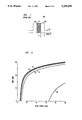
- FIG. 2 gives the computed relationship between amplifier gain and pump power, as a function of the fraction of pump power in the LP 11 mode, for a prior art fiber;
- FIG. 3 schematically depicts the refractive index profile and Er-distribution of an exemplary fiber according to the invention
- FIG. 4 gives the same computed relationship as in FIG. 2, but for a fiber according to the invention
- FIG. 5 gives the computed relationships between amplifier gain and pump power, assuming 10% variations in the cut-off wavelength, for a prior art fiber and for two fibers according to the invention.
- FIG. 6 schematically depicts an exemplary article according to the invention, namely, an optical fiber communication system that utilizes optical amplifiers according to the invention.
- an article e.g., an optical communication system
- an optical waveguide that is suitable for forming a fluorescent device (i.e., an optical amplifier, a laser or a superluminescent source), with the fluorescent dopant distribution in the waveguide being such that the fluorescent device is relatively insensitive to variations in cut-off wavelength, or such that the device is relatively insensitive to variations in pump power modal distribution.
- a fluorescent device i.e., an optical amplifier, a laser or a superluminescent source
- the invention may be embodied in planar as well as in circular optical waveguides.
- the latter are commonly referred to as "optical fiber".
- Both types of waveguides comprise a "core” that has relatively high refractive index and a “cladding” that has relatively low refractive index and that at least partially surrounds the core.
- an optical waveguide comprises a core and a cladding that at least partially surrounds the core and has an interface therewith.
- the core contains the fluorescent dopant (typically a rare earth such as Er, Nd, Yb, Sm, Tm and Pr) and has a center.
- the effective "radii" of the annular distribution are those radii at which the luminescent dopant concentration is 50% of the maximum luminescent dopant concentration.
- the equivalent core radius is the radius of the equivalent step index core.
- the fluorescent dopant distribution is such that the dopant concentration is substantially higher at a value of y ⁇ 0 (0 ⁇
- the luminescent species distribution typically is such that 0.5 ⁇
- ⁇ 1 and 0.2 ⁇ " ⁇ 0.5, where ⁇ "
- the "effective" distances are those distances at which the luminescent dopant concentration is 50% of the maximum dopant concentration.
- the invention may be embodied in any suitable glass system, but silica-based waveguides, especially silica-based fibers, are currently of greatest commercial interest. Furthermore, the invention may be practiced with any suitable fluorescent dopant, but rare earth dopants are currently of most commercial interest. In particular, for communication systems that use signal radiation of about 1.5-1.6 ⁇ m (e.g., 1.56 ⁇ m), Er is currently the dopant of greatest commercial interest.
- FIG. 1 schematically shows the refractive index profile and Er distribution of a prior art fiber 100, showing core region 101, cladding 102, and Er-doped core region 103.
- FIG. 2 shows the computed gain vs. 0.98 ⁇ m pump power for a prior art optical amplifier comprising fiber as shown in FIG. 1.
- the computation used a model due to A. A. M. Saleh et al., IEEE Photonics Technology Letters, Vol. 2, p. 714 (1990).
- the parameter ⁇ of FIG. 2 is the fraction of pump power present in the LP 11 mode.
- the gain of the prior art amplifier is quite strongly dependent on the distribution of the pump power between the waveguide modes.
- FIG. 3 schematically shows the refractive index profile and Er-distribution of a fiber 30 according to the invention, with numeral 31 referring to the annular Er-doped region having inner and outer radii r 1 and r 2 , respectively. If radius values are replaced by analogous values of the previously defined coordinate z, then FIG. 3 can represent an exemplary planar waveguide according to the invention.
- FIG. 4 shows the computed gain for an optical amplifier according to the invention, with ⁇ having the same meaning as in FIG. 2.
- the values of r 1 and r 2 are 0.7a and 0.95a, respectively.
- a design having approximately (e.g., within ⁇ 10% for r 1 , within -10% and a for r 2 ) these values for r 1 and r 2 results in robustness in amplifier behavior against changes in fractional pump power in the LP 11 mode and is currently preferred for 0.98 ⁇ m pumped amplifiers.
- r 1 and r 2 were determined by means of evaluations of the overlap integrals of the Er profile and the LP 01 and LP 11 modes, satisfying the requirement that the two overlap integrals be equal. However, satisfaction of this requirement is not a limitation on fiber designs according to the invention, and other requirements may be appropriate under special circumstances.
- the referred-to overlap integral is ##EQU1## where E(r) is the Er-distribution and ⁇ lm 2 is the model power envelope of the LP lm mode at the wavelength of interest, e.g., at 0.98 ⁇ m.
- the variables have their customary meaning.
- fibers according to the invention can provide robustness in amplifier behavior with respect to changes in cut-off wavelength. Such changes can be due to changes in the core/cladding normalized index difference ⁇ n and/or changes in core radius a. Real fiber typically exhibits at least minor variations in these (and other) parameters.
- the values of r 1 are 0, 0.37, 0.75, respectively, and those of r 2 are 0.25, 0.62 and 1, respectively, all in units of a.
- the prior art amplifier shows a drop in gain with a decrease in ⁇ c .
- the amplifier with Er at the core-cladding interface shows a marginal increase in gain (at the expense of relatively high threshold power and relatively low overall gain).
- the novel design with r 2 ⁇ a shows a minimum variation in performance, resulting in improved manufacturability.
- Currently preferred embodiments of the invention have r 2 /a in the range 0.62 ⁇ 10% and ⁇ ' in the range 0.25 ⁇ 10%.
- FIG. 6 schematically depicts an optical fiber communication system 10 that can advantageously comprise fiber according to the invention.
- the system comprises transmitter 11 and receiver 19, with a length of optical fiber (comprising a multiplicity each of transmission fibers 14 and amplifier fibers 15) therebetween.
- the output radiation 13 of the transmitter is modulated in accordance with signal 12 and is coupled into the optical fiber, is transmitted therethrough and amplified, and radiation 13' is detected in receiver 19, with output 12' available for utilization.
- the system further comprises pump lasers 17 whose output radiation is coupled into the optical fiber using known means 16, e.g., directional couplers.
- Known means 18 can be used to couple amplifier fibers 14 and transmission fibers 15.
- Means 16 cause pump radiation to travel "down stream" in the amplifier fiber.
- At least one of the amplifier sections comprises fiber according to the invention.
- Optical fiber according to the invention can be made by any suitably adapted conventional method, including MCVD and VAD.
- the Er-containing annular region of an Er-doped silica-based fiber according to the invention advantageously also contains Al and, possibly, Ge.
- the maximum Al concentration in the core is less than 6 mole %, in order to minimize Er diffusion.
- An Er-doped silica-based fiber preform is produced by MCVD as follows. On the inside of a conventional fused silica substrate tube is deposited cladding material in conventional fashion. This is followed by deposition of the core material, namely, three passes of Ge-doped silica, followed by three passes of Ge-Al-Er-doped silica, followed by one pass of Ge-doped silica, the Ge-concentration selected such that ⁇ n ⁇ 0.019 results.
- the flow conditions are as follows. 0.58 g/minute of SiCl 4 is delivered by flowing 80 cm 3 /minute O 2 through a 37° C. bubbler.
- 0.62 g/minute of GeCl 4 is delivered by flowing 300 cm 3 /minute O 2 through a 37° C. bubbler. Furthermore, 200 cm 3 /minute He and 2000 cm 3 /minute O 2 are delivered to the substrate tube. Flowing 4 cm 3 /minute Cl 2 over Al metal at 300° C. results in formation of 0.016 g/minute AlCl 3 . The thus produced AlCl 3 is flowed over ErCl 3 at 775° C., and delivered to the substrate tube.
- the first three layers are deposited at 1900° C. and 10 cm/minute traverse speed, with Cl 2 flow off and ErCl 3 cold.
- the next three layers are deposited at the same temperature and traverse speed, with Cl 2 flow on and ErCl 3 at 775° C.
- the last layer is deposited at the same temperature and traverse speed, with the Cl 2 flow off and ErCl 3 cold.
- After completion of core deposition the tube is collapsed and overclad to the final diameter which will yield the desired cut-off wavelength (1.1 ⁇ m), all in conventional fashion.
- the process results in an annular Er-distribution, with r 1 ⁇ 0.37a and r 2 ⁇ 0.75a.
- the concentration of Al 2 O 3 is about 1.7 mole %. Fiber is drawn from the preform in conventional fashion.
- the fiber exhibits a loss of about 5 dB/m at a wavelength of 1.53 ⁇ m, indicative of a Er doping level of about 250 ppm.
- Al- and Er-doping see, for instance, U.S. Pat. No. 4,666,247 and J. B. MacChesney et al., "Proceedings of the Optical Fiber Conference 1985", paper WH5, p. 100 (1985), respectively.
Abstract
Description
Claims (10)
Priority Applications (1)
| Application Number | Priority Date | Filing Date | Title |
|---|---|---|---|
| US07/955,002 US5259046A (en) | 1992-10-01 | 1992-10-01 | Article comprising an optical waveguide containing a fluorescent dopant |
Applications Claiming Priority (1)
| Application Number | Priority Date | Filing Date | Title |
|---|---|---|---|
| US07/955,002 US5259046A (en) | 1992-10-01 | 1992-10-01 | Article comprising an optical waveguide containing a fluorescent dopant |
Publications (1)
| Publication Number | Publication Date |
|---|---|
| US5259046A true US5259046A (en) | 1993-11-02 |
Family
ID=25496233
Family Applications (1)
| Application Number | Title | Priority Date | Filing Date |
|---|---|---|---|
| US07/955,002 Expired - Lifetime US5259046A (en) | 1992-10-01 | 1992-10-01 | Article comprising an optical waveguide containing a fluorescent dopant |
Country Status (1)
| Country | Link |
|---|---|
| US (1) | US5259046A (en) |
Cited By (25)
| Publication number | Priority date | Publication date | Assignee | Title |
|---|---|---|---|---|
| US5363463A (en) * | 1982-08-06 | 1994-11-08 | Kleinerman Marcos Y | Remote sensing of physical variables with fiber optic systems |
| US5696863A (en) * | 1982-08-06 | 1997-12-09 | Kleinerman; Marcos Y. | Distributed fiber optic temperature sensors and systems |
| US5766865A (en) * | 1996-07-26 | 1998-06-16 | Thomas Jefferson University | Cell lines capable of detecting low levels of cytokines in biological fluids |
| US5793046A (en) * | 1996-10-23 | 1998-08-11 | Mcdermott Technology, Inc. | Active cladding scintillating-fiber radiation detector |
| US5832163A (en) * | 1997-07-18 | 1998-11-03 | Mcdonnell Douglas Corporation | Single mode optical waveguide with expanded rare-earth doped region |
| EP1189315A2 (en) * | 2000-09-19 | 2002-03-20 | Sumitomo Electric Industries, Ltd. | Optical amplifier and optical transmission system using same |
| US20030035638A1 (en) * | 2001-08-02 | 2003-02-20 | Mozdy Rachel S. | High absorption erbium doped amplifying optical fiber |
| US20040156608A1 (en) * | 2001-03-30 | 2004-08-12 | Hong Po | Ring core fiber |
| US20050226580A1 (en) * | 2004-04-08 | 2005-10-13 | Samson Bryce N | Optical fiber for handling higher powers |
| US20060029344A1 (en) * | 2004-08-05 | 2006-02-09 | Farroni Julia A | Fiber optic article including fluorine |
| US20060029343A1 (en) * | 2004-08-05 | 2006-02-09 | Farroni Julia A | Fiber optic article with inner region |
| US7058245B2 (en) | 2000-04-04 | 2006-06-06 | Waveguide Solutions, Inc. | Integrated optical circuits |
| US20060126161A1 (en) * | 2004-12-14 | 2006-06-15 | Hong Seok Seo | Optical fiber |
| US20060140570A1 (en) * | 2004-12-27 | 2006-06-29 | Lutz Langhans | Laser-active optical fiber for a fiber laser or an optical fiber amplifier |
| US7085461B2 (en) | 2001-04-30 | 2006-08-01 | Verrillon, Inc. | Optical fiber with visualization features |
| US20070047887A1 (en) * | 2005-08-30 | 2007-03-01 | Uni-Pixel Displays, Inc. | Reducing light leakage and improving contrast ratio performance in FTIR display devices |
| US20120127563A1 (en) * | 2008-08-21 | 2012-05-24 | Nlight Photonics Corporation | Active tapers with reduced nonlinearity |
| US9063289B1 (en) | 2008-06-30 | 2015-06-23 | Nlight Photonics Corporation | Multimode fiber combiners |
| US9285541B2 (en) | 2008-08-21 | 2016-03-15 | Nlight Photonics Corporation | UV-green converting fiber laser using active tapers |
| US9356418B2 (en) | 2012-12-31 | 2016-05-31 | Nlight, Inc. | All fiber low dynamic pointing high power LMA fiber amplifier |
| US9484706B1 (en) | 2012-06-12 | 2016-11-01 | Nlight, Inc. | Tapered core fiber manufacturing methods |
| US9484707B2 (en) | 2012-12-31 | 2016-11-01 | Nlight, Inc. | Spatially stable high brightness fiber |
| US9494738B1 (en) | 2009-05-28 | 2016-11-15 | Nlight, Inc. | Single mode fiber combiners |
| WO2019008099A1 (en) | 2017-07-07 | 2019-01-10 | Philips Lighting Holding B.V. | Light concentrator module |
| CN111129927A (en) * | 2019-12-30 | 2020-05-08 | 大族激光科技产业集团股份有限公司 | Fiber laser and laser emitting device |
Citations (6)
| Publication number | Priority date | Publication date | Assignee | Title |
|---|---|---|---|---|
| US4666247A (en) * | 1985-02-08 | 1987-05-19 | American Telephone And Telegraph Company, At&T Bell Laboratories | Multiconstituent optical fiber |
| US4923279A (en) * | 1987-10-22 | 1990-05-08 | British Telecommunications Plc | Optical fibre with fluorescent additive |
| US5039190A (en) * | 1990-09-07 | 1991-08-13 | At&T Bell Laboratories | Apparatus comprising an optical gain device, and method of producing the device |
| US5058976A (en) * | 1990-08-03 | 1991-10-22 | At&T Bell Laboratories | System comprising Er-doped optical fiber |
| US5061857A (en) * | 1990-11-09 | 1991-10-29 | The United States Of America As Represented By The Secretary Of The Navy | Waveguide-binding sensor for use with assays |
| US5107538A (en) * | 1991-06-06 | 1992-04-21 | At&T Bell Laboratories | Optical waveguide system comprising a rare-earth Si-based optical device |
-
1992
- 1992-10-01 US US07/955,002 patent/US5259046A/en not_active Expired - Lifetime
Patent Citations (6)
| Publication number | Priority date | Publication date | Assignee | Title |
|---|---|---|---|---|
| US4666247A (en) * | 1985-02-08 | 1987-05-19 | American Telephone And Telegraph Company, At&T Bell Laboratories | Multiconstituent optical fiber |
| US4923279A (en) * | 1987-10-22 | 1990-05-08 | British Telecommunications Plc | Optical fibre with fluorescent additive |
| US5058976A (en) * | 1990-08-03 | 1991-10-22 | At&T Bell Laboratories | System comprising Er-doped optical fiber |
| US5039190A (en) * | 1990-09-07 | 1991-08-13 | At&T Bell Laboratories | Apparatus comprising an optical gain device, and method of producing the device |
| US5061857A (en) * | 1990-11-09 | 1991-10-29 | The United States Of America As Represented By The Secretary Of The Navy | Waveguide-binding sensor for use with assays |
| US5107538A (en) * | 1991-06-06 | 1992-04-21 | At&T Bell Laboratories | Optical waveguide system comprising a rare-earth Si-based optical device |
Non-Patent Citations (10)
| Title |
|---|
| "Design Optimization for Efficient Erbium-Doped Fiber Amplifiers", by E. Desurvire et al., Journal of Lightwave Technology, vol. 8, No. 11, Nov. 1990, pp. 1730-1741. |
| "Modeling of Gain in Erbium-Doped Fiber Amplifiers", by A. A. M. Saleh et al., IEEE Photonics Technology Letters, vol. 2, No. 10, Oct. 1990, pp. 714-717. |
| "Optical Waveguides with Novel Compositions", by J. B. MacChesney et al., paper WH5, Proceedings of the Optical Fiber Conference 1985, p. 100, (1985). |
| "The Design of Erbium-Doped Fiber Amplifiers", by B. Pedersen et al., Journal of Lightwave Technology, vol. 9, No. 9, Sep. 1991, pp. 1105-1112. |
| "Three-level Fiber Laser Amplifier: A Theoretical Model", by J. R. Armitage, Applied Optics, vol. 27, No. 23, Dec. 1, 1988, pp. 4831-4836. |
| Design Optimization for Efficient Erbium Doped Fiber Amplifiers , by E. Desurvire et al., Journal of Lightwave Technology, vol. 8, No. 11, Nov. 1990, pp. 1730 1741. * |
| Modeling of Gain in Erbium Doped Fiber Amplifiers , by A. A. M. Saleh et al., IEEE Photonics Technology Letters, vol. 2, No. 10, Oct. 1990, pp. 714 717. * |
| Optical Waveguides with Novel Compositions , by J. B. MacChesney et al., paper WH5, Proceedings of the Optical Fiber Conference 1985, p. 100, (1985). * |
| The Design of Erbium Doped Fiber Amplifiers , by B. Pedersen et al., Journal of Lightwave Technology, vol. 9, No. 9, Sep. 1991, pp. 1105 1112. * |
| Three level Fiber Laser Amplifier: A Theoretical Model , by J. R. Armitage, Applied Optics, vol. 27, No. 23, Dec. 1, 1988, pp. 4831 4836. * |
Cited By (45)
| Publication number | Priority date | Publication date | Assignee | Title |
|---|---|---|---|---|
| US5499313A (en) * | 1982-08-06 | 1996-03-12 | Kleinerman; Marcos Y. | Distributed and spatially averaged fiber optic temperature sensors and method using same |
| US5696863A (en) * | 1982-08-06 | 1997-12-09 | Kleinerman; Marcos Y. | Distributed fiber optic temperature sensors and systems |
| US5363463A (en) * | 1982-08-06 | 1994-11-08 | Kleinerman Marcos Y | Remote sensing of physical variables with fiber optic systems |
| US5766865A (en) * | 1996-07-26 | 1998-06-16 | Thomas Jefferson University | Cell lines capable of detecting low levels of cytokines in biological fluids |
| US5793046A (en) * | 1996-10-23 | 1998-08-11 | Mcdermott Technology, Inc. | Active cladding scintillating-fiber radiation detector |
| US5832163A (en) * | 1997-07-18 | 1998-11-03 | Mcdonnell Douglas Corporation | Single mode optical waveguide with expanded rare-earth doped region |
| US7058245B2 (en) | 2000-04-04 | 2006-06-06 | Waveguide Solutions, Inc. | Integrated optical circuits |
| EP1189315B1 (en) * | 2000-09-19 | 2010-03-31 | Sumitomo Electric Industries, Ltd. | Optical amplifier and optical transmission system using same |
| EP1189315A2 (en) * | 2000-09-19 | 2002-03-20 | Sumitomo Electric Industries, Ltd. | Optical amplifier and optical transmission system using same |
| US20090041064A1 (en) * | 2001-03-30 | 2009-02-12 | Hong Po | Higher Order Mode Optical Fiber Laser or Amplifier |
| US7437041B2 (en) | 2001-03-30 | 2008-10-14 | Hong Po | Ring core fiber |
| US20040156608A1 (en) * | 2001-03-30 | 2004-08-12 | Hong Po | Ring core fiber |
| US20070206900A1 (en) * | 2001-03-30 | 2007-09-06 | Nufern | Ring Core Fiber |
| US7215858B2 (en) | 2001-03-30 | 2007-05-08 | Nufern | Ring core fiber |
| US7085461B2 (en) | 2001-04-30 | 2006-08-01 | Verrillon, Inc. | Optical fiber with visualization features |
| US6819846B2 (en) | 2001-08-02 | 2004-11-16 | Corning Incorporated | High absorption erbium doped amplifying optical fiber |
| WO2003012489A3 (en) * | 2001-08-02 | 2003-07-03 | Corning Inc | High absorption erbium doped amplifying optical fiber |
| US20030035638A1 (en) * | 2001-08-02 | 2003-02-20 | Mozdy Rachel S. | High absorption erbium doped amplifying optical fiber |
| US20050226580A1 (en) * | 2004-04-08 | 2005-10-13 | Samson Bryce N | Optical fiber for handling higher powers |
| US7050686B2 (en) | 2004-08-05 | 2006-05-23 | Nufern | Fiber optic article with inner region |
| US20060198590A1 (en) * | 2004-08-05 | 2006-09-07 | Nufern | Fiber Optic Article with Inner Region |
| US7062137B2 (en) | 2004-08-05 | 2006-06-13 | Nufern | Fiber optic article including fluorine |
| US20060029343A1 (en) * | 2004-08-05 | 2006-02-09 | Farroni Julia A | Fiber optic article with inner region |
| US20060029344A1 (en) * | 2004-08-05 | 2006-02-09 | Farroni Julia A | Fiber optic article including fluorine |
| US7634164B2 (en) | 2004-08-05 | 2009-12-15 | Nufern | Fiber optic article with inner region |
| US20060126161A1 (en) * | 2004-12-14 | 2006-06-15 | Hong Seok Seo | Optical fiber |
| US7440165B2 (en) * | 2004-12-14 | 2008-10-21 | Electronics And Telecommunications Research Institute | Optical fiber |
| US20060233511A9 (en) * | 2004-12-27 | 2006-10-19 | Lutz Langhans | Laser-active optical fiber for a fiber laser or an optical fiber amplifier |
| US20060140570A1 (en) * | 2004-12-27 | 2006-06-29 | Lutz Langhans | Laser-active optical fiber for a fiber laser or an optical fiber amplifier |
| US7259907B2 (en) * | 2004-12-27 | 2007-08-21 | Carl Baasel Lasertechnik Gmbh & Co. Kg | Laser-active optical fiber for a fiber laser or an optical fiber amplifier |
| US20070047887A1 (en) * | 2005-08-30 | 2007-03-01 | Uni-Pixel Displays, Inc. | Reducing light leakage and improving contrast ratio performance in FTIR display devices |
| US8509582B2 (en) | 2005-08-30 | 2013-08-13 | Rambus Delaware Llc | Reducing light leakage and improving contrast ratio performance in FTIR display devices |
| US9535217B1 (en) | 2008-06-30 | 2017-01-03 | Nlight, Inc. | Multimode fiber combiners |
| US9063289B1 (en) | 2008-06-30 | 2015-06-23 | Nlight Photonics Corporation | Multimode fiber combiners |
| US9158070B2 (en) * | 2008-08-21 | 2015-10-13 | Nlight Photonics Corporation | Active tapers with reduced nonlinearity |
| US9285541B2 (en) | 2008-08-21 | 2016-03-15 | Nlight Photonics Corporation | UV-green converting fiber laser using active tapers |
| US20120127563A1 (en) * | 2008-08-21 | 2012-05-24 | Nlight Photonics Corporation | Active tapers with reduced nonlinearity |
| US9494738B1 (en) | 2009-05-28 | 2016-11-15 | Nlight, Inc. | Single mode fiber combiners |
| US9484706B1 (en) | 2012-06-12 | 2016-11-01 | Nlight, Inc. | Tapered core fiber manufacturing methods |
| US9815731B1 (en) | 2012-06-12 | 2017-11-14 | Nlight, Inc. | Tapered core fiber manufacturing methods |
| US9356418B2 (en) | 2012-12-31 | 2016-05-31 | Nlight, Inc. | All fiber low dynamic pointing high power LMA fiber amplifier |
| US9484707B2 (en) | 2012-12-31 | 2016-11-01 | Nlight, Inc. | Spatially stable high brightness fiber |
| WO2019008099A1 (en) | 2017-07-07 | 2019-01-10 | Philips Lighting Holding B.V. | Light concentrator module |
| US10823893B2 (en) | 2017-07-07 | 2020-11-03 | Signify Holding B.V. | Light concentrator module |
| CN111129927A (en) * | 2019-12-30 | 2020-05-08 | 大族激光科技产业集团股份有限公司 | Fiber laser and laser emitting device |
Similar Documents
| Publication | Publication Date | Title |
|---|---|---|
| US5259046A (en) | Article comprising an optical waveguide containing a fluorescent dopant | |
| US4641917A (en) | Single mode optical fiber | |
| US4435040A (en) | Double-clad optical fiberguide | |
| US4447127A (en) | Low loss single mode fiber | |
| EP0469795B1 (en) | System comprising Er-doped optical fiber | |
| EP0469792B1 (en) | Optical communication system comprising a fiber amplifier | |
| EP0607570B1 (en) | Fiber optic coupler and amplifier | |
| US6690868B2 (en) | Optical waveguide article including a fluorine-containing zone | |
| JPH0648775A (en) | Sio2 optical fiber doped with alkali | |
| CA1248386A (en) | Quadruple-clad optical fiberguide | |
| JPH09159846A (en) | Rare earth element added multicore fiber and its production | |
| WO2007027189A2 (en) | Rare earth doped single polarization double clad optical fiber and a method for making such fiber | |
| CA2360933A1 (en) | Distributed resonant ring fiber filter | |
| JPH0449082B2 (en) | ||
| Davey et al. | The fabrication of low loss high NA silica fibres for Raman amplification | |
| JP2774963B2 (en) | Functional optical waveguide medium | |
| JP3386948B2 (en) | Optical fiber | |
| US20020168162A1 (en) | Step index optical fiber with doped cladding and core, a preform, and a method of fabricating such a fiber | |
| US5805332A (en) | Optical fiber amplifier | |
| US7046902B2 (en) | Large mode field diameter optical fiber | |
| JP2002062450A (en) | Dispersion compensating optical fiber and optical transmission line | |
| KR19990025725A (en) | Optical fiber for wavelength division multiple communication and method of manufacturing the same | |
| JPS62116902A (en) | Wide-band low dispersion optical fiber | |
| US8792762B2 (en) | Low loss aluminum doped optical fiber for UV applications | |
| RU2155166C2 (en) | Method of manufacturing single-mode fiber-optic light guides retaining emission polarization |
Legal Events
| Date | Code | Title | Description |
|---|---|---|---|
| AS | Assignment |
Owner name: AMERICAN TELEPHONE AND TELEGRAPH COMPANY, NEW YORK Free format text: ASSIGNMENT OF ASSIGNORS INTEREST.;ASSIGNORS:DIGIOVANNI, DAVID J.;VENGSARKAR, ASHISH M.;WALKER, KENNETH L.;REEL/FRAME:006287/0856 Effective date: 19921001 |
|
| STCF | Information on status: patent grant |
Free format text: PATENTED CASE |
|
| FEPP | Fee payment procedure |
Free format text: PAYOR NUMBER ASSIGNED (ORIGINAL EVENT CODE: ASPN); ENTITY STATUS OF PATENT OWNER: LARGE ENTITY |
|
| FPAY | Fee payment |
Year of fee payment: 4 |
|
| FEPP | Fee payment procedure |
Free format text: PAYER NUMBER DE-ASSIGNED (ORIGINAL EVENT CODE: RMPN); ENTITY STATUS OF PATENT OWNER: LARGE ENTITY Free format text: PAYOR NUMBER ASSIGNED (ORIGINAL EVENT CODE: ASPN); ENTITY STATUS OF PATENT OWNER: LARGE ENTITY |
|
| FPAY | Fee payment |
Year of fee payment: 8 |
|
| AS | Assignment |
Owner name: LUCENT TECHNOLOGIES INC., NEW JERSEY Free format text: ASSIGNMENT OF ASSIGNORS INTEREST;ASSIGNOR:AT&T CORP.;REEL/FRAME:012059/0893 Effective date: 19960329 |
|
| AS | Assignment |
Owner name: FITEL USA CORPORATION, GEORGIA Free format text: ASSIGNMENT OF ASSIGNORS INTEREST;ASSIGNOR:LUCENT TECHNOLOGIES;REEL/FRAME:012946/0578 Effective date: 20011116 |
|
| REMI | Maintenance fee reminder mailed | ||
| FPAY | Fee payment |
Year of fee payment: 12 |
|
| SULP | Surcharge for late payment |
Year of fee payment: 11 |
|
| AS | Assignment |
Owner name: FURUKAWA ELECTRIC NORTH AMERICA, INC., GEORGIA Free format text: CHANGE OF NAME;ASSIGNOR:FITEL USA CORP.;REEL/FRAME:025521/0684 Effective date: 20031218 |