US5259385A - Apparatus for the cannulation of blood vessels - Google Patents
Apparatus for the cannulation of blood vessels Download PDFInfo
- Publication number
- US5259385A US5259385A US07/813,123 US81312391A US5259385A US 5259385 A US5259385 A US 5259385A US 81312391 A US81312391 A US 81312391A US 5259385 A US5259385 A US 5259385A
- Authority
- US
- United States
- Prior art keywords
- outer tubular
- tubular members
- tubular member
- needle
- longitudinal axis
- Prior art date
- Legal status (The legal status is an assumption and is not a legal conclusion. Google has not performed a legal analysis and makes no representation as to the accuracy of the status listed.)
- Expired - Lifetime
Links
Images

Classifications
-
- A—HUMAN NECESSITIES
- A61—MEDICAL OR VETERINARY SCIENCE; HYGIENE
- A61B—DIAGNOSIS; SURGERY; IDENTIFICATION
- A61B8/00—Diagnosis using ultrasonic, sonic or infrasonic waves
- A61B8/06—Measuring blood flow
-
- A—HUMAN NECESSITIES
- A61—MEDICAL OR VETERINARY SCIENCE; HYGIENE
- A61B—DIAGNOSIS; SURGERY; IDENTIFICATION
- A61B8/00—Diagnosis using ultrasonic, sonic or infrasonic waves
- A61B8/12—Diagnosis using ultrasonic, sonic or infrasonic waves in body cavities or body tracts, e.g. by using catheters
Definitions
- the present invention relates generally to the cannulation of arteries and veins through the use of ultrasonic techniques.
- Arterial and venous catheters are particularly useful for cardiac catheterization and other radiologic procedures such as cerebral angiograms.
- FIG. 1 depicts, in cross section, a device which is the subject of U.S. Pat. No. 4,887,606.
- needle 10 is shown as having sharpened end 11 and, located therein, ultrasonic flow sensing assembly 12.
- the assembly 12 includes a plastic support member 13 through which a first conductor 14 extends into contact with an electrode 15 on the back surface of transducer 16.
- Transducer 16 is affixed to support member 13 by means of a low impedance epoxy 17 which is filled with glass microballoons (not shown).
- a second conductor 18 is formed on the exterior surface of support rod 40 by means of metal deposition and extends into contact with electrode 15 on the front surface of transducer 16.
- the conductors 14 and 18 form a coaxial cable and the outer shield conductor 18 can be grounded during use.
- Transducer 16 is positioned near the distal sharpened end 11 of needle 10 for the transmission and reception of energy through the opening in the distal sharpened end of the needle.
- the present invention provides an apparatus for the cannulation of blood vessels which is not only easier to manufacture but is also of higher sensitivity than the device shown in U.S. Pat. No. 4,887,606.
- the present invention involves an ultrasonic flow sensing assembly for use in an apparatus to be employed in the cannulation of blood vessels.
- the apparatus comprises a hollow needle having a longitudinal axis and sharpened distal end for penetration of tissue and a proximal end having means for detachably connecting a syringe to the needle.
- the ultrasonic flow sensing assembly comprises an elongated electrically conducting first tubular member which has a longitudinal axis, a distal end and lumen extending therein.
- An elongated electrically conducting second tubular member is provided which has a longitudinal axis and lumen preferable coincident with the longitudinal axis and lumen of the first tubular member.
- the second tubular member resides substantially within the first tubular member.
- An electrically insulating means such as a polymer tube is located between the first and second tubular members.
- a piezoelectric transducer capable of generating or receiving ultrasonic waves is located proximate the distal ends of the first and second tubular members and is electrically connected to these members. Means are further provided for connecting an electrical power source to the tubular members electrically connected to the piezoelectric transducer for the generation and reception of ultrasonic waves.
- FIG. 1 represents a cross-sectional view of the prior art device depicted in U.S. Pat. No. 4,887,606.
- FIG. 2 is a schematic representation of a needle being inserted into tissue for cannulation of a vessel.
- FIG. 3 is a plot of Doppler signal intensity versus distance in tissue of a needle in FIG. 2.
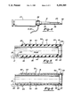
- FIG. 4 is a perspective view illustrating cannulation apparatus in accordance with the present invention.
- FIG. 5 is a longitudinal cross-sectional view of an embodiment of the ultrasonic flow sensing assembly of the present invention.
- FIG. 6 is a longitudinal cross-sectional view of an another embodiment of the ultrasonic flow sensing assembly of the present invention.
- FIG. 2 a schematic illustration of a syringe assembly is shown generally at 20 which includes needle 21 and a container portion or syringe 22 with ultrasonic transducer means 23 within needle 21 as will be described herein below.
- Wire conductors 24 are electrically connected with the transducer means 23 for the transmission and reception of electrical signals.
- needle 21 is inserted through tissue 25 toward blood vessel 26.
- the piezoelectric transducer containing assembly 23 is employed to more accurately direct the needle 21 to vessel 26 and facilitate its penetration.
- the sharpened distal tip of the needle is moved transversely, e.g. in a slight arc, for directing ultrasound energy transmitted through the needle to the vessel 26.
- the return or echo signal received by the transducer 23 is used for accurately guiding the needle 21 to the vessel 26 and provides an indication of when the needle penetrates vessel.
- FIG. 3 is a plot of intensity of the Doppler signal versus depth within tissue 25.
- the response is small and relatively flat as indicated.
- an increased generally uniform signal is detected.
- the intensity of the reflected wave increases and upon penetration of the vessel a stepped increase in the intensity of the reflected signal is indicated.
- Actual penetration of the vessel will be further indicated by the back flow of blood when the vessel is penetrated by maintaining a negative pressure in the needle by pulling back the syringe plunger while the needle is being advanced.
- a plot of intensity of the Doppler or reflected signal verses depth within the tissue with respect to the advancement toward an artery and the penetration thereof is similar to FIG.
- a brisk back flow of blood in the needle indicates safe penetration of the vessel and can cause a stepped increase in reflected wave intensity thereby indicating a safe location for injection of medications or for the safe passage of an introducer shaft or a guidewire into the vessel.
- FIG. 4 is a perspective view of apparatus for the cannulation of blood vessels in accordance with the present invention.
- the apparatus includes a needle portion 21, shown in sectioned view to illustrate the ultrasonic assembly 23 therein.
- the needle 21 and assembly 23 are connected to syringe 27 by means of connector 28.
- Electrical wires 30 and 31 are interconnected through the assembly with an ultrasonic transducer 23 at one end thereof.
- Transducer 23 is positioned at a sharpened distal end 32 of needle 21 for the transmission and reception of ultrasonic energy through the open end of the needle.
- the present invention employs an ultrasonic flow sensing assembly 34 as shown in FIG. 5 which incudes an elongated electric conducting inner tubular member 35 characterized by having a longitudinal axis 36, a distal end 37 and an inner lumen 38 extending therein.
- the ultrasonic flow sensing assembly 34 also includes an elongated electrically conducting over tubular member 40 which has a distal end 41, an inner lumen 43, and a longitudinal axis 42 coincident with the longitudinal axis 36 of the inner tubular member.
- Elongated electrically conductive outer tubular member 40 is separated from the inner tubular member 35 by the thickness of insulating means 44 which is preferably an insulating tube formed of a polyimide.
- the inner tubular member 35 can be formed of stainless steel.
- the outer tubular member 40 of this embodiment is a layer of conductive material, such as gold, on the exterior of the insulating polyimide tube 44.
- Piezoelectric transducer means 23 is capable of generating and receiving ultrasonic waves and is located at the distal ends 37 and 43 of inner and outer tubular members 35 and 40, respectively, and is electrically connected to the tubular members as shown. As a preferred embodiment, piezoelectric means 23 can be connected to tubular member 35 by an electrical conducting silver epoxy 45.
- the inner lumen 38 of the inner tubular member 35 is closed by the transducer 23 which is secured to the distal end thereof.
- the closed inner lumen 38 forms a chamber behind the transducer which is filled with air or other gas and which greatly enhances the sensitivity of the transducer 23.
- Electrical conductors 30 and 31 are shown in FIG. 5 connected to inner and outer tubular members 35 and 40, respectively.
- Conductor 30 is joined to the inner conductive tubular member 35 by means of a solder joint 46, whereas conductor 31 is connected to outer tube 40 via tungsten bands 47 and solder joint 48.
- An electrical coating 49 i.e. gold, is provided on the exterior of the transducer 23 to electrically connect the outer tubular member 40 with the transducer.
- the entire assembly 34 shown in FIG. 5 can be placed within needle 21 as shown schematically in FIG. 4 for cannulation of blood vessels which can be utilized for the carrying out of a Seldinger technique.
- the blood vessel penetration is indicated by the back flow of blood through the needle past assembly 34.
- assembly 34 can be removed from the needle 21 and a guidewire can be placed through the needle into the blood vessel and the needle itself then removed. Finally, prothesis can be guided into position in the blood vessel over the guidewire.
- FIG. 6 illustrates another preferred embodiment of an ultrasonic flow sensing assembly 50 in accordance with the invention.
- the assembly 50 includes an outer, electrically conductive tubular member 51 having a distal end 52 and an inner lumen 53 extending within the outer tubular member, and an inner, electrically conductive tubular member 54 having a distal end 55 and an inner lumen 56 extending within the inner tubular member.
- a piezoelectric transducer 57 is adjacent proximate and electrically connected to the distal ends 52 and 55 of the tubular members 51 and 54 respectively.
- An electrically insulating tubular member 58 is disposed between the outer and inner tubular members 51 and 54.
- An electrically conductive coating or layer 59 is provided on the exterior of the piezoelectric transducer 57 which extends to and electrically contacts the distal end 52 of the outer tubular member 51.
- An electrically conductive adhesive 60 bonds and electrically connects the distal end of the inner tubular member 54 to the backside of the piezoelectric transducer 57.
- Conductors 61 and 62 are secured to the proximal ends of the inner and outer tubular members 51 and 54 respectively by suitable means such as solder 63 and 64.
- the proximal end 65 of the outer conductive tubular member 51 is disposed a short distance from the distal end of the inner conductive tubular member 54 to provide access to the inner tubular member in order to join the conductor 66 to the inner tubular member by means of solder 63.
- the operation of the ultrasonic flow sensing assembly 50 of this embodiment is essentially the same as the operation of the previously described assembly as shown in FIGS. 2-5.
- the components which form the assembly 50 include an outer tubular member 51 with an OD of about 0.038 inch (0.965 mm) and an ID of about 0.034 inch (0.864 mm).
- the insulating tube 58 has an OD of about 0.034 inch (0.864 mm) and ID of about 0.03 inch (0.76 mm).
- the inner conducting tubular member 54 has an OD of about 0.03 inch (0.76 mm) and an ID of about 0.20 inch (0.51 m ).
- the overall length of assembly 50 is about 3.75 inches (9.53 cm)
- the inner and outer electrically conductive tubular members 51 and 54 may be made of stainless steel and the inner insulative tubular member 58 may be formed of polyimide. Other conducting and insulating materials may also be employed.
- the transverse cross sectional shape of the ultrasonic flow sensing assembly is circular to ready fit within the inner lumen of a needle and is dimensioned to leave a space between the outer surface of the assembly and the inner surface of the needle so that blood may readily flow there between.
- blood will flow through the annular area between the assembly and the needle when a vacuum is pulled by the syringe (not shown) which is releasably secured to the proximal end of the needle.
- the ultrasonic transducer is preferably formed of a lead zirconium titanate ceramic material which is sold by the Vernitron Company of Bedford, Ohio. It is sold by the designation 5H. Ceramic materials 5A is also suitable.
Abstract
Description
Claims (14)
Priority Applications (5)
| Application Number | Priority Date | Filing Date | Title |
|---|---|---|---|
| US07/813,123 US5259385A (en) | 1991-12-23 | 1991-12-23 | Apparatus for the cannulation of blood vessels |
| EP92121687A EP0548872B1 (en) | 1991-12-23 | 1992-12-21 | Ultrasonic flow sensing assembly |
| CA002085912A CA2085912C (en) | 1991-12-23 | 1992-12-21 | Apparatus for the cannulation of blood vessels |
| DE69220560T DE69220560T2 (en) | 1991-12-23 | 1992-12-21 | Ultrasonic flow meter |
| JP34259492A JP3732527B2 (en) | 1991-12-23 | 1992-12-22 | Ultrasound vascular flow sensing device and cannula insertion device |
Applications Claiming Priority (1)
| Application Number | Priority Date | Filing Date | Title |
|---|---|---|---|
| US07/813,123 US5259385A (en) | 1991-12-23 | 1991-12-23 | Apparatus for the cannulation of blood vessels |
Publications (1)
| Publication Number | Publication Date |
|---|---|
| US5259385A true US5259385A (en) | 1993-11-09 |
Family
ID=25211509
Family Applications (1)
| Application Number | Title | Priority Date | Filing Date |
|---|---|---|---|
| US07/813,123 Expired - Lifetime US5259385A (en) | 1991-12-23 | 1991-12-23 | Apparatus for the cannulation of blood vessels |
Country Status (5)
| Country | Link |
|---|---|
| US (1) | US5259385A (en) |
| EP (1) | EP0548872B1 (en) |
| JP (1) | JP3732527B2 (en) |
| CA (1) | CA2085912C (en) |
| DE (1) | DE69220560T2 (en) |
Cited By (33)
| Publication number | Priority date | Publication date | Assignee | Title |
|---|---|---|---|---|
| US5385148A (en) * | 1993-07-30 | 1995-01-31 | The Regents Of The University Of California | Cardiac imaging and ablation catheter |
| US5484416A (en) * | 1993-08-05 | 1996-01-16 | Advanced Cardiovascular Systems, Inc. | Coaxial cable vascular access system for use in various needles |
| WO1997017105A1 (en) * | 1995-11-09 | 1997-05-15 | Femrx, Inc. | Needle myolysis system for uterine fibroids |
| US5690115A (en) * | 1995-09-21 | 1997-11-25 | Feldman; Charles L. | Detecting vascular stenosis in chronic hemodialysis patients |
| US6312402B1 (en) * | 1998-09-24 | 2001-11-06 | Ekos Corporation | Ultrasound catheter for improving blood flow to the heart |
| US20030195426A1 (en) * | 1997-09-29 | 2003-10-16 | Boston Scientific Corporation | Ultrasound imaging guidewire with static central core and tip |
| US20060106315A1 (en) * | 2004-11-17 | 2006-05-18 | Roger Edens | Guided hypodermic cannula |
| US20070043290A1 (en) * | 2005-08-03 | 2007-02-22 | Goepp Julius G | Method and apparatus for the detection of a bone fracture |
| US20070129628A1 (en) * | 2005-12-02 | 2007-06-07 | The Cooper Health System | Regional anesthetic method and apparatus |
| US20070167829A1 (en) * | 2005-12-02 | 2007-07-19 | Robert Hirsh | Regional anesthetic method and apparatus |
| US7393330B2 (en) | 1999-08-05 | 2008-07-01 | Broncus Technologies, Inc. | Electrosurgical device having hollow tissue cutting member and transducer assembly |
| US7422563B2 (en) | 1999-08-05 | 2008-09-09 | Broncus Technologies, Inc. | Multifunctional tip catheter for applying energy to tissue and detecting the presence of blood flow |
| US7462162B2 (en) | 2001-09-04 | 2008-12-09 | Broncus Technologies, Inc. | Antiproliferative devices for maintaining patency of surgically created channels in a body organ |
| US7708712B2 (en) | 2001-09-04 | 2010-05-04 | Broncus Technologies, Inc. | Methods and devices for maintaining patency of surgically created channels in a body organ |
| US7883031B2 (en) | 2003-05-20 | 2011-02-08 | James F. Collins, Jr. | Ophthalmic drug delivery system |
| US20110106052A1 (en) * | 2009-10-30 | 2011-05-05 | Huihua Kenny Chiang | Ultrasonic positioning device for epidural space and method using the same |
| US8012136B2 (en) | 2003-05-20 | 2011-09-06 | Optimyst Systems, Inc. | Ophthalmic fluid delivery device and method of operation |
| US8265110B2 (en) | 2001-01-30 | 2012-09-11 | Board Of Trustees Operating Michigan State University | Laser and environmental monitoring method |
| US8409167B2 (en) | 2004-07-19 | 2013-04-02 | Broncus Medical Inc | Devices for delivering substances through an extra-anatomic opening created in an airway |
| US8627897B2 (en) | 2008-09-03 | 2014-01-14 | Black & Decker Inc. | Tiller housing |
| US8684980B2 (en) | 2010-07-15 | 2014-04-01 | Corinthian Ophthalmic, Inc. | Drop generating device |
| US8709034B2 (en) | 2011-05-13 | 2014-04-29 | Broncus Medical Inc. | Methods and devices for diagnosing, monitoring, or treating medical conditions through an opening through an airway wall |
| US8733935B2 (en) | 2010-07-15 | 2014-05-27 | Corinthian Ophthalmic, Inc. | Method and system for performing remote treatment and monitoring |
| WO2014093374A1 (en) * | 2012-12-13 | 2014-06-19 | Volcano Corporation | Devices, systems, and methods for targeted cannulation |
| US9087145B2 (en) | 2010-07-15 | 2015-07-21 | Eyenovia, Inc. | Ophthalmic drug delivery |
| US9345532B2 (en) | 2011-05-13 | 2016-05-24 | Broncus Medical Inc. | Methods and devices for ablation of tissue |
| US9533128B2 (en) | 2003-07-18 | 2017-01-03 | Broncus Medical Inc. | Devices for maintaining patency of surgically created channels in tissue |
| US10154923B2 (en) | 2010-07-15 | 2018-12-18 | Eyenovia, Inc. | Drop generating device |
| US10272260B2 (en) | 2011-11-23 | 2019-04-30 | Broncus Medical Inc. | Methods and devices for diagnosing, monitoring, or treating medical conditions through an opening through an airway wall |
| US10639194B2 (en) | 2011-12-12 | 2020-05-05 | Eyenovia, Inc. | High modulus polymeric ejector mechanism, ejector device, and methods of use |
| CN113786534A (en) * | 2021-11-15 | 2021-12-14 | 山东科锐医疗用品有限公司 | Ultrasonic measuring device for insulin injection pen needle |
| US11832877B2 (en) | 2017-04-03 | 2023-12-05 | Broncus Medical Inc. | Electrosurgical access sheath |
| US11938056B2 (en) | 2017-06-10 | 2024-03-26 | Eyenovia, Inc. | Methods and devices for handling a fluid and delivering the fluid to the eye |
Families Citing this family (6)
| Publication number | Priority date | Publication date | Assignee | Title |
|---|---|---|---|---|
| US5450853A (en) * | 1993-10-22 | 1995-09-19 | Scimed Life Systems, Inc. | Pressure sensor |
| US6537817B1 (en) | 1993-05-31 | 2003-03-25 | Packard Instrument Company | Piezoelectric-drop-on-demand technology |
| US6203759B1 (en) | 1996-05-31 | 2001-03-20 | Packard Instrument Company | Microvolume liquid handling system |
| US6521187B1 (en) | 1996-05-31 | 2003-02-18 | Packard Instrument Company | Dispensing liquid drops onto porous brittle substrates |
| JP4064205B2 (en) | 2002-10-23 | 2008-03-19 | 学校法人東海大学 | Puncture difficulty evaluation device |
| DE602004004995T2 (en) * | 2004-01-07 | 2007-11-22 | Universite Pierre Et Marie Curie | Trocar device for the passage of a surgical instrument |
Citations (7)
| Publication number | Priority date | Publication date | Assignee | Title |
|---|---|---|---|---|
| US4354500A (en) * | 1979-08-28 | 1982-10-19 | Univ Washington | System using ultrasonic energy for detection and quantification of air emboli |
| US4582067A (en) * | 1983-02-14 | 1986-04-15 | Washington Research Foundation | Method for endoscopic blood flow detection by the use of ultrasonic energy |
| US4665925A (en) * | 1985-09-13 | 1987-05-19 | Pfizer Hospital Products Group, Inc. | Doppler catheter |
| US4887606A (en) * | 1986-09-18 | 1989-12-19 | Yock Paul G | Apparatus for use in cannulation of blood vessels |
| US4991588A (en) * | 1986-07-21 | 1991-02-12 | Pfizer Hospital Products Group, Inc. | Doppler guide wire |
| US5070882A (en) * | 1988-03-28 | 1991-12-10 | Telectronics Pacing Systems, Inc. | Probe tip ultrasonic transducers and method of manufacture |
| US5109861A (en) * | 1989-04-28 | 1992-05-05 | Thomas Jefferson University | Intravascular, ultrasonic imaging catheters and methods for making same |
Family Cites Families (6)
| Publication number | Priority date | Publication date | Assignee | Title |
|---|---|---|---|---|
| US3556079A (en) * | 1967-05-16 | 1971-01-19 | Haruo Omizo | Method of puncturing a medical instrument under guidance of ultrasound |
| JPS5936A (en) * | 1982-06-24 | 1984-01-05 | オリンパス光学工業株式会社 | Flexible tube of endoscope |
| GB2157828B (en) * | 1984-04-19 | 1987-03-04 | Jan Lesny | Ultrasonic imaging apparatus and surgical instrument |
| DE3789477T2 (en) * | 1986-09-18 | 1994-07-14 | Paul G Yock | Device for use in drains of blood vessels. |
| US4899757A (en) * | 1988-02-22 | 1990-02-13 | Intertherapy, Inc. | Ultrasound imaging probe with zero dead space |
| GB8928533D0 (en) * | 1989-12-18 | 1990-02-21 | Lesny Jan | Ultrasonic instrument |
-
1991
- 1991-12-23 US US07/813,123 patent/US5259385A/en not_active Expired - Lifetime
-
1992
- 1992-12-21 CA CA002085912A patent/CA2085912C/en not_active Expired - Fee Related
- 1992-12-21 DE DE69220560T patent/DE69220560T2/en not_active Expired - Lifetime
- 1992-12-21 EP EP92121687A patent/EP0548872B1/en not_active Expired - Lifetime
- 1992-12-22 JP JP34259492A patent/JP3732527B2/en not_active Expired - Fee Related
Patent Citations (7)
| Publication number | Priority date | Publication date | Assignee | Title |
|---|---|---|---|---|
| US4354500A (en) * | 1979-08-28 | 1982-10-19 | Univ Washington | System using ultrasonic energy for detection and quantification of air emboli |
| US4582067A (en) * | 1983-02-14 | 1986-04-15 | Washington Research Foundation | Method for endoscopic blood flow detection by the use of ultrasonic energy |
| US4665925A (en) * | 1985-09-13 | 1987-05-19 | Pfizer Hospital Products Group, Inc. | Doppler catheter |
| US4991588A (en) * | 1986-07-21 | 1991-02-12 | Pfizer Hospital Products Group, Inc. | Doppler guide wire |
| US4887606A (en) * | 1986-09-18 | 1989-12-19 | Yock Paul G | Apparatus for use in cannulation of blood vessels |
| US5070882A (en) * | 1988-03-28 | 1991-12-10 | Telectronics Pacing Systems, Inc. | Probe tip ultrasonic transducers and method of manufacture |
| US5109861A (en) * | 1989-04-28 | 1992-05-05 | Thomas Jefferson University | Intravascular, ultrasonic imaging catheters and methods for making same |
Cited By (62)
| Publication number | Priority date | Publication date | Assignee | Title |
|---|---|---|---|---|
| US5385148A (en) * | 1993-07-30 | 1995-01-31 | The Regents Of The University Of California | Cardiac imaging and ablation catheter |
| US5484416A (en) * | 1993-08-05 | 1996-01-16 | Advanced Cardiovascular Systems, Inc. | Coaxial cable vascular access system for use in various needles |
| US5690115A (en) * | 1995-09-21 | 1997-11-25 | Feldman; Charles L. | Detecting vascular stenosis in chronic hemodialysis patients |
| WO1997017105A1 (en) * | 1995-11-09 | 1997-05-15 | Femrx, Inc. | Needle myolysis system for uterine fibroids |
| US5979453A (en) * | 1995-11-09 | 1999-11-09 | Femrx, Inc. | Needle myolysis system for uterine fibriods |
| US20040230123A1 (en) * | 1997-09-29 | 2004-11-18 | Boston Scientific Corporation | Ultrasound imaging guidewire with static central core and tip |
| US6770035B2 (en) * | 1997-09-29 | 2004-08-03 | Boston Scientific Corporation | Ultrasound imaging guidewire with static central core and tip |
| US20030195426A1 (en) * | 1997-09-29 | 2003-10-16 | Boston Scientific Corporation | Ultrasound imaging guidewire with static central core and tip |
| US7060033B2 (en) | 1997-09-29 | 2006-06-13 | Boston Scientific Corporation | Ultrasound imaging guidewire with static central core and tip |
| US6312402B1 (en) * | 1998-09-24 | 2001-11-06 | Ekos Corporation | Ultrasound catheter for improving blood flow to the heart |
| US7393330B2 (en) | 1999-08-05 | 2008-07-01 | Broncus Technologies, Inc. | Electrosurgical device having hollow tissue cutting member and transducer assembly |
| US7422563B2 (en) | 1999-08-05 | 2008-09-09 | Broncus Technologies, Inc. | Multifunctional tip catheter for applying energy to tissue and detecting the presence of blood flow |
| US8265110B2 (en) | 2001-01-30 | 2012-09-11 | Board Of Trustees Operating Michigan State University | Laser and environmental monitoring method |
| US7708712B2 (en) | 2001-09-04 | 2010-05-04 | Broncus Technologies, Inc. | Methods and devices for maintaining patency of surgically created channels in a body organ |
| US7462162B2 (en) | 2001-09-04 | 2008-12-09 | Broncus Technologies, Inc. | Antiproliferative devices for maintaining patency of surgically created channels in a body organ |
| US8936021B2 (en) | 2003-05-20 | 2015-01-20 | Optimyst Systems, Inc. | Ophthalmic fluid delivery system |
| US8545463B2 (en) | 2003-05-20 | 2013-10-01 | Optimyst Systems Inc. | Ophthalmic fluid reservoir assembly for use with an ophthalmic fluid delivery device |
| US8012136B2 (en) | 2003-05-20 | 2011-09-06 | Optimyst Systems, Inc. | Ophthalmic fluid delivery device and method of operation |
| US7883031B2 (en) | 2003-05-20 | 2011-02-08 | James F. Collins, Jr. | Ophthalmic drug delivery system |
| US9533128B2 (en) | 2003-07-18 | 2017-01-03 | Broncus Medical Inc. | Devices for maintaining patency of surgically created channels in tissue |
| US11357960B2 (en) | 2004-07-19 | 2022-06-14 | Broncus Medical Inc. | Devices for delivering substances through an extra-anatomic opening created in an airway |
| US8608724B2 (en) | 2004-07-19 | 2013-12-17 | Broncus Medical Inc. | Devices for delivering substances through an extra-anatomic opening created in an airway |
| US10369339B2 (en) | 2004-07-19 | 2019-08-06 | Broncus Medical Inc. | Devices for delivering substances through an extra-anatomic opening created in an airway |
| US8409167B2 (en) | 2004-07-19 | 2013-04-02 | Broncus Medical Inc | Devices for delivering substances through an extra-anatomic opening created in an airway |
| US8784400B2 (en) | 2004-07-19 | 2014-07-22 | Broncus Medical Inc. | Devices for delivering substances through an extra-anatomic opening created in an airway |
| US20060106315A1 (en) * | 2004-11-17 | 2006-05-18 | Roger Edens | Guided hypodermic cannula |
| WO2006055529A3 (en) * | 2004-11-17 | 2006-12-14 | Escalon Medical Corp | Guided hypodermic cannula |
| US20070043290A1 (en) * | 2005-08-03 | 2007-02-22 | Goepp Julius G | Method and apparatus for the detection of a bone fracture |
| US7931594B2 (en) * | 2005-12-02 | 2011-04-26 | The Cooper Health System | Regional anesthetic method and apparatus |
| US7645238B2 (en) * | 2005-12-02 | 2010-01-12 | The Cooper Health System | Regional anesthetic method and apparatus |
| US20070167829A1 (en) * | 2005-12-02 | 2007-07-19 | Robert Hirsh | Regional anesthetic method and apparatus |
| US20070129628A1 (en) * | 2005-12-02 | 2007-06-07 | The Cooper Health System | Regional anesthetic method and apparatus |
| US9913969B2 (en) | 2006-10-05 | 2018-03-13 | Broncus Medical Inc. | Devices for delivering substances through an extra-anatomic opening created in an airway |
| US8627897B2 (en) | 2008-09-03 | 2014-01-14 | Black & Decker Inc. | Tiller housing |
| US20110106052A1 (en) * | 2009-10-30 | 2011-05-05 | Huihua Kenny Chiang | Ultrasonic positioning device for epidural space and method using the same |
| US9480458B2 (en) | 2009-10-30 | 2016-11-01 | National Yang-Ming University | Ultrasonic positioning device for epidural space and method using the same |
| US8733935B2 (en) | 2010-07-15 | 2014-05-27 | Corinthian Ophthalmic, Inc. | Method and system for performing remote treatment and monitoring |
| US10073949B2 (en) | 2010-07-15 | 2018-09-11 | Eyenovia, Inc. | Ophthalmic drug delivery |
| US11011270B2 (en) | 2010-07-15 | 2021-05-18 | Eyenovia, Inc. | Drop generating device |
| US10839960B2 (en) | 2010-07-15 | 2020-11-17 | Eyenovia, Inc. | Ophthalmic drug delivery |
| US11398306B2 (en) | 2010-07-15 | 2022-07-26 | Eyenovia, Inc. | Ophthalmic drug delivery |
| US8684980B2 (en) | 2010-07-15 | 2014-04-01 | Corinthian Ophthalmic, Inc. | Drop generating device |
| US11839487B2 (en) | 2010-07-15 | 2023-12-12 | Eyenovia, Inc. | Ophthalmic drug delivery |
| US9087145B2 (en) | 2010-07-15 | 2015-07-21 | Eyenovia, Inc. | Ophthalmic drug delivery |
| US10154923B2 (en) | 2010-07-15 | 2018-12-18 | Eyenovia, Inc. | Drop generating device |
| US9486229B2 (en) | 2011-05-13 | 2016-11-08 | Broncus Medical Inc. | Methods and devices for excision of tissue |
| US9993306B2 (en) | 2011-05-13 | 2018-06-12 | Broncus Medical Inc. | Methods and devices for diagnosing, monitoring, or treating medical conditions through an opening through an airway wall |
| US8932316B2 (en) | 2011-05-13 | 2015-01-13 | Broncus Medical Inc. | Methods and devices for diagnosing, monitoring, or treating medical conditions through an opening through an airway wall |
| US8709034B2 (en) | 2011-05-13 | 2014-04-29 | Broncus Medical Inc. | Methods and devices for diagnosing, monitoring, or treating medical conditions through an opening through an airway wall |
| US10631938B2 (en) | 2011-05-13 | 2020-04-28 | Broncus Medical Inc. | Methods and devices for diagnosing, monitoring, or treating medical conditions through an opening through an airway wall |
| US9421070B2 (en) | 2011-05-13 | 2016-08-23 | Broncus Medical Inc. | Methods and devices for diagnosing, monitoring, or treating medical conditions through an opening through an airway wall |
| US9345532B2 (en) | 2011-05-13 | 2016-05-24 | Broncus Medical Inc. | Methods and devices for ablation of tissue |
| US10272260B2 (en) | 2011-11-23 | 2019-04-30 | Broncus Medical Inc. | Methods and devices for diagnosing, monitoring, or treating medical conditions through an opening through an airway wall |
| US10639194B2 (en) | 2011-12-12 | 2020-05-05 | Eyenovia, Inc. | High modulus polymeric ejector mechanism, ejector device, and methods of use |
| US10646373B2 (en) | 2011-12-12 | 2020-05-12 | Eyenovia, Inc. | Ejector mechanism, ejector device, and methods of use |
| WO2014093374A1 (en) * | 2012-12-13 | 2014-06-19 | Volcano Corporation | Devices, systems, and methods for targeted cannulation |
| US10238367B2 (en) * | 2012-12-13 | 2019-03-26 | Volcano Corporation | Devices, systems, and methods for targeted cannulation |
| US20140171788A1 (en) * | 2012-12-13 | 2014-06-19 | Volcano Corporation | Devices, Systems, and Methods for Targeted Cannulation |
| US11832877B2 (en) | 2017-04-03 | 2023-12-05 | Broncus Medical Inc. | Electrosurgical access sheath |
| US11938056B2 (en) | 2017-06-10 | 2024-03-26 | Eyenovia, Inc. | Methods and devices for handling a fluid and delivering the fluid to the eye |
| CN113786534B (en) * | 2021-11-15 | 2022-02-11 | 山东科锐医疗用品有限公司 | Ultrasonic measuring device for insulin injection pen needle |
| CN113786534A (en) * | 2021-11-15 | 2021-12-14 | 山东科锐医疗用品有限公司 | Ultrasonic measuring device for insulin injection pen needle |
Also Published As
| Publication number | Publication date |
|---|---|
| DE69220560T2 (en) | 1997-12-18 |
| CA2085912A1 (en) | 1993-06-24 |
| EP0548872A1 (en) | 1993-06-30 |
| JP3732527B2 (en) | 2006-01-05 |
| DE69220560D1 (en) | 1997-07-31 |
| JPH07184998A (en) | 1995-07-25 |
| CA2085912C (en) | 2004-02-24 |
| EP0548872B1 (en) | 1997-06-25 |
Similar Documents
| Publication | Publication Date | Title |
|---|---|---|
| US5259385A (en) | Apparatus for the cannulation of blood vessels | |
| US4887606A (en) | Apparatus for use in cannulation of blood vessels | |
| US5885219A (en) | Interrogation device and method | |
| US4856529A (en) | Ultrasonic pulmonary artery catheter and method | |
| US5968085A (en) | Pacing lead with integral guidance using ultrasound | |
| EP0260953B1 (en) | Device for use in the cannulation of blood vessels | |
| EP0712294B1 (en) | Coaxial cable vascular access system | |
| JP4541424B2 (en) | Therapeutic and diagnostic drug injection catheters | |
| US4541433A (en) | Cardiac output monitor | |
| US4911170A (en) | High frequency focused ultrasonic transducer for invasive tissue characterization | |
| US6165164A (en) | Catheter for injecting therapeutic and diagnostic agents | |
| US7179249B2 (en) | Directional needle injection drug delivery device and method of use | |
| US20060106315A1 (en) | Guided hypodermic cannula | |
| EP2338553A1 (en) | Echogenic needle catheter configured to produce an improved ultrasound image | |
| US20040143261A1 (en) | Surgical device with pressure monitoring ability | |
| CA2221620A1 (en) | High resolution intravascular signal detection | |
| JP2014050727A (en) | Method and apparatus for guiding and positioning intravascular device | |
| US6520916B1 (en) | Ultrasound imaging system and method for implantable and invasive devices | |
| JP2001178828A (en) | Injection catheter | |
| EP0190719A2 (en) | Puncturing apparatus | |
| CN219680715U (en) | Intracavity recanalization device integrating ultrasonic and acoustic impedance detection | |
| CN219271069U (en) | Pliers type bending-adjustable ultrasonic guide venipuncture system |
Legal Events
| Date | Code | Title | Description |
|---|---|---|---|
| AS | Assignment |
Owner name: ADVANCED CARDIOVASCULAR SYSTEMS, INC., CALIFORNIA Free format text: ASSIGNMENT OF ASSIGNORS INTEREST.;ASSIGNORS:MILLER, CHRISTOPHER;SHARKAWY, AHMED;REEL/FRAME:006184/0851;SIGNING DATES FROM 19920427 TO 19920506 |
|
| STCF | Information on status: patent grant |
Free format text: PATENTED CASE |
|
| AS | Assignment |
Owner name: CARDIOVASCULAR DYNAMICS, INC., CALIFORNIA Free format text: ASSIGNMENT OF ASSIGNORS INTEREST;ASSIGNOR:ADVANCED CARDIOVASCULAR SYSTEMS, INC.;REEL/FRAME:007991/0956 Effective date: 19960524 |
|
| FEPP | Fee payment procedure |
Free format text: PAT HOLDER CLAIMS SMALL ENTITY STATUS - SMALL BUSINESS (ORIGINAL EVENT CODE: SM02); ENTITY STATUS OF PATENT OWNER: SMALL ENTITY Free format text: PAYOR NUMBER ASSIGNED (ORIGINAL EVENT CODE: ASPN); ENTITY STATUS OF PATENT OWNER: SMALL ENTITY |
|
| FPAY | Fee payment |
Year of fee payment: 4 |
|
| AS | Assignment |
Owner name: RADIANCE MEDICAL SYSTEMS, INC., CALIFORNIA Free format text: CHANGE OF NAME;ASSIGNOR:CARDIOVASCULAR DYNAMICS, INC.;REEL/FRAME:009711/0243 Effective date: 19990114 |
|
| AS | Assignment |
Owner name: ESCALON VASCULAR ACCESS, INC., PENNSYLVANIA Free format text: ASSIGNMENT OF ASSIGNORS INTEREST;ASSIGNOR:RADIANCE MEDICAL SYSTEMS, INC., (FORMERLY CARDIOVASCULAR DYNAMICS, INC.);REEL/FRAME:009731/0257 Effective date: 19990121 |
|
| FPAY | Fee payment |
Year of fee payment: 8 |
|
| AS | Assignment |
Owner name: PNC BANK - NATIONAL ASSOCIATION, PENNSYLVANIA Free format text: RIDER TO SECURITY AGREEMENT;ASSIGNOR:ESCALON VASCULAR ACCESS, INC.;REEL/FRAME:012520/0552 Effective date: 20011116 |
|
| FPAY | Fee payment |
Year of fee payment: 12 |
|
| AS | Assignment |
Owner name: ESCALON VASCULAR IP HOLDINGS, INC., DELAWARE Free format text: ASSIGNMENT OF ASSIGNORS INTEREST;ASSIGNOR:ESCALON VASCULAR ACCESS, INC.;REEL/FRAME:019501/0033 Effective date: 20070628 |
|
| AS | Assignment |
Owner name: VASCULAR SOLUTIONS, INC., MINNESOTA Free format text: ASSIGNMENT OF ASSIGNORS INTEREST;ASSIGNOR:ESCALON VASCULAR IP HOLDING, INC.;REEL/FRAME:025026/0153 Effective date: 20100430 |