US5259752A - Insulation board for molding machine - Google Patents
Insulation board for molding machine Download PDFInfo
- Publication number
- US5259752A US5259752A US07/802,906 US80290691A US5259752A US 5259752 A US5259752 A US 5259752A US 80290691 A US80290691 A US 80290691A US 5259752 A US5259752 A US 5259752A
- Authority
- US
- United States
- Prior art keywords
- board
- grooves
- mold
- insulation board
- depth
- Prior art date
- Legal status (The legal status is an assumption and is not a legal conclusion. Google has not performed a legal analysis and makes no representation as to the accuracy of the status listed.)
- Expired - Fee Related
Links
Images
Classifications
-
- B—PERFORMING OPERATIONS; TRANSPORTING
- B29—WORKING OF PLASTICS; WORKING OF SUBSTANCES IN A PLASTIC STATE IN GENERAL
- B29C—SHAPING OR JOINING OF PLASTICS; SHAPING OF MATERIAL IN A PLASTIC STATE, NOT OTHERWISE PROVIDED FOR; AFTER-TREATMENT OF THE SHAPED PRODUCTS, e.g. REPAIRING
- B29C43/00—Compression moulding, i.e. applying external pressure to flow the moulding material; Apparatus therefor
- B29C43/32—Component parts, details or accessories; Auxiliary operations
-
- B—PERFORMING OPERATIONS; TRANSPORTING
- B30—PRESSES
- B30B—PRESSES IN GENERAL
- B30B15/00—Details of, or accessories for, presses; Auxiliary measures in connection with pressing
- B30B15/06—Platens or press rams
- B30B15/061—Cushion plates
-
- B—PERFORMING OPERATIONS; TRANSPORTING
- B29—WORKING OF PLASTICS; WORKING OF SUBSTANCES IN A PLASTIC STATE IN GENERAL
- B29L—INDEXING SCHEME ASSOCIATED WITH SUBCLASS B29C, RELATING TO PARTICULAR ARTICLES
- B29L2031/00—Other particular articles
- B29L2031/54—Balls
-
- Y—GENERAL TAGGING OF NEW TECHNOLOGICAL DEVELOPMENTS; GENERAL TAGGING OF CROSS-SECTIONAL TECHNOLOGIES SPANNING OVER SEVERAL SECTIONS OF THE IPC; TECHNICAL SUBJECTS COVERED BY FORMER USPC CROSS-REFERENCE ART COLLECTIONS [XRACs] AND DIGESTS
- Y10—TECHNICAL SUBJECTS COVERED BY FORMER USPC
- Y10T—TECHNICAL SUBJECTS COVERED BY FORMER US CLASSIFICATION
- Y10T428/00—Stock material or miscellaneous articles
- Y10T428/24—Structurally defined web or sheet [e.g., overall dimension, etc.]
- Y10T428/24479—Structurally defined web or sheet [e.g., overall dimension, etc.] including variation in thickness
- Y10T428/2457—Parallel ribs and/or grooves
Definitions
- the present invention relates to insulation board for molding machines and, in particular, relates to compression and injection molding operations wherein a plurality of molds, notably golf ball molds, are retained in a mold frame.
- the molding is accomplished in a mold assembly comprising a pair of opposed mold plates, each of which contains a plurality of individual golf ball half molds or mold cups within a mold frame.
- the mold frame has openings for receiving the individual molds.
- preformed golf ball cover half shells are placed about a golf ball core, the assembly is placed in the lower mold cups, the top mold cups joined to form the mold assembly, and the cover shells are subjected to sufficient heat and pressure so that they melt, knit together, form dimples and make the basic golf ball structure.
- the mold is then cooled so that it in turn cools the cover stock to solidify it before the mold is reopened.
- Standard compression molding techniques used today in the manufacture of golf balls have one or more channels running between adjacent rows of molds in the mold frame. Heating or cooling fluid as required is run through these channels in order to heat and cool the mold frame which in turn heats or cools the individual molds to change the temperature of the cover of the balls, see for example U.S. Pat. Nos. 4,508,309 and 4,757,972.
- the mold frames with their mold cups are generally set in a press which applies the pressure needed for the molding operation.
- the metal press has the ability to act as a huge "heat sink", exchanging heat with the mold frames and decreasing response time with respect to changing the temperature of the mold frames. If the press has not been insulated from the mold frames in any way, so much heat is transferred by the thermal medium used to heat up and cool down the mold frames that the operation becomes quite inefficient. This is especially true where high molding temperatures are required such as in the molding of Surlyn ionomer-covered golf balls.
- the applicant has now discovered that the out-of-planarity problem can be solved by the surprisingly simple solution of cutting grooves in the insulation board at various places. These grooves allow the insulation board to transmit the pressure of the press equally, without the variations that cause out-of-round distortions in products such as golf balls.
- the grooves are preferably cut so that they are orthogonal to each other.
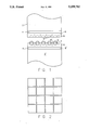
- FIG. 1 is a front elevation view of a molding press with the insulation board and the mold frame therein;
- FIG. 2 is a top view of the insulation board of the present invention showing a suitable layout for the grooves in the board.
- FIG. 1 shows the top and bottom platens 2, 2' of a hydraulic press (not shown). Insulation boards 4 are secured to both the top and bottom platens. Top and bottom mold plates 6, 6' with mold cups 8 and fluid channels 5 are secured to the platens 2, 2' with insulation boards 4 between the platen 2 and the top mold plate 6 and between the platen 2' and the bottom mold plate 6'.
- a golf ball core 7 is shown in one of the cups 8 with golf ball half shells 9, 9' above and below it respectively.
- FIG. 2 shows the insulation board 4 of the present invention with grooves 10 therein.
- the grooves may be of any dimension and laid out in any arrangement as long as they are sufficient for the insulation board to maintain its planarity to a sufficient degree for the article being molded and as long as the remaining insulation board is sufficient to support the mold without distortion.
- the squares formed by the intersecting grooves do not necessarily have to be the same size. However, it is preferred that all of the squares are the same size. The number of squares can vary. Good results on a 2 foot by 2 foot (0.6 m ⁇ 0.6 m) board have been found with one groove in a longitudinal direction and one in a latitudinal direction, making four squares. Better results have been found with two grooves in each of the longitudinal and latitudinal directions, making nine squares. Best results have been obtained with three grooves in each of the longitudinal and latitudinal directions, making sixteen squares.
- the depth of the grooves may also vary.
- the essential criterion is that the grooves must not be deep enough to destroy the structural integrity of the board for handling purposes. It is preferred that the grooves extend at least half-way through the board and it is more preferred that the grooves extend at least three-quarters of the way through the board.
- the width of the grooves may also vary.
- the width is suitably about 1/32" to 1/2" (0.08 cm to 1.3 cm) and it is preferred that the width be about 1/8" to 1/4" (0.3 cm to 0.6 cm).
- the grooves are suitably made using a conventional saw blade, however, any other suitable cutting device may also be used to form the grooves, such as a laser.
- the board may be made of any material suitable for the insulating and pressure purposes. Suitable materials are, for example, mineral wool, asbestos, cement board, glass fibers, or filled plastics. Applicant has found that a suitable material for the board is a glass fiber material in a thermosetting resin such as that marketed under the trade name Glasstherm.
- Applicant has used the board of the present invention for over 35 weeks and the problems that have plagued the applicant in the past have not occurred. There have been reduced numbers of out-of-round balls due to pressure variations in the molding operation and there has been no need to grind down the board to a proper degree of planarity.
Abstract
Description
Claims (8)
Priority Applications (2)
| Application Number | Priority Date | Filing Date | Title |
|---|---|---|---|
| US07/802,906 US5259752A (en) | 1990-10-05 | 1991-12-06 | Insulation board for molding machine |
| US08/106,166 US5368800A (en) | 1990-10-05 | 1993-08-13 | Method of molding objects within a molding machine having a grooved insulation board |
Applications Claiming Priority (2)
| Application Number | Priority Date | Filing Date | Title |
|---|---|---|---|
| US59312390A | 1990-10-05 | 1990-10-05 | |
| US07/802,906 US5259752A (en) | 1990-10-05 | 1991-12-06 | Insulation board for molding machine |
Related Parent Applications (1)
| Application Number | Title | Priority Date | Filing Date |
|---|---|---|---|
| US59312390A Continuation | 1990-10-05 | 1990-10-05 |
Related Child Applications (1)
| Application Number | Title | Priority Date | Filing Date |
|---|---|---|---|
| US08/106,166 Division US5368800A (en) | 1990-10-05 | 1993-08-13 | Method of molding objects within a molding machine having a grooved insulation board |
Publications (1)
| Publication Number | Publication Date |
|---|---|
| US5259752A true US5259752A (en) | 1993-11-09 |
Family
ID=27081628
Family Applications (2)
| Application Number | Title | Priority Date | Filing Date |
|---|---|---|---|
| US07/802,906 Expired - Fee Related US5259752A (en) | 1990-10-05 | 1991-12-06 | Insulation board for molding machine |
| US08/106,166 Expired - Fee Related US5368800A (en) | 1990-10-05 | 1993-08-13 | Method of molding objects within a molding machine having a grooved insulation board |
Family Applications After (1)
| Application Number | Title | Priority Date | Filing Date |
|---|---|---|---|
| US08/106,166 Expired - Fee Related US5368800A (en) | 1990-10-05 | 1993-08-13 | Method of molding objects within a molding machine having a grooved insulation board |
Country Status (1)
| Country | Link |
|---|---|
| US (2) | US5259752A (en) |
Cited By (8)
| Publication number | Priority date | Publication date | Assignee | Title |
|---|---|---|---|---|
| US5611269A (en) * | 1994-02-19 | 1997-03-18 | Maschinenfabrik J. Dieffenbacher Gmbh & Co. | Continuously operating press for the production of particle boards, fiber boards or similar wood boards and plastic boards |
| US5626886A (en) * | 1995-02-21 | 1997-05-06 | Dai-Ichi Seiko Co., Ltd. | Transfer molding machine for encapsulation of semiconductor devices |
| US5700496A (en) * | 1994-11-15 | 1997-12-23 | Bacon; Charles R. | Self-adjusting mold backplate |
| US5795596A (en) * | 1996-02-07 | 1998-08-18 | Acushnet Company | Compression mold with rubber shims |
| US6358031B1 (en) * | 1999-07-06 | 2002-03-19 | Sumitomo Rubber Industries, Ltd. | Golf ball-shaping mold and cavity die |
| US6494704B1 (en) | 2000-03-31 | 2002-12-17 | E. Khashoggi Industries, Llc | Mold apparatus |
| US20070042075A1 (en) * | 2005-08-22 | 2007-02-22 | Christopher Cavallaro | Fast thermal response mold |
| CN101722676A (en) * | 2008-10-01 | 2010-06-09 | 北川精机株式会社 | Pressing device |
Families Citing this family (4)
| Publication number | Priority date | Publication date | Assignee | Title |
|---|---|---|---|---|
| US6267761B1 (en) * | 1997-09-09 | 2001-07-31 | Sherwood Services Ag | Apparatus and method for sealing and cutting tissue |
| US6439873B1 (en) * | 2000-02-01 | 2002-08-27 | Callaway Golf Company | Golf ball casting mold assembly |
| US20050069600A1 (en) * | 2003-09-26 | 2005-03-31 | Scolamiero Stephen K. | Platen for improved molding |
| JP4455093B2 (en) | 2004-02-20 | 2010-04-21 | キヤノン株式会社 | Mold, processing apparatus using mold, and processing method using mold |
Citations (12)
| Publication number | Priority date | Publication date | Assignee | Title |
|---|---|---|---|---|
| US3016317A (en) * | 1957-06-21 | 1962-01-09 | Brunner Emil | Resilient mat |
| US3096545A (en) * | 1960-07-20 | 1963-07-09 | Rowland Products Inc | Resilient spacer for press-finishing of plastic sheet |
| US3387420A (en) * | 1967-02-15 | 1968-06-11 | Johns Manville | Ventilating covering element for built-up roofing |
| US3880561A (en) * | 1974-01-23 | 1975-04-29 | Richard A Ferro | Brassiere mold-forming machine |
| US4044984A (en) * | 1975-10-29 | 1977-08-30 | Hitachi, Ltd. | Mold assembly for resin-sealing |
| US4244761A (en) * | 1977-09-09 | 1981-01-13 | Societe Europeenne Des Produits Refractaires | Thermally insulating slabs made of refractory fibers for the insulation of furnaces and the like |
| US4465729A (en) * | 1981-08-05 | 1984-08-14 | Clopay Corporation | Cross-tearable plastic films |
| US4508309A (en) * | 1982-06-14 | 1985-04-02 | Acushnet Company | Fast thermal response mold |
| US4753160A (en) * | 1987-11-20 | 1988-06-28 | Motorola Inc. | Mold press force equalizer |
| US4757972A (en) * | 1986-08-29 | 1988-07-19 | Acushnet Company | Fast thermal response mold |
| US5069950A (en) * | 1990-04-11 | 1991-12-03 | Old Reliable Wholesale, Inc. | Insulated roof board |
| US5086639A (en) * | 1989-07-05 | 1992-02-11 | Wallman Lennert K O | Arrangement for carrying out pressing in eccentric presses |
-
1991
- 1991-12-06 US US07/802,906 patent/US5259752A/en not_active Expired - Fee Related
-
1993
- 1993-08-13 US US08/106,166 patent/US5368800A/en not_active Expired - Fee Related
Patent Citations (12)
| Publication number | Priority date | Publication date | Assignee | Title |
|---|---|---|---|---|
| US3016317A (en) * | 1957-06-21 | 1962-01-09 | Brunner Emil | Resilient mat |
| US3096545A (en) * | 1960-07-20 | 1963-07-09 | Rowland Products Inc | Resilient spacer for press-finishing of plastic sheet |
| US3387420A (en) * | 1967-02-15 | 1968-06-11 | Johns Manville | Ventilating covering element for built-up roofing |
| US3880561A (en) * | 1974-01-23 | 1975-04-29 | Richard A Ferro | Brassiere mold-forming machine |
| US4044984A (en) * | 1975-10-29 | 1977-08-30 | Hitachi, Ltd. | Mold assembly for resin-sealing |
| US4244761A (en) * | 1977-09-09 | 1981-01-13 | Societe Europeenne Des Produits Refractaires | Thermally insulating slabs made of refractory fibers for the insulation of furnaces and the like |
| US4465729A (en) * | 1981-08-05 | 1984-08-14 | Clopay Corporation | Cross-tearable plastic films |
| US4508309A (en) * | 1982-06-14 | 1985-04-02 | Acushnet Company | Fast thermal response mold |
| US4757972A (en) * | 1986-08-29 | 1988-07-19 | Acushnet Company | Fast thermal response mold |
| US4753160A (en) * | 1987-11-20 | 1988-06-28 | Motorola Inc. | Mold press force equalizer |
| US5086639A (en) * | 1989-07-05 | 1992-02-11 | Wallman Lennert K O | Arrangement for carrying out pressing in eccentric presses |
| US5069950A (en) * | 1990-04-11 | 1991-12-03 | Old Reliable Wholesale, Inc. | Insulated roof board |
Cited By (11)
| Publication number | Priority date | Publication date | Assignee | Title |
|---|---|---|---|---|
| US5611269A (en) * | 1994-02-19 | 1997-03-18 | Maschinenfabrik J. Dieffenbacher Gmbh & Co. | Continuously operating press for the production of particle boards, fiber boards or similar wood boards and plastic boards |
| CN1046657C (en) * | 1994-02-19 | 1999-11-24 | J·迪芬巴赫机器制造有限公司 | Pressing/heating plate of continous working pressing machine for producing wood bits plate or fibre plate etc. |
| US5700496A (en) * | 1994-11-15 | 1997-12-23 | Bacon; Charles R. | Self-adjusting mold backplate |
| US5626886A (en) * | 1995-02-21 | 1997-05-06 | Dai-Ichi Seiko Co., Ltd. | Transfer molding machine for encapsulation of semiconductor devices |
| US5795596A (en) * | 1996-02-07 | 1998-08-18 | Acushnet Company | Compression mold with rubber shims |
| US5935500A (en) * | 1996-02-07 | 1999-08-10 | Acushnet Company | Compression mold with rubber shims |
| US6358031B1 (en) * | 1999-07-06 | 2002-03-19 | Sumitomo Rubber Industries, Ltd. | Golf ball-shaping mold and cavity die |
| US6494704B1 (en) | 2000-03-31 | 2002-12-17 | E. Khashoggi Industries, Llc | Mold apparatus |
| US20070042075A1 (en) * | 2005-08-22 | 2007-02-22 | Christopher Cavallaro | Fast thermal response mold |
| CN101722676A (en) * | 2008-10-01 | 2010-06-09 | 北川精机株式会社 | Pressing device |
| CN101722676B (en) * | 2008-10-01 | 2013-08-21 | 北川精机株式会社 | Pressing device |
Also Published As
| Publication number | Publication date |
|---|---|
| US5368800A (en) | 1994-11-29 |
Similar Documents
| Publication | Publication Date | Title |
|---|---|---|
| US5259752A (en) | Insulation board for molding machine | |
| US4375350A (en) | Apparatus for forming elongated synthetic resin plate or sheet | |
| CA2400641A1 (en) | Building products | |
| DK0981280T4 (en) | A process for the manufacture of edible products | |
| GB2310162A (en) | Mould for resin transfer moulding | |
| AU647529B2 (en) | Improved insulation board for molding machine | |
| US3999917A (en) | Heat distribution and isolating mold support | |
| JPS6457630A (en) | Method and device for preventing warpage of semiconductor device | |
| JP3939860B2 (en) | Resin molding method | |
| KR100828182B1 (en) | Die with Three-Dimensional Heat Exchange Structure and Manufacturing Method thereof | |
| JPH0248911A (en) | Molding tool of ultra-high-molecular-weight polyethylene | |
| JP2827018B2 (en) | Method for producing porous sound absorbing material | |
| JPS63256415A (en) | Heating path device for plastic injection molding machine | |
| CN218015603U (en) | Built-in detachable quick cooling mould | |
| CN211307219U (en) | Steam quick-cooling and quick-heating die | |
| CN212045837U (en) | Uniform temperature type injection mold | |
| CN210450834U (en) | Mould with quick cooling effect | |
| JPS59145108A (en) | Press device | |
| JPH01178418A (en) | Compression molding | |
| JPS58208027A (en) | Multi-cylinder type injection molding machine | |
| CN207859478U (en) | A kind of film machine with embossing mechanism | |
| SU1263659A1 (en) | Centrifugal mould for producing kinescope cones | |
| CA2168267A1 (en) | Device for the production of mouldings and process for the production of such a device | |
| US3613174A (en) | Apparatus for producing molded printing plates | |
| JPS63252621A (en) | Method, die and center jig for forming diaphragm spring |
Legal Events
| Date | Code | Title | Description |
|---|---|---|---|
| FEPP | Fee payment procedure |
Free format text: PAYOR NUMBER ASSIGNED (ORIGINAL EVENT CODE: ASPN); ENTITY STATUS OF PATENT OWNER: LARGE ENTITY |
|
| FPAY | Fee payment |
Year of fee payment: 4 |
|
| FEPP | Fee payment procedure |
Free format text: PAT HLDR NO LONGER CLAIMS SMALL ENT STAT AS SMALL BUSINESS (ORIGINAL EVENT CODE: LSM2); ENTITY STATUS OF PATENT OWNER: LARGE ENTITY Free format text: PAT HOLDER CLAIMS SMALL ENTITY STATUS - SMALL BUSINESS (ORIGINAL EVENT CODE: SM02); ENTITY STATUS OF PATENT OWNER: LARGE ENTITY |
|
| FPAY | Fee payment |
Year of fee payment: 8 |
|
| REMI | Maintenance fee reminder mailed | ||
| REMI | Maintenance fee reminder mailed | ||
| LAPS | Lapse for failure to pay maintenance fees | ||
| STCH | Information on status: patent discontinuation |
Free format text: PATENT EXPIRED DUE TO NONPAYMENT OF MAINTENANCE FEES UNDER 37 CFR 1.362 |
|
| FP | Lapsed due to failure to pay maintenance fee |
Effective date: 20051109 |