US5270899A - Erasing apparatus - Google Patents

Erasing apparatus Download PDF

Info

Publication number
US5270899A
US5270899A US07/869,059 US86905992A US5270899A US 5270899 A US5270899 A US 5270899A US 86905992 A US86905992 A US 86905992A US 5270899 A US5270899 A US 5270899A
Authority
US
United States
Prior art keywords
erasing
magnetic tape
tape roll
positions
space
Prior art date
Legal status (The legal status is an assumption and is not a legal conclusion. Google has not performed a legal analysis and makes no representation as to the accuracy of the status listed.)
Expired - Fee Related
Application number
US07/869,059
Inventor
Yukio Saito
Current Assignee (The listed assignees may be inaccurate. Google has not performed a legal analysis and makes no representation or warranty as to the accuracy of the list.)
Sanix Corp
Original Assignee
Sanix Corp
Priority date (The priority date is an assumption and is not a legal conclusion. Google has not performed a legal analysis and makes no representation as to the accuracy of the date listed.)
Filing date
Publication date
Priority claimed from JP63287409A external-priority patent/JP2545451B2/en
Application filed by Sanix Corp filed Critical Sanix Corp
Priority to US07/869,059 priority Critical patent/US5270899A/en
Assigned to SANIX CORPORATION reassignment SANIX CORPORATION ASSIGNMENT OF ASSIGNORS INTEREST (SEE DOCUMENT FOR DETAILS). Assignors: SAITO, YUKIO
Application granted granted Critical
Publication of US5270899A publication Critical patent/US5270899A/en
Anticipated expiration legal-status Critical
Expired - Fee Related legal-status Critical Current

Links

Images

Classifications

    • GPHYSICS
    • G11INFORMATION STORAGE
    • G11BINFORMATION STORAGE BASED ON RELATIVE MOVEMENT BETWEEN RECORD CARRIER AND TRANSDUCER
    • G11B5/00Recording by magnetisation or demagnetisation of a record carrier; Reproducing by magnetic means; Record carriers therefor
    • G11B5/02Recording, reproducing, or erasing methods; Read, write or erase circuits therefor
    • G11B5/024Erasing
    • G11B5/0245Bulk erasing

Definitions

  • This invention relates to an erasing apparatus for erasing information recorded on an analog or digital magnetic tape wound into a roll.
  • Erasing apparatus of this type have already been employed.
  • conventional erasing apparatus have had serious disadvantages such as the use of a large-sized erasing coil as described later.
  • an erasing apparatus for erasing information recorded on a magnetic tape wound into a roll having a diameter.
  • the erasing apparatus comprises an erasing coil wound in the form of a solenoid defining a space therein.
  • the space has a width shorter than the diameter of the magnetic tape roll and a length longer than the diameter of the magnetic tape roll.
  • the apparatus also comprises means for moving the magnetic tape roll intermittently to different erasing positions in a predetermined sequence so that the magnetic tape roll has different portions placed in the space at the respective erasing positions.
  • a means is provided for producing a ringing signal to the erasing coil to provide a magnetic field in the space so as to perform one erasing operation cycle for erasing information recorded on the magnetic tape roll each time the magnetic tape roll is placed at one of the erasing positions.
  • FIG. 1 is a perspective view of a prior art erasing apparatus
  • FIG. 2 is an elevational view of the prior art erasing apparatus
  • FIG. 3 is a side view of the prior art erasing apparatus
  • FIG. 4 is a schematic diagram showing one embodiment of an erasing apparatus made in accordance with the invention.
  • FIG. 5 is a perspective view of the erasing section used in the erasing apparatus of FIG. 4;
  • FIG. 6 is a block diagram showing significant components used in the erasing apparatus of FIG. 4;
  • FIG. 7 is a graph showing the waveform of the ringing signal applied to the erasing coil
  • FIG. 8 is a plan view used in explaining the positions of the magnetic tape roll with respect to the erasing coil at respective erasing positions.
  • FIG. 9 is a plan view showing reference position marks provided on the slider used in the erasing apparatus of FIG. 4.
  • FIGS. 10A-10D illustrate a flow chart which indicates the logic in the control unit.
  • FIGS. 1 to 3 Prior to the description of the preferred embodiment of the present invention, the prior art erasing apparatus of FIGS. 1 to 3 is briefly described in order to provide a basis for a better understanding of the difficulties attendant therewith.
  • the prior art erasing apparatus includes an erasing coil 1 having a space 2 for receipt of a roll of magnetic tape 3 to be handled.
  • a ringing signal which has an envelope decreasing with the lapse of time, is applied to the erasing coil 1 to provide a desired magnetic field for erasing the information recorded on the magnetic tape 3 placed in the space 2. Since the erasing coil 1 has a maximum erasing efficiency for the information recorded on magnetic tape portions substantially in parallel with the magnetic flux, it is required to rotate the magnetic tape roll in a direction within the space 2 while applying the ringing signal to the erasing coil 1 in order to erase the information recorded on the entire area of the magnetic tape 3.
  • the erasing apparatus also includes a pair of rollers 4 for rotating the magnetic tape roll within the space 2. This type of erasing apparatus is disclosed in Japanese Patent Kokai No. 61-170904.
  • Such a conventional erasing apparatus employs a large-sized erasing coil wound to have a space sized large enough to receive the overall size of the magnetic tape roll.
  • the erasing coil has a great electric resistance and thus requires current of a great magnitude to provide a sufficient magnetic field for erasing the information recorded on the magnetic tape. This results in a space and power consuming erasing apparatus.
  • the erasing apparatus includes an erasing section 11 for erasing the information recorded on a roll of magnetic tape which may be wound around a reel or the like.
  • the erasing section 11 includes an erasing coil 12 wound in the form of a solenoid defining an elongated space 14 having a width much (for example, several times) shorter than the diameter of the magnetic tape roll and a length longer than the diameter of the magnetic tape roll so that the magnetic tape roll can move through the space 14.
  • a ringing signal is applied to the erasing coil 12 for producing a magnetic field in the space 14.
  • a pair of cores 13 having high permeability are optionally provided on the opposite sides of the erasing coil 12, as best shown in FIG. 5, for increasing the magnetic field intensity in the space 14.
  • the erasing apparatus also includes a slider 21 placed on a plurality of feed rollers 23.
  • the slider 21 is formed with a number of through-holes 26 arranged in a line.
  • the slider 21 is shown as carrying a magnetic tape roll 27 placed thereon at a predetermined position.
  • the numeral 22 designates a motor for driving one or more feed rollers 23 in a first direction moving the slider 21 toward the erasing section 11 and in a second direction moving the slider 21 away from the erasing section 11.
  • the position of the slider 21 with respect to its initial position is sensed by a position sensor 24.
  • the position sensor 24 may be of the type including an encoder for producing a series of pulses, the number of which corresponds to the displacement of the slider 21 from the initial position.
  • optical sensors 25 are located at positions just below the respective holes 26 when the slider 21 is placed at the initial position shown in FIG. 4.
  • Each of the optical sensors 25 includes a light emission element for emitting light toward the corresponding hole 26 and a light receipt element for producing a signal indicative of the intensity of the light incident thereon.
  • the light incident on the light receipt element has a great intensity when the corresponding hole 26 is closed by the magnetic tape roll 27 and a small intensity when the corresponding hole 26 is open.
  • the position sensor 24 and the optical sensors 25 are connected to a control unit 32 (see FIG. 6) which may employ a microcomputer.
  • the control unit 32 receives signals from the optical sensors 25 for detecting the diameter of the magnetic tape roll 27 placed on the slider 21.
  • the control unit 32 calculates a required number of erasing positions by dividing the detected, diameter of the magnetic tape roll 27 by the width of the space 14 of the erasing coil 12.
  • the control unit 32 determines the erasing positions based on the calculated erasing position number.
  • the control unit 32 produces a control signal to a motor drive circuit 33 which thereby controls the motor 22 in a manner to bring the magnetic tape roll 27 to the determined erasing positions in a predetermined sequence.
  • the control unit 32 senses these erasing positions based on the signal fed thereto from the position sensor 24.
  • the control unit 32 produces a control signal to a ringing signal generator 34 which thereby produces a ringing signal to the erasing coil 12 to provide a magnetic field in the space 14 of the erasing coil 12 so as to perform one cycle of erasing operation for erasing information recorded on the magnetic tape roll each time the magnetic tape roll 27 is placed at one of the erasing positions.
  • the ringing signal has an envelope decreasing with the lapse of time, as shown in FIG. 7.
  • the control unit 32 produces a control signal causing a display control circuit 35 to display a digit corresponding to the calculated erasing position number on a display unit 36.
  • the control unit 32 decreases the displayed digit each time one erasing operation cycle is completed as sensed by the position sensor 24 to indicate the number of the remaining erasing operation cycles.
  • the control unit 32 receives an additional input from an input device 31 having a push button pad provided with a number of push buttons for manually entering various kinds of information to the control unit 32.
  • the push buttons include numerical digit (0-9) push buttons and a start button.
  • the numerical digit push buttons are used in manually inputting a desired number of erasing positions. In this case, the optical sensors 25 may be removed.
  • the start button is depressed, the input device 31 produces a start command signal to the control unit 32 which thereby starts the erasing operation.
  • FIGS. 10A, 10B, 10C and 10D illustrate a flow chart which indicates the logic in the control unit 32.
  • the schematic flow chart indicates that the diameter of the tape roll 27 is detected or measured and that the number of erasing positions are calculated and displayed after the diameter has been detected and that the driving motor 22 is operated for movement of the tape roll to a first erasing position and then to subsequent erasing positions thus establishing that the tape roll 27 is moved intermittently as opposed to continuously.
  • the flow chart indicates that a ringing signal is produced after the tape roll 27 has reached a predetermined position and that the driving motor 22 is operated in a second direction subsequently to the ringing signal.
  • the flow chart also indicates that the calculated erasing position number is displayed and that the displayed digit decreases and indicates the repetitive production of a ringing signal, decreasing displayed digit and movement of the tape roll.
  • a magnetic tape roll 27 is placed at a predetermined position on the slider 21.
  • the control unit 32 detects the diameter of the magnetic tape roll 27 based on the signals fed thereto from the optical sensors 25.
  • the control unit 32 calculates a required number of (in the illustrated case three) erasing positions by dividing the detected magnetic tape roll diameter by the length of the space 14 of the erasing coil 12 and determines the erasing positions (in the illustrated case first, second and third erasing positions).
  • the control unit 32 produces a control signal causing the motor drive circuit 33 to drive the motor 22 in the first direction moving the slider 21 along with the magnetic tape roll 27 to the right, as viewed in FIG. 4.
  • the position sensor 24 When the slider 21 reaches the first erasing position, the position sensor 24 produces a signal to the control unit 32 which thereby produces a stop signal causing the motor drive circuit 33 to stop the motor 22.
  • the magnetic tape roll 27 has a first portion placed in the space 14 of the erasing coil 12, the first portion having a size equal to about one-third of the overall size of the magnetic tape roll 27, as shown in FIG. 8 where the phantom lines 12c indicate the position of the erasing coil 12 with respect to the magnetic tape roll 27 when the slider 21 is at the first erasing position.
  • the control unit 32 produces a control signal causing the ringing signal generator 34 to produce a ringing signal to the erasing coil 12.
  • the ringing signal may be produced a predetermined number of times.
  • the control unit 32 Upon completion of this first erasing operation cycle, the control unit 32 produces a control signal causing the motor drive circuit 33 to drive the motor 22 further in the first direction.
  • the position sensor 24 produces a signal to the control unit 32 which thereby produces a stop signal causing the motor drive circuit 33 to stop the motor 22.
  • the magnetic tape roll 27 has a second portion placed in the space 14 of the erasing coil 12. The second portion has a size equal to about one-third of the overall size of the magnetic tape roll 27, as shown in FIG. 8 where the solid lines 12a indicate the position of the erasing coil 12 with respect to the magnetic tape roll 27 when the slider 21 is at the second erasing position.
  • control unit 32 produces a control signal causing the ringing signal generator 34 to produce a ringing signal to the erasing coil 12.
  • a magnetic field is produced in the space 14 of the erasing coil 12 to erase the information recorded on the second portion of the magnetic tape roll 27.
  • the ringing signal may be produced a predetermined number of times.
  • the control unit 32 Upon completion of this second erasing operation cycle, the control unit 32 produces a control signal causing the motor drive circuit 33 to drive the motor 22 further in the first direction.
  • the position sensor 24 produces a signal to the control unit 32 which thereby produces a stop signal causing the motor drive circuit 33 to stop the motor 22.
  • the magnetic tape roll 27 has a third portion placed in the space 14 of the erasing coil 12. The third portion has a size equal to about one-third of the overall size of the magnetic tape roll 27, as shown in FIG. 8 where the phantom lines 12b indicate the position of the erasing coil 12 with respect to the magnetic tape roll 27 when the slider 21 is placed at the third erasing position.
  • control unit 32 produces a control signal causing the ringing signal generator 34 to produce a ringing signal to the erasing coil 12.
  • a magnetic field is produced in the space 14 of the erasing coil 12 to erase the information recorded on the third portion of the magnetic tape roll 27.
  • the ringing signal may be produced a predetermined number of times.
  • the control unit 32 Upon completion of this third erasing operation cycle, the control unit 32 produces a control signal causing the motor drive circuit 33 to drive the motor 22 in the second direction moving the slider 21 along with the magnetic tape roll 27 to the left, as viewed in FIG. 4.
  • the position sensor 24 produces a signal to the control unit 32 which thereby produces a stop signal causing the motor drive circuit 33 to stop the motor 22.
  • a maximum erasing efficiency is achieved when the direction of the magnetic field produced in the space 14 is in parallel with the direction in which the magnetic tape is magnetized to have information recorded thereon. Therefore, the erasing section 11 can erase the information recorded on the second portion of the magnetic tape roll 27 with higher efficiency as compared to the information recorded on the first and third portions thereof.
  • the recorded information can be erased to a sufficient extend if the force of the magnetic field produced in the space 14 has a magnitude overcoming the coercive force maintaining the information on the magnetic tape
  • the ringing signal may be produced at a predetermined number of times to the erasing coil 12 after the magnetic tape roll 27 is rotated manually at a predetermined angle upon completion of each of the erasing operation cycles.
  • marks 41 on the surface portion of the slider 21 on which the magnetic tape roll 27 is placed.
  • the marks 41 are shown in FIG. 9 as including three radially extending reference position lines 1, 2 and 3 which respectively indicates first, second and third positions at which first, second and third erasing operation cycles are to be made in this order. It is appreciated that the magnetic tape roll 27 may be rotated automatically at a predetermined angle upon completion of each of the erasing operation cycles.

Abstract

An apparatus for erasing information recorded on a magnetic tape wound into a roll having a diameter. The apparatus comprises an erasing coil wound in the form of a solenoid defining a space therein. The space has a width shorter than the diameter of the magnetic tape roll and a length longer than the diameter of the magnetic tape roll. The magnetic tape roll is moved intermittently to different erasing positions in a predetermined sequence so that the magnetic tape roll has different portions placed in the space at the respective erasing positions. A ringing signal is applied to the erasing coil to provide a magnetic field in the space for erasing information recorded on the magnetic tape roll each time the magnetic tape roll is placed at one of the erasing positions.

Description

This application is a continuation-in-part of application Ser. No. 07/435,760, filed Nov. 14, 1989 now abandoned.
BACKGROUND OF THE INVENTION
This invention relates to an erasing apparatus for erasing information recorded on an analog or digital magnetic tape wound into a roll.
Erasing apparatus of this type have already been employed. However, conventional erasing apparatus have had serious disadvantages such as the use of a large-sized erasing coil as described later.
SUMMARY OF THE INVENTION
Therefore, it is a main object of the invention to provide an improved erasing apparatus which can use a small-sized erasing coil consuming far less power.
There is provided, in accordance with the invention, an erasing apparatus for erasing information recorded on a magnetic tape wound into a roll having a diameter. The erasing apparatus comprises an erasing coil wound in the form of a solenoid defining a space therein. The space has a width shorter than the diameter of the magnetic tape roll and a length longer than the diameter of the magnetic tape roll. The apparatus also comprises means for moving the magnetic tape roll intermittently to different erasing positions in a predetermined sequence so that the magnetic tape roll has different portions placed in the space at the respective erasing positions. A means is provided for producing a ringing signal to the erasing coil to provide a magnetic field in the space so as to perform one erasing operation cycle for erasing information recorded on the magnetic tape roll each time the magnetic tape roll is placed at one of the erasing positions.
BRIEF DESCRIPTION OF THE DRAWINGS
This invention will be described in greater detail by reference to the following description taken in connection with the accompanying drawings in which:
FIG. 1 is a perspective view of a prior art erasing apparatus;
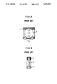
FIG. 2 is an elevational view of the prior art erasing apparatus;
FIG. 3 is a side view of the prior art erasing apparatus;
FIG. 4 is a schematic diagram showing one embodiment of an erasing apparatus made in accordance with the invention;
FIG. 5 is a perspective view of the erasing section used in the erasing apparatus of FIG. 4;
FIG. 6 is a block diagram showing significant components used in the erasing apparatus of FIG. 4;
FIG. 7 is a graph showing the waveform of the ringing signal applied to the erasing coil;
FIG. 8 is a plan view used in explaining the positions of the magnetic tape roll with respect to the erasing coil at respective erasing positions; and
FIG. 9 is a plan view showing reference position marks provided on the slider used in the erasing apparatus of FIG. 4.
FIGS. 10A-10D illustrate a flow chart which indicates the logic in the control unit.
DETAILED DESCRIPTION OF THE PREFERRED EMBODIMENT
Prior to the description of the preferred embodiment of the present invention, the prior art erasing apparatus of FIGS. 1 to 3 is briefly described in order to provide a basis for a better understanding of the difficulties attendant therewith.
The prior art erasing apparatus includes an erasing coil 1 having a space 2 for receipt of a roll of magnetic tape 3 to be handled. A ringing signal, which has an envelope decreasing with the lapse of time, is applied to the erasing coil 1 to provide a desired magnetic field for erasing the information recorded on the magnetic tape 3 placed in the space 2. Since the erasing coil 1 has a maximum erasing efficiency for the information recorded on magnetic tape portions substantially in parallel with the magnetic flux, it is required to rotate the magnetic tape roll in a direction within the space 2 while applying the ringing signal to the erasing coil 1 in order to erase the information recorded on the entire area of the magnetic tape 3. For this purpose, the erasing apparatus also includes a pair of rollers 4 for rotating the magnetic tape roll within the space 2. This type of erasing apparatus is disclosed in Japanese Patent Kokai No. 61-170904.
However, such a conventional erasing apparatus employs a large-sized erasing coil wound to have a space sized large enough to receive the overall size of the magnetic tape roll. The erasing coil has a great electric resistance and thus requires current of a great magnitude to provide a sufficient magnetic field for erasing the information recorded on the magnetic tape. This results in a space and power consuming erasing apparatus.
Referring to FIG. 4, there is illustrated an erasing apparatus embodying the invention. The erasing apparatus includes an erasing section 11 for erasing the information recorded on a roll of magnetic tape which may be wound around a reel or the like. The erasing section 11 includes an erasing coil 12 wound in the form of a solenoid defining an elongated space 14 having a width much (for example, several times) shorter than the diameter of the magnetic tape roll and a length longer than the diameter of the magnetic tape roll so that the magnetic tape roll can move through the space 14. A ringing signal is applied to the erasing coil 12 for producing a magnetic field in the space 14. A pair of cores 13 having high permeability are optionally provided on the opposite sides of the erasing coil 12, as best shown in FIG. 5, for increasing the magnetic field intensity in the space 14.
The erasing apparatus also includes a slider 21 placed on a plurality of feed rollers 23. The slider 21 is formed with a number of through-holes 26 arranged in a line. The slider 21 is shown as carrying a magnetic tape roll 27 placed thereon at a predetermined position. The numeral 22 designates a motor for driving one or more feed rollers 23 in a first direction moving the slider 21 toward the erasing section 11 and in a second direction moving the slider 21 away from the erasing section 11. The position of the slider 21 with respect to its initial position is sensed by a position sensor 24. The position sensor 24 may be of the type including an encoder for producing a series of pulses, the number of which corresponds to the displacement of the slider 21 from the initial position. In order to measure the diameter of the magnetic tape roll 27 placed on the slider 21, optical sensors 25 are located at positions just below the respective holes 26 when the slider 21 is placed at the initial position shown in FIG. 4. Each of the optical sensors 25 includes a light emission element for emitting light toward the corresponding hole 26 and a light receipt element for producing a signal indicative of the intensity of the light incident thereon. The light incident on the light receipt element has a great intensity when the corresponding hole 26 is closed by the magnetic tape roll 27 and a small intensity when the corresponding hole 26 is open. The position sensor 24 and the optical sensors 25 are connected to a control unit 32 (see FIG. 6) which may employ a microcomputer.
Referring to FIG. 6, the control unit 32 receives signals from the optical sensors 25 for detecting the diameter of the magnetic tape roll 27 placed on the slider 21. The control unit 32 calculates a required number of erasing positions by dividing the detected, diameter of the magnetic tape roll 27 by the width of the space 14 of the erasing coil 12. The control unit 32 determines the erasing positions based on the calculated erasing position number. The control unit 32 produces a control signal to a motor drive circuit 33 which thereby controls the motor 22 in a manner to bring the magnetic tape roll 27 to the determined erasing positions in a predetermined sequence. The control unit 32 senses these erasing positions based on the signal fed thereto from the position sensor 24. The control unit 32 produces a control signal to a ringing signal generator 34 which thereby produces a ringing signal to the erasing coil 12 to provide a magnetic field in the space 14 of the erasing coil 12 so as to perform one cycle of erasing operation for erasing information recorded on the magnetic tape roll each time the magnetic tape roll 27 is placed at one of the erasing positions. The ringing signal has an envelope decreasing with the lapse of time, as shown in FIG. 7. The control unit 32 produces a control signal causing a display control circuit 35 to display a digit corresponding to the calculated erasing position number on a display unit 36. The control unit 32 decreases the displayed digit each time one erasing operation cycle is completed as sensed by the position sensor 24 to indicate the number of the remaining erasing operation cycles.
The control unit 32 receives an additional input from an input device 31 having a push button pad provided with a number of push buttons for manually entering various kinds of information to the control unit 32. The push buttons include numerical digit (0-9) push buttons and a start button. The numerical digit push buttons are used in manually inputting a desired number of erasing positions. In this case, the optical sensors 25 may be removed. When the start button is depressed, the input device 31 produces a start command signal to the control unit 32 which thereby starts the erasing operation.
FIGS. 10A, 10B, 10C and 10D illustrate a flow chart which indicates the logic in the control unit 32. Specifically, the schematic flow chart indicates that the diameter of the tape roll 27 is detected or measured and that the number of erasing positions are calculated and displayed after the diameter has been detected and that the driving motor 22 is operated for movement of the tape roll to a first erasing position and then to subsequent erasing positions thus establishing that the tape roll 27 is moved intermittently as opposed to continuously. Further, the flow chart indicates that a ringing signal is produced after the tape roll 27 has reached a predetermined position and that the driving motor 22 is operated in a second direction subsequently to the ringing signal. The flow chart also indicates that the calculated erasing position number is displayed and that the displayed digit decreases and indicates the repetitive production of a ringing signal, decreasing displayed digit and movement of the tape roll.
The operation is as follows:
First of all, a magnetic tape roll 27 is placed at a predetermined position on the slider 21. The control unit 32 detects the diameter of the magnetic tape roll 27 based on the signals fed thereto from the optical sensors 25. The control unit 32 calculates a required number of (in the illustrated case three) erasing positions by dividing the detected magnetic tape roll diameter by the length of the space 14 of the erasing coil 12 and determines the erasing positions (in the illustrated case first, second and third erasing positions). When the operator depresses the start button to produce a start command signal from the input device 31, the control unit 32 produces a control signal causing the motor drive circuit 33 to drive the motor 22 in the first direction moving the slider 21 along with the magnetic tape roll 27 to the right, as viewed in FIG. 4. When the slider 21 reaches the first erasing position, the position sensor 24 produces a signal to the control unit 32 which thereby produces a stop signal causing the motor drive circuit 33 to stop the motor 22. At this first erasing position, the magnetic tape roll 27 has a first portion placed in the space 14 of the erasing coil 12, the first portion having a size equal to about one-third of the overall size of the magnetic tape roll 27, as shown in FIG. 8 where the phantom lines 12c indicate the position of the erasing coil 12 with respect to the magnetic tape roll 27 when the slider 21 is at the first erasing position. Following this, the control unit 32 produces a control signal causing the ringing signal generator 34 to produce a ringing signal to the erasing coil 12. As a result, a magnetic field is produced in the space 14 of the erasing coil 12 to erase the information recorded on the first portion of the magnetic tape roll 27. The ringing signal may be produced a predetermined number of times.
Upon completion of this first erasing operation cycle, the control unit 32 produces a control signal causing the motor drive circuit 33 to drive the motor 22 further in the first direction. When the slider 21 reaches the second erasing position, the position sensor 24 produces a signal to the control unit 32 which thereby produces a stop signal causing the motor drive circuit 33 to stop the motor 22. At this second erasing position, the magnetic tape roll 27 has a second portion placed in the space 14 of the erasing coil 12. The second portion has a size equal to about one-third of the overall size of the magnetic tape roll 27, as shown in FIG. 8 where the solid lines 12a indicate the position of the erasing coil 12 with respect to the magnetic tape roll 27 when the slider 21 is at the second erasing position. Following this, the control unit 32 produces a control signal causing the ringing signal generator 34 to produce a ringing signal to the erasing coil 12. As a result, a magnetic field is produced in the space 14 of the erasing coil 12 to erase the information recorded on the second portion of the magnetic tape roll 27. The ringing signal may be produced a predetermined number of times.
Upon completion of this second erasing operation cycle, the control unit 32 produces a control signal causing the motor drive circuit 33 to drive the motor 22 further in the first direction. When the slider 21 reaches the third erasing position, the position sensor 24 produces a signal to the control unit 32 which thereby produces a stop signal causing the motor drive circuit 33 to stop the motor 22. At this third erasing position, the magnetic tape roll 27 has a third portion placed in the space 14 of the erasing coil 12. The third portion has a size equal to about one-third of the overall size of the magnetic tape roll 27, as shown in FIG. 8 where the phantom lines 12b indicate the position of the erasing coil 12 with respect to the magnetic tape roll 27 when the slider 21 is placed at the third erasing position. Following this, the control unit 32 produces a control signal causing the ringing signal generator 34 to produce a ringing signal to the erasing coil 12. As a result, a magnetic field is produced in the space 14 of the erasing coil 12 to erase the information recorded on the third portion of the magnetic tape roll 27. The ringing signal may be produced a predetermined number of times.
Upon completion of this third erasing operation cycle, the control unit 32 produces a control signal causing the motor drive circuit 33 to drive the motor 22 in the second direction moving the slider 21 along with the magnetic tape roll 27 to the left, as viewed in FIG. 4. When the slider 21 reaches its initial position, the position sensor 24 produces a signal to the control unit 32 which thereby produces a stop signal causing the motor drive circuit 33 to stop the motor 22.
A maximum erasing efficiency is achieved when the direction of the magnetic field produced in the space 14 is in parallel with the direction in which the magnetic tape is magnetized to have information recorded thereon. Therefore, the erasing section 11 can erase the information recorded on the second portion of the magnetic tape roll 27 with higher efficiency as compared to the information recorded on the first and third portions thereof. Although the recorded information can be erased to a sufficient extend if the force of the magnetic field produced in the space 14 has a magnitude overcoming the coercive force maintaining the information on the magnetic tape, it is preferable to increase the force of the magnetic field provided in the space 14 during the first and third erasing operation cycles by increasing the number of times the ringing signal is produced to the erasing coil 12 or by increasing the magnitude of the ringing signal to the erasing coil 12. Alternatively, the ringing signal may be produced at a predetermined number of times to the erasing coil 12 after the magnetic tape roll 27 is rotated manually at a predetermined angle upon completion of each of the erasing operation cycles. In this case, it is preferable to provide marks 41 on the surface portion of the slider 21 on which the magnetic tape roll 27 is placed. The marks 41 are shown in FIG. 9 as including three radially extending reference position lines 1, 2 and 3 which respectively indicates first, second and third positions at which first, second and third erasing operation cycles are to be made in this order. It is appreciated that the magnetic tape roll 27 may be rotated automatically at a predetermined angle upon completion of each of the erasing operation cycles.

Claims (11)

What is claimed is:
1. An erasing apparatus for erasing information recorded on a magnetic tape wound into a roll having a diameter, comprising an erasing coil defining a space therein, the space having a width shorter than the diameter of the magnetic tape roll and a length longer than the diameter of the magnetic tape roll, means for moving the magnetic tape roll intermittently in a first direction to different erasing positions in a predetermined sequence so that the magnetic tape roll has different portions placed in the space at the respective erasing positions, means for producing a ringing signal to the erasing coil to provide a magnetic field in the space so as to perform one erasing operation cycle for erasing information recorded on the magnetic tape roll each time the magnetic tape roll is placed at one of the erasing positions, and means for moving the magnetic tape roll in a second direction opposite said first direction subsequent to production of the ringing signal when the tape roll is in the last erasing position of said sequence of erasing positions.
2. The erasing apparatus as claimed in claim 1, wherein the means for moving the magnetic tape roll includes:
a movable member having a surface portion on which the magnetic tape roll is placed at a predetermined position; and
means for moving the movable member intermittently in a direction to bring the magnetic tape roll from one of the erasing positions to another upon completion of each erasing operation cycle.
3. The erasing apparatus as claimed in claim 2, wherein the movable member is moved in a direction across the width of the space of the erasing coil.
4. The erasing apparatus as claimed in claim 2, further including means for manually producing a signal indicative of a required number of the erasing positions, and means responsive to the signal for determining the erasing positions based on the required number of the erasing positions.
5. The erasing apparatus as claimed in claim 4, further including means for displaying a digit corresponding to the required number of the erasing positions.
6. The erasing apparatus as claimed in claim 5, further including means for decreasing the displayed digit each time one erasing operation is completed to indicate a number of remaining erasing operation cycles.
7. The erasing apparatus as claimed in claim 2, wherein the surface portion has radially extending reference position marks indicating erasing positions at which respective erasing operation cycles are to be performed.
8. An erasing apparatus for erasing information recorded on a magnetic tape wound into a roll having a diameter, comprising an erasing coil defining a space therein, the space having a width shorter than the diameter of the magnetic tape roll and a length longer than the diameter of the magnetic tape roll, means for moving the magnetic tape roll intermittently to different erasing positions in a predetermined sequence so that the magnetic tape roll has different portions placed in the space at the respective erasing positions, means for producing a ringing signal to the erasing coil to provide a magnetic field in the space so as to perform one erasing operation cycle for erasing information recorded on the magnetic tape roll each time the magnetic tape roll is placed at one of the erasing positions, said means for moving the magnetic tape roll including a movable member having a surface portion on which the magnetic tape roll is placed at a predetermined position, and means for moving the movable member intermittently in a direction to bring the magnetic tape roll from one of the erasing positions to another upon completion of each erasing operation cycle, and means for measuring the diameter of the magnetic tape roll placed on the surface portion, and means for determining the erasing positions based on the measured magnetic tape roll diameter.
9. An erasing apparatus for erasing information recorded on a magnetic tape wound into a roll having a diameter, comprising an erasing coil defining a space therein, the space having a width shorter than the diameter of the magnetic tape roll and a length longer than the diameter of the magnetic tape roll, means for moving the magnetic tape roll intermittently to different erasing positions in a predetermined sequence so that the magnetic tape roll has different portions placed in the space at the respective erasing positions, means for producing a ringing signal to the erasing coil to provide a magnetic field in the space so as to perform one erasing operation cycle for erasing information recorded on the magnetic tape roll each time the magnetic tape roll is placed at one of the erasing positions, said means for moving the magnetic tape roll including a movable member having a surface portion on which the magnetic tape roll is placed at a predetermined position, and means for moving the movable member intermittently in a direction to bring the magnetic tape roll from one of the erasing positions to another upon completion of each erasing operation cycle, and means for measuring the diameter of the magnetic tape roll placed on the surface portion, means for calculating a number of the erasing positions based on the measured magnetic tape roll diameter, and means for determining the erasing positions based on the calculated erasing position number.
10. The erasing apparatus as claimed in claim 9, further including means for displaying a digit corresponding to the calculated erasing position number.
11. The erasing apparatus as claimed in claim 10, further including means for decreasing the displayed digit each time one erasing operation cycle is completed to indicate a number of remaining erasing operation cycles.
US07/869,059 1988-11-14 1992-04-16 Erasing apparatus Expired - Fee Related US5270899A (en)

Priority Applications (1)

Application Number Priority Date Filing Date Title
US07/869,059 US5270899A (en) 1988-11-14 1992-04-16 Erasing apparatus

Applications Claiming Priority (4)

Application Number Priority Date Filing Date Title
JP63-287409 1988-11-14
JP63287409A JP2545451B2 (en) 1988-11-14 1988-11-14 Magnetic tape erasing device
US43576089A 1989-11-14 1989-11-14
US07/869,059 US5270899A (en) 1988-11-14 1992-04-16 Erasing apparatus

Related Parent Applications (1)

Application Number Title Priority Date Filing Date
US43576089A Continuation-In-Part 1988-11-14 1989-11-14

Publications (1)

Publication Number Publication Date
US5270899A true US5270899A (en) 1993-12-14

Family

ID=27337349

Family Applications (1)

Application Number Title Priority Date Filing Date
US07/869,059 Expired - Fee Related US5270899A (en) 1988-11-14 1992-04-16 Erasing apparatus

Country Status (1)

Country Link
US (1) US5270899A (en)

Cited By (13)

* Cited by examiner, † Cited by third party
Publication number Priority date Publication date Assignee Title
US5416664A (en) * 1992-04-17 1995-05-16 Garner Industries, Inc. Degaussing technique
US5574616A (en) * 1992-04-17 1996-11-12 Garner Industries, Inc. Degaussing technique
US5721665A (en) * 1995-08-18 1998-02-24 Data Security, Inc. Modulated magnet field bulk degaussing system
US5959824A (en) * 1998-03-25 1999-09-28 Data Security, Inc. Transient magnetic field degaussing system with auto calibration
US5969933A (en) * 1998-03-25 1999-10-19 Data Security, Inc. Transient magnet field degaussing system
US6731491B2 (en) 2001-06-15 2004-05-04 Data Security, Inc. Bulk degausser with fixed arrays of magnet poles
US20040184213A1 (en) * 2003-03-21 2004-09-23 Data Security, Inc. Electrical properties and uniformity of bulk degaussing coils
US20060018075A1 (en) * 2004-07-23 2006-01-26 Data Security, Inc. Permanent magnet bulk degausser
EP1662487A1 (en) * 2003-08-29 2006-05-31 Orient Instrument Computer Co., Ltd Magnetic data erase device and magnetic data erase method
US20080007857A1 (en) * 2004-12-24 2008-01-10 Tomoaki Ito Indicator for Confirming Data Erasure, Box for Use in Processing Recording Media, and Method for Erasing Data
US20080013245A1 (en) * 2006-07-14 2008-01-17 Schultz Robert A Method and Reciprocating Apparatus for Permanent Magnet Erasure of Magnetic Storage Media
US20080013244A1 (en) * 2006-07-14 2008-01-17 Schultz Robert A Method and Apparatus for Permanent Magnet Erasure of Magnetic Storage Media
US20080247005A1 (en) * 2005-10-27 2008-10-09 Kumar Marappan Multiple document scanning

Citations (8)

* Cited by examiner, † Cited by third party
Publication number Priority date Publication date Assignee Title
US3506884A (en) * 1967-03-29 1970-04-14 Milton A Mckinley Magnetic tape degaussing unit
US4470094A (en) * 1980-07-14 1984-09-04 Electro-Matic Products Co. Demagnetizing apparatus and method
US4551782A (en) * 1983-09-09 1985-11-05 Rfl Industries, Inc. Method and apparatus for degaussing magnetic storage media
JPS61170904A (en) * 1985-01-23 1986-08-01 Arutetsuku Kk Magnetic erasing device for magnetic tape
US4672345A (en) * 1985-09-24 1987-06-09 Electro-Matic Products Co. Degausser/demagnetizer
US4730230A (en) * 1987-03-31 1988-03-08 Dowty Rfl Industries, Inc. Apparatus and method for degaussing magnetic storage media
JPH01144202A (en) * 1987-12-01 1989-06-06 Sanitsukusu Kk Magnetic tape erasing device
US4897759A (en) * 1986-11-19 1990-01-30 Garner Industries, Inc. Method and apparatus for erasing information from magnetic material

Patent Citations (8)

* Cited by examiner, † Cited by third party
Publication number Priority date Publication date Assignee Title
US3506884A (en) * 1967-03-29 1970-04-14 Milton A Mckinley Magnetic tape degaussing unit
US4470094A (en) * 1980-07-14 1984-09-04 Electro-Matic Products Co. Demagnetizing apparatus and method
US4551782A (en) * 1983-09-09 1985-11-05 Rfl Industries, Inc. Method and apparatus for degaussing magnetic storage media
JPS61170904A (en) * 1985-01-23 1986-08-01 Arutetsuku Kk Magnetic erasing device for magnetic tape
US4672345A (en) * 1985-09-24 1987-06-09 Electro-Matic Products Co. Degausser/demagnetizer
US4897759A (en) * 1986-11-19 1990-01-30 Garner Industries, Inc. Method and apparatus for erasing information from magnetic material
US4730230A (en) * 1987-03-31 1988-03-08 Dowty Rfl Industries, Inc. Apparatus and method for degaussing magnetic storage media
JPH01144202A (en) * 1987-12-01 1989-06-06 Sanitsukusu Kk Magnetic tape erasing device

Cited By (20)

* Cited by examiner, † Cited by third party
Publication number Priority date Publication date Assignee Title
US5574616A (en) * 1992-04-17 1996-11-12 Garner Industries, Inc. Degaussing technique
US5416664A (en) * 1992-04-17 1995-05-16 Garner Industries, Inc. Degaussing technique
US5721665A (en) * 1995-08-18 1998-02-24 Data Security, Inc. Modulated magnet field bulk degaussing system
US5959824A (en) * 1998-03-25 1999-09-28 Data Security, Inc. Transient magnetic field degaussing system with auto calibration
US5969933A (en) * 1998-03-25 1999-10-19 Data Security, Inc. Transient magnet field degaussing system
US6731491B2 (en) 2001-06-15 2004-05-04 Data Security, Inc. Bulk degausser with fixed arrays of magnet poles
US7064948B2 (en) 2003-03-21 2006-06-20 Data Security, Inc. Electrical properties and uniformity of bulk degaussing coils
US20040184213A1 (en) * 2003-03-21 2004-09-23 Data Security, Inc. Electrical properties and uniformity of bulk degaussing coils
EP1662487A4 (en) * 2003-08-29 2009-03-25 Orient Instr Comp Co Ltd Magnetic data erase device and magnetic data erase method
EP1662487A1 (en) * 2003-08-29 2006-05-31 Orient Instrument Computer Co., Ltd Magnetic data erase device and magnetic data erase method
US20080180203A1 (en) * 2004-07-23 2008-07-31 Data Security, Inc. Permanent magnet bulk degausser
US20060018075A1 (en) * 2004-07-23 2006-01-26 Data Security, Inc. Permanent magnet bulk degausser
US7593210B2 (en) 2004-07-23 2009-09-22 Data Security, Inc. Permanent magnet bulk degausser
US20080007857A1 (en) * 2004-12-24 2008-01-10 Tomoaki Ito Indicator for Confirming Data Erasure, Box for Use in Processing Recording Media, and Method for Erasing Data
US20080247005A1 (en) * 2005-10-27 2008-10-09 Kumar Marappan Multiple document scanning
US8054514B2 (en) * 2005-10-27 2011-11-08 International Business Machines Corporation Multiple document scanning
US20080013245A1 (en) * 2006-07-14 2008-01-17 Schultz Robert A Method and Reciprocating Apparatus for Permanent Magnet Erasure of Magnetic Storage Media
US20080013244A1 (en) * 2006-07-14 2008-01-17 Schultz Robert A Method and Apparatus for Permanent Magnet Erasure of Magnetic Storage Media
US7701656B2 (en) 2006-07-14 2010-04-20 Data Security, Inc. Method and apparatus for permanent magnet erasure of magnetic storage media
US7715166B2 (en) 2006-07-14 2010-05-11 Data Security, Inc. Method and reciprocating apparatus for permanent magnet erasure of magnetic storage media

Similar Documents

Publication Publication Date Title
US5270899A (en) Erasing apparatus
US4224644A (en) Method and apparatus for controlling a tape player/recorder for retrieving and playing prerecorded information
US4812940A (en) Dictation display for displaying present position and cue mark position information
EP0259601B1 (en) System for automatically inspecting a workpiece for holes
US4007491A (en) Dictation-transcription method and system
DE69334256D1 (en) Coin sorter and method for counting and sorting coins
ATE109585T1 (en) DEVICE FOR LOADING A CASSETTE FOR A RECORDING AND/OR PLAYBACK DEVICE.
FR2710753B1 (en) Current sensor comprising a magnetoresistive tape and its production method.
JPS63228948A (en) Generator tester
JP2545451B2 (en) Magnetic tape erasing device
US5659435A (en) Method for controlling tape running
US3618788A (en) Paper cutter control
US5398561A (en) Harness producing apparatus
US6125013A (en) Method for detecting a playing time of a magnetic tape
US3575658A (en) Method for measuring incremental speed of tape transport
JPS5813991B2 (en) Tape counter devices such as tape recorders
US4078401A (en) Method and apparatus for providing patterning instructions in a knitting machine
EP0399807A3 (en) Cassette discriminating apparatus for magnetic recorders
US4092533A (en) Timing signal generating device
US3075050A (en) Apparatus for carrying out time, work and motion studies
JPH01166818A (en) Automatic deceleration method for unwinding time of coil
JPS55146638A (en) Magnetic recording and reproducing device
US4112434A (en) Biorhythm chart drawing-up apparatus
EP0938086B1 (en) Optimized winding drive
EP0633575A2 (en) Drum lead measuring method and apparatus capable of precisely evaluating lead shape

Legal Events

Date Code Title Description
AS Assignment

Owner name: SANIX CORPORATION

Free format text: ASSIGNMENT OF ASSIGNORS INTEREST;ASSIGNOR:SAITO, YUKIO;REEL/FRAME:006638/0037

Effective date: 19930628

FEPP Fee payment procedure

Free format text: PAT HOLDER CLAIMS SMALL ENTITY STATUS - SMALL BUSINESS (ORIGINAL EVENT CODE: SM02); ENTITY STATUS OF PATENT OWNER: SMALL ENTITY

FPAY Fee payment

Year of fee payment: 4

FPAY Fee payment

Year of fee payment: 8

REMI Maintenance fee reminder mailed
LAPS Lapse for failure to pay maintenance fees
STCH Information on status: patent discontinuation

Free format text: PATENT EXPIRED DUE TO NONPAYMENT OF MAINTENANCE FEES UNDER 37 CFR 1.362

FP Lapsed due to failure to pay maintenance fee

Effective date: 20051214