US5277694A - Electromechanical transducer for implantable hearing aids - Google Patents
Electromechanical transducer for implantable hearing aids Download PDFInfo
- Publication number
- US5277694A US5277694A US07/834,845 US83484592A US5277694A US 5277694 A US5277694 A US 5277694A US 83484592 A US83484592 A US 83484592A US 5277694 A US5277694 A US 5277694A
- Authority
- US
- United States
- Prior art keywords
- electromechanical transducer
- membrane
- transducer according
- housing
- bow
- Prior art date
- Legal status (The legal status is an assumption and is not a legal conclusion. Google has not performed a legal analysis and makes no representation as to the accuracy of the status listed.)
- Expired - Lifetime
Links
- 239000012528 membrane Substances 0.000 claims abstract description 63
- 230000008878 coupling Effects 0.000 claims abstract description 43
- 238000010168 coupling process Methods 0.000 claims abstract description 43
- 238000005859 coupling reaction Methods 0.000 claims abstract description 43
- 210000000959 ear middle Anatomy 0.000 claims abstract description 36
- 210000003027 ear inner Anatomy 0.000 claims abstract description 29
- 239000000919 ceramic Substances 0.000 claims abstract description 26
- 210000001595 mastoid Anatomy 0.000 claims abstract description 13
- 230000010355 oscillation Effects 0.000 claims abstract description 12
- 230000010358 mechanical oscillation Effects 0.000 claims abstract description 6
- 230000000638 stimulation Effects 0.000 claims description 19
- 239000000463 material Substances 0.000 claims description 14
- BASFCYQUMIYNBI-UHFFFAOYSA-N platinum Chemical compound [Pt] BASFCYQUMIYNBI-UHFFFAOYSA-N 0.000 claims description 12
- 210000003128 head Anatomy 0.000 claims description 11
- RTAQQCXQSZGOHL-UHFFFAOYSA-N Titanium Chemical compound [Ti] RTAQQCXQSZGOHL-UHFFFAOYSA-N 0.000 claims description 8
- 229910052751 metal Inorganic materials 0.000 claims description 8
- 239000002184 metal Substances 0.000 claims description 8
- 229910052719 titanium Inorganic materials 0.000 claims description 8
- 239000010936 titanium Substances 0.000 claims description 8
- 230000007774 longterm Effects 0.000 claims description 7
- 239000010955 niobium Substances 0.000 claims description 7
- 229910052758 niobium Inorganic materials 0.000 claims description 7
- GUCVJGMIXFAOAE-UHFFFAOYSA-N niobium atom Chemical compound [Nb] GUCVJGMIXFAOAE-UHFFFAOYSA-N 0.000 claims description 7
- -1 polyethylene Polymers 0.000 claims description 7
- 229910052697 platinum Inorganic materials 0.000 claims description 6
- 229910001260 Pt alloy Inorganic materials 0.000 claims description 5
- 230000000975 bioactive effect Effects 0.000 claims description 5
- 239000000560 biocompatible material Substances 0.000 claims description 5
- 210000000988 bone and bone Anatomy 0.000 claims description 5
- 229910000831 Steel Inorganic materials 0.000 claims description 4
- 229910045601 alloy Inorganic materials 0.000 claims description 4
- 239000000956 alloy Substances 0.000 claims description 4
- 229910052451 lead zirconate titanate Inorganic materials 0.000 claims description 4
- 230000003534 oscillatory effect Effects 0.000 claims description 4
- 239000010959 steel Substances 0.000 claims description 4
- 239000004698 Polyethylene Substances 0.000 claims description 3
- 229910052588 hydroxylapatite Inorganic materials 0.000 claims description 3
- XYJRXVWERLGGKC-UHFFFAOYSA-D pentacalcium;hydroxide;triphosphate Chemical compound [OH-].[Ca+2].[Ca+2].[Ca+2].[Ca+2].[Ca+2].[O-]P([O-])([O-])=O.[O-]P([O-])([O-])=O.[O-]P([O-])([O-])=O XYJRXVWERLGGKC-UHFFFAOYSA-D 0.000 claims description 3
- 229920000573 polyethylene Polymers 0.000 claims description 3
- 229910052715 tantalum Inorganic materials 0.000 claims description 3
- GUVRBAGPIYLISA-UHFFFAOYSA-N tantalum atom Chemical compound [Ta] GUVRBAGPIYLISA-UHFFFAOYSA-N 0.000 claims description 3
- 229920000049 Carbon (fiber) Polymers 0.000 claims description 2
- 239000004917 carbon fiber Substances 0.000 claims description 2
- 229910010293 ceramic material Inorganic materials 0.000 claims description 2
- HFGPZNIAWCZYJU-UHFFFAOYSA-N lead zirconate titanate Chemical compound [O-2].[O-2].[O-2].[O-2].[O-2].[Ti+4].[Zr+4].[Pb+2] HFGPZNIAWCZYJU-UHFFFAOYSA-N 0.000 claims description 2
- VNWKTOKETHGBQD-UHFFFAOYSA-N methane Chemical compound C VNWKTOKETHGBQD-UHFFFAOYSA-N 0.000 claims description 2
- 229920001343 polytetrafluoroethylene Polymers 0.000 claims description 2
- 239000004810 polytetrafluoroethylene Substances 0.000 claims description 2
- 239000011208 reinforced composite material Substances 0.000 claims description 2
- 239000007787 solid Substances 0.000 claims description 2
- 239000007769 metal material Substances 0.000 claims 5
- 229910001257 Nb alloy Inorganic materials 0.000 claims 3
- 229910001069 Ti alloy Inorganic materials 0.000 claims 3
- 230000001575 pathological effect Effects 0.000 abstract description 2
- 238000000034 method Methods 0.000 description 15
- 238000013461 design Methods 0.000 description 11
- 230000000694 effects Effects 0.000 description 10
- 210000000883 ear external Anatomy 0.000 description 7
- 238000012360 testing method Methods 0.000 description 7
- 238000005452 bending Methods 0.000 description 6
- 230000008901 benefit Effects 0.000 description 6
- 239000000853 adhesive Substances 0.000 description 5
- 230000001070 adhesive effect Effects 0.000 description 5
- 230000003321 amplification Effects 0.000 description 5
- 238000003199 nucleic acid amplification method Methods 0.000 description 5
- 230000008569 process Effects 0.000 description 4
- 230000005540 biological transmission Effects 0.000 description 3
- 210000003094 ear ossicle Anatomy 0.000 description 3
- 208000016354 hearing loss disease Diseases 0.000 description 3
- 230000006872 improvement Effects 0.000 description 3
- 239000007788 liquid Substances 0.000 description 3
- 239000010935 stainless steel Substances 0.000 description 3
- 229910001220 stainless steel Inorganic materials 0.000 description 3
- 210000003454 tympanic membrane Anatomy 0.000 description 3
- XKRFYHLGVUSROY-UHFFFAOYSA-N Argon Chemical compound [Ar] XKRFYHLGVUSROY-UHFFFAOYSA-N 0.000 description 2
- 239000002033 PVDF binder Substances 0.000 description 2
- 239000002639 bone cement Substances 0.000 description 2
- 239000004020 conductor Substances 0.000 description 2
- 230000007547 defect Effects 0.000 description 2
- 230000006735 deficit Effects 0.000 description 2
- 238000010292 electrical insulation Methods 0.000 description 2
- 238000005538 encapsulation Methods 0.000 description 2
- 230000006870 function Effects 0.000 description 2
- 239000007943 implant Substances 0.000 description 2
- 238000003780 insertion Methods 0.000 description 2
- 230000037431 insertion Effects 0.000 description 2
- 238000002690 local anesthesia Methods 0.000 description 2
- 238000005259 measurement Methods 0.000 description 2
- 238000012986 modification Methods 0.000 description 2
- 230000004048 modification Effects 0.000 description 2
- 229910018404 Al2 O3 Inorganic materials 0.000 description 1
- 229910001369 Brass Inorganic materials 0.000 description 1
- 241000878128 Malleus Species 0.000 description 1
- 206010036626 Presbyacusis Diseases 0.000 description 1
- 230000009471 action Effects 0.000 description 1
- 239000012190 activator Substances 0.000 description 1
- 239000011149 active material Substances 0.000 description 1
- 229910052786 argon Inorganic materials 0.000 description 1
- 239000010951 brass Substances 0.000 description 1
- 238000005524 ceramic coating Methods 0.000 description 1
- 230000008859 change Effects 0.000 description 1
- 238000006243 chemical reaction Methods 0.000 description 1
- 239000011248 coating agent Substances 0.000 description 1
- 238000000576 coating method Methods 0.000 description 1
- 210000003477 cochlea Anatomy 0.000 description 1
- 238000010276 construction Methods 0.000 description 1
- 238000013016 damping Methods 0.000 description 1
- 230000007423 decrease Effects 0.000 description 1
- 230000003247 decreasing effect Effects 0.000 description 1
- 230000002950 deficient Effects 0.000 description 1
- 238000011161 development Methods 0.000 description 1
- 201000010099 disease Diseases 0.000 description 1
- 208000037265 diseases, disorders, signs and symptoms Diseases 0.000 description 1
- 239000003814 drug Substances 0.000 description 1
- 229940079593 drug Drugs 0.000 description 1
- 230000005684 electric field Effects 0.000 description 1
- 238000002474 experimental method Methods 0.000 description 1
- 210000000256 facial nerve Anatomy 0.000 description 1
- 229920002457 flexible plastic Polymers 0.000 description 1
- 239000003292 glue Substances 0.000 description 1
- 230000003100 immobilizing effect Effects 0.000 description 1
- 230000001771 impaired effect Effects 0.000 description 1
- 238000002513 implantation Methods 0.000 description 1
- 210000001785 incus Anatomy 0.000 description 1
- 230000006698 induction Effects 0.000 description 1
- 208000015181 infectious disease Diseases 0.000 description 1
- 230000003993 interaction Effects 0.000 description 1
- 238000005304 joining Methods 0.000 description 1
- 210000002331 malleus Anatomy 0.000 description 1
- 230000007246 mechanism Effects 0.000 description 1
- 229920002529 medical grade silicone Polymers 0.000 description 1
- 238000002483 medication Methods 0.000 description 1
- 229910052756 noble gas Inorganic materials 0.000 description 1
- 231100000199 ototoxic Toxicity 0.000 description 1
- 230000002970 ototoxic effect Effects 0.000 description 1
- 230000008447 perception Effects 0.000 description 1
- 210000004049 perilymph Anatomy 0.000 description 1
- 229920000642 polymer Polymers 0.000 description 1
- 229920001296 polysiloxane Polymers 0.000 description 1
- 229920002981 polyvinylidene fluoride Polymers 0.000 description 1
- 238000007781 pre-processing Methods 0.000 description 1
- 208000009800 presbycusis Diseases 0.000 description 1
- 238000003825 pressing Methods 0.000 description 1
- 238000012545 processing Methods 0.000 description 1
- 230000004044 response Effects 0.000 description 1
- 238000007789 sealing Methods 0.000 description 1
- 210000002480 semicircular canal Anatomy 0.000 description 1
- 238000004904 shortening Methods 0.000 description 1
- 230000005236 sound signal Effects 0.000 description 1
- 230000006641 stabilisation Effects 0.000 description 1
- 238000011105 stabilization Methods 0.000 description 1
- 210000001050 stape Anatomy 0.000 description 1
- 230000004936 stimulating effect Effects 0.000 description 1
- 238000001356 surgical procedure Methods 0.000 description 1
- 210000003582 temporal bone Anatomy 0.000 description 1
- 230000009466 transformation Effects 0.000 description 1
- 230000000472 traumatic effect Effects 0.000 description 1
- 238000003466 welding Methods 0.000 description 1
Images


Classifications
-
- A—HUMAN NECESSITIES
- A61—MEDICAL OR VETERINARY SCIENCE; HYGIENE
- A61F—FILTERS IMPLANTABLE INTO BLOOD VESSELS; PROSTHESES; DEVICES PROVIDING PATENCY TO, OR PREVENTING COLLAPSING OF, TUBULAR STRUCTURES OF THE BODY, e.g. STENTS; ORTHOPAEDIC, NURSING OR CONTRACEPTIVE DEVICES; FOMENTATION; TREATMENT OR PROTECTION OF EYES OR EARS; BANDAGES, DRESSINGS OR ABSORBENT PADS; FIRST-AID KITS
- A61F2/00—Filters implantable into blood vessels; Prostheses, i.e. artificial substitutes or replacements for parts of the body; Appliances for connecting them with the body; Devices providing patency to, or preventing collapsing of, tubular structures of the body, e.g. stents
- A61F2/02—Prostheses implantable into the body
- A61F2/18—Internal ear or nose parts, e.g. ear-drums
-
- H—ELECTRICITY
- H04—ELECTRIC COMMUNICATION TECHNIQUE
- H04R—LOUDSPEAKERS, MICROPHONES, GRAMOPHONE PICK-UPS OR LIKE ACOUSTIC ELECTROMECHANICAL TRANSDUCERS; DEAF-AID SETS; PUBLIC ADDRESS SYSTEMS
- H04R25/00—Deaf-aid sets, i.e. electro-acoustic or electro-mechanical hearing aids; Electric tinnitus maskers providing an auditory perception
- H04R25/60—Mounting or interconnection of hearing aid parts, e.g. inside tips, housings or to ossicles
- H04R25/604—Mounting or interconnection of hearing aid parts, e.g. inside tips, housings or to ossicles of acoustic or vibrational transducers
- H04R25/606—Mounting or interconnection of hearing aid parts, e.g. inside tips, housings or to ossicles of acoustic or vibrational transducers acting directly on the eardrum, the ossicles or the skull, e.g. mastoid, tooth, maxillary or mandibular bone, or mechanically stimulating the cochlea, e.g. at the oval window
-
- A—HUMAN NECESSITIES
- A61—MEDICAL OR VETERINARY SCIENCE; HYGIENE
- A61F—FILTERS IMPLANTABLE INTO BLOOD VESSELS; PROSTHESES; DEVICES PROVIDING PATENCY TO, OR PREVENTING COLLAPSING OF, TUBULAR STRUCTURES OF THE BODY, e.g. STENTS; ORTHOPAEDIC, NURSING OR CONTRACEPTIVE DEVICES; FOMENTATION; TREATMENT OR PROTECTION OF EYES OR EARS; BANDAGES, DRESSINGS OR ABSORBENT PADS; FIRST-AID KITS
- A61F2/00—Filters implantable into blood vessels; Prostheses, i.e. artificial substitutes or replacements for parts of the body; Appliances for connecting them with the body; Devices providing patency to, or preventing collapsing of, tubular structures of the body, e.g. stents
- A61F2/02—Prostheses implantable into the body
- A61F2/18—Internal ear or nose parts, e.g. ear-drums
- A61F2002/183—Ear parts
-
- H—ELECTRICITY
- H04—ELECTRIC COMMUNICATION TECHNIQUE
- H04R—LOUDSPEAKERS, MICROPHONES, GRAMOPHONE PICK-UPS OR LIKE ACOUSTIC ELECTROMECHANICAL TRANSDUCERS; DEAF-AID SETS; PUBLIC ADDRESS SYSTEMS
- H04R2225/00—Details of deaf aids covered by H04R25/00, not provided for in any of its subgroups
- H04R2225/67—Implantable hearing aids or parts thereof not covered by H04R25/606
Definitions
- This invention relates to an electromechanical transducer for implantable hearing aids for average to severe hearing damage, whose cause is located basically in the inner ear.
- ITE In-the-Ear Devices
- BTE Behind-the-Ear Devices
- a fully implantable hearing aid with an optimized electromechanical transducer for direct mechanical stimulation of the middle or inner ear which does not exhibit the above-mentioned drawbacks and moreover has substantial improvements, is suitable in hearing impairments whose cause is located in the inner ear or in higher auditory processing levels and cannot be corrected by surgical measures.
- the share of such inner ear impairments (offending noises, impairment caused by disease, ototoxic medications, presbycusis, etc.) clearly exceeds (about 80%) the cases of a middle ear defect (disturbance of sound conduction) which can be corrected by surgery.
- the actuating coil is brought, from outside, as close as possible to the tympanic membrane, to keep the air gap to the implanted magnet to a minimum.
- Other embodiments consist in the replacement of one of the ossicles (e.g., anvil) with one made from a biocompatible material which sheathes a permanent magnet.
- Such partially implantable electromagnetic systems are described in the literature, e.g., in Heide et al. (Adv. Audiol., vol. 4, pp. 32-43, Karger, Basel 1988) and documented in numerous patents (U.S. Pat. Nos. 3,870,832; 4,606,329; 4,756,312; 5,015,224; and 5,015,225, German Patent No. 3 617 118 C2; European Patent No. 0 242 038; UK Patent Nos. 1 440 724; and 2 188 209.
- the electromechanically active part consists of a piezoelectric ceramic bending transducer which is designed as a bimorph and directly actuates the head of the stirrup with its free oscillating end by a small coupling element (e.g., made from polyethylene).
- a small coupling element e.g., made from polyethylene.
- the mechanically necessary permanent clamping of the other end of this bending transducer is achieved by complicated adjusting rods made from titanium, whose fastening element is bolted to the bone.
- an anatomically normal and thus functioning ossicle chain has to be broken to be able to use the above-mentioned transducer element; when the loss or other technical or clinical problems occur, which indicate the removal of the transducer, therefore, a surgical reconstruction of the chain has to be attempted to restore the former state.
- Nunley et al. (U.S. Pat. No. 3,882,285) describe a process, in which, parallel to the anatomically normal and intact ossicle chain, the stirrup or the oval window are directly oscillated by a piezoelectric element to "support" and to amplify the natural method of transmission.
- a detailed embodiment of the transducer is not indicated.
- interferences can occur in the case of the nonideal phase frequency characteristic of the deviation of the transducer in comparison to natural transmission, which entail considerable breaks in the overall frequency range and thus can very negatively influence the transmission quality and the amplification.
- transducer processes for fully implantable hearing aids are found in Schaefer (U.S. Pat. No. 4,729,366, European Patent No. A1 0 263 254).
- a method of hearing improvement and a fully implantable device are described, in which two electromechanical transducers, which also preferably are designed as piezoelectric bimorphic elements, are inserted in the broken chain as an "active link" after an interruption of the ossicle chain (typically by removing the anvil as a link between the hammer and stirrup).
- One of the transducers performs a microphone function by mechanical coupling to the tympanic membrane or the hammer, and the thus obtained electrical signal is fed by an electronic system amplified to the output transducer.
- This stimulation transducer in turn also stimulates the stirrup or the oval window.
- piezoelectrically active transducer elements which are produced only as a bimorphic structure or in a multilayer technique.
- the principle of the bimorph means that two strips of piezoelectrically active material are joined together mechanically so that in simultaneous electrical stimulation of the two elements mechanically permanently clamped on one side, one is shortened because of the piezoelectric transverse effect and the other is correspondingly lengthened, by which a distinctly greater deflection and thus deviation of the free end of this connecting element is achieved than with only one transducer strip.
- the producible force can additionally be increased.
- optimal use is then made of this principle if the geometry of the connecting elements is designed as rectangular strips, and the achievable deviation with the given transducer voltage is increased with increasing length and decreasing thickness of the connecting elements.
- transducer design has to be made, so that the transducer also is actually implantable, i.e., is configured so that the operating surgeon retains a substantially free view of the operating area (in particular of the ossicle chain and the oval and round window); further, the transducer has to be designed so that its application in the middle ear area is possible under the given anatomical conditions, and no substantial surgical curettage has to be performed, which is expensive and entails the high risk of traumatic reactions and subsequent infections.
- Direct transducer material data for piezoelectric elements relates only to concepts such as "piezoelectrically active ceramic” or PVDF (polyvinylidene fluoride).
- 3 918 086 consists in that sizable deviations in comparison to the driving transducer membrane, and thus high equivalent output sound pressure levels, are achievable on the basis of the hydraulic principle at the end of the coupling element. Questions of germ-free filling with liquid and of the long-term stable coupling to the middle or inner ear are problematical here with respect to the technical implementation.
- This invention has as its primary object to provide an electromechanical transducer for direct mechanical stimulation of the middle/inner ear for fully implantable hearing aids, which improves the known prior art to the effect that, on the one hand, the above-mentioned drawbacks of the documented transducer methodologies are avoided, and on the other hand, the operating properties of the transducer make possible a high sound quality and sufficient sound pressure levels for adequate hearing aid supply.
- An electromechanical transducer for implantable hearing aids for direct mechanical stimulation of the middle or inner ear features a hermetically sealed and biocompatible housing, in which a housing wall is made as a membrane that can oscillate, and forms an electromechanically active heteromorphic connecting element with a piezoelectric ceramic disk applied to the inside.
- the mechanical oscillations of this element are transmitted by a mechanically rigid bow and a mechanically rigid coupling element (that is permanently attached to the outside of the membrane) to a middle ear ossicle or directly to the inner ear.
- a piezoelectrically active element is placed in a fully encapsulated, hermetically sealed and biocompatible housing so that this piezoelectric element is in direct mechanical connection with a wall of the encapsulated housing made of thin material and this housing wall acts as an active oscillating membrane, whose oscillations are further conveyed to the middle or inner ear by a mechanically rigid coupling element permanently attached on the outside of this membrane.
- the central point of the invention is the principle of a hermetically sealed, piezoelectric heteromorphic transducer, which converts the electronically amplified (audio) signals into mechanical oscillations and further conveys the latter directly to the middle or inner ear, without retransformation into acoustic signals.
- the piezoelectric transverse effect is used as in a bimorphic element, only the partner of the connection does not consist here of a second piezoelectrically active element, but of a passive, metallic membrane of a geometry similar to that of the piezoelectric element.
- Such connecting elements are called piezoelectric heteromorphic transducers and are now widely used, e.g., as acoustic signal transmitters in personal computers.
- Such transducer elements are mostly circular, piezoelectric ceramic disks, which are coated on both sides with very thin, electrically conductive materials, which are used as electrode surfaces.
- piezoelectric disks are mechanically permanently connected on one side with metallic membranes (mostly brass) of approximately the same thickness, but larger diameters using electrically conductive adhesives. If an electric field is applied to the piezoelectric disk by the two electrode surfaces (the metallic membrane is a connection in this case of application), the disk changes its geometry, preferably in the radial direction, because of the transverse piezoelectric effect (transverse effect). But, since an expansion or radial shortening is prevented by the mechanically permanent connection with the passive, metallic membrane, a deflection of the connecting element is produced, which with appropriate positioning of the disk edge is at a maximum in the center. This principle of the piezoelectric heteromorphic transducer can advantageously be used for the solution of these problems.
- FIG. 1 is an enlarged diagrammatic section through an electromechanical transducer designed according to the invention
- FIG. 2 shows the use of the electromechanical transducer for direct inner ear stimulation through the oval window
- FIG. 3 in an arrangement similar to FIG. 2, shows a modified type of attachment of the transducer housing at the implantation point
- FIG. 4 is an enlarged depiction of the design of a coupling element on the stirrup head
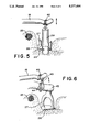
- FIG. 5 illustrates the use of a coupling element for direct inner ear coupling by the oval window
- FIG. 6 shows a coupling to the natural anvil with the anvil-stirrup joint intact
- FIG. 7 shows another type of the positioning of the transducer housing
- FIG. 8 schematically depicts a hearing aid system utilizing the transducer of the present invention implanted in a user's ear.
- a metallic, biocompatible housing 10 that is hermetically sealed on all sides has a top side formed of a, preferably circular, thin membrane 11 that can oscillate.
- the inner side of membrane wall 11 is mechanically, permanently connected with an also preferably circular piezoelectrically active ceramic disk 12 using an electrically conductive adhesive (e.g. LOCKTITE Type 366 glue with LOCKTITE Type 760 activator).
- the diameter of ceramic disk 12 is smaller than the diameter of housing membrane 11.
- the arrangement formed by housing wall 11 and ceramic disk 12 represents an electromechanically active heteromorphic connecting element.
- the surfaces of piezoelectric disk 12 are coated, thinly in comparison to the thickness of the disk, with an electrically conductive material to serve as electrodes.
- Transducer housing 10 consists, including housing membrane 11, of a biocompatible material, preferably titanium, niobium, tantalum or their alloys, or of another biocompatible metal. However, it can be produced, at least partially, from a body-compatible ceramic material, for example, Al 2 O 3 .
- Housing 10 suitably, has a diameter in the range of 6 to 13 mm, preferably about 9 mm.
- Piezoelectric ceramic disk 12 i.a., can consist of lead-zirconate-titanate (PZT) of a thickness that is, suitably, about the same as the thickness of membrane 11.
- the thickness of membrane 11 and ceramic disk 12 are advantageously each in the range of 0.05 to 0.15 mm.
- the radius of housing membrane 11 should be greater than the radius of piezoelectric ceramic disk 12 by a factor of 1.2 to 2.0. A factor of about 1.4 has proven especially advantageous.
- a circular flange 17a of flange member 17 is mechanically, permanently attached to the outer side of housing membrane 11 at its center (e.g., by welding or with biocompatible adhesives).
- the diameter of flange 17a is significantly smaller than the diameter of the membrane 11.
- Short leg 19 of a basically L-shaped, thin bow 18 is mechanically permanently connected with flange member 17, such as by being fixed in an upstanding socket portion 17b thereof.
- bow 18 is bent at a right angle so that a longer leg 20 thereof runs at least approximately parallel to the membrane 11.
- Long leg 20 of bow 18 is slightly longer than the radius of the cylindrical sidewall 10a of the housing 10, so that it slightly projects radially beyond the housing surface 10a, preferably by about 2 mm.
- Bow 18 is configured structurally and consists of such a material that as high as possible a mechanical rigidity with as low as possible a weight is achieved.
- bow 18 is made from a solid or hollow wire, or a carbon fiber reinforced composite material is produced with a high elasticity modulus.
- the diameter of bow 18 is suitably in the range of 0.25 to 1.0 mm and is preferably about 0.5 mm.
- the dimensioning of the connecting element of piezoelectric disk 12/metal membrane 11 with mechanically permanently attached bow 18 is preferably designed so that the dynamic masses per unit of area and rigidities produce a dominant resonant frequency (mode 0/0) in the range of 6 to 12 kHz, preferably about 10 kHz, i.e., a first mechanical resonant frequency which is at the upper limit of the desired transmitting range (for example, about 100 Hz to 12 kHz).
- a dominant resonant frequency in the range of 6 to 12 kHz, preferably about 10 kHz, i.e., a first mechanical resonant frequency which is at the upper limit of the desired transmitting range (for example, about 100 Hz to 12 kHz).
- This means that the system is tuned at or above the high end of the audiologically important frequency range.
- This has, on the one hand, the significant advantage that in the low to medium frequency range, a flat frequency curve of the transducer movement, and thus ideal transmitting properties, are
- housing 10 which is filled with a noble gas, for example, argon, is designed in the shape of a cylindrical disk only in the area of housing membrane 11.
- a noble gas for example, argon
- the opposite end (i.e., lower part) of housing 10 relative to the membrane 11 being step-like with a deeper area being connected to a shallow area by a sloping housing wall 10b, the shallow area being under bow 8.
- the hermetically sealed contact bushing for active electrical terminal 15 of piezoelectric element 12 is in the deeper housing area.
- transducer housing 10 This step-like design of the lower part of transducer housing 10 also has a second reason, which can be seen from FIG. 2, which represents the position of transducer 16 and a possible coupling shape for direct stimulation of the inner ear via the oval window 22.
- transducer housing 10 is not placed in the middle ear (tympanic cavity), but is in an area which is accessible from the mastoid.
- the transducer is guided to the antrum, so that the lengthwise axis of the bent bow part points in the direction of the middle ear.
- the circular membrane area sits here on a bony wall 24 over facial nerve canal 25, or the horizontal semicircular canal, while the deeper part of transducer housing 10 rests on the bottom of mastoid cavity 23.
- the shape of the transducer is optimized, so that in this position of transducer housing 10, the slightly curved end of bow 18 sits as tightly as possible over or beside the stirrup head, so that different types of mechanical elements for coupling to the ossicle chain or directly to the inner ear can be applied.
- the coupling of the oscillating transducer part to the middle ear or to the inner ear is possible with the operating surgeon having an unobstructed view, e.g., through the outer ear canal.
- stirrup base 26 for reasons of clarity, the auditory ossicles are left out except for stirrup base 26 and the partial showing of stirrup leg 27.
- a conventional stirrup prosthesis 28 can be used as a coupling element, which is inserted after opening stirrup base 26 and attaching its metal fastening eyelet 29, not to the natural anvil, but to the curved end of transducer bow 18.
- a great advantage of this transducer embodiment lies in the fact that the application of the coupling elements and their coupling to the middle ear/inner ear can take place under full and direct view of the operating surgeon through the outer ear canal indicated in FIGS. 2 & 8 at 30.
- Another advantage is the space of the middle ear (tympanic cavity) largely remaining free from foreign bodies of large volume.
- transducer housing 10 After optimal positioning with a biocompatible adhesive material, in particular bone cement, the attaching of transducer housing 10 can take place.
- An advantageous embodiment is also a coating of the transducer housing underside, including its step, with bioactive ceramics (e.g., hydroxylapatite), which make possible a permanent growing in and thus the long-term stable positioning of transducer 16.
- transducer 16 Another type of attachment of transducer 16 is represented in FIG. 3.
- the top of transducer housing 10 membrane 11 with joined bow 18
- a cover 33 which rests on the edge of the upper edge of the transducer and that has a pair of oppositely sloping in wall portions 32.
- Bow 18 runs, in this case, in a U-shaped slit 34 in this cover 33, and it is thus largely mechanically protected.
- Cover 33 that can be slipped on from above, is locked in position on transducer housing 10, for example, by interaction of a groove 35 in the housing edge with a lug 36, engaging in groove 35, on cover 33.
- cover 33 On the upper surface, cover 33 has two or more, deformable, preferably wire-shaped, rigid clamps 37, which suitably consist of platinum, titanium, niobium or their alloys, or of high-grade steel.
- clamps 37 are configured so that they allow for the insertion of transducer 16 from the mastoid in the just mentioned way and can be spread out after final positioning so that a bracing on the superimposed bone will takes place at two or more points, so that transducer housing 10 is pressed downward and obliquely in the direction of the middle ear and thus rests permanently on bony wall 24.
- a stabilization can take place with the above-indicated methods (bone cements, bioactive ceramic coatings).
- housing cover 33 Another advantage of housing cover 33 is the protecting and thus damping action on sound waves, which are radiated to a certain extent by oscillating housing membrane 11 and which, with high amplification factors, can lead possibly to feedback problems with the sound-absorbing microphone, when this microphone or a corresponding acoustical feeder to the microphone is positioned near transducer 16.
- FIGS. 4 to 6 possible manners for coupling of the projecting end of vertically oscillating membrane bow 18 are represented on the ossicle chain or directly on the inner ear.
- the auditory ossicle chain does not necessarily have to be interrupted.
- an immobilization of the chain for example by mechanical attachment of the hammer head, is entirely sufficient. Care has only to be taken that the subsequent ossicles (anvil and stirrup) remain mobile, if a coupling to these ossicles is to take place.
- FIG. 4 an embodiment of a coupling element to the stirrup head is represented after natural or artificial interruption of the ossicle chain (e.g., absence or removal of the anvil).
- a small sleeve 39 made from biocompatible material (for example, polyethylene, polytetrafluoroethylene or hydroxylapatite), is slipped on head 40 of the stirrup designated 41 as a whole, and is connected with the other end by a thin metal strip 42 of a type used in conventional stirrup prostheses (for example, made from platinum, platinum alloys or stainless steel) by substantially looping it around the slightly curved end 20a of transducer bow 18.
- the simple and secure positioning of this coupling element is possible by first looping strip 42 around bow 18 in a loose manner.
- the permanent mechanical connection to bow 18 can then take place by pressing shut metal strip 42 or by application of a drop of adhesive (e.g., medical grade silicone).
- FIG. 5 shows a suitable method of direct inner ear coupling via oval window 22 by using a standard, commercially available, stirrup prosthesis 28.
- This type of coupling makes possible the common methodology of strapedectomy with hollowing or removal of base 26 and insertion of a prosthesis 28 which, now, is not attached to the natural anvil but, again, is looped over the end of transducer bow 18. The positioning and attachment of coupling element 28 takes place as described above.
- FIG. 6 represents a methodology of coupling to the natural anvil in an intact anvil-stirrup joint after immobilizing the ossicle chain inlet (hammer head).
- a coupling link 43 formed in the manner of a double hook, has a clamp 44 (e.g., a strip suitably made from platinum, platinum alloy or stainless steel) that at least partially surrounds the long anvil projection 45, and may be in the form of the eyelet of a stirrup prosthesis.
- a second eyelet 46 of coupling link 43 is coupled as described above to transducer bow 18. Thus, approximately the same oscillation direction of stirrup 41 is achieved as in natural stimulation.
- transducer housing 10 is mechanically solidly and replaceably attached in a holding device 48 that is designed, for example, in a pan-shaped manner.
- Holding device 48 consists of a bioactive material, which assures a long-term stable, mechanically permanent growing together in the antrum.
- the explained transducer principle involves the use of a hermetically sealed and biocompatible metallic housing, a wall of which is designed as a membrane that is part of a piezoelectric heteromorphic connecting element.
- the mechanical oscillations of this housing membrane are uncoupled by a permanently attached, mechanically rigid element preferably at the center of the membrane.
- This element is configured as a bow, so that, in positioning the transducer housing from the mastoid adjoining the tympanic cavity, in shape and local position creates an artificial anvil, to which suitable coupling elements can be attached, and which transmit the oscillations of this artificial ossicle mechanically to the inner ear.
- the above-described piezoelectric heteromorphic transducer was produced in the form of laboratory models and tested on humans in intensive clinical tests.
- the oscillations of the transducer membrane from outside were coupled through the outer ear canal by an extended mechanical coupling element to the ossicles of the middle ear, namely to the anvil with an intact anvil-stirrup joint or to the stirrup or the stirrup base in the case of a defective or absent anvil.
- the theoretical operating parameters of the transducer theoretically calculated in advance were able to be fully confirmed in these pretests in practice relative to the achievable stimulation level with low electric transducer voltages and achievable sound quality.
- FIG. 8 represents, generally, a hearing aid system utilizing the transducer of the present invention and a remotely rechargeable and, optionally, programmable electronic unit, the latter mentioned aspects of which are described in greater detail in commonly assigned U.S. Patent Application Ser. No. 07/834,838 filed on even date herewith. To the extent necessary to complete an understanding of this invention, said co-pending application is hereby incorporated by reference.
Abstract
Description
Claims (38)
Applications Claiming Priority (2)
| Application Number | Priority Date | Filing Date | Title |
|---|---|---|---|
| DE4104358A DE4104358A1 (en) | 1991-02-13 | 1991-02-13 | IMPLANTABLE HOER DEVICE FOR EXCITING THE INNER EAR |
| DE4104358 | 1991-02-13 |
Publications (1)
| Publication Number | Publication Date |
|---|---|
| US5277694A true US5277694A (en) | 1994-01-11 |
Family
ID=6424955
Family Applications (1)
| Application Number | Title | Priority Date | Filing Date |
|---|---|---|---|
| US07/834,845 Expired - Lifetime US5277694A (en) | 1991-02-13 | 1992-02-13 | Electromechanical transducer for implantable hearing aids |
Country Status (4)
| Country | Link |
|---|---|
| US (1) | US5277694A (en) |
| EP (1) | EP0499940B1 (en) |
| DE (2) | DE4104358A1 (en) |
| DK (1) | DK0499940T3 (en) |
Cited By (216)
| Publication number | Priority date | Publication date | Assignee | Title |
|---|---|---|---|---|
| US5554096A (en) * | 1993-07-01 | 1996-09-10 | Symphonix | Implantable electromagnetic hearing transducer |
| US5624376A (en) * | 1993-07-01 | 1997-04-29 | Symphonix Devices, Inc. | Implantable and external hearing systems having a floating mass transducer |
| US5707338A (en) * | 1996-08-07 | 1998-01-13 | St. Croix Medical, Inc. | Stapes vibrator |
| WO1998003035A1 (en) * | 1996-07-12 | 1998-01-22 | Symphonix Devices, Inc. | Two stage implantable microphone |
| WO1998006235A1 (en) * | 1996-08-07 | 1998-02-12 | St. Croix Medical, Inc. | Implantable hearing system having multiple transducers |
| US5762583A (en) * | 1996-08-07 | 1998-06-09 | St. Croix Medical, Inc. | Piezoelectric film transducer |
| US5771298A (en) * | 1997-01-13 | 1998-06-23 | Larson-Davis, Inc. | Apparatus and method for simulating a human mastoid |
| US5772575A (en) * | 1995-09-22 | 1998-06-30 | S. George Lesinski | Implantable hearing aid |
| US5800336A (en) * | 1993-07-01 | 1998-09-01 | Symphonix Devices, Inc. | Advanced designs of floating mass transducers |
| US5833626A (en) * | 1996-05-10 | 1998-11-10 | Implex Gmbh Spezialhorgerate | Device for electromechanical stimulation and testing of hearing |
| US5836863A (en) * | 1996-08-07 | 1998-11-17 | St. Croix Medical, Inc. | Hearing aid transducer support |
| US5842967A (en) * | 1996-08-07 | 1998-12-01 | St. Croix Medical, Inc. | Contactless transducer stimulation and sensing of ossicular chain |
| WO1999007436A1 (en) * | 1997-08-07 | 1999-02-18 | St. Croix Medical, Inc. | Electromagnetic input transducers for middle ear sensing |
| US5879283A (en) * | 1996-08-07 | 1999-03-09 | St. Croix Medical, Inc. | Implantable hearing system having multiple transducers |
| US5881158A (en) * | 1996-05-24 | 1999-03-09 | United States Surgical Corporation | Microphones for an implantable hearing aid |
| US5897486A (en) * | 1993-07-01 | 1999-04-27 | Symphonix Devices, Inc. | Dual coil floating mass transducers |
| EP0920239A2 (en) * | 1997-11-26 | 1999-06-02 | IMPLEX GmbH Spezialhörgeräte | Anchoring means for implantable microphone |
| US5913815A (en) * | 1993-07-01 | 1999-06-22 | Symphonix Devices, Inc. | Bone conducting floating mass transducers |
| US5951601A (en) * | 1996-03-25 | 1999-09-14 | Lesinski; S. George | Attaching an implantable hearing aid microactuator |
| US5954628A (en) * | 1997-08-07 | 1999-09-21 | St. Croix Medical, Inc. | Capacitive input transducers for middle ear sensing |
| US5977689A (en) * | 1996-07-19 | 1999-11-02 | Neukermans; Armand P. | Biocompatible, implantable hearing aid microactuator |
| US5984859A (en) * | 1993-01-25 | 1999-11-16 | Lesinski; S. George | Implantable auditory system components and system |
| US6001129A (en) * | 1996-08-07 | 1999-12-14 | St. Croix Medical, Inc. | Hearing aid transducer support |
| US6005955A (en) * | 1996-08-07 | 1999-12-21 | St. Croix Medical, Inc. | Middle ear transducer |
| US6010532A (en) * | 1996-11-25 | 2000-01-04 | St. Croix Medical, Inc. | Dual path implantable hearing assistance device |
| EP0984663A2 (en) | 1998-09-03 | 2000-03-08 | IMPLEX GmbH Spezialhörgeräte | Transducer arrangement for partially or completely implanted hearing -aid |
| EP1011295A2 (en) * | 1998-12-17 | 2000-06-21 | IMPLEX Aktiengesellschaft Hearing Technology | Hermetically tight hearing aid transducer and hearing aid with this transducer |
| US6088619A (en) * | 1999-02-26 | 2000-07-11 | Implex Aktiengesellschaft Hearing Technology | Device and method for aiding the positioning of an external part relative to an implantable part of a charging system for an implantable medical device |
| US6113531A (en) * | 1998-11-18 | 2000-09-05 | Implex Aktiengesellschaft Hearing Technology | Process for optimization of mechanical inner ear stimulation in partially or fully implantable hearing systems |
| US6123660A (en) * | 1998-09-03 | 2000-09-26 | Implex Aktiengesellschaft Hearing Technology | Partially or fully implantable hearing aid |
| EP1041857A2 (en) * | 1999-04-01 | 2000-10-04 | IMPLEX Aktiengesellschaft Hearing Technology | Implantable hearing system with audiometer |
| EP1042991A1 (en) | 1999-04-07 | 2000-10-11 | IMPLEX Aktiengesellschaft Hearing Technology | Implantable positioning and fixation system for actoric and sensoric implants |
| US6131581A (en) * | 1998-06-23 | 2000-10-17 | Dr.-ing. Hans Leysieffer | Process and device for supply of an at least partially implanted active device with electric power |
| DE19859171C2 (en) * | 1998-12-21 | 2000-11-09 | Implex Hear Tech Ag | Implantable hearing aid with tinnitus masker or noiser |
| US6154677A (en) * | 1998-08-20 | 2000-11-28 | Implex Aktiengesellschaft Hearing Technology | Implantable device with a charging current feed arrangement which has a receiving coil |
| US6161046A (en) * | 1996-04-09 | 2000-12-12 | Maniglia; Anthony J. | Totally implantable cochlear implant for improvement of partial and total sensorineural hearing loss |
| US6171229B1 (en) | 1996-08-07 | 2001-01-09 | St. Croix Medical, Inc. | Ossicular transducer attachment for an implantable hearing device |
| US6198971B1 (en) | 1999-04-08 | 2001-03-06 | Implex Aktiengesellschaft Hearing Technology | Implantable system for rehabilitation of a hearing disorder |
| US6214046B1 (en) | 1996-11-25 | 2001-04-10 | St. Croix Medical, Inc. | Method of implanting an implantable hearing assistance device with remote electronics unit |
| US6227204B1 (en) | 1998-08-21 | 2001-05-08 | Implex Aktiengesellschaft Hearing Technology | Device and process for charging of rechargeable batteries of implants |
| US6251062B1 (en) | 1998-12-17 | 2001-06-26 | Implex Aktiengesellschaft Hearing Technology | Implantable device for treatment of tinnitus |
| US6261224B1 (en) | 1996-08-07 | 2001-07-17 | St. Croix Medical, Inc. | Piezoelectric film transducer for cochlear prosthetic |
| US20010009019A1 (en) * | 1997-01-13 | 2001-07-19 | Micro Ear Technology, Inc., D/B/A Micro-Tech. | System for programming hearing aids |
| US6264603B1 (en) | 1997-08-07 | 2001-07-24 | St. Croix Medical, Inc. | Middle ear vibration sensor using multiple transducers |
| US6315710B1 (en) | 1997-07-21 | 2001-11-13 | St. Croix Medical, Inc. | Hearing system with middle ear transducer mount |
| WO2001091515A2 (en) * | 2001-08-17 | 2001-11-29 | Phonak Ag | Implanted hearing aid |
| US6334072B1 (en) | 1999-04-01 | 2001-12-25 | Implex Aktiengesellschaft Hearing Technology | Fully implantable hearing system with telemetric sensor testing |
| DE10041725A1 (en) * | 2000-08-25 | 2002-03-21 | Implex Hear Tech Ag | Device for electromechanical stimulation and hearing testing |
| EP1191816A2 (en) | 2000-09-25 | 2002-03-27 | Cochlear Limited | At least partially implantable hearing system |
| US20020051550A1 (en) * | 2000-08-25 | 2002-05-02 | Hans Leysieffer | Implantable hermetically sealed housing for an implantable medical device and process for producing the same |
| US6398717B1 (en) | 1999-05-21 | 2002-06-04 | Phonak Ag | Device for mechanical coupling of an electromechanical hearing aid converter which can be implanted in a mastoid cavity |
| US20020138115A1 (en) * | 2001-03-26 | 2002-09-26 | Cochlear Limited | Totally implantable hearing system |
| US6473651B1 (en) | 1999-03-02 | 2002-10-29 | Advanced Bionics Corporation | Fluid filled microphone balloon to be implanted in the middle ear |
| US6482144B1 (en) | 1999-10-07 | 2002-11-19 | Phonak Ag | Arrangement for mechanical coupling of a driver to a coupling site of the ossicular chain |
| US6517476B1 (en) | 2000-05-30 | 2003-02-11 | Otologics Llc | Connector for implantable hearing aid |
| US6537200B2 (en) | 2000-03-28 | 2003-03-25 | Cochlear Limited | Partially or fully implantable hearing system |
| US6537199B1 (en) | 1999-07-26 | 2003-03-25 | Phonak Ag | Arrangement for mechanical coupling of a driver to a coupling site of the ossicular chain |
| US6537201B1 (en) | 2001-09-28 | 2003-03-25 | Otologics Llc | Implantable hearing aid with improved sealing |
| US6540661B1 (en) | 1999-10-07 | 2003-04-01 | Phonak Ag | Arrangement for coupling of a driver to a coupling site of the ossicular chain |
| US6540662B2 (en) | 1998-06-05 | 2003-04-01 | St. Croix Medical, Inc. | Method and apparatus for reduced feedback in implantable hearing assistance systems |
| US6547715B1 (en) | 1999-07-08 | 2003-04-15 | Phonak Ag | Arrangement for mechanical coupling of a driver to a coupling site of the ossicular chain |
| US6554762B2 (en) | 2000-08-25 | 2003-04-29 | Cochlear Limited | Implantable hearing system with means for measuring its coupling quality |
| US6554761B1 (en) * | 1999-10-29 | 2003-04-29 | Soundport Corporation | Flextensional microphones for implantable hearing devices |
| US6575894B2 (en) | 2000-04-13 | 2003-06-10 | Cochlear Limited | At least partially implantable system for rehabilitation of a hearing disorder |
| US6592512B2 (en) | 2000-08-11 | 2003-07-15 | Phonak Ag | At least partially implantable system for rehabilitation of a hearing disorder |
| US6629922B1 (en) | 1999-10-29 | 2003-10-07 | Soundport Corporation | Flextensional output actuators for surgically implantable hearing aids |
| US6629923B2 (en) | 2000-09-21 | 2003-10-07 | Phonak Ag | At least partially implantable hearing system with direct mechanical stimulation of a lymphatic space of the inner ear |
| US20030229262A1 (en) * | 2001-11-20 | 2003-12-11 | Easter James Roy | Apparatus and method for ossicular fixation of implantable hearing aid actuator |
| US6676592B2 (en) | 1993-07-01 | 2004-01-13 | Symphonix Devices, Inc. | Dual coil floating mass transducers |
| US6689045B2 (en) | 1998-09-24 | 2004-02-10 | St. Croix Medical, Inc. | Method and apparatus for improving signal quality in implantable hearing systems |
| US6697674B2 (en) | 2000-04-13 | 2004-02-24 | Cochlear Limited | At least partially implantable system for rehabilitation of a hearing disorder |
| US6707920B2 (en) | 2000-12-12 | 2004-03-16 | Otologics Llc | Implantable hearing aid microphone |
| US6730015B2 (en) | 2001-06-01 | 2004-05-04 | Mike Schugt | Flexible transducer supports |
| US6736770B2 (en) | 2000-08-25 | 2004-05-18 | Cochlear Limited | Implantable medical device comprising an hermetically sealed housing |
| US20040147804A1 (en) * | 2003-01-27 | 2004-07-29 | Schneider Robert Edwin | Implantable hearing aid transducer with advanceable actuator to facilitate coupling with the auditory system |
| US20040204921A1 (en) * | 1998-01-09 | 2004-10-14 | Micro Ear Technology, Inc., D/B/A Micro-Tech. | Portable hearing-related analysis system |
| US20040260361A1 (en) * | 2003-04-17 | 2004-12-23 | Peter Gibson | Implantable device having osseointegrating protuberances |
| US20040264725A1 (en) * | 2003-05-19 | 2004-12-30 | Madsen Clair W. | Hearing aid system and transducer with hermetically sealed housing |
| US20050008175A1 (en) * | 1997-01-13 | 2005-01-13 | Hagen Lawrence T. | Portable system for programming hearing aids |
| US20050020873A1 (en) * | 2003-07-23 | 2005-01-27 | Epic Biosonics Inc. | Totally implantable hearing prosthesis |
| US20050036639A1 (en) * | 2001-08-17 | 2005-02-17 | Herbert Bachler | Implanted hearing aids |
| US6888948B2 (en) | 1997-01-13 | 2005-05-03 | Micro Ear Technology, Inc. | Portable system programming hearing aids |
| US20050101832A1 (en) * | 2003-11-07 | 2005-05-12 | Miller Scott A.Iii | Microphone optimized for implant use |
| US20050101831A1 (en) * | 2003-11-07 | 2005-05-12 | Miller Scott A.Iii | Active vibration attenuation for implantable microphone |
| US20050107845A1 (en) * | 2003-03-11 | 2005-05-19 | Wakefield Gregory H. | Using a genetic algorithm to fit a cochlear implant system to a patient |
| US20050203557A1 (en) * | 2001-10-30 | 2005-09-15 | Lesinski S. G. | Implantation method for a hearing aid microactuator implanted into the cochlea |
| US20050222487A1 (en) * | 2004-04-01 | 2005-10-06 | Miller Scott A Iii | Low acceleration sensitivity microphone |
| US20050283263A1 (en) * | 2000-01-20 | 2005-12-22 | Starkey Laboratories, Inc. | Hearing aid systems |
| US20060058573A1 (en) * | 2004-09-16 | 2006-03-16 | Neisz Johann J | Method and apparatus for vibrational damping of implantable hearing aid components |
| US20060116743A1 (en) * | 2002-08-09 | 2006-06-01 | Peter Gibson | Fixation system for an implantable medical device |
| WO2006058368A1 (en) * | 2004-11-30 | 2006-06-08 | Cochlear Acoustics Ltd | Implantable actuator for hearing aid applications |
| US20060155346A1 (en) * | 2005-01-11 | 2006-07-13 | Miller Scott A Iii | Active vibration attenuation for implantable microphone |
| US20060189841A1 (en) * | 2004-10-12 | 2006-08-24 | Vincent Pluvinage | Systems and methods for photo-mechanical hearing transduction |
| US20060235332A1 (en) * | 2002-06-26 | 2006-10-19 | Smoorenburg Guido F | Parametric fitting of a cochlear implant |
| US20060251278A1 (en) * | 2005-05-03 | 2006-11-09 | Rodney Perkins And Associates | Hearing system having improved high frequency response |
| US20070009132A1 (en) * | 2005-07-08 | 2007-01-11 | Miller Scott A Iii | Implantable microphone with shaped chamber |
| US20070014423A1 (en) * | 2005-07-18 | 2007-01-18 | Lotus Technology, Inc. | Behind-the-ear auditory device |
| US20070083078A1 (en) * | 2005-10-06 | 2007-04-12 | Easter James R | Implantable transducer with transverse force application |
| US20070167671A1 (en) * | 2005-11-30 | 2007-07-19 | Miller Scott A Iii | Dual feedback control system for implantable hearing instrument |
| US20070233205A1 (en) * | 2001-06-06 | 2007-10-04 | Cochlear Limited | Monitor for auditory prosthesis |
| US20070255344A1 (en) * | 2006-04-21 | 2007-11-01 | Cochlear Limited | Determining operating parameters for a stimulating medical device |
| US20080046053A1 (en) * | 2006-06-19 | 2008-02-21 | Wagner Timothy A | Apparatus and method for stimulation of biological tissue |
| US20080051623A1 (en) * | 2003-01-27 | 2008-02-28 | Schneider Robert E | Simplified implantable hearing aid transducer apparatus |
| US20080054847A1 (en) * | 2003-07-24 | 2008-03-06 | Cochlear Limited | Battery Characterization Technique |
| US20080107290A1 (en) * | 2003-12-12 | 2008-05-08 | Nec Tokin Corporation | Acoustic vibration generating element |
| US20080132750A1 (en) * | 2005-01-11 | 2008-06-05 | Scott Allan Miller | Adaptive cancellation system for implantable hearing instruments |
| US20080167516A1 (en) * | 1997-12-16 | 2008-07-10 | Vibrant Med-El | Implantable Microphone Having Sensitivity And Frequency Response |
| US20080205679A1 (en) * | 2005-07-18 | 2008-08-28 | Darbut Alexander L | In-Ear Auditory Device and Methods of Using Same |
| US20080240479A1 (en) * | 2006-10-03 | 2008-10-02 | Sonic Innovations, Inc. | Hydrophobic and oleophobic coating and method for preparing the same |
| US20080319508A1 (en) * | 2004-06-15 | 2008-12-25 | Cochlear Americas | Automatic Determination of the Threshold of an Evoked Neural Response |
| US20090039737A1 (en) * | 2007-08-10 | 2009-02-12 | Yasuo Kawada | Method of fabricating case, piezoelectric oscillator, oscillator, electronic appliance, and radio clock |
| US20090092271A1 (en) * | 2007-10-04 | 2009-04-09 | Earlens Corporation | Energy Delivery and Microphone Placement Methods for Improved Comfort in an Open Canal Hearing Aid |
| US20090099658A1 (en) * | 2005-11-10 | 2009-04-16 | Cochlear Limited | Arrangement for the fixation of an implantable medical device |
| US20090112051A1 (en) * | 2007-10-30 | 2009-04-30 | Miller Iii Scott Allan | Observer-based cancellation system for implantable hearing instruments |
| US20090240307A1 (en) * | 2008-01-22 | 2009-09-24 | Cochlear Limited | Recipient-controlled fitting of a hearing prosthesis |
| WO2009124035A3 (en) * | 2008-03-31 | 2009-12-30 | Cochlear Americas | Objective fiting of a hearing prosthesis |
| US20100048982A1 (en) * | 2008-06-17 | 2010-02-25 | Earlens Corporation | Optical Electro-Mechanical Hearing Devices With Separate Power and Signal Components |
| US20100070006A1 (en) * | 2006-06-19 | 2010-03-18 | Wagner Timothy Andrew | Interface apparatus for stimulation of biological tissue |
| US20100069705A1 (en) * | 2008-09-17 | 2010-03-18 | Schumaier Daniel R | Hearing assistance device having reduced mechanical feedback |
| US20100152527A1 (en) * | 2008-12-16 | 2010-06-17 | Ear Lens Corporation | Hearing-aid transducer having an engineered surface |
| US20100152813A1 (en) * | 2003-03-11 | 2010-06-17 | Cochlear Limited | Using a genetic algorithm to fit a medical implant system to a patient |
| US7822479B2 (en) | 2008-01-18 | 2010-10-26 | Otologics, Llc | Connector for implantable hearing aid |
| US20100280307A1 (en) * | 2003-03-11 | 2010-11-04 | Sean Lineaweaver | Using a genetic algorithm in mixed mode device |
| US7840020B1 (en) | 2004-04-01 | 2010-11-23 | Otologics, Llc | Low acceleration sensitivity microphone |
| US20100312040A1 (en) * | 2009-06-05 | 2010-12-09 | SoundBeam LLC | Optically Coupled Acoustic Middle Ear Implant Systems and Methods |
| US20100317914A1 (en) * | 2009-06-15 | 2010-12-16 | SoundBeam LLC | Optically Coupled Active Ossicular Replacement Prosthesis |
| US20110015700A1 (en) * | 2005-10-31 | 2011-01-20 | Dijk Bastiaan Van | Provision of stimulus components having variable perceptability to stimulating device recipient |
| US20110060385A1 (en) * | 2009-09-10 | 2011-03-10 | Lineaweaver Sean K | Determining stimulation level parameters in implant fitting |
| US20110060384A1 (en) * | 2009-09-10 | 2011-03-10 | Cochlear Limited | Determining stimulation level parameters in implant fitting |
| US20110060702A1 (en) * | 2009-09-10 | 2011-03-10 | Cochlear Limited, IP Department | Using a genetic algorithm employing an expedited convergence mechanism |
| US20110060383A1 (en) * | 2009-09-10 | 2011-03-10 | Cochlear Limited, IP Department | Using a genetic algorithm employing dynamic mutation |
| US20110082521A1 (en) * | 2004-06-15 | 2011-04-07 | Andrew Botros | Automatic measurement of an evoked neural response concurrent with an indication of a psychophysics reaction |
| US20110144719A1 (en) * | 2009-06-18 | 2011-06-16 | SoundBeam LLC | Optically Coupled Cochlear Implant Systems and Methods |
| US20110142274A1 (en) * | 2009-06-18 | 2011-06-16 | SoundBeam LLC | Eardrum Implantable Devices For Hearing Systems and Methods |
| US20110152901A1 (en) * | 2009-12-17 | 2011-06-23 | Woodruff Scott A | Implantable Port with Vibratory Feedback |
| US20110159299A1 (en) * | 2006-10-03 | 2011-06-30 | Linforf Mattew R | Hydrophobic coating and method |
| US20110160855A1 (en) * | 2002-08-09 | 2011-06-30 | Peter Gibson | Cochlear implant component having a unitary faceplate |
| US20110270014A1 (en) * | 2010-04-30 | 2011-11-03 | Cochlear Limited | Hearing prosthesis having an on-board fitting system |
| WO2012045852A2 (en) | 2010-10-08 | 2012-04-12 | 3Win N.V. | Implantable actuator for hearing applications |
| WO2012061722A2 (en) | 2010-11-05 | 2012-05-10 | Ethicon Endo-Surgery, Inc. | User feedback through handpiece of surgical instrument |
| US20120165597A1 (en) * | 2010-08-03 | 2012-06-28 | Sonitus Medical, Inc. | Implantable piezoelectric polymer film microphone |
| US8260430B2 (en) | 2010-07-01 | 2012-09-04 | Cochlear Limited | Stimulation channel selection for a stimulating medical device |
| US8300862B2 (en) | 2006-09-18 | 2012-10-30 | Starkey Kaboratories, Inc | Wireless interface for programming hearing assistance devices |
| US8396239B2 (en) | 2008-06-17 | 2013-03-12 | Earlens Corporation | Optical electro-mechanical hearing devices with combined power and signal architectures |
| US8401212B2 (en) | 2007-10-12 | 2013-03-19 | Earlens Corporation | Multifunction system and method for integrated hearing and communication with noise cancellation and feedback management |
| US8657759B2 (en) | 2010-11-08 | 2014-02-25 | Cochlear Limited | Compartmentalized implant fitting software |
| US8715154B2 (en) | 2009-06-24 | 2014-05-06 | Earlens Corporation | Optically coupled cochlear actuator systems and methods |
| US8715153B2 (en) | 2009-06-22 | 2014-05-06 | Earlens Corporation | Optically coupled bone conduction systems and methods |
| US8734476B2 (en) | 2011-10-13 | 2014-05-27 | Ethicon Endo-Surgery, Inc. | Coupling for slip ring assembly and ultrasonic transducer in surgical instrument |
| US8771166B2 (en) | 2009-05-29 | 2014-07-08 | Cochlear Limited | Implantable auditory stimulation system and method with offset implanted microphones |
| US8774929B2 (en) | 2002-08-09 | 2014-07-08 | Cochlear Limited | Cochlear implant component having a unitary faceplate |
| US8824715B2 (en) | 2008-06-17 | 2014-09-02 | Earlens Corporation | Optical electro-mechanical hearing devices with combined power and signal architectures |
| US8845705B2 (en) | 2009-06-24 | 2014-09-30 | Earlens Corporation | Optical cochlear stimulation devices and methods |
| US8892200B2 (en) | 2006-06-19 | 2014-11-18 | Highland Instruments, Inc. | Systems and methods for stimulating tissue using focused energy |
| US20150016649A1 (en) * | 2011-05-24 | 2015-01-15 | Cochlear Limited | Vibration isolation in a bone conduction device |
| US8998939B2 (en) | 2010-11-05 | 2015-04-07 | Ethicon Endo-Surgery, Inc. | Surgical instrument with modular end effector |
| US9000720B2 (en) | 2010-11-05 | 2015-04-07 | Ethicon Endo-Surgery, Inc. | Medical device packaging with charging interface |
| US9011471B2 (en) | 2010-11-05 | 2015-04-21 | Ethicon Endo-Surgery, Inc. | Surgical instrument with pivoting coupling to modular shaft and end effector |
| US9011427B2 (en) | 2010-11-05 | 2015-04-21 | Ethicon Endo-Surgery, Inc. | Surgical instrument safety glasses |
| US9017849B2 (en) | 2010-11-05 | 2015-04-28 | Ethicon Endo-Surgery, Inc. | Power source management for medical device |
| US9017851B2 (en) | 2010-11-05 | 2015-04-28 | Ethicon Endo-Surgery, Inc. | Sterile housing for non-sterile medical device component |
| US9039720B2 (en) | 2010-11-05 | 2015-05-26 | Ethicon Endo-Surgery, Inc. | Surgical instrument with ratcheting rotatable shaft |
| US9050125B2 (en) | 2011-10-10 | 2015-06-09 | Ethicon Endo-Surgery, Inc. | Ultrasonic surgical instrument with modular end effector |
| US9050463B2 (en) | 2011-08-24 | 2015-06-09 | Highland Instruments, Inc. | Systems and methods for stimulating cellular function in tissue |
| US9089338B2 (en) | 2010-11-05 | 2015-07-28 | Ethicon Endo-Surgery, Inc. | Medical device packaging with window for insertion of reusable component |
| US9161803B2 (en) | 2010-11-05 | 2015-10-20 | Ethicon Endo-Surgery, Inc. | Motor driven electrosurgical device with mechanical and electrical feedback |
| US9179226B2 (en) | 2008-02-07 | 2015-11-03 | Advanced Bionics Ag | Partially implantable hearing device |
| US9247986B2 (en) | 2010-11-05 | 2016-02-02 | Ethicon Endo-Surgery, Llc | Surgical instrument with ultrasonic transducer having integral switches |
| US20160158092A1 (en) * | 2014-12-08 | 2016-06-09 | Sorin Crm Sas | System for respiratory disorder therapy with stabilization control of stimulation |
| USD759803S1 (en) | 2014-10-28 | 2016-06-21 | Highland Instruments, Inc. | Adjustable headpiece with anatomical markers |
| US9375255B2 (en) | 2010-11-05 | 2016-06-28 | Ethicon Endo-Surgery, Llc | Surgical instrument handpiece with resiliently biased coupling to modular shaft and end effector |
| US9381058B2 (en) | 2010-11-05 | 2016-07-05 | Ethicon Endo-Surgery, Llc | Recharge system for medical devices |
| US9392377B2 (en) | 2010-12-20 | 2016-07-12 | Earlens Corporation | Anatomically customized ear canal hearing apparatus |
| US9421062B2 (en) | 2010-11-05 | 2016-08-23 | Ethicon Endo-Surgery, Llc | Surgical instrument shaft with resiliently biased coupling to handpiece |
| US9497556B2 (en) | 2010-02-26 | 2016-11-15 | Fraunhofer-Gesellschaft zur Förderung der angewandten Forschung e.V. | Sound transducer for insertion in an ear |
| US20160345107A1 (en) | 2015-05-21 | 2016-11-24 | Cochlear Limited | Advanced management of an implantable sound management system |
| US9526921B2 (en) | 2010-11-05 | 2016-12-27 | Ethicon Endo-Surgery, Llc | User feedback through end effector of surgical instrument |
| US9597143B2 (en) | 2010-11-05 | 2017-03-21 | Ethicon Endo-Surgery, Llc | Sterile medical instrument charging device |
| US20170086778A1 (en) * | 2015-09-29 | 2017-03-30 | International Business Machines Corporation | Capture and analysis of body sounds |
| US9649150B2 (en) | 2010-11-05 | 2017-05-16 | Ethicon Endo-Surgery, Llc | Selective activation of electronic components in medical device |
| US9681820B2 (en) | 2010-10-21 | 2017-06-20 | Highland Instruments, Inc. | Systems for detecting a condition |
| US9729981B2 (en) | 2011-05-12 | 2017-08-08 | Cochlear Limited | Identifying hearing prosthesis actuator resonance peak(s) |
| US9749758B2 (en) | 2008-09-22 | 2017-08-29 | Earlens Corporation | Devices and methods for hearing |
| US9782215B2 (en) | 2010-11-05 | 2017-10-10 | Ethicon Endo-Surgery, Llc | Surgical instrument with ultrasonic transducer having integral switches |
| US9782214B2 (en) | 2010-11-05 | 2017-10-10 | Ethicon Llc | Surgical instrument with sensor and powered control |
| US9913976B2 (en) | 2006-06-19 | 2018-03-13 | Highland Instruments, Inc. | Systems and methods for stimulating and monitoring biological tissue |
| US9924276B2 (en) | 2014-11-26 | 2018-03-20 | Earlens Corporation | Adjustable venting for hearing instruments |
| US9930458B2 (en) | 2014-07-14 | 2018-03-27 | Earlens Corporation | Sliding bias and peak limiting for optical hearing devices |
| US10034103B2 (en) | 2014-03-18 | 2018-07-24 | Earlens Corporation | High fidelity and reduced feedback contact hearing apparatus and methods |
| US10085792B2 (en) | 2010-11-05 | 2018-10-02 | Ethicon Llc | Surgical instrument with motorized attachment feature |
| US10136938B2 (en) | 2014-10-29 | 2018-11-27 | Ethicon Llc | Electrosurgical instrument with sensor |
| CN109040931A (en) * | 2017-06-09 | 2018-12-18 | 大北欧听力公司 | blocking control system and hearing instrument for hearing instrument |
| US10178483B2 (en) | 2015-12-30 | 2019-01-08 | Earlens Corporation | Light based hearing systems, apparatus, and methods |
| US10292601B2 (en) | 2015-10-02 | 2019-05-21 | Earlens Corporation | Wearable customized ear canal apparatus |
| US10292897B2 (en) | 2014-12-08 | 2019-05-21 | Sorin Crm Sas | System for respiratory disorder therapy with selection of stimulation strategies |
| US10292898B2 (en) | 2014-12-08 | 2019-05-21 | Sorin Crm Sas | Device for optimization of sleep apnea syndrome therapy by kinesthetic stimulation |
| US10321247B2 (en) | 2015-11-27 | 2019-06-11 | Cochlear Limited | External component with inductance and mechanical vibratory functionality |
| US10412512B2 (en) | 2006-05-30 | 2019-09-10 | Soundmed, Llc | Methods and apparatus for processing audio signals |
| US10484805B2 (en) | 2009-10-02 | 2019-11-19 | Soundmed, Llc | Intraoral appliance for sound transmission via bone conduction |
| US10492010B2 (en) | 2015-12-30 | 2019-11-26 | Earlens Corporations | Damping in contact hearing systems |
| US10537380B2 (en) | 2010-11-05 | 2020-01-21 | Ethicon Llc | Surgical instrument with charging station and wireless communication |
| US10555100B2 (en) | 2009-06-22 | 2020-02-04 | Earlens Corporation | Round window coupled hearing systems and methods |
| US10660695B2 (en) | 2010-11-05 | 2020-05-26 | Ethicon Llc | Sterile medical instrument charging device |
| US10848883B2 (en) | 2011-05-24 | 2020-11-24 | Cochlear Limited | Convertibility of a bone conduction device |
| US10881448B2 (en) | 2010-11-05 | 2021-01-05 | Ethicon Llc | Cam driven coupling between ultrasonic transducer and waveguide in surgical instrument |
| US10959769B2 (en) | 2010-11-05 | 2021-03-30 | Ethicon Llc | Surgical instrument with slip ring assembly to power ultrasonic transducer |
| US10973563B2 (en) | 2010-11-05 | 2021-04-13 | Ethicon Llc | Surgical instrument with charging devices |
| US11071869B2 (en) | 2016-02-24 | 2021-07-27 | Cochlear Limited | Implantable device having removable portion |
| US11089413B2 (en) | 2012-08-28 | 2021-08-10 | Cochlear Limited | Removable attachment of a passive transcutaneous bone conduction device with limited skin deformation |
| US11102594B2 (en) | 2016-09-09 | 2021-08-24 | Earlens Corporation | Contact hearing systems, apparatus and methods |
| US11166114B2 (en) | 2016-11-15 | 2021-11-02 | Earlens Corporation | Impression procedure |
| US11212626B2 (en) | 2018-04-09 | 2021-12-28 | Earlens Corporation | Dynamic filter |
| US11245991B2 (en) | 2013-03-15 | 2022-02-08 | Cochlear Limited | Determining impedance-related phenomena in vibrating actuator and identifying device system characteristics based thereon |
| US11350226B2 (en) | 2015-12-30 | 2022-05-31 | Earlens Corporation | Charging protocol for rechargeable hearing systems |
| US11516603B2 (en) | 2018-03-07 | 2022-11-29 | Earlens Corporation | Contact hearing device and retention structure materials |
| US11889272B2 (en) | 2011-10-12 | 2024-01-30 | Cochlear Limited | Implantable medical device |
Families Citing this family (11)
| Publication number | Priority date | Publication date | Assignee | Title |
|---|---|---|---|---|
| DE4221866C2 (en) * | 1992-07-03 | 1994-06-23 | Guenter Hortmann | Hearing aid for stimulating the inner ear |
| US5814095A (en) * | 1996-09-18 | 1998-09-29 | Implex Gmbh Spezialhorgerate | Implantable microphone and implantable hearing aids utilizing same |
| DE19638158C2 (en) * | 1996-09-18 | 2000-08-31 | Implex Hear Tech Ag | Implantable microphone |
| DE19738587C1 (en) | 1997-09-03 | 1999-05-27 | Implex Gmbh | Arrangement for setting and fixing the relative position of two elements of an active or passive hearing implant |
| DE19745331A1 (en) * | 1997-10-14 | 1999-04-15 | Schumann Klaus | Electronic hearing aid |
| DE19752447C2 (en) * | 1997-11-26 | 1999-12-30 | Implex Hear Tech Ag | Fixation element for an implantable microphone |
| DE10018360C2 (en) | 2000-04-13 | 2002-10-10 | Cochlear Ltd | At least partially implantable system for the rehabilitation of a hearing impairment |
| DE10031832C2 (en) | 2000-06-30 | 2003-04-30 | Cochlear Ltd | Hearing aid for the rehabilitation of a hearing disorder |
| DE102004038078B4 (en) * | 2004-07-30 | 2010-11-25 | Technische Universität Dresden | Implantable hearing aid part |
| EP1846089B1 (en) * | 2005-01-27 | 2016-08-31 | Cochlear Limited | Implantable medical device |
| GB2509450A (en) | 2011-10-31 | 2014-07-02 | Schlumberger Holdings | Inversion-based workflow for processing nuclear density images in high-angle and horizontal wells |
Citations (16)
| Publication number | Priority date | Publication date | Assignee | Title |
|---|---|---|---|---|
| US3594514A (en) * | 1970-01-02 | 1971-07-20 | Medtronic Inc | Hearing aid with piezoelectric ceramic element |
| US3712962A (en) * | 1971-04-05 | 1973-01-23 | J Epley | Implantable piezoelectric hearing aid |
| US3764748A (en) * | 1972-05-19 | 1973-10-09 | J Branch | Implanted hearing aids |
| US3870832A (en) * | 1972-07-18 | 1975-03-11 | John M Fredrickson | Implantable electromagnetic hearing aid |
| US3882285A (en) * | 1973-10-09 | 1975-05-06 | Vicon Instr Company | Implantable hearing aid and method of improving hearing |
| DE2825233A1 (en) * | 1977-06-21 | 1979-01-04 | Georges Ducommun | HOERGERAET |
| US4150262A (en) * | 1974-11-18 | 1979-04-17 | Hiroshi Ono | Piezoelectric bone conductive in ear voice sounds transmitting and receiving apparatus |
| US4606329A (en) * | 1985-05-22 | 1986-08-19 | Xomed, Inc. | Implantable electromagnetic middle-ear bone-conduction hearing aid device |
| GB2176078A (en) * | 1985-05-23 | 1986-12-10 | Bristol Myers Co | Direct bone conduction hearing aid |
| EP0242038A2 (en) * | 1986-03-07 | 1987-10-21 | SMITH & NEPHEW RICHARDS, INC. | Magnetic induction hearing aid |
| US4729366A (en) * | 1984-12-04 | 1988-03-08 | Medical Devices Group, Inc. | Implantable hearing aid and method of improving hearing |
| US4756312A (en) * | 1984-03-22 | 1988-07-12 | Advanced Hearing Technology, Inc. | Magnetic attachment device for insertion and removal of hearing aid |
| EP0341902A2 (en) * | 1988-05-10 | 1989-11-15 | 3M Hearing Health Aktiebolag | Hearing aid programming interface |
| US4988333A (en) * | 1988-09-09 | 1991-01-29 | Storz Instrument Company | Implantable middle ear hearing aid system and acoustic coupler therefor |
| US5015225A (en) * | 1985-05-22 | 1991-05-14 | Xomed, Inc. | Implantable electromagnetic middle-ear bone-conduction hearing aid device |
| US5015224A (en) * | 1988-10-17 | 1991-05-14 | Maniglia Anthony J | Partially implantable hearing aid device |
Family Cites Families (2)
| Publication number | Priority date | Publication date | Assignee | Title |
|---|---|---|---|---|
| AT349552B (en) * | 1977-02-15 | 1979-04-10 | Viennatone Gmbh | CONDUCTOR BUTTON, ESPECIALLY FOR BONE EAR GLASSES |
| DE3918086C1 (en) * | 1989-06-02 | 1990-09-27 | Hortmann Gmbh, 7449 Neckartenzlingen, De |
-
1991
- 1991-02-13 DE DE4104358A patent/DE4104358A1/en active Granted
-
1992
- 1992-02-10 DK DK92102209.1T patent/DK0499940T3/en active
- 1992-02-10 DE DE59200333T patent/DE59200333D1/en not_active Expired - Fee Related
- 1992-02-10 EP EP92102209A patent/EP0499940B1/en not_active Expired - Lifetime
- 1992-02-13 US US07/834,845 patent/US5277694A/en not_active Expired - Lifetime
Patent Citations (20)
| Publication number | Priority date | Publication date | Assignee | Title |
|---|---|---|---|---|
| US3594514A (en) * | 1970-01-02 | 1971-07-20 | Medtronic Inc | Hearing aid with piezoelectric ceramic element |
| US3712962A (en) * | 1971-04-05 | 1973-01-23 | J Epley | Implantable piezoelectric hearing aid |
| US3764748A (en) * | 1972-05-19 | 1973-10-09 | J Branch | Implanted hearing aids |
| US3870832A (en) * | 1972-07-18 | 1975-03-11 | John M Fredrickson | Implantable electromagnetic hearing aid |
| GB1440724A (en) * | 1972-07-18 | 1976-06-23 | Fredrickson J M | Implantable electromagnetic hearing aid |
| US3882285A (en) * | 1973-10-09 | 1975-05-06 | Vicon Instr Company | Implantable hearing aid and method of improving hearing |
| US4150262A (en) * | 1974-11-18 | 1979-04-17 | Hiroshi Ono | Piezoelectric bone conductive in ear voice sounds transmitting and receiving apparatus |
| DE2825233A1 (en) * | 1977-06-21 | 1979-01-04 | Georges Ducommun | HOERGERAET |
| US4756312A (en) * | 1984-03-22 | 1988-07-12 | Advanced Hearing Technology, Inc. | Magnetic attachment device for insertion and removal of hearing aid |
| US4729366A (en) * | 1984-12-04 | 1988-03-08 | Medical Devices Group, Inc. | Implantable hearing aid and method of improving hearing |
| DE3617118A1 (en) * | 1985-05-22 | 1987-02-05 | Bristol Myers Co | IMPLANTABLE ELECTROMAGNETIC EARRING AID |
| GB2188209A (en) * | 1985-05-22 | 1987-09-23 | Bristol Myers Co | Implantable electromagnetic middle-ear bone-conduction hearing aid device |
| US4606329A (en) * | 1985-05-22 | 1986-08-19 | Xomed, Inc. | Implantable electromagnetic middle-ear bone-conduction hearing aid device |
| US5015225A (en) * | 1985-05-22 | 1991-05-14 | Xomed, Inc. | Implantable electromagnetic middle-ear bone-conduction hearing aid device |
| GB2176078A (en) * | 1985-05-23 | 1986-12-10 | Bristol Myers Co | Direct bone conduction hearing aid |
| EP0242038A2 (en) * | 1986-03-07 | 1987-10-21 | SMITH & NEPHEW RICHARDS, INC. | Magnetic induction hearing aid |
| EP0263254A1 (en) * | 1986-08-11 | 1988-04-13 | Medical Devices Group, Inc. | Implantable hearing aid |
| EP0341902A2 (en) * | 1988-05-10 | 1989-11-15 | 3M Hearing Health Aktiebolag | Hearing aid programming interface |
| US4988333A (en) * | 1988-09-09 | 1991-01-29 | Storz Instrument Company | Implantable middle ear hearing aid system and acoustic coupler therefor |
| US5015224A (en) * | 1988-10-17 | 1991-05-14 | Maniglia Anthony J | Partially implantable hearing aid device |
Non-Patent Citations (4)
| Title |
|---|
| Adv. Audiol., vol. 4, pp. 23 43; 51 72 and 107 116 (Karger, Basel 1988). * |
| Adv. Audiol., vol. 4, pp. 23-43; 51-72 and 107-116 (Karger, Basel 1988). |
| Arch Otolaryngol Head Nech Surg. vol. 113, Aug. 1987 Implantable Hearing Aid, Naoaki Yanagihara, MD et al., pp. 869 872. * |
| Arch Otolaryngol Head Nech Surg.-vol. 113, Aug. 1987 Implantable Hearing Aid, Naoaki Yanagihara, MD et al., pp. 869-872. |
Cited By (424)
| Publication number | Priority date | Publication date | Assignee | Title |
|---|---|---|---|---|
| US5984859A (en) * | 1993-01-25 | 1999-11-16 | Lesinski; S. George | Implantable auditory system components and system |
| US5857958A (en) * | 1993-07-01 | 1999-01-12 | Symphonix Devices, Inc. | Implantable and external hearing systems having a floating mass transducer |
| US5624376A (en) * | 1993-07-01 | 1997-04-29 | Symphonix Devices, Inc. | Implantable and external hearing systems having a floating mass transducer |
| US6475134B1 (en) | 1993-07-01 | 2002-11-05 | Symphonix Devices, Inc. | Dual coil floating mass transducers |
| US5554096A (en) * | 1993-07-01 | 1996-09-10 | Symphonix | Implantable electromagnetic hearing transducer |
| US5913815A (en) * | 1993-07-01 | 1999-06-22 | Symphonix Devices, Inc. | Bone conducting floating mass transducers |
| US6676592B2 (en) | 1993-07-01 | 2004-01-13 | Symphonix Devices, Inc. | Dual coil floating mass transducers |
| US5897486A (en) * | 1993-07-01 | 1999-04-27 | Symphonix Devices, Inc. | Dual coil floating mass transducers |
| US5800336A (en) * | 1993-07-01 | 1998-09-01 | Symphonix Devices, Inc. | Advanced designs of floating mass transducers |
| EP0873668A1 (en) * | 1995-09-22 | 1998-10-28 | Lesinski Ltd., Inc. | Implantable hearing aid |
| US5772575A (en) * | 1995-09-22 | 1998-06-30 | S. George Lesinski | Implantable hearing aid |
| EP0873668A4 (en) * | 1995-09-22 | 2004-03-31 | Lesinski Ltd Inc | Implantable hearing aid |
| US5951601A (en) * | 1996-03-25 | 1999-09-14 | Lesinski; S. George | Attaching an implantable hearing aid microactuator |
| US6161046A (en) * | 1996-04-09 | 2000-12-12 | Maniglia; Anthony J. | Totally implantable cochlear implant for improvement of partial and total sensorineural hearing loss |
| US5833626A (en) * | 1996-05-10 | 1998-11-10 | Implex Gmbh Spezialhorgerate | Device for electromechanical stimulation and testing of hearing |
| US5881158A (en) * | 1996-05-24 | 1999-03-09 | United States Surgical Corporation | Microphones for an implantable hearing aid |
| WO1998003035A1 (en) * | 1996-07-12 | 1998-01-22 | Symphonix Devices, Inc. | Two stage implantable microphone |
| US5977689A (en) * | 1996-07-19 | 1999-11-02 | Neukermans; Armand P. | Biocompatible, implantable hearing aid microactuator |
| US6153966A (en) * | 1996-07-19 | 2000-11-28 | Neukermans; Armand P. | Biocompatible, implantable hearing aid microactuator |
| US5997466A (en) * | 1996-08-07 | 1999-12-07 | St. Croix Medical, Inc. | Implantable hearing system having multiple transducers |
| WO1998006235A1 (en) * | 1996-08-07 | 1998-02-12 | St. Croix Medical, Inc. | Implantable hearing system having multiple transducers |
| US6001129A (en) * | 1996-08-07 | 1999-12-14 | St. Croix Medical, Inc. | Hearing aid transducer support |
| US5762583A (en) * | 1996-08-07 | 1998-06-09 | St. Croix Medical, Inc. | Piezoelectric film transducer |
| US6005955A (en) * | 1996-08-07 | 1999-12-21 | St. Croix Medical, Inc. | Middle ear transducer |
| US20040181117A1 (en) * | 1996-08-07 | 2004-09-16 | Adams Theodore P. | Piezoelectric film transducer |
| US6261224B1 (en) | 1996-08-07 | 2001-07-17 | St. Croix Medical, Inc. | Piezoelectric film transducer for cochlear prosthetic |
| US5836863A (en) * | 1996-08-07 | 1998-11-17 | St. Croix Medical, Inc. | Hearing aid transducer support |
| US6171229B1 (en) | 1996-08-07 | 2001-01-09 | St. Croix Medical, Inc. | Ossicular transducer attachment for an implantable hearing device |
| US5879283A (en) * | 1996-08-07 | 1999-03-09 | St. Croix Medical, Inc. | Implantable hearing system having multiple transducers |
| US6488616B1 (en) | 1996-08-07 | 2002-12-03 | St. Croix Medical, Inc. | Hearing aid transducer support |
| US5842967A (en) * | 1996-08-07 | 1998-12-01 | St. Croix Medical, Inc. | Contactless transducer stimulation and sensing of ossicular chain |
| US6050933A (en) * | 1996-08-07 | 2000-04-18 | St. Croix Medical, Inc. | Hearing aid transducer support |
| US5707338A (en) * | 1996-08-07 | 1998-01-13 | St. Croix Medical, Inc. | Stapes vibrator |
| US6214046B1 (en) | 1996-11-25 | 2001-04-10 | St. Croix Medical, Inc. | Method of implanting an implantable hearing assistance device with remote electronics unit |
| US6491722B1 (en) | 1996-11-25 | 2002-12-10 | St. Croix Medical, Inc. | Dual path implantable hearing assistance device |
| US6010532A (en) * | 1996-11-25 | 2000-01-04 | St. Croix Medical, Inc. | Dual path implantable hearing assistance device |
| US7929723B2 (en) | 1997-01-13 | 2011-04-19 | Micro Ear Technology, Inc. | Portable system for programming hearing aids |
| US20050196002A1 (en) * | 1997-01-13 | 2005-09-08 | Micro Ear Technology, Inc., D/B/A Micro-Tech | Portable system for programming hearing aids |
| US5771298A (en) * | 1997-01-13 | 1998-06-23 | Larson-Davis, Inc. | Apparatus and method for simulating a human mastoid |
| US20010009019A1 (en) * | 1997-01-13 | 2001-07-19 | Micro Ear Technology, Inc., D/B/A Micro-Tech. | System for programming hearing aids |
| US20030014566A1 (en) * | 1997-01-13 | 2003-01-16 | Micro Ear Technology, Inc., D/B/A Micro-Tech | System for programming hearing aids |
| US7451256B2 (en) | 1997-01-13 | 2008-11-11 | Micro Ear Technology, Inc. | Portable system for programming hearing aids |
| US20100086153A1 (en) * | 1997-01-13 | 2010-04-08 | Micro Ear Technology, Inc. D/B/A Micro-Tech | Portable system for programming hearing aids |
| US6851048B2 (en) | 1997-01-13 | 2005-02-01 | Micro Ear Technology, Inc. | System for programming hearing aids |
| US7787647B2 (en) | 1997-01-13 | 2010-08-31 | Micro Ear Technology, Inc. | Portable system for programming hearing aids |
| US6888948B2 (en) | 1997-01-13 | 2005-05-03 | Micro Ear Technology, Inc. | Portable system programming hearing aids |
| US20050008175A1 (en) * | 1997-01-13 | 2005-01-13 | Hagen Lawrence T. | Portable system for programming hearing aids |
| US6315710B1 (en) | 1997-07-21 | 2001-11-13 | St. Croix Medical, Inc. | Hearing system with middle ear transducer mount |
| US5993376A (en) * | 1997-08-07 | 1999-11-30 | St. Croix Medical, Inc. | Electromagnetic input transducers for middle ear sensing |
| US5954628A (en) * | 1997-08-07 | 1999-09-21 | St. Croix Medical, Inc. | Capacitive input transducers for middle ear sensing |
| WO1999007436A1 (en) * | 1997-08-07 | 1999-02-18 | St. Croix Medical, Inc. | Electromagnetic input transducers for middle ear sensing |
| US6264603B1 (en) | 1997-08-07 | 2001-07-24 | St. Croix Medical, Inc. | Middle ear vibration sensor using multiple transducers |
| US5999632A (en) * | 1997-11-26 | 1999-12-07 | Implex Aktiengesellschaft Hearing Technology | Fixation element for an implantable microphone |
| EP0920239A2 (en) * | 1997-11-26 | 1999-06-02 | IMPLEX GmbH Spezialhörgeräte | Anchoring means for implantable microphone |
| EP0920239A3 (en) * | 1997-11-26 | 2006-08-02 | Phonak Ag | Anchoring means for implantable microphone |
| US20080167516A1 (en) * | 1997-12-16 | 2008-07-10 | Vibrant Med-El | Implantable Microphone Having Sensitivity And Frequency Response |
| US7955250B2 (en) * | 1997-12-16 | 2011-06-07 | Med-El Elektromedizinische Geraete Gmbh | Implantable microphone having sensitivity and frequency response |
| US20040204921A1 (en) * | 1998-01-09 | 2004-10-14 | Micro Ear Technology, Inc., D/B/A Micro-Tech. | Portable hearing-related analysis system |
| US6895345B2 (en) | 1998-01-09 | 2005-05-17 | Micro Ear Technology, Inc. | Portable hearing-related analysis system |
| US6755778B2 (en) | 1998-06-05 | 2004-06-29 | St. Croix Medical, Inc. | Method and apparatus for reduced feedback in implantable hearing assistance systems |
| US6540662B2 (en) | 1998-06-05 | 2003-04-01 | St. Croix Medical, Inc. | Method and apparatus for reduced feedback in implantable hearing assistance systems |
| US6131581A (en) * | 1998-06-23 | 2000-10-17 | Dr.-ing. Hans Leysieffer | Process and device for supply of an at least partially implanted active device with electric power |
| US6154677A (en) * | 1998-08-20 | 2000-11-28 | Implex Aktiengesellschaft Hearing Technology | Implantable device with a charging current feed arrangement which has a receiving coil |
| US6227204B1 (en) | 1998-08-21 | 2001-05-08 | Implex Aktiengesellschaft Hearing Technology | Device and process for charging of rechargeable batteries of implants |
| DE19840212C2 (en) * | 1998-09-03 | 2001-08-02 | Implex Hear Tech Ag | Transducer arrangement for partially or fully implantable hearing aids |
| US6162169A (en) * | 1998-09-03 | 2000-12-19 | Implex Aktiengesellschaft Hearing Technology | Transducer arrangement for partially or fully implantable hearing aids |
| US6123660A (en) * | 1998-09-03 | 2000-09-26 | Implex Aktiengesellschaft Hearing Technology | Partially or fully implantable hearing aid |
| EP0984663A2 (en) | 1998-09-03 | 2000-03-08 | IMPLEX GmbH Spezialhörgeräte | Transducer arrangement for partially or completely implanted hearing -aid |
| US6689045B2 (en) | 1998-09-24 | 2004-02-10 | St. Croix Medical, Inc. | Method and apparatus for improving signal quality in implantable hearing systems |
| US6113531A (en) * | 1998-11-18 | 2000-09-05 | Implex Aktiengesellschaft Hearing Technology | Process for optimization of mechanical inner ear stimulation in partially or fully implantable hearing systems |
| AU753831B2 (en) * | 1998-12-17 | 2002-10-31 | Cochlear Limited | Implantable device for treatment of tinnitus |
| EP1011295A3 (en) * | 1998-12-17 | 2006-05-24 | Phonak Ag | Hermetically tight hearing aid transducer and hearing aid with this transducer |
| EP1011295A2 (en) * | 1998-12-17 | 2000-06-21 | IMPLEX Aktiengesellschaft Hearing Technology | Hermetically tight hearing aid transducer and hearing aid with this transducer |
| US6600825B1 (en) | 1998-12-17 | 2003-07-29 | Phonak Ag | Hermetically sealed hearing aid converter and hearing aids with this converter |
| US6251062B1 (en) | 1998-12-17 | 2001-06-26 | Implex Aktiengesellschaft Hearing Technology | Implantable device for treatment of tinnitus |
| DE19859171C2 (en) * | 1998-12-21 | 2000-11-09 | Implex Hear Tech Ag | Implantable hearing aid with tinnitus masker or noiser |
| US6394947B1 (en) | 1998-12-21 | 2002-05-28 | Cochlear Limited | Implantable hearing aid with tinnitus masker or noiser |
| DE19908438C2 (en) * | 1999-02-26 | 2003-05-15 | Cochlear Ltd | Device and method for supporting the positioning of an external transmitting part with respect to an implantable receiving part of a charging system of an implantable medical device |
| US6088619A (en) * | 1999-02-26 | 2000-07-11 | Implex Aktiengesellschaft Hearing Technology | Device and method for aiding the positioning of an external part relative to an implantable part of a charging system for an implantable medical device |
| US6473651B1 (en) | 1999-03-02 | 2002-10-29 | Advanced Bionics Corporation | Fluid filled microphone balloon to be implanted in the middle ear |
| EP1041857A2 (en) * | 1999-04-01 | 2000-10-04 | IMPLEX Aktiengesellschaft Hearing Technology | Implantable hearing system with audiometer |
| US6334072B1 (en) | 1999-04-01 | 2001-12-25 | Implex Aktiengesellschaft Hearing Technology | Fully implantable hearing system with telemetric sensor testing |
| EP1041857A3 (en) * | 1999-04-01 | 2006-05-31 | Cochlear Limited | Implantable hearing system with audiometer |
| US6788790B1 (en) | 1999-04-01 | 2004-09-07 | Cochlear Limited | Implantable hearing system with audiometer |
| DE19915684B4 (en) * | 1999-04-07 | 2005-12-01 | Phonak Ag | Implantable positioning and fixation system for actuator and sensory implants |
| EP1042991A1 (en) | 1999-04-07 | 2000-10-11 | IMPLEX Aktiengesellschaft Hearing Technology | Implantable positioning and fixation system for actoric and sensoric implants |
| US6390970B1 (en) | 1999-04-07 | 2002-05-21 | Phonak Ag | Implantable positioning and fixing system for actuator and sensor implants |
| US6198971B1 (en) | 1999-04-08 | 2001-03-06 | Implex Aktiengesellschaft Hearing Technology | Implantable system for rehabilitation of a hearing disorder |
| US6398717B1 (en) | 1999-05-21 | 2002-06-04 | Phonak Ag | Device for mechanical coupling of an electromechanical hearing aid converter which can be implanted in a mastoid cavity |
| US6547715B1 (en) | 1999-07-08 | 2003-04-15 | Phonak Ag | Arrangement for mechanical coupling of a driver to a coupling site of the ossicular chain |
| US6537199B1 (en) | 1999-07-26 | 2003-03-25 | Phonak Ag | Arrangement for mechanical coupling of a driver to a coupling site of the ossicular chain |
| US6540661B1 (en) | 1999-10-07 | 2003-04-01 | Phonak Ag | Arrangement for coupling of a driver to a coupling site of the ossicular chain |
| US6482144B1 (en) | 1999-10-07 | 2002-11-19 | Phonak Ag | Arrangement for mechanical coupling of a driver to a coupling site of the ossicular chain |
| US6629922B1 (en) | 1999-10-29 | 2003-10-07 | Soundport Corporation | Flextensional output actuators for surgically implantable hearing aids |
| US6554761B1 (en) * | 1999-10-29 | 2003-04-29 | Soundport Corporation | Flextensional microphones for implantable hearing devices |
| US20050283263A1 (en) * | 2000-01-20 | 2005-12-22 | Starkey Laboratories, Inc. | Hearing aid systems |
| US9344817B2 (en) | 2000-01-20 | 2016-05-17 | Starkey Laboratories, Inc. | Hearing aid systems |
| US8503703B2 (en) | 2000-01-20 | 2013-08-06 | Starkey Laboratories, Inc. | Hearing aid systems |
| US9357317B2 (en) | 2000-01-20 | 2016-05-31 | Starkey Laboratories, Inc. | Hearing aid systems |
| US6537200B2 (en) | 2000-03-28 | 2003-03-25 | Cochlear Limited | Partially or fully implantable hearing system |
| US6575894B2 (en) | 2000-04-13 | 2003-06-10 | Cochlear Limited | At least partially implantable system for rehabilitation of a hearing disorder |
| US6697674B2 (en) | 2000-04-13 | 2004-02-24 | Cochlear Limited | At least partially implantable system for rehabilitation of a hearing disorder |
| US20040172102A1 (en) * | 2000-04-13 | 2004-09-02 | Cochlear Limited | At least partially implantable system for rehabilitation of a hearing disorder |
| US6517476B1 (en) | 2000-05-30 | 2003-02-11 | Otologics Llc | Connector for implantable hearing aid |
| US6592512B2 (en) | 2000-08-11 | 2003-07-15 | Phonak Ag | At least partially implantable system for rehabilitation of a hearing disorder |
| US6736770B2 (en) | 2000-08-25 | 2004-05-18 | Cochlear Limited | Implantable medical device comprising an hermetically sealed housing |
| US6554762B2 (en) | 2000-08-25 | 2003-04-29 | Cochlear Limited | Implantable hearing system with means for measuring its coupling quality |
| DE10041725A1 (en) * | 2000-08-25 | 2002-03-21 | Implex Hear Tech Ag | Device for electromechanical stimulation and hearing testing |
| US6663575B2 (en) | 2000-08-25 | 2003-12-16 | Phonak Ag | Device for electromechanical stimulation and testing of hearing |
| DE10041725B4 (en) * | 2000-08-25 | 2004-04-29 | Phonak Ag | Device for electromechanical stimulation and testing of the hearing |
| US20020051550A1 (en) * | 2000-08-25 | 2002-05-02 | Hans Leysieffer | Implantable hermetically sealed housing for an implantable medical device and process for producing the same |
| US8105229B2 (en) | 2000-09-15 | 2012-01-31 | Cochlear Limited | At least partially implantable hearing system |
| US20070249890A1 (en) * | 2000-09-15 | 2007-10-25 | Cochlear Limited | At least partially implantable hearing system |
| US6629923B2 (en) | 2000-09-21 | 2003-10-07 | Phonak Ag | At least partially implantable hearing system with direct mechanical stimulation of a lymphatic space of the inner ear |
| EP1191816A2 (en) | 2000-09-25 | 2002-03-27 | Cochlear Limited | At least partially implantable hearing system |
| US7226406B2 (en) | 2000-09-25 | 2007-06-05 | Cochlear Limited | At least partially implantable hearing system |
| US6707920B2 (en) | 2000-12-12 | 2004-03-16 | Otologics Llc | Implantable hearing aid microphone |
| US6807445B2 (en) | 2001-03-26 | 2004-10-19 | Cochlear Limited | Totally implantable hearing system |
| US20020138115A1 (en) * | 2001-03-26 | 2002-09-26 | Cochlear Limited | Totally implantable hearing system |
| US6730015B2 (en) | 2001-06-01 | 2004-05-04 | Mike Schugt | Flexible transducer supports |
| US20070233205A1 (en) * | 2001-06-06 | 2007-10-04 | Cochlear Limited | Monitor for auditory prosthesis |
| WO2001091515A3 (en) * | 2001-08-17 | 2002-10-10 | Phonak Ag | Implanted hearing aid |
| US6869391B2 (en) | 2001-08-17 | 2005-03-22 | Phonak Ag | Implanted hearing aids |
| US20050036639A1 (en) * | 2001-08-17 | 2005-02-17 | Herbert Bachler | Implanted hearing aids |
| WO2001091515A2 (en) * | 2001-08-17 | 2001-11-29 | Phonak Ag | Implanted hearing aid |
| US6537201B1 (en) | 2001-09-28 | 2003-03-25 | Otologics Llc | Implantable hearing aid with improved sealing |
| US8147544B2 (en) | 2001-10-30 | 2012-04-03 | Otokinetics Inc. | Therapeutic appliance for cochlea |
| US20050203557A1 (en) * | 2001-10-30 | 2005-09-15 | Lesinski S. G. | Implantation method for a hearing aid microactuator implanted into the cochlea |
| US8876689B2 (en) | 2001-10-30 | 2014-11-04 | Otokinetics Inc. | Hearing aid microactuator |
| US20030229262A1 (en) * | 2001-11-20 | 2003-12-11 | Easter James Roy | Apparatus and method for ossicular fixation of implantable hearing aid actuator |
| US20090043359A1 (en) * | 2002-06-26 | 2009-02-12 | Cochlear Limited | Perception-based parametric fitting of a prosthetic hearing device |
| US20060235332A1 (en) * | 2002-06-26 | 2006-10-19 | Smoorenburg Guido F | Parametric fitting of a cochlear implant |
| US8401656B2 (en) | 2002-06-26 | 2013-03-19 | Cochlear Limited | Perception-based parametric fitting of a prosthetic hearing device |
| US8694113B2 (en) | 2002-06-26 | 2014-04-08 | Cochlear Limited | Parametric fitting of a cochlear implant |
| US11439834B2 (en) | 2002-08-09 | 2022-09-13 | Cochlear Limited | Fixation system for an implantable medical device |
| US10610691B2 (en) | 2002-08-09 | 2020-04-07 | Cochlear Limited | Fixation system for an implantable medical device |
| US9545522B2 (en) | 2002-08-09 | 2017-01-17 | Cochlear Limited | Fixation system for an implantable medical device |
| US20110160855A1 (en) * | 2002-08-09 | 2011-06-30 | Peter Gibson | Cochlear implant component having a unitary faceplate |
| US7974700B1 (en) | 2002-08-09 | 2011-07-05 | Cochlear Limited | Cochlear implant component having a unitary faceplate |
| US8774929B2 (en) | 2002-08-09 | 2014-07-08 | Cochlear Limited | Cochlear implant component having a unitary faceplate |
| US20060116743A1 (en) * | 2002-08-09 | 2006-06-01 | Peter Gibson | Fixation system for an implantable medical device |
| US11045655B2 (en) | 2002-08-09 | 2021-06-29 | Cochlear Limited | Fixation system for an implantable medical device |
| US20040147804A1 (en) * | 2003-01-27 | 2004-07-29 | Schneider Robert Edwin | Implantable hearing aid transducer with advanceable actuator to facilitate coupling with the auditory system |
| US8366601B2 (en) | 2003-01-27 | 2013-02-05 | Cochlear Limited | Simplified implantable hearing aid transducer apparatus |
| US20080051623A1 (en) * | 2003-01-27 | 2008-02-28 | Schneider Robert E | Simplified implantable hearing aid transducer apparatus |
| US7278963B2 (en) * | 2003-01-27 | 2007-10-09 | Otologics, Llc | Implantable hearing aid transducer with advanceable actuator to facilitate coupling with the auditory system |
| US20080249351A1 (en) * | 2003-01-27 | 2008-10-09 | Robert Edwin Schneider | Implantable hearing aid transducer with advanceable actuator to faciliate coupling with the auditory system |
| US7905824B2 (en) | 2003-01-27 | 2011-03-15 | Otologics, Llc | Implantable hearing aid transducer with advanceable actuator to faciliate coupling with the auditory system |
| US8301259B2 (en) * | 2003-03-11 | 2012-10-30 | Cochlear Limited | Using a genetic algorithm to fit a cochlear implant system to a patient |
| US8355794B2 (en) | 2003-03-11 | 2013-01-15 | Cochlear Limited | Using a genetic algorithm in mixed mode device |
| US8255059B2 (en) | 2003-03-11 | 2012-08-28 | Cochlear Limited | Using a genetic algorithm to fit a medical implant system to a patient |
| US8812122B2 (en) | 2003-03-11 | 2014-08-19 | Cochlear Limited | Using a genetic algorithm to fit a medical implant system to a patient |
| US20100152813A1 (en) * | 2003-03-11 | 2010-06-17 | Cochlear Limited | Using a genetic algorithm to fit a medical implant system to a patient |
| US20100280307A1 (en) * | 2003-03-11 | 2010-11-04 | Sean Lineaweaver | Using a genetic algorithm in mixed mode device |
| US20050107845A1 (en) * | 2003-03-11 | 2005-05-19 | Wakefield Gregory H. | Using a genetic algorithm to fit a cochlear implant system to a patient |
| US20070055092A1 (en) * | 2003-03-20 | 2007-03-08 | Easter James R | Apparatus and method for ossicular fixation of implantable hearing aid actuator |
| US9884141B2 (en) | 2003-04-17 | 2018-02-06 | Cochlear Limited | Implantable device having osseointegrating protuberances |
| US11298554B2 (en) | 2003-04-17 | 2022-04-12 | Cochlear Limited | Implantable device having one or more screws |
| US7937156B2 (en) | 2003-04-17 | 2011-05-03 | Cochlear Limited | Implantable device having osseointegrating protuberances |
| US20040260361A1 (en) * | 2003-04-17 | 2004-12-23 | Peter Gibson | Implantable device having osseointegrating protuberances |
| US8571676B2 (en) | 2003-04-17 | 2013-10-29 | Cochlear Limited | Implantable device having osseointegrating protuberances |
| US20040264725A1 (en) * | 2003-05-19 | 2004-12-30 | Madsen Clair W. | Hearing aid system and transducer with hermetically sealed housing |
| US7524278B2 (en) | 2003-05-19 | 2009-04-28 | Envoy Medical Corporation | Hearing aid system and transducer with hermetically sealed housing |
| US20090030529A1 (en) * | 2003-07-23 | 2009-01-29 | Med-El Elektro-Medizinische Gerate Gesellschaft M.B.H. | Totally implantable hearing prosthesis |
| US7951063B2 (en) | 2003-07-23 | 2011-05-31 | Med-El Elektromedizinische Geraete Gmbh | Totally implantable hearing prosthesis |
| US7442164B2 (en) | 2003-07-23 | 2008-10-28 | Med-El Elektro-Medizinische Gerate Gesellschaft M.B.H. | Totally implantable hearing prosthesis |
| US20050020873A1 (en) * | 2003-07-23 | 2005-01-27 | Epic Biosonics Inc. | Totally implantable hearing prosthesis |
| US20080054847A1 (en) * | 2003-07-24 | 2008-03-06 | Cochlear Limited | Battery Characterization Technique |
| US7999515B2 (en) | 2003-07-24 | 2011-08-16 | Cochlear Limited | Battery characterization technique accounting for offset error |
| US20050101832A1 (en) * | 2003-11-07 | 2005-05-12 | Miller Scott A.Iii | Microphone optimized for implant use |
| US20050101831A1 (en) * | 2003-11-07 | 2005-05-12 | Miller Scott A.Iii | Active vibration attenuation for implantable microphone |
| US7556597B2 (en) | 2003-11-07 | 2009-07-07 | Otologics, Llc | Active vibration attenuation for implantable microphone |
| US7204799B2 (en) | 2003-11-07 | 2007-04-17 | Otologics, Llc | Microphone optimized for implant use |
| US20080107290A1 (en) * | 2003-12-12 | 2008-05-08 | Nec Tokin Corporation | Acoustic vibration generating element |
| US8107646B2 (en) * | 2003-12-12 | 2012-01-31 | Nec Tokin Corporation | Acoustic vibration generating element |
| US7214179B2 (en) | 2004-04-01 | 2007-05-08 | Otologics, Llc | Low acceleration sensitivity microphone |
| US20050222487A1 (en) * | 2004-04-01 | 2005-10-06 | Miller Scott A Iii | Low acceleration sensitivity microphone |
| US7840020B1 (en) | 2004-04-01 | 2010-11-23 | Otologics, Llc | Low acceleration sensitivity microphone |
| US20080319508A1 (en) * | 2004-06-15 | 2008-12-25 | Cochlear Americas | Automatic Determination of the Threshold of an Evoked Neural Response |
| US8190268B2 (en) | 2004-06-15 | 2012-05-29 | Cochlear Limited | Automatic measurement of an evoked neural response concurrent with an indication of a psychophysics reaction |
| US10449357B2 (en) | 2004-06-15 | 2019-10-22 | Cochlear Limited | Automatic determination of the threshold of an evoked neural response |
| US9744356B2 (en) | 2004-06-15 | 2017-08-29 | Cochlear Limited | Automatic determination of the threshold of an evoked neural response |
| US20110082521A1 (en) * | 2004-06-15 | 2011-04-07 | Andrew Botros | Automatic measurement of an evoked neural response concurrent with an indication of a psychophysics reaction |
| US8965520B2 (en) | 2004-06-15 | 2015-02-24 | Cochlear Limited | Automatic determination of the threshold of an evoked neural response |
| US9226083B2 (en) | 2004-07-28 | 2015-12-29 | Earlens Corporation | Multifunction system and method for integrated hearing and communication with noise cancellation and feedback management |
| US20060058573A1 (en) * | 2004-09-16 | 2006-03-16 | Neisz Johann J | Method and apparatus for vibrational damping of implantable hearing aid components |
| US7867160B2 (en) | 2004-10-12 | 2011-01-11 | Earlens Corporation | Systems and methods for photo-mechanical hearing transduction |
| US8696541B2 (en) | 2004-10-12 | 2014-04-15 | Earlens Corporation | Systems and methods for photo-mechanical hearing transduction |
| US20060189841A1 (en) * | 2004-10-12 | 2006-08-24 | Vincent Pluvinage | Systems and methods for photo-mechanical hearing transduction |
| US20110077453A1 (en) * | 2004-10-12 | 2011-03-31 | Earlens Corporation | Systems and Methods For Photo-Mechanical Hearing Transduction |
| WO2006058368A1 (en) * | 2004-11-30 | 2006-06-08 | Cochlear Acoustics Ltd | Implantable actuator for hearing aid applications |
| US8602964B2 (en) | 2004-11-30 | 2013-12-10 | Cochlear Limited | Implantable actuator for hearing aid applications |
| JP4864901B2 (en) * | 2004-11-30 | 2012-02-01 | アドバンスド・バイオニクス・アクチエンゲゼルシャフト | Implantable actuator for hearing aid |
| US20080188707A1 (en) * | 2004-11-30 | 2008-08-07 | Hans Bernard | Implantable Actuator For Hearing Aid Applications |
| AU2005312331B2 (en) * | 2004-11-30 | 2010-04-22 | Cochlear Acoustics Ltd | Implantable actuator for hearing aid applications |
| US20080132750A1 (en) * | 2005-01-11 | 2008-06-05 | Scott Allan Miller | Adaptive cancellation system for implantable hearing instruments |
| US7775964B2 (en) | 2005-01-11 | 2010-08-17 | Otologics Llc | Active vibration attenuation for implantable microphone |
| US8096937B2 (en) | 2005-01-11 | 2012-01-17 | Otologics, Llc | Adaptive cancellation system for implantable hearing instruments |
| US20060155346A1 (en) * | 2005-01-11 | 2006-07-13 | Miller Scott A Iii | Active vibration attenuation for implantable microphone |
| US8840540B2 (en) | 2005-01-11 | 2014-09-23 | Cochlear Limited | Adaptive cancellation system for implantable hearing instruments |
| US20060251278A1 (en) * | 2005-05-03 | 2006-11-09 | Rodney Perkins And Associates | Hearing system having improved high frequency response |
| US7668325B2 (en) | 2005-05-03 | 2010-02-23 | Earlens Corporation | Hearing system having an open chamber for housing components and reducing the occlusion effect |
| US9154891B2 (en) | 2005-05-03 | 2015-10-06 | Earlens Corporation | Hearing system having improved high frequency response |
| US20100202645A1 (en) * | 2005-05-03 | 2010-08-12 | Earlens Corporation | Hearing system having improved high frequency response |
| US9949039B2 (en) | 2005-05-03 | 2018-04-17 | Earlens Corporation | Hearing system having improved high frequency response |
| US20070009132A1 (en) * | 2005-07-08 | 2007-01-11 | Miller Scott A Iii | Implantable microphone with shaped chamber |
| US20090141922A1 (en) * | 2005-07-08 | 2009-06-04 | Miller Iii Scott Allan | Implantable microphone with shaped chamber |
| US7489793B2 (en) | 2005-07-08 | 2009-02-10 | Otologics, Llc | Implantable microphone with shaped chamber |
| US7903836B2 (en) | 2005-07-08 | 2011-03-08 | Otologics, Llc | Implantable microphone with shaped chamber |
| US8509469B2 (en) | 2005-07-08 | 2013-08-13 | Cochlear Limited | Implantable microphone with shaped chamber |
| US20080205679A1 (en) * | 2005-07-18 | 2008-08-28 | Darbut Alexander L | In-Ear Auditory Device and Methods of Using Same |
| US20070014423A1 (en) * | 2005-07-18 | 2007-01-18 | Lotus Technology, Inc. | Behind-the-ear auditory device |
| US20070127757A2 (en) * | 2005-07-18 | 2007-06-07 | Soundquest, Inc. | Behind-The-Ear-Auditory Device |
| US20070083078A1 (en) * | 2005-10-06 | 2007-04-12 | Easter James R | Implantable transducer with transverse force application |
| US7753838B2 (en) | 2005-10-06 | 2010-07-13 | Otologics, Llc | Implantable transducer with transverse force application |
| US8019432B2 (en) | 2005-10-31 | 2011-09-13 | Cochlear Limited | Provision of stimulus components having variable perceptability to stimulating device recipient |
| US20110015700A1 (en) * | 2005-10-31 | 2011-01-20 | Dijk Bastiaan Van | Provision of stimulus components having variable perceptability to stimulating device recipient |
| US20090099658A1 (en) * | 2005-11-10 | 2009-04-16 | Cochlear Limited | Arrangement for the fixation of an implantable medical device |
| US8489195B2 (en) | 2005-11-10 | 2013-07-16 | Cochlear Limited | Arrangement for the fixation of an implantable medical device |
| US7522738B2 (en) | 2005-11-30 | 2009-04-21 | Otologics, Llc | Dual feedback control system for implantable hearing instrument |
| US20070167671A1 (en) * | 2005-11-30 | 2007-07-19 | Miller Scott A Iii | Dual feedback control system for implantable hearing instrument |
| US8571675B2 (en) | 2006-04-21 | 2013-10-29 | Cochlear Limited | Determining operating parameters for a stimulating medical device |
| US20070255344A1 (en) * | 2006-04-21 | 2007-11-01 | Cochlear Limited | Determining operating parameters for a stimulating medical device |
| US10412512B2 (en) | 2006-05-30 | 2019-09-10 | Soundmed, Llc | Methods and apparatus for processing audio signals |
| US10536789B2 (en) | 2006-05-30 | 2020-01-14 | Soundmed, Llc | Actuator systems for oral-based appliances |
| US10735874B2 (en) | 2006-05-30 | 2020-08-04 | Soundmed, Llc | Methods and apparatus for processing audio signals |
| US10477330B2 (en) | 2006-05-30 | 2019-11-12 | Soundmed, Llc | Methods and apparatus for transmitting vibrations |
| US11178496B2 (en) | 2006-05-30 | 2021-11-16 | Soundmed, Llc | Methods and apparatus for transmitting vibrations |
| US9913976B2 (en) | 2006-06-19 | 2018-03-13 | Highland Instruments, Inc. | Systems and methods for stimulating and monitoring biological tissue |
| US20080046053A1 (en) * | 2006-06-19 | 2008-02-21 | Wagner Timothy A | Apparatus and method for stimulation of biological tissue |
| US8977354B2 (en) | 2006-06-19 | 2015-03-10 | Highland Instruments, Inc. | Interface apparatus for stimulation of biological tissue |
| US9597499B2 (en) | 2006-06-19 | 2017-03-21 | Highland Instruments | Apparatus and method for stimulation of biological tissue |
| US20100070006A1 (en) * | 2006-06-19 | 2010-03-18 | Wagner Timothy Andrew | Interface apparatus for stimulation of biological tissue |
| US9550060B2 (en) | 2006-06-19 | 2017-01-24 | Highland Instruments, Inc. | Apparatus and method for stimulation of biological tissue |
| US8897871B2 (en) | 2006-06-19 | 2014-11-25 | Highland Instruments, Inc. | Apparatus and method for stimulation of biological tissue |
| US8892200B2 (en) | 2006-06-19 | 2014-11-18 | Highland Instruments, Inc. | Systems and methods for stimulating tissue using focused energy |
| US8718758B2 (en) | 2006-06-19 | 2014-05-06 | Highland Instruments, Inc. | Interface apparatus for stimulation of biological tissue |
| US8886304B2 (en) | 2006-06-19 | 2014-11-11 | Highland Instruments, Inc. | Apparatus and method for stimulation of biological tissue |
| US9950153B2 (en) | 2006-06-19 | 2018-04-24 | Highland Instruments, Inc. | Interface apparatus for stimulation of biological tissue |
| US9597498B2 (en) | 2006-06-19 | 2017-03-21 | Highland Instruments | Apparatus and method for stimulation of biological tissue |
| US8929979B2 (en) | 2006-06-19 | 2015-01-06 | Highland Instruments, Inc. | Apparatus and method for stimulation of biological tissue |
| US8300862B2 (en) | 2006-09-18 | 2012-10-30 | Starkey Kaboratories, Inc | Wireless interface for programming hearing assistance devices |
| US20080240479A1 (en) * | 2006-10-03 | 2008-10-02 | Sonic Innovations, Inc. | Hydrophobic and oleophobic coating and method for preparing the same |
| US20110159299A1 (en) * | 2006-10-03 | 2011-06-30 | Linforf Mattew R | Hydrophobic coating and method |
| US8846161B2 (en) | 2006-10-03 | 2014-09-30 | Brigham Young University | Hydrophobic coating and method |
| US20090039737A1 (en) * | 2007-08-10 | 2009-02-12 | Yasuo Kawada | Method of fabricating case, piezoelectric oscillator, oscillator, electronic appliance, and radio clock |
| US7868521B2 (en) * | 2007-08-10 | 2011-01-11 | Seiko Instruments Inc. | Piezoelectric oscillator and case having an integral electrical terminal |
| US8295523B2 (en) | 2007-10-04 | 2012-10-23 | SoundBeam LLC | Energy delivery and microphone placement methods for improved comfort in an open canal hearing aid |
| US20090092271A1 (en) * | 2007-10-04 | 2009-04-09 | Earlens Corporation | Energy Delivery and Microphone Placement Methods for Improved Comfort in an Open Canal Hearing Aid |
| US10516950B2 (en) | 2007-10-12 | 2019-12-24 | Earlens Corporation | Multifunction system and method for integrated hearing and communication with noise cancellation and feedback management |
| US11483665B2 (en) | 2007-10-12 | 2022-10-25 | Earlens Corporation | Multifunction system and method for integrated hearing and communication with noise cancellation and feedback management |
| US10863286B2 (en) | 2007-10-12 | 2020-12-08 | Earlens Corporation | Multifunction system and method for integrated hearing and communication with noise cancellation and feedback management |
| US10154352B2 (en) | 2007-10-12 | 2018-12-11 | Earlens Corporation | Multifunction system and method for integrated hearing and communication with noise cancellation and feedback management |
| US8401212B2 (en) | 2007-10-12 | 2013-03-19 | Earlens Corporation | Multifunction system and method for integrated hearing and communication with noise cancellation and feedback management |
| US10542350B2 (en) | 2007-10-30 | 2020-01-21 | Cochlear Limited | Observer-based cancellation system for implantable hearing instruments |
| US8472654B2 (en) | 2007-10-30 | 2013-06-25 | Cochlear Limited | Observer-based cancellation system for implantable hearing instruments |
| US20090112051A1 (en) * | 2007-10-30 | 2009-04-30 | Miller Iii Scott Allan | Observer-based cancellation system for implantable hearing instruments |
| US7822479B2 (en) | 2008-01-18 | 2010-10-26 | Otologics, Llc | Connector for implantable hearing aid |
| US8612011B2 (en) | 2008-01-22 | 2013-12-17 | Cochlear Limited | Recipient-controlled fitting of a hearing prosthesis |
| US20090240307A1 (en) * | 2008-01-22 | 2009-09-24 | Cochlear Limited | Recipient-controlled fitting of a hearing prosthesis |
| US9179226B2 (en) | 2008-02-07 | 2015-11-03 | Advanced Bionics Ag | Partially implantable hearing device |
| US8945216B2 (en) * | 2008-03-31 | 2015-02-03 | Cochlear Limited | Objective fitting of a hearing prosthesis |
| US20110190882A1 (en) * | 2008-03-31 | 2011-08-04 | John Parker | Objective fitting of a hearing prosthesis |
| WO2009124035A3 (en) * | 2008-03-31 | 2009-12-30 | Cochlear Americas | Objective fiting of a hearing prosthesis |
| US9961454B2 (en) | 2008-06-17 | 2018-05-01 | Earlens Corporation | Optical electro-mechanical hearing devices with separate power and signal components |
| US10516949B2 (en) | 2008-06-17 | 2019-12-24 | Earlens Corporation | Optical electro-mechanical hearing devices with separate power and signal components |
| US11310605B2 (en) | 2008-06-17 | 2022-04-19 | Earlens Corporation | Optical electro-mechanical hearing devices with separate power and signal components |
| US8824715B2 (en) | 2008-06-17 | 2014-09-02 | Earlens Corporation | Optical electro-mechanical hearing devices with combined power and signal architectures |
| US9591409B2 (en) | 2008-06-17 | 2017-03-07 | Earlens Corporation | Optical electro-mechanical hearing devices with separate power and signal components |
| US20100048982A1 (en) * | 2008-06-17 | 2010-02-25 | Earlens Corporation | Optical Electro-Mechanical Hearing Devices With Separate Power and Signal Components |
| US8396239B2 (en) | 2008-06-17 | 2013-03-12 | Earlens Corporation | Optical electro-mechanical hearing devices with combined power and signal architectures |
| US9049528B2 (en) | 2008-06-17 | 2015-06-02 | Earlens Corporation | Optical electro-mechanical hearing devices with combined power and signal architectures |
| US8715152B2 (en) | 2008-06-17 | 2014-05-06 | Earlens Corporation | Optical electro-mechanical hearing devices with separate power and signal components |
| US8379897B2 (en) * | 2008-09-17 | 2013-02-19 | Daniel R. Schumaier | Hearing assistance device having reduced mechanical feedback |
| US20100069705A1 (en) * | 2008-09-17 | 2010-03-18 | Schumaier Daniel R | Hearing assistance device having reduced mechanical feedback |
| US11057714B2 (en) | 2008-09-22 | 2021-07-06 | Earlens Corporation | Devices and methods for hearing |
| US10511913B2 (en) | 2008-09-22 | 2019-12-17 | Earlens Corporation | Devices and methods for hearing |
| US10237663B2 (en) | 2008-09-22 | 2019-03-19 | Earlens Corporation | Devices and methods for hearing |
| US9749758B2 (en) | 2008-09-22 | 2017-08-29 | Earlens Corporation | Devices and methods for hearing |
| US10743110B2 (en) | 2008-09-22 | 2020-08-11 | Earlens Corporation | Devices and methods for hearing |
| US9949035B2 (en) | 2008-09-22 | 2018-04-17 | Earlens Corporation | Transducer devices and methods for hearing |
| US10516946B2 (en) | 2008-09-22 | 2019-12-24 | Earlens Corporation | Devices and methods for hearing |
| US8506473B2 (en) | 2008-12-16 | 2013-08-13 | SoundBeam LLC | Hearing-aid transducer having an engineered surface |
| US20100152527A1 (en) * | 2008-12-16 | 2010-06-17 | Ear Lens Corporation | Hearing-aid transducer having an engineered surface |
| WO2010077781A3 (en) * | 2008-12-16 | 2010-09-10 | Earlens Corporation | Hearing-aid transducer having an engineered surface |
| US10516953B2 (en) | 2009-05-29 | 2019-12-24 | Cochlear Limited | Implantable auditory stimulation system and method with offset implanted microphones |
| US9635472B2 (en) | 2009-05-29 | 2017-04-25 | Cochlear Limited | Implantable auditory stimulation system and method with offset implanted microphones |
| US8771166B2 (en) | 2009-05-29 | 2014-07-08 | Cochlear Limited | Implantable auditory stimulation system and method with offset implanted microphones |
| US11577078B2 (en) | 2009-05-29 | 2023-02-14 | Cochlear Limited | Implantable auditory stimulation system and method with offset implanted microphones |
| CN102598712A (en) * | 2009-06-05 | 2012-07-18 | 音束有限责任公司 | Optically coupled acoustic middle ear implant systems and methods |
| US9055379B2 (en) * | 2009-06-05 | 2015-06-09 | Earlens Corporation | Optically coupled acoustic middle ear implant systems and methods |
| US20100312040A1 (en) * | 2009-06-05 | 2010-12-09 | SoundBeam LLC | Optically Coupled Acoustic Middle Ear Implant Systems and Methods |
| US20100317914A1 (en) * | 2009-06-15 | 2010-12-16 | SoundBeam LLC | Optically Coupled Active Ossicular Replacement Prosthesis |
| US9544700B2 (en) | 2009-06-15 | 2017-01-10 | Earlens Corporation | Optically coupled active ossicular replacement prosthesis |
| US8401214B2 (en) | 2009-06-18 | 2013-03-19 | Earlens Corporation | Eardrum implantable devices for hearing systems and methods |
| US9277335B2 (en) | 2009-06-18 | 2016-03-01 | Earlens Corporation | Eardrum implantable devices for hearing systems and methods |
| US20110142274A1 (en) * | 2009-06-18 | 2011-06-16 | SoundBeam LLC | Eardrum Implantable Devices For Hearing Systems and Methods |
| US10286215B2 (en) | 2009-06-18 | 2019-05-14 | Earlens Corporation | Optically coupled cochlear implant systems and methods |
| US8787609B2 (en) | 2009-06-18 | 2014-07-22 | Earlens Corporation | Eardrum implantable devices for hearing systems and methods |
| US20110144719A1 (en) * | 2009-06-18 | 2011-06-16 | SoundBeam LLC | Optically Coupled Cochlear Implant Systems and Methods |
| US10555100B2 (en) | 2009-06-22 | 2020-02-04 | Earlens Corporation | Round window coupled hearing systems and methods |
| US11323829B2 (en) | 2009-06-22 | 2022-05-03 | Earlens Corporation | Round window coupled hearing systems and methods |
| US8715153B2 (en) | 2009-06-22 | 2014-05-06 | Earlens Corporation | Optically coupled bone conduction systems and methods |
| US8986187B2 (en) | 2009-06-24 | 2015-03-24 | Earlens Corporation | Optically coupled cochlear actuator systems and methods |
| US8845705B2 (en) | 2009-06-24 | 2014-09-30 | Earlens Corporation | Optical cochlear stimulation devices and methods |
| US8715154B2 (en) | 2009-06-24 | 2014-05-06 | Earlens Corporation | Optically coupled cochlear actuator systems and methods |
| US8630964B2 (en) | 2009-09-10 | 2014-01-14 | Cochlear Limited | Using a genetic algorithm employing an expedited convergence mechanism to at least partially fit a medical implant to a patient using patient feedback |
| US20110060385A1 (en) * | 2009-09-10 | 2011-03-10 | Lineaweaver Sean K | Determining stimulation level parameters in implant fitting |
| US8401978B2 (en) | 2009-09-10 | 2013-03-19 | Cochlear Limited | Using a genetic algorithm employing an expedited convergence mechanism to at least partially fit a medical implant to a patient using patient feedback |
| US8825168B2 (en) | 2009-09-10 | 2014-09-02 | Cochlear Limited | Using a genetic algorithm employing dynamic mutation |
| US20110060383A1 (en) * | 2009-09-10 | 2011-03-10 | Cochlear Limited, IP Department | Using a genetic algorithm employing dynamic mutation |
| US20110060384A1 (en) * | 2009-09-10 | 2011-03-10 | Cochlear Limited | Determining stimulation level parameters in implant fitting |
| US20110060702A1 (en) * | 2009-09-10 | 2011-03-10 | Cochlear Limited, IP Department | Using a genetic algorithm employing an expedited convergence mechanism |
| US10484805B2 (en) | 2009-10-02 | 2019-11-19 | Soundmed, Llc | Intraoral appliance for sound transmission via bone conduction |
| WO2011084300A1 (en) | 2009-12-17 | 2011-07-14 | Ethicon Endo-Surgery, Inc. | Implantable port with vibratory feedback |
| US8550981B2 (en) | 2009-12-17 | 2013-10-08 | Ethicon Endo-Surgery, Inc. | Implantable port with vibratory feedback |
| US20110152901A1 (en) * | 2009-12-17 | 2011-06-23 | Woodruff Scott A | Implantable Port with Vibratory Feedback |
| US10206045B2 (en) | 2010-02-26 | 2019-02-12 | Vibrosonic Gmbh | Sound transducer for insertion in an ear |
| US9497556B2 (en) | 2010-02-26 | 2016-11-15 | Fraunhofer-Gesellschaft zur Förderung der angewandten Forschung e.V. | Sound transducer for insertion in an ear |
| US20110270014A1 (en) * | 2010-04-30 | 2011-11-03 | Cochlear Limited | Hearing prosthesis having an on-board fitting system |
| US8625828B2 (en) * | 2010-04-30 | 2014-01-07 | Cochlear Limited | Hearing prosthesis having an on-board fitting system |
| US8260430B2 (en) | 2010-07-01 | 2012-09-04 | Cochlear Limited | Stimulation channel selection for a stimulating medical device |
| US20120165597A1 (en) * | 2010-08-03 | 2012-06-28 | Sonitus Medical, Inc. | Implantable piezoelectric polymer film microphone |
| WO2012045852A2 (en) | 2010-10-08 | 2012-04-12 | 3Win N.V. | Implantable actuator for hearing applications |
| US9681820B2 (en) | 2010-10-21 | 2017-06-20 | Highland Instruments, Inc. | Systems for detecting a condition |
| US9649150B2 (en) | 2010-11-05 | 2017-05-16 | Ethicon Endo-Surgery, Llc | Selective activation of electronic components in medical device |
| US9526921B2 (en) | 2010-11-05 | 2016-12-27 | Ethicon Endo-Surgery, Llc | User feedback through end effector of surgical instrument |
| US10881448B2 (en) | 2010-11-05 | 2021-01-05 | Ethicon Llc | Cam driven coupling between ultrasonic transducer and waveguide in surgical instrument |
| US9375255B2 (en) | 2010-11-05 | 2016-06-28 | Ethicon Endo-Surgery, Llc | Surgical instrument handpiece with resiliently biased coupling to modular shaft and end effector |
| US10959769B2 (en) | 2010-11-05 | 2021-03-30 | Ethicon Llc | Surgical instrument with slip ring assembly to power ultrasonic transducer |
| US11744635B2 (en) | 2010-11-05 | 2023-09-05 | Cilag Gmbh International | Sterile medical instrument charging device |
| US9381058B2 (en) | 2010-11-05 | 2016-07-05 | Ethicon Endo-Surgery, Llc | Recharge system for medical devices |
| US9039720B2 (en) | 2010-11-05 | 2015-05-26 | Ethicon Endo-Surgery, Inc. | Surgical instrument with ratcheting rotatable shaft |
| US9017851B2 (en) | 2010-11-05 | 2015-04-28 | Ethicon Endo-Surgery, Inc. | Sterile housing for non-sterile medical device component |
| US9017849B2 (en) | 2010-11-05 | 2015-04-28 | Ethicon Endo-Surgery, Inc. | Power source management for medical device |
| US9011427B2 (en) | 2010-11-05 | 2015-04-21 | Ethicon Endo-Surgery, Inc. | Surgical instrument safety glasses |
| US11690605B2 (en) | 2010-11-05 | 2023-07-04 | Cilag Gmbh International | Surgical instrument with charging station and wireless communication |
| US10660695B2 (en) | 2010-11-05 | 2020-05-26 | Ethicon Llc | Sterile medical instrument charging device |
| US10085792B2 (en) | 2010-11-05 | 2018-10-02 | Ethicon Llc | Surgical instrument with motorized attachment feature |
| US9782215B2 (en) | 2010-11-05 | 2017-10-10 | Ethicon Endo-Surgery, Llc | Surgical instrument with ultrasonic transducer having integral switches |
| US10143513B2 (en) | 2010-11-05 | 2018-12-04 | Ethicon Llc | Gear driven coupling between ultrasonic transducer and waveguide in surgical instrument |
| US9011471B2 (en) | 2010-11-05 | 2015-04-21 | Ethicon Endo-Surgery, Inc. | Surgical instrument with pivoting coupling to modular shaft and end effector |
| US9421062B2 (en) | 2010-11-05 | 2016-08-23 | Ethicon Endo-Surgery, Llc | Surgical instrument shaft with resiliently biased coupling to handpiece |
| WO2012061722A2 (en) | 2010-11-05 | 2012-05-10 | Ethicon Endo-Surgery, Inc. | User feedback through handpiece of surgical instrument |
| US9072523B2 (en) | 2010-11-05 | 2015-07-07 | Ethicon Endo-Surgery, Inc. | Medical device with feature for sterile acceptance of non-sterile reusable component |
| US9000720B2 (en) | 2010-11-05 | 2015-04-07 | Ethicon Endo-Surgery, Inc. | Medical device packaging with charging interface |
| US11925335B2 (en) | 2010-11-05 | 2024-03-12 | Cilag Gmbh International | Surgical instrument with slip ring assembly to power ultrasonic transducer |
| US9089338B2 (en) | 2010-11-05 | 2015-07-28 | Ethicon Endo-Surgery, Inc. | Medical device packaging with window for insertion of reusable component |
| US8998939B2 (en) | 2010-11-05 | 2015-04-07 | Ethicon Endo-Surgery, Inc. | Surgical instrument with modular end effector |
| US11389228B2 (en) | 2010-11-05 | 2022-07-19 | Cilag Gmbh International | Surgical instrument with sensor and powered control |
| US10537380B2 (en) | 2010-11-05 | 2020-01-21 | Ethicon Llc | Surgical instrument with charging station and wireless communication |
| US10945783B2 (en) | 2010-11-05 | 2021-03-16 | Ethicon Llc | Surgical instrument with modular shaft and end effector |
| US9095346B2 (en) | 2010-11-05 | 2015-08-04 | Ethicon Endo-Surgery, Inc. | Medical device usage data processing |
| US9510895B2 (en) | 2010-11-05 | 2016-12-06 | Ethicon Endo-Surgery, Llc | Surgical instrument with modular shaft and end effector |
| US9782214B2 (en) | 2010-11-05 | 2017-10-10 | Ethicon Llc | Surgical instrument with sensor and powered control |
| US10376304B2 (en) | 2010-11-05 | 2019-08-13 | Ethicon Llc | Surgical instrument with modular shaft and end effector |
| US10973563B2 (en) | 2010-11-05 | 2021-04-13 | Ethicon Llc | Surgical instrument with charging devices |
| US9364279B2 (en) | 2010-11-05 | 2016-06-14 | Ethicon Endo-Surgery, Llc | User feedback through handpiece of surgical instrument |
| US9597143B2 (en) | 2010-11-05 | 2017-03-21 | Ethicon Endo-Surgery, Llc | Sterile medical instrument charging device |
| US9161803B2 (en) | 2010-11-05 | 2015-10-20 | Ethicon Endo-Surgery, Inc. | Motor driven electrosurgical device with mechanical and electrical feedback |
| US9192428B2 (en) | 2010-11-05 | 2015-11-24 | Ethicon Endo-Surgery, Inc. | Surgical instrument with modular clamp pad |
| US9247986B2 (en) | 2010-11-05 | 2016-02-02 | Ethicon Endo-Surgery, Llc | Surgical instrument with ultrasonic transducer having integral switches |
| US9308009B2 (en) | 2010-11-05 | 2016-04-12 | Ethicon Endo-Surgery, Llc | Surgical instrument with modular shaft and transducer |
| US8657759B2 (en) | 2010-11-08 | 2014-02-25 | Cochlear Limited | Compartmentalized implant fitting software |
| US11743663B2 (en) | 2010-12-20 | 2023-08-29 | Earlens Corporation | Anatomically customized ear canal hearing apparatus |
| US9392377B2 (en) | 2010-12-20 | 2016-07-12 | Earlens Corporation | Anatomically customized ear canal hearing apparatus |
| US10609492B2 (en) | 2010-12-20 | 2020-03-31 | Earlens Corporation | Anatomically customized ear canal hearing apparatus |
| US11153697B2 (en) | 2010-12-20 | 2021-10-19 | Earlens Corporation | Anatomically customized ear canal hearing apparatus |
| US10284964B2 (en) | 2010-12-20 | 2019-05-07 | Earlens Corporation | Anatomically customized ear canal hearing apparatus |
| US9729981B2 (en) | 2011-05-12 | 2017-08-08 | Cochlear Limited | Identifying hearing prosthesis actuator resonance peak(s) |
| US10070214B2 (en) * | 2011-05-24 | 2018-09-04 | Cochlear Limited | Vibration isolation in a bone conduction device |
| US11546708B2 (en) | 2011-05-24 | 2023-01-03 | Cochlear Limited | Convertibility of a bone conduction device |
| US20150016649A1 (en) * | 2011-05-24 | 2015-01-15 | Cochlear Limited | Vibration isolation in a bone conduction device |
| US11910166B2 (en) | 2011-05-24 | 2024-02-20 | Cochlear Limited | Convertibility of a bone conduction device |
| US10848883B2 (en) | 2011-05-24 | 2020-11-24 | Cochlear Limited | Convertibility of a bone conduction device |
| US9623264B2 (en) | 2011-08-24 | 2017-04-18 | Highland Instruments | Systems and methods for stimulating cellular function in tissue |
| US9050463B2 (en) | 2011-08-24 | 2015-06-09 | Highland Instruments, Inc. | Systems and methods for stimulating cellular function in tissue |
| US10653897B2 (en) | 2011-10-10 | 2020-05-19 | Ethicon Llc | Ultrasonic surgical instrument with modular end effector |
| US9050125B2 (en) | 2011-10-10 | 2015-06-09 | Ethicon Endo-Surgery, Inc. | Ultrasonic surgical instrument with modular end effector |
| US9872699B2 (en) | 2011-10-10 | 2018-01-23 | Ethicon Llc | Ultrasonic surgical instrument with modular end effector |
| US11889272B2 (en) | 2011-10-12 | 2024-01-30 | Cochlear Limited | Implantable medical device |
| US8734476B2 (en) | 2011-10-13 | 2014-05-27 | Ethicon Endo-Surgery, Inc. | Coupling for slip ring assembly and ultrasonic transducer in surgical instrument |
| US11089413B2 (en) | 2012-08-28 | 2021-08-10 | Cochlear Limited | Removable attachment of a passive transcutaneous bone conduction device with limited skin deformation |
| US20220159388A1 (en) * | 2013-03-15 | 2022-05-19 | Martin E. Hillbratt | Determining impedance-related phenomena in vibrating actuator and identifying device system characteristics based thereon |
| US11245991B2 (en) | 2013-03-15 | 2022-02-08 | Cochlear Limited | Determining impedance-related phenomena in vibrating actuator and identifying device system characteristics based thereon |
| US10034103B2 (en) | 2014-03-18 | 2018-07-24 | Earlens Corporation | High fidelity and reduced feedback contact hearing apparatus and methods |
| US11317224B2 (en) | 2014-03-18 | 2022-04-26 | Earlens Corporation | High fidelity and reduced feedback contact hearing apparatus and methods |
| US11259129B2 (en) | 2014-07-14 | 2022-02-22 | Earlens Corporation | Sliding bias and peak limiting for optical hearing devices |
| US9930458B2 (en) | 2014-07-14 | 2018-03-27 | Earlens Corporation | Sliding bias and peak limiting for optical hearing devices |
| US11800303B2 (en) | 2014-07-14 | 2023-10-24 | Earlens Corporation | Sliding bias and peak limiting for optical hearing devices |
| US10531206B2 (en) | 2014-07-14 | 2020-01-07 | Earlens Corporation | Sliding bias and peak limiting for optical hearing devices |
| USD759803S1 (en) | 2014-10-28 | 2016-06-21 | Highland Instruments, Inc. | Adjustable headpiece with anatomical markers |
| US10136938B2 (en) | 2014-10-29 | 2018-11-27 | Ethicon Llc | Electrosurgical instrument with sensor |
| US10516951B2 (en) | 2014-11-26 | 2019-12-24 | Earlens Corporation | Adjustable venting for hearing instruments |
| US9924276B2 (en) | 2014-11-26 | 2018-03-20 | Earlens Corporation | Adjustable venting for hearing instruments |
| US11252516B2 (en) | 2014-11-26 | 2022-02-15 | Earlens Corporation | Adjustable venting for hearing instruments |
| US20160158092A1 (en) * | 2014-12-08 | 2016-06-09 | Sorin Crm Sas | System for respiratory disorder therapy with stabilization control of stimulation |
| US10299984B2 (en) * | 2014-12-08 | 2019-05-28 | Sorin Crm Sas | System for respiratory disorder therapy with stabilization control of stimulation |
| US10292898B2 (en) | 2014-12-08 | 2019-05-21 | Sorin Crm Sas | Device for optimization of sleep apnea syndrome therapy by kinesthetic stimulation |
| US10292897B2 (en) | 2014-12-08 | 2019-05-21 | Sorin Crm Sas | System for respiratory disorder therapy with selection of stimulation strategies |
| US20160345107A1 (en) | 2015-05-21 | 2016-11-24 | Cochlear Limited | Advanced management of an implantable sound management system |
| US10284968B2 (en) | 2015-05-21 | 2019-05-07 | Cochlear Limited | Advanced management of an implantable sound management system |
| US20170086778A1 (en) * | 2015-09-29 | 2017-03-30 | International Business Machines Corporation | Capture and analysis of body sounds |
| US10292601B2 (en) | 2015-10-02 | 2019-05-21 | Earlens Corporation | Wearable customized ear canal apparatus |
| US11058305B2 (en) | 2015-10-02 | 2021-07-13 | Earlens Corporation | Wearable customized ear canal apparatus |
| US10321247B2 (en) | 2015-11-27 | 2019-06-11 | Cochlear Limited | External component with inductance and mechanical vibratory functionality |
| US11070927B2 (en) | 2015-12-30 | 2021-07-20 | Earlens Corporation | Damping in contact hearing systems |
| US11350226B2 (en) | 2015-12-30 | 2022-05-31 | Earlens Corporation | Charging protocol for rechargeable hearing systems |
| US10306381B2 (en) | 2015-12-30 | 2019-05-28 | Earlens Corporation | Charging protocol for rechargable hearing systems |
| US10779094B2 (en) | 2015-12-30 | 2020-09-15 | Earlens Corporation | Damping in contact hearing systems |
| US10178483B2 (en) | 2015-12-30 | 2019-01-08 | Earlens Corporation | Light based hearing systems, apparatus, and methods |
| US10492010B2 (en) | 2015-12-30 | 2019-11-26 | Earlens Corporations | Damping in contact hearing systems |
| US11516602B2 (en) | 2015-12-30 | 2022-11-29 | Earlens Corporation | Damping in contact hearing systems |
| US11337012B2 (en) | 2015-12-30 | 2022-05-17 | Earlens Corporation | Battery coating for rechargable hearing systems |
| US11071869B2 (en) | 2016-02-24 | 2021-07-27 | Cochlear Limited | Implantable device having removable portion |
| US11540065B2 (en) | 2016-09-09 | 2022-12-27 | Earlens Corporation | Contact hearing systems, apparatus and methods |
| US11102594B2 (en) | 2016-09-09 | 2021-08-24 | Earlens Corporation | Contact hearing systems, apparatus and methods |
| US11166114B2 (en) | 2016-11-15 | 2021-11-02 | Earlens Corporation | Impression procedure |
| US11671774B2 (en) | 2016-11-15 | 2023-06-06 | Earlens Corporation | Impression procedure |
| CN109040931A (en) * | 2017-06-09 | 2018-12-18 | 大北欧听力公司 | blocking control system and hearing instrument for hearing instrument |
| CN109040931B (en) * | 2017-06-09 | 2022-06-14 | 大北欧听力公司 | Occlusion control system for a hearing instrument and hearing instrument |
| US11516603B2 (en) | 2018-03-07 | 2022-11-29 | Earlens Corporation | Contact hearing device and retention structure materials |
| US11564044B2 (en) | 2018-04-09 | 2023-01-24 | Earlens Corporation | Dynamic filter |
| US11212626B2 (en) | 2018-04-09 | 2021-12-28 | Earlens Corporation | Dynamic filter |
Also Published As
| Publication number | Publication date |
|---|---|
| DE59200333D1 (en) | 1994-09-08 |
| EP0499940A1 (en) | 1992-08-26 |
| EP0499940B1 (en) | 1994-08-03 |
| DK0499940T3 (en) | 1994-09-12 |
| DE4104358A1 (en) | 1992-08-20 |
| DE4104358C2 (en) | 1992-11-19 |
Similar Documents
| Publication | Publication Date | Title |
|---|---|---|
| US5277694A (en) | Electromechanical transducer for implantable hearing aids | |
| US6010532A (en) | Dual path implantable hearing assistance device | |
| US6261224B1 (en) | Piezoelectric film transducer for cochlear prosthetic | |
| US5836863A (en) | Hearing aid transducer support | |
| US5993376A (en) | Electromagnetic input transducers for middle ear sensing | |
| EP2369860B1 (en) | Bone conductive devices for improving hearing | |
| US5879283A (en) | Implantable hearing system having multiple transducers | |
| US6629923B2 (en) | At least partially implantable hearing system with direct mechanical stimulation of a lymphatic space of the inner ear | |
| US5707338A (en) | Stapes vibrator | |
| US10129660B2 (en) | Implantable middle ear transducer having improved frequency response | |
| US6592512B2 (en) | At least partially implantable system for rehabilitation of a hearing disorder | |
| US5997466A (en) | Implantable hearing system having multiple transducers | |
| WO1998006236A1 (en) | Middle ear transducer | |
| US7297101B2 (en) | Method and apparatus for minimally invasive placement of sensing and driver assemblies to improve hearing loss | |
| WO1999007311A1 (en) | Hearing aid transducer support | |
| WO1998006238A1 (en) | Piezoelectric film transducer for use in an implantable hearing system | |
| WO1999008480A2 (en) | Middle ear transducer | |
| Peng et al. | Implantable Hearing Devices |
Legal Events
| Date | Code | Title | Description |
|---|---|---|---|
| AS | Assignment |
Owner name: IMPLEX GMBH, GERMANY Free format text: ASSIGNMENT OF ASSIGNORS INTEREST.;ASSIGNORS:LEYSIEFFER, HANS;HORTMANN, GUENTER;BAUMANN, JOACHIM;REEL/FRAME:006013/0396;SIGNING DATES FROM 19920129 TO 19920130 |
|
| STCF | Information on status: patent grant |
Free format text: PATENTED CASE |
|
| AS | Assignment |
Owner name: IMPLEX GMBH SPEZIALHORGERATE, GERMANY Free format text: CHANGE OF NAME;ASSIGNOR:IMPLEX GMBH;REEL/FRAME:006834/0591 Effective date: 19930705 |
|
| FPAY | Fee payment |
Year of fee payment: 4 |
|
| AS | Assignment |
Owner name: IMPLEX AKTIENGESELLSCHAFT HEARING TECHNOLOGY, GERM Free format text: CHANGE OF NAME;ASSIGNOR:IMPLEX GMBH SPEZIALHORGERATE;REEL/FRAME:010247/0724 Effective date: 19990331 |
|
| FPAY | Fee payment |
Year of fee payment: 8 |
|
| AS | Assignment |
Owner name: PHONAK AG, SWITZERLAND Free format text: GERMAN COPY OF THE COURT OF BANKRUPTCY DOCUMENT, EXECUTED AGUGUST 1, 2001; ENGLISH TRANSLATION OF THE COURT OF BANKRUPTCY DOCUMENT; VERIFICATION OF TRANSLATION OF THE COURT OF BANKRUPTCY DOCUMENT;ASSIGNOR:IMPLEX AG HEARING TECHNOLOGY;REEL/FRAME:012520/0862 Effective date: 20011212 |
|
| FEPP | Fee payment procedure |
Free format text: PAT HOLDER NO LONGER CLAIMS SMALL ENTITY STATUS, ENTITY STATUS SET TO UNDISCOUNTED (ORIGINAL EVENT CODE: STOL); ENTITY STATUS OF PATENT OWNER: LARGE ENTITY |
|
| FPAY | Fee payment |
Year of fee payment: 12 |