US5280636A - Multi-band digital receiving apparatus and method with bandwidth reduction - Google Patents
Multi-band digital receiving apparatus and method with bandwidth reduction Download PDFInfo
- Publication number
- US5280636A US5280636A US07/714,494 US71449491A US5280636A US 5280636 A US5280636 A US 5280636A US 71449491 A US71449491 A US 71449491A US 5280636 A US5280636 A US 5280636A
- Authority
- US
- United States
- Prior art keywords
- frequency
- waveband
- frequencies
- interference
- tentative
- Prior art date
- Legal status (The legal status is an assumption and is not a legal conclusion. Google has not performed a legal analysis and makes no representation as to the accuracy of the status listed.)
- Expired - Lifetime
Links
Images


Classifications
-
- H—ELECTRICITY
- H04—ELECTRIC COMMUNICATION TECHNIQUE
- H04B—TRANSMISSION
- H04B1/00—Details of transmission systems, not covered by a single one of groups H04B3/00 - H04B13/00; Details of transmission systems not characterised by the medium used for transmission
- H04B1/06—Receivers
- H04B1/16—Circuits
- H04B1/26—Circuits for superheterodyne receivers
- H04B1/28—Circuits for superheterodyne receivers the receiver comprising at least one semiconductor device having three or more electrodes
-
- H—ELECTRICITY
- H04—ELECTRIC COMMUNICATION TECHNIQUE
- H04B—TRANSMISSION
- H04B1/00—Details of transmission systems, not covered by a single one of groups H04B3/00 - H04B13/00; Details of transmission systems not characterised by the medium used for transmission
- H04B1/005—Details of transmission systems, not covered by a single one of groups H04B3/00 - H04B13/00; Details of transmission systems not characterised by the medium used for transmission adapting radio receivers, transmitters andtransceivers for operation on two or more bands, i.e. frequency ranges
- H04B1/0053—Details of transmission systems, not covered by a single one of groups H04B3/00 - H04B13/00; Details of transmission systems not characterised by the medium used for transmission adapting radio receivers, transmitters andtransceivers for operation on two or more bands, i.e. frequency ranges with common antenna for more than one band
- H04B1/006—Details of transmission systems, not covered by a single one of groups H04B3/00 - H04B13/00; Details of transmission systems not characterised by the medium used for transmission adapting radio receivers, transmitters andtransceivers for operation on two or more bands, i.e. frequency ranges with common antenna for more than one band using switches for selecting the desired band
-
- H—ELECTRICITY
- H04—ELECTRIC COMMUNICATION TECHNIQUE
- H04B—TRANSMISSION
- H04B1/00—Details of transmission systems, not covered by a single one of groups H04B3/00 - H04B13/00; Details of transmission systems not characterised by the medium used for transmission
- H04B1/005—Details of transmission systems, not covered by a single one of groups H04B3/00 - H04B13/00; Details of transmission systems not characterised by the medium used for transmission adapting radio receivers, transmitters andtransceivers for operation on two or more bands, i.e. frequency ranges
- H04B1/0067—Details of transmission systems, not covered by a single one of groups H04B3/00 - H04B13/00; Details of transmission systems not characterised by the medium used for transmission adapting radio receivers, transmitters andtransceivers for operation on two or more bands, i.e. frequency ranges with one or more circuit blocks in common for different bands
- H04B1/0082—Details of transmission systems, not covered by a single one of groups H04B3/00 - H04B13/00; Details of transmission systems not characterised by the medium used for transmission adapting radio receivers, transmitters andtransceivers for operation on two or more bands, i.e. frequency ranges with one or more circuit blocks in common for different bands with a common local oscillator for more than one band
- H04B1/0089—Details of transmission systems, not covered by a single one of groups H04B3/00 - H04B13/00; Details of transmission systems not characterised by the medium used for transmission adapting radio receivers, transmitters andtransceivers for operation on two or more bands, i.e. frequency ranges with one or more circuit blocks in common for different bands with a common local oscillator for more than one band using a first intermediate frequency higher that the highest of any band received
- H04B1/0092—Details of transmission systems, not covered by a single one of groups H04B3/00 - H04B13/00; Details of transmission systems not characterised by the medium used for transmission adapting radio receivers, transmitters andtransceivers for operation on two or more bands, i.e. frequency ranges with one or more circuit blocks in common for different bands with a common local oscillator for more than one band using a first intermediate frequency higher that the highest of any band received using a wideband front end
-
- H—ELECTRICITY
- H04—ELECTRIC COMMUNICATION TECHNIQUE
- H04B—TRANSMISSION
- H04B1/00—Details of transmission systems, not covered by a single one of groups H04B3/00 - H04B13/00; Details of transmission systems not characterised by the medium used for transmission
- H04B1/66—Details of transmission systems, not covered by a single one of groups H04B3/00 - H04B13/00; Details of transmission systems not characterised by the medium used for transmission for reducing bandwidth of signals; for improving efficiency of transmission
Definitions
- This invention relates to digital receivers, and more particularly to digital receiving methods and systems that are intended to be used to receive signals within multiple wavebands that are separated from each other along the electromagnetic spectrum.
- AM amplitude modulation
- FM frequency modulation
- Additional services that utilize other portions of the electromagnetic spectrum and are either currently being implemented or are expected to be implemented in the future include facsimile, computer, and global positioning system (GPS) services.
- GPS global positioning system
- Reception of the various services is complicated by a desire to accommodate multiple simultaneous users of either different services, or of the same service. For example, it is desirable to have a capacity for cellular telephone calls at the same time the radio is playing on either AM or FM.
- different users will be able to plug into the communications system at the same time, such as by separate headphones assigned to different passengers, with each passenger having the ability to receive his or her own radio station while the other passengers are listening to their individual stations.
- the different broadcast bands are very dissimilar in terms of their bandwidths, modulation technology and band operation.
- the conventional approach to receiving multiple channels over multiple bands is to simply provide multiple receivers, with a separate receiver assigned to each band and multiple receivers assigned to the same band if it is desired to permit multiple simultaneous uses of that band.
- Each additional receiver incurs a penalty in terms of cost, weight, power and space requirements.
- AM uses the broadcast band of 0.540-1.600 MHz with 15 KHz channel bandwidths
- FM has a broadcast band of 87.9-107.9 MHz with 400 KHz channel spacings and 150 KHz channel bandwidths
- cellular phone occupies the broadcast band of 865-895 MHz with 24 KHz channel bandwidths and 30 KHz channel spacings (with either an FM or digital modulation broadcasting format).
- ADC analog-to-digital converter
- a frequency division multiplex input signal is also sampled in an ADC.
- the samples are translated by mixing with baseband frequency signals to yield real and imaginary values corresponding to phase information in the original modulation signals.
- the samples are filtered in real and imaginary digital filters.
- the original modulation information is then recovered by analysis of the positions of vectors in the complex plane represented by the real and imaginary values.
- the translation is preferably performed by multiplying the input samples by digital values which correspond to sine and cosine values of local oscillator signals at baseband frequencies. The use of pre-select filtering prior to translation to decimate the input samples and thereby reduce subsequent processing requirements is suggested.
- the present invention seeks to provide a digital method and apparatus for receiving and processing signals over wavebands that are widely separated in frequency, and for providing multiple simultaneous access to signals within those wavebands, with hardware that is relatively inexpensive, avoids the redundant capacity encountered in prior systems, and can be implemented with a single conventional ADC.
- the separate wavebands are translated in frequency so that they form a single, generally continuous composite waveband in which the wide frequency gaps between the bands are substantially eliminated.
- the waveband translation is preferably accomplished by mixing the different bands with oscillator signals at specifically selected mix frequencies.
- At least one of the wavebands is "bandfolded" by dividing it into portions that are overlapped within a reduced bandwidth.
- the bandfolding is accomplished by mixing the waveband with an oscillator signal having an intermediate frequency that is preferably located within the central region of the waveband, so that signals on both sides of the oscillator frequency are referenced to the same oscillator signal.
- the base frequency for bandfolding is selected such that the desired frequencies for listening do not interfere with the remainder of the active frequencies. This is accomplished by first identifying a tentative base frequency, determining whether there will be interference between the desired frequencies and the remaining active frequencies with that tentative base frequency, incrementing the tentative base frequency to a new frequency value if the presence of interference is indicated, and continuing to determine the presence of interference and to increment the tentative base frequency value until a base frequency that does not result in interference is located.
- the selection of a suitable base frequency for bandfolding is considerably simplified by allowing interference between active frequencies that are not desired for listening; since these frequencies are not being listened to, the presence of interference does not degrade from the system performance.
- the base frequency When applied to the FM band of 87.9-107.9 MHz in which potential active frequencies are located at odd tenths of a MHz, the base frequency is preferably selected at an even tenth of a MHz. Preferably starting at either 97.0 or 98.8 MHz, the base frequency is incremented in 0.2 MHz steps towards the center frequency of 97.9 MHz (and across the center frequency if necessary), until a suitable base frequency is located. A simple algorithm is performed very rapidly for each tentative base frequency to determine whether it is suitable; the necessary computations are performed well within the time in which they would be noticed by the listener.
- the AM, FM and a block of the cellular band, including guard bands, can be translated into a substantially continuous composite band that extends over 41 MHz, requiring analog-digital encoding at a rate of at least 82 megasamples per second.
- This bandwidth can be further reduced with the described bandfolding technique to a composite value of only about 27-28 MHz, and a corresponding analog-digital encoding rate of 56 megasamples per second.
- FIG. 1 is a block diagram of a multi-band system incorporating the invention
- FIG. 2 is a waveband diagram showing FM, AM and cellular sub-bands after translation into a continuous composite waveband in accordance with the invention
- FIG. 3 is a waveband diagram of the composite waveband of FIG. 2, after bandfolding the FM band;
- FIG. 4 is a flow diagram illustrating an algorithm used to determine a base frequency for bandfolding
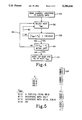
- FIG. 5 is a diagram illustrating the operation of the algorithm.
- FIG. 6 is a waveband diagram of a composite band with an FM sub-band bandfolded about 28 MHz.
- FIG. 1 A block diagram of a preferred implementation for the present invention is given in FIG. 1. It shows a multiple service digital receiver that is intended to simultaneously receive several channels of a given service, such as AM, FM, cellular, facsimile, computer, etc., or a number of channels from a combination of different services. In effect, a single piece of hardware functions as a number of independently operating receivers.
- the radio frequency spectrum is plotted along a vertical axis 2 on the left-hand side of the figure to illustrate some of the different types of services that can be accommodated.
- An antenna 4 which is preferably implemented as a collection of antenna elements with one antenna for each desired service, is mounted to the automobile or any other desired receiver facility.
- analog AM, FM and cellular bands are received and amplified by respective radio frequency (RF) amplifiers 6, 8 and 10.
- RF radio frequency
- the cellular service band of 865-895 MHz may be too large for convenient downstream digitization, it is preferably broken up into sub-bands that are switched on demand into a fixed region of the input bandwidth that is specifically allocated for cellular service.
- the cellular sub-bands are selected by changing a cellular local oscillator frequency, discussed below, in discrete steps. Multiple cellular voice channels can be handled without sub-band switching if the sub-band is wide enough to encompass all voice channels allocated. If the voice channels assigned are in different sub-bands, the sub-bands may be switched into the frequency band allocated for cellular voice by time division multiplexing. As illustrated, a cellular sub-band select switch 12 divides the cellular band into eight sub-bands of approximately 4 MHz each, plus a pair of 3 MHz guard bands at either end.
- the outputs of RF amplifiers 6, 8 and 10 are supplied respectively to mixers 14, 16 and 18, where they are respectively mixed with signals from local oscillators 20, 22 and 24.
- the frequency of each local oscillator is selected to translate its respective RF input to a restricted bandwidth base band that eliminates the large gaps between the original service bands.
- the FM band occupies about 20 MHz plus 4 MHz guard bands at either end
- AM occupies a band of about 3 MHz including guard bands
- a 4 MHz cellular sub-band requires 3 MHz guard bands at either end. This gives a total bandwidth of 41 MHz if the frequency gaps between the three service bands are eliminated.
- the FM oscillator 22 is set at 83.9 MHz
- the AM oscillator 20 is set at 111.9 MHz
- the cellular oscillator 24 is set at 114.9 MHz
- the three services will occupy the following adjacent bands (including guard bands):
- This continuous base band has a minimum Nyquist frequency of 41 MHz, which translates to a minimum analog-to-digital encoding rate of at least 82 megasamples per second.
- the FM service is set at the lower end of the composite band, cellular at the upper end and AM in the middle, the relative positions of the various service bands can be interchanged at will by appropriate selections of their respective oscillator frequencies.
- the AM band is preferably translated to the next lowest frequency portion of the composite waveband. Since AM service requires a substantial instantaneous dynamic range, it is translated towards the lower end of the input bandwidth where the number of analog-to-digital effective bits are the highest, and the (sin x)/x attenuation is low. Cellular service is placed within the remaining composite bandwidth.
- Local oscillators 20 and 24 for AM and cellular service are illustrated as fixed frequency oscillators, while local oscillator 22 for FM service is illustrated as an adjustable frequency oscillator.
- the frequency adjustment capability is part of the "bandfolding" feature. As discussed below, this feature could also be provided in connection with other services.
- the frequency-translated service bands produced by mixers 14, 16 and 18 are processed through analog filters 26, 28 and 30, respectively. These filters are conventional in design, and serve several functions. Bandpass RF filters are provided to reject out-of-band signals and noise power, such as the television channel 6 which is located just below the FM band. IF bandpass filters are provided to reject mixing images and local oscillator spurs. Lowpass and highpass filters employed for the AM service band can be efficiently and cost-effectively implemented with LC-type, or specialized active filters. For bandpass filters in the A/D input bandwidth, passive LC filters are preferred, while for high VHF and UHF, surface acoustic wave filters may be needed.
- the outputs of filters 26, 28 and 30 are transmitted through respective switches 32, 34 and 36 as a composite input to a single ADC 38, which digitizes the analog input and delivers it to a digital tuner 40.
- the tuner is controlled by the user(s) to select the desired AM and/or FM channels for listening, and/or a cellular channel. All of the channels for which the received signal exceeds a threshold level, indicating that the receiver is within the channel's service area (referred to hereinafter as "active channels"), including the user-selected channels, are provided to an F mix select circuit 42. This circuit selects the mixing frequency (F mix ) for the adjustable frequency oscillator 22 so as to establish a base frequency for the bandfolding waveband reduction.
- a scan circuit 44 When it is desired to scan through the FM band to locate a desired channel, a scan circuit 44 is actuated that momentarily interrupts the services supplied through switches 32, 34 and 36, and disables the FM bandfolding by adjusting the frequency of oscillator 22 so that it corresponds to one end of the FM band. In this manner the entire FM band is available for scanning. While the additional bandwidth reduction provided by the bandfolding technique is not used during a scanning mode, the temporary deletion of the AM and cellular bands leaves enough bandwidth available for the full FM service band.
- a digital filter 46, digital demodulator 48 and digital decoder 49 are provided downstream from the digital tuner 40 to process the selected digital signals and condition them for analog playback.
- a digital signal processor (DSP) is preferably used to implement these functions, as well as the F mix select function.
- DSP can implement filters of arbitrary shape factor, and lends itself to high performance demodulation and adaptive optimal detection algorithms. By selecting a DSP with a sufficiently high throughput, several narrowband signals can be demodulated concurrently. This results in the single hardware system of FIG. 1 providing the function of a number of independently operating receivers, which may be tuned to either separate service bands, or to multiple frequencies within a single service band.
- DAC digital-to-analog converter
- FIG. 2 illustrates a composite waveband that results from translating the FM and AM bands and the cellular sub-band to a substantially continuous portion of the frequency spectrum.
- the FM, AM and cellular service bands are shown translated to a composite service band which extends from DC up to 41 MHz. There are no significant gaps between the various service bands resulting in a significant reduction in both bandwidth and digitization requirements.
- a further substantial reduction in bandwidth can be achieved with a new bandfolding technique.
- active channel frequencies for a particular location are indicated by hatched bars 52. With a 20 MHz FM band and potential station locations each 200 KHz, a maximum of 100 stations can be accommodated. However, for any given location many of the channels will not be occupied by an active station. These empty channels are indicated by gaps G in FIG. 2 (the total number of channels has been reduced in FIG. 2 for simplification). Assuming that three different channels are selected simultaneously by three different users of the system, the selected channels are indicated by numerals F1, F2 and F3.
- the bandfolding technique described herein conserves bandwidth by actively determining the gap locations, and utilizing them to accommodate the selected stations F1, F2, F3.
- the bandfolding is accomplished by setting the mixing frequency of adjustable frequency oscillator 22 at an intermediate frequency within the FM band, rather than at 84 MHz or 112 MHz at one end or the other of the FM band (including guard bands).
- the exact FM mixing frequency is preferably selected to be at or near the middle of the band.
- the FM band in effect "folds over" the mixing frequency F mix , with the portion of the band below F mix superimposed over the portion above F mix . If F mix is selected to be the center of the FM band, the guard band at the lower end of the FM band will exactly overlap the guard band at the upper end after folding. To the extent that F mix is offset from the center of the FM band, the lower end of the band will be offset from the upper end by twice that amount after folding.
- FIG. 3 illustrates an example of the composite service bands after the FM band has been folded in this manner. Assume F mix has been selected at about the center of the FM band. After folding, F1, F2 and F3 are all located in gap locations on the opposite side of F mix . In this manner the FM bandwidth may be reduced to as little as half its unfolded level, assuming F mix is selected at about the middle of the band.
- the F mix select DSP 42 (FIG. 1) is programmed to select an F mix that produces a bandfolding without interference between the selected stations and other active stations, while ignoring interference between non-selected active stations.
- a summary flow diagram for the algorithm which it is programmed to perform is given in FIG. 4. Initially, the digitally encoded channel locations from ADC 38 are scanned to locate the gap frequencies (block 54). A tentative F mix is then selected (block 56). With the FM station locations at each odd tenth of a MHz (e.g. 87.9, 88.1, 88.3, etc.), F mix is chosen to be an even tenth of a MHz so that it will be positioned between channel locations. While the selection of a first tentative F mix is somewhat arbitrary, in the preferred embodiment either 97.0 or 98.8 MHz is selected because it is reasonably close to the center of the band.
- the tentative F mix is then compared with the selected station frequencies F 1 , F 2 , F 3 (collectively designated F j ) to see if it differs from the selected stations by more than 100 KHz (block 58). This frequency separation is desirable to minimize "1/f" noise (which varies inversely with the difference between a selected frequency and the local oscillator frequency), and to keep the selected station clear of the local oscillator frequency. If the F mix -F j differential is not greater than 100 KHz, the first tentative F mix is rejected and the system loops back along line 60 to block 56 to select the next tentative F mix (97.2 MHz follows 97.0; 98.6 MHz follows 98.8).
- each selected station frequency will fall within a gap in the folded waveband (block 64). This is accomplished by doubling F mix , and subtracting the frequencies of each of the selected stations F j in turn. If the result for any station does not coincide with a gap as determined in block 54, the system loops back along line 66 to select the next tentative F mix . If the result is positive for each selected channel (line 68), the tentative F mix is validated as a usable local oscillator frequency for the FM band. At this point the algorithm may either be stopped, or the validated F mix may be saved and the iterations continued to locate all of the usable F mixes (block 70).
- each channel frequency ending in 0.1, 0.3 or 0.5 MHz represents a gap, while the other channel frequencies ending in 0.7 or 0.9 MHz are occupied by active stations.
- the F j stations selected by the users are at 89.9, 96.9 and 98.7 MHz.
- the algorithm accordingly increments to the next tentative F mix at 97.6 MHz.
- This frequency satisfies the requirements for both spacing from selected stations, and a lack of interference between the selected and the non-selected active stations after the FM band has been folded about F mix . Accordingly, 97.6 MHz is identified as a suitable F mix for this particular pattern of active stations, gaps and selected stations for listening.
- FIG. 3 shows the results of bandfolding the FM spectrum of FIG. 2 about a particular F mix .
- the interferring active stations are indicated by crosshatched bars I. Since these stations are not being listened to, the interference does not detract from the users' reception.
- the active stations on one side of F mix that are located within gaps on the other side of F mix after bandfolding are indicated by single-hatched shading.
- the frequency locations of the station gaps are determined by scanning through each of the 100 possible station locations provided in digital format ADC 38. This scanning can be accomplished with a conventional DSP at about msec per station location, resulting in a total scan time of only about a fifth of a second. This is well within the comfort range of a listener who has just made a new station selection.
- the FM band can be translated to the upper end of the composite waveband and bandfolded in a manner analogous to that just described.
- the total composite bandwidth can be reduced to as little as about 27 or 28 MHz, including adequate guardbands for each of the three service bands.
- a further reduction in total bandwidth may be accomplished by bandfolding the cellular band in a similar manner.
- the invention is also applicable to other types of broadcast services, as mentioned above.
- band folding can be accomplished by using aliased images from a band pass or RF ADC, rather than by mixing with a base frequency.
- band folding can be accomplished by using aliased images from a band pass or RF ADC, rather than by mixing with a base frequency.
Abstract
Description
Claims (24)
Priority Applications (8)
| Application Number | Priority Date | Filing Date | Title |
|---|---|---|---|
| US07/714,494 US5280636A (en) | 1991-06-13 | 1991-06-13 | Multi-band digital receiving apparatus and method with bandwidth reduction |
| CA002173376A CA2173376C (en) | 1991-06-13 | 1992-04-30 | Multi-band digital receiving apparatus and method with bandwidth reduction |
| CA002067652A CA2067652C (en) | 1991-06-13 | 1992-04-30 | Multi-band digital receiving apparatus and method with bandwidth reduction |
| CA002173377A CA2173377C (en) | 1991-06-13 | 1992-04-30 | Multi-band digital receiving apparatus and method with bandwidth reduction |
| GB9517339A GB2290429B (en) | 1991-06-13 | 1992-05-29 | Multi-band digital receiving apparatus and method with bandwidth reduction |
| GB9211439A GB2258359B (en) | 1991-06-13 | 1992-05-29 | Multi-band digital receiving apparatus and method with bandwidth reduction |
| DE4219361A DE4219361C2 (en) | 1991-06-13 | 1992-06-12 | Method for reducing the bandwidth of a frequency band and receiver for receiving a large number of message signals at the same time |
| JP4155351A JP2685387B2 (en) | 1991-06-13 | 1992-06-15 | Multi-band digital receiver with reduced bandwidth and method thereof |
Applications Claiming Priority (1)
| Application Number | Priority Date | Filing Date | Title |
|---|---|---|---|
| US07/714,494 US5280636A (en) | 1991-06-13 | 1991-06-13 | Multi-band digital receiving apparatus and method with bandwidth reduction |
Publications (1)
| Publication Number | Publication Date |
|---|---|
| US5280636A true US5280636A (en) | 1994-01-18 |
Family
ID=24870274
Family Applications (1)
| Application Number | Title | Priority Date | Filing Date |
|---|---|---|---|
| US07/714,494 Expired - Lifetime US5280636A (en) | 1991-06-13 | 1991-06-13 | Multi-band digital receiving apparatus and method with bandwidth reduction |
Country Status (5)
| Country | Link |
|---|---|
| US (1) | US5280636A (en) |
| JP (1) | JP2685387B2 (en) |
| CA (1) | CA2067652C (en) |
| DE (1) | DE4219361C2 (en) |
| GB (1) | GB2258359B (en) |
Cited By (61)
| Publication number | Priority date | Publication date | Assignee | Title |
|---|---|---|---|---|
| US5412690A (en) * | 1993-03-08 | 1995-05-02 | Motorola, Inc. | Method and apparatus for receiving electromagnetic radiation within a frequency band |
| WO1996021280A1 (en) * | 1994-12-29 | 1996-07-11 | Motorola Inc. | Split frequency band signal digitizer and method |
| US5548839A (en) * | 1994-10-14 | 1996-08-20 | Caldwell; Stephen P. | Wide band radio-frequency converter having multiple use of intermediate frequency translators |
| US5584056A (en) * | 1994-10-17 | 1996-12-10 | Hyundai Electronics Industrial Co., Ltd. | Dual-bandwidth cellular telephone switching apparatus |
| US5634203A (en) * | 1994-09-02 | 1997-05-27 | Motorola Inc. | Adaptive multi-receiver shared antenna matching system and method |
| US5640694A (en) * | 1995-05-03 | 1997-06-17 | Northrop Grumman Corporation | Integrated RF system with segmented frequency conversion |
| EP0813312A2 (en) * | 1996-06-10 | 1997-12-17 | Matsushita Electric Industrial Co., Ltd. | Multiband mobile unit communication apparatus |
| US5852784A (en) * | 1996-04-08 | 1998-12-22 | Matsushita Electric Industrial Co., Ltd. | Multiband mobile unit communication apparatus |
| US5870402A (en) * | 1991-06-13 | 1999-02-09 | Raytheon Company | Multiple user digital receiver apparatus and method with time division multiplexing |
| US5915223A (en) * | 1996-02-21 | 1999-06-22 | U.S. Philips Corporation | Multimode radiotelephone |
| US5999824A (en) * | 1996-12-06 | 1999-12-07 | Samsung Electronics Co., Ltd. | Radio signal processing apparatus of portable telephone for sharing digital/analog compatible mode and personal communication service mode |
| WO1999066646A1 (en) * | 1998-06-18 | 1999-12-23 | Telefonaktiebolaget Lm Ericsson | Radio receiver |
| US6029052A (en) * | 1997-07-01 | 2000-02-22 | Telefonaktiebolaget Lm Ericsson | Multiple-mode direct conversion receiver |
| US6052569A (en) * | 1997-01-17 | 2000-04-18 | U.S. Philips Corporation | Radio receiver having a first tuner circuit for receiving signals in a first and a second frequency range, and a second tuner circuit for receiving signals in the first and a third frequency range |
| US6064665A (en) * | 1997-10-22 | 2000-05-16 | U S West, Inc. | System and method for single to two-band personal communication service base station conversion |
| US6091963A (en) * | 1997-01-21 | 2000-07-18 | Telefonaktiebolaget Lm Ericsson | Multi-frequency band receiver for RF signal |
| US6163683A (en) * | 1999-02-24 | 2000-12-19 | International Business Machines Corporation | Broadcast data radio system and receiver apparatus therefor |
| FR2801152A1 (en) * | 1999-11-11 | 2001-05-18 | Bosch Gmbh Robert | Car radio installation tuner commands having user request passed for radio information unit tuner services and assigned values setting tuners dynamically/following available tuners. |
| US6240281B1 (en) * | 1997-06-17 | 2001-05-29 | Thomson Licensing S.A. | Command protocol for circuits used for receiving microwave signals and device implementing the protocol |
| US6259902B1 (en) * | 1998-10-29 | 2001-07-10 | Motorola, Inc. | Dual channel superheterodyne receiver |
| EP1154589A2 (en) * | 2000-04-14 | 2001-11-14 | Lucent Technologies Inc. | Multiple branch receiver system and method |
| WO2002011294A2 (en) * | 2000-07-31 | 2002-02-07 | Radical Horizon, Inc. | Multi-protocol receiver |
| US6442382B1 (en) * | 1997-06-27 | 2002-08-27 | Agere Systems Guardian Corp. | Filter switching system and method |
| US20020187762A1 (en) * | 2001-06-06 | 2002-12-12 | Whikehart J. William | Method and system for multi-channel RF digitization with analog selectivity |
| KR100381781B1 (en) * | 2001-01-22 | 2003-04-26 | 삼성에스디에스 주식회사 | Electronic toll collection system |
| US6678512B1 (en) * | 2000-04-14 | 2004-01-13 | Lucent Technologies Inc. | Receiver system using analog to digital conversion at radio frequency and method |
| US20040017306A1 (en) * | 2002-07-23 | 2004-01-29 | Miao George J. | Scalable analog-to-digital converter with digital down conversion for ultra wideband communications |
| US6741847B1 (en) * | 2000-06-28 | 2004-05-25 | Northrop Grumman Corporation | Multi-carrier receiver frequency conversion architecture |
| US20040205820A1 (en) * | 2003-04-14 | 2004-10-14 | Ramin Khoini-Poorfard | Receiver architectures utilizing coarse analog tuning and associated methods |
| US20050037720A1 (en) * | 2003-08-11 | 2005-02-17 | Schick Technologies, Inc. | Method for achieving immediate and accurate automatic frequency tuning |
| US6944475B1 (en) * | 2000-08-30 | 2005-09-13 | Northrop Grumman Corporation | Transceiver-processor building block for electronic radio systems |
| US20050233765A1 (en) * | 2004-04-16 | 2005-10-20 | Sanders Stuart B | Low cost method for receiving broadcast channels with a cellular terminal |
| US20060227898A1 (en) * | 2003-07-10 | 2006-10-12 | Gibson Timothy P | Radio receiver |
| US20070015457A1 (en) * | 2004-10-27 | 2007-01-18 | Krampf Steven S | Entertainment system with bandless tuning, remote control, alarm and universal docking |
| EP1777948A2 (en) * | 2005-10-20 | 2007-04-25 | Samsung Electronics Co., Ltd. | Receiver without phase locked loop frequency synthesizer and receiving method using the same |
| EP1790085A1 (en) * | 2004-06-08 | 2007-05-30 | THOMSON Licensing | Apparatus and method for processing signals in a multi-channel receiver |
| US20080037687A1 (en) * | 2006-08-11 | 2008-02-14 | Mediatek Inc. | Method of direct rf digitization for multiple gnss system bands and receiver using the same |
| US20080084861A1 (en) * | 2006-10-10 | 2008-04-10 | Honeywell International Inc. | Avionics communication system and method utilizing multi-channel radio technology and a shared data bus |
| US20080163049A1 (en) * | 2004-10-27 | 2008-07-03 | Steven Krampf | Entertainment system with unified content selection |
| US20080233883A1 (en) * | 2007-03-19 | 2008-09-25 | Brima Ibrahim | Method And System For Detecting Channels Suitable For FM Transmission In An Integrated FM Transmit/Receive System |
| US20080248770A1 (en) * | 2007-04-05 | 2008-10-09 | Schultz Micha | Broadband reception system |
| US20080299925A1 (en) * | 2007-05-30 | 2008-12-04 | John Stuart Walley | Method And System For Processing Channels In A FM Communication System |
| US20080298519A1 (en) * | 2005-11-21 | 2008-12-04 | Fujitsu Ten Limited | Receiver Device |
| US20090017777A1 (en) * | 2007-07-13 | 2009-01-15 | Honeywell International Inc. | Reconfigurable aircraft radio communications system |
| WO2009021247A1 (en) * | 2008-09-03 | 2009-02-12 | Phybit Pte. Ltd. | Methods and system for multi-service multi-band radio signal channelizer |
| US20090298451A1 (en) * | 2008-05-29 | 2009-12-03 | Honeywell International Inc. | Reconfigurable aircraft communications system with integrated avionics communication router and audio management functions |
| EP2134124A1 (en) | 2008-06-13 | 2009-12-16 | Research In Motion Limited | Method and apparatus for storing and for reading frequency values modified to be compatible with a parameter storage area |
| US20090311983A1 (en) * | 2008-06-13 | 2009-12-17 | Andrew Farnsworth | Method and Apparatus for Storing Frequencies |
| WO2010095083A1 (en) | 2009-02-18 | 2010-08-26 | Technion Research & Development Foundation Ltd | Efficient sampling and reconstruction of sparse multi-band signals |
| US20110128999A1 (en) * | 2008-06-04 | 2011-06-02 | Alexander Ruegamer | Multi-Frequency Band Receiver |
| US20120040628A1 (en) * | 2010-08-13 | 2012-02-16 | Infineon Technologies Ag | Transceiver with Interferer Control |
| US8340047B2 (en) | 2007-05-25 | 2012-12-25 | Fujitsu Ten Limited | Integrated antenna device, integrated demodulating device, and integrated receiving device |
| US8711993B2 (en) | 2010-12-10 | 2014-04-29 | Honeywell International Inc. | Wideband multi-channel receiver with fixed-frequency notch filter for interference rejection |
| US20150156444A1 (en) * | 2009-04-17 | 2015-06-04 | Maxlinear, Inc. | Wideband tuner architecture |
| US9143194B2 (en) | 2010-03-14 | 2015-09-22 | Technion Research & Development Foundation Ltd. | Low-rate sampling of pulse streams |
| CN105099471A (en) * | 2015-07-16 | 2015-11-25 | 中国电子科技集团公司第三十六研究所 | Method and digital receiver for processing a plurality of sparse bandwidth signals |
| US9614629B2 (en) | 2012-08-15 | 2017-04-04 | Commscope Technologies Llc | Telecommunication system using multiple Nyquist zone operations |
| US20190179032A1 (en) * | 2017-12-13 | 2019-06-13 | The Regents Of The University Of Michigan | Quadrature fully-integrated tri-band gps receiver |
| US11126397B2 (en) | 2004-10-27 | 2021-09-21 | Chestnut Hill Sound, Inc. | Music audio control and distribution system in a location |
| US11228328B1 (en) * | 2021-03-15 | 2022-01-18 | SiTune Corporation | Integrated radio frequency transceiver |
| US11804862B2 (en) | 2021-09-30 | 2023-10-31 | Silicon Laboratories Inc. | Dual-band operation of a radio device |
Families Citing this family (7)
| Publication number | Priority date | Publication date | Assignee | Title |
|---|---|---|---|---|
| DE4329010A1 (en) * | 1993-08-28 | 1995-03-02 | Sel Alcatel Ag | Radio system |
| ES2206601T5 (en) | 1995-10-09 | 2011-06-06 | Snaptrack, Inc. | COMBINED GPS POSITION AND COMMUNICATIONS SYSTEM USING SHARED CIRCUITS. |
| DE19823235A1 (en) * | 1998-05-25 | 1999-12-02 | Abb Research Ltd | Method for multichannel transmission over a given bandwidth |
| GB0030965D0 (en) | 2000-12-19 | 2001-01-31 | Nokia Oy Ab | Improvements relating to satellite reception` |
| JP2007288257A (en) * | 2006-04-12 | 2007-11-01 | Fujitsu Ten Ltd | Reception system |
| ITRM20080688A1 (en) * | 2008-12-20 | 2010-06-21 | Livio Conti | METHOD A FEEDBACK VARIABLE CONDITIONING OF SIGNALS AND ITS RELATED SYSTEM OF ACQUISITION, SPECTRAL ANALYSIS AND DIGITAL DATA MANAGEMENT |
| DE102013218201A1 (en) * | 2013-09-11 | 2015-03-12 | Volkswagen Aktiengesellschaft | Method and device for receiving signals |
Citations (6)
| Publication number | Priority date | Publication date | Assignee | Title |
|---|---|---|---|---|
| JPS5552642A (en) * | 1978-10-12 | 1980-04-17 | Sanyo Electric Co Ltd | Tuner unit of television receiver |
| JPS62230228A (en) * | 1986-03-31 | 1987-10-08 | Toshiba Corp | Two-frequency band reception system |
| US4853944A (en) * | 1988-03-10 | 1989-08-01 | Allied-Signal Inc. | Digital AM/FM/φM demodulator |
| US4881272A (en) * | 1987-03-30 | 1989-11-14 | Kabushiki Kaisha Toshiba | Multi-band FM receiver for receiving FM broadcasting signals and TV broadcasting sound signals |
| US5027430A (en) * | 1987-07-24 | 1991-06-25 | Sharp Kabushiki Kaisha | Outdoor unit low noise converter for satellite broadcast reception use |
| US5058107A (en) * | 1989-01-05 | 1991-10-15 | Hughes Aircraft Company | Efficient digital frequency division multiplexed signal receiver |
Family Cites Families (8)
| Publication number | Priority date | Publication date | Assignee | Title |
|---|---|---|---|---|
| US642344A (en) * | 1899-11-04 | 1900-01-30 | Jacob Rosenberg | Machine for cementing together parts of waterproof garments. |
| GB642344A (en) * | 1945-11-27 | 1950-08-30 | Director | Improvements in or relating to radio receiving apparatus |
| JPS4971807A (en) * | 1972-11-11 | 1974-07-11 | ||
| JPS5220086B2 (en) * | 1972-11-11 | 1977-06-01 | ||
| US4135158A (en) * | 1975-06-02 | 1979-01-16 | Motorola, Inc. | Universal automotive electronic radio |
| US4521646A (en) * | 1980-06-26 | 1985-06-04 | Callaghan Edward P | Methods and apparatus for bandwidth reduction |
| US4884265A (en) * | 1987-04-30 | 1989-11-28 | Loral Corporation | Digital demodulator for frequency-division-multiplexed signals |
| JPH04223631A (en) * | 1990-12-25 | 1992-08-13 | Nippon Telegr & Teleph Corp <Ntt> | Multiple channel tuner |
-
1991
- 1991-06-13 US US07/714,494 patent/US5280636A/en not_active Expired - Lifetime
-
1992
- 1992-04-30 CA CA002067652A patent/CA2067652C/en not_active Expired - Lifetime
- 1992-05-29 GB GB9211439A patent/GB2258359B/en not_active Expired - Lifetime
- 1992-06-12 DE DE4219361A patent/DE4219361C2/en not_active Expired - Lifetime
- 1992-06-15 JP JP4155351A patent/JP2685387B2/en not_active Expired - Lifetime
Patent Citations (6)
| Publication number | Priority date | Publication date | Assignee | Title |
|---|---|---|---|---|
| JPS5552642A (en) * | 1978-10-12 | 1980-04-17 | Sanyo Electric Co Ltd | Tuner unit of television receiver |
| JPS62230228A (en) * | 1986-03-31 | 1987-10-08 | Toshiba Corp | Two-frequency band reception system |
| US4881272A (en) * | 1987-03-30 | 1989-11-14 | Kabushiki Kaisha Toshiba | Multi-band FM receiver for receiving FM broadcasting signals and TV broadcasting sound signals |
| US5027430A (en) * | 1987-07-24 | 1991-06-25 | Sharp Kabushiki Kaisha | Outdoor unit low noise converter for satellite broadcast reception use |
| US4853944A (en) * | 1988-03-10 | 1989-08-01 | Allied-Signal Inc. | Digital AM/FM/φM demodulator |
| US5058107A (en) * | 1989-01-05 | 1991-10-15 | Hughes Aircraft Company | Efficient digital frequency division multiplexed signal receiver |
Cited By (138)
| Publication number | Priority date | Publication date | Assignee | Title |
|---|---|---|---|---|
| US5870402A (en) * | 1991-06-13 | 1999-02-09 | Raytheon Company | Multiple user digital receiver apparatus and method with time division multiplexing |
| US5412690A (en) * | 1993-03-08 | 1995-05-02 | Motorola, Inc. | Method and apparatus for receiving electromagnetic radiation within a frequency band |
| US5634203A (en) * | 1994-09-02 | 1997-05-27 | Motorola Inc. | Adaptive multi-receiver shared antenna matching system and method |
| US5548839A (en) * | 1994-10-14 | 1996-08-20 | Caldwell; Stephen P. | Wide band radio-frequency converter having multiple use of intermediate frequency translators |
| AU692642B2 (en) * | 1994-10-14 | 1998-06-11 | Gec-Marconi Electronic Systems Corporation | Wide band radio-frequency converter having multiple use of intermediate frequency translators |
| US5584056A (en) * | 1994-10-17 | 1996-12-10 | Hyundai Electronics Industrial Co., Ltd. | Dual-bandwidth cellular telephone switching apparatus |
| GB2301500A (en) * | 1994-12-29 | 1996-12-04 | Motorola Inc | Split frequency band signal digitizer and method |
| DE19581508T1 (en) * | 1994-12-29 | 1997-08-21 | Motorola Inc | Digitizer for a split frequency band signal and method therefor |
| US5668836A (en) * | 1994-12-29 | 1997-09-16 | Motorola, Inc. | Split frequency band signal digitizer and method |
| GB2301500B (en) * | 1994-12-29 | 1998-07-01 | Motorola Inc | Split frequency band signal digitizer and method |
| CN1057413C (en) * | 1994-12-29 | 2000-10-11 | 摩托罗拉公司 | Frequency band separation signal digitizer and method thereof |
| WO1996021280A1 (en) * | 1994-12-29 | 1996-07-11 | Motorola Inc. | Split frequency band signal digitizer and method |
| US5640694A (en) * | 1995-05-03 | 1997-06-17 | Northrop Grumman Corporation | Integrated RF system with segmented frequency conversion |
| US5915223A (en) * | 1996-02-21 | 1999-06-22 | U.S. Philips Corporation | Multimode radiotelephone |
| US5852784A (en) * | 1996-04-08 | 1998-12-22 | Matsushita Electric Industrial Co., Ltd. | Multiband mobile unit communication apparatus |
| US6014571A (en) * | 1996-06-10 | 2000-01-11 | Matsushita Electric Industrial Co., Ltd. | Multiband mobile unit communication apparatus |
| EP0813312A3 (en) * | 1996-06-10 | 2000-01-26 | Matsushita Electric Industrial Co., Ltd. | Multiband mobile unit communication apparatus |
| EP0813312A2 (en) * | 1996-06-10 | 1997-12-17 | Matsushita Electric Industrial Co., Ltd. | Multiband mobile unit communication apparatus |
| US5999824A (en) * | 1996-12-06 | 1999-12-07 | Samsung Electronics Co., Ltd. | Radio signal processing apparatus of portable telephone for sharing digital/analog compatible mode and personal communication service mode |
| US6052569A (en) * | 1997-01-17 | 2000-04-18 | U.S. Philips Corporation | Radio receiver having a first tuner circuit for receiving signals in a first and a second frequency range, and a second tuner circuit for receiving signals in the first and a third frequency range |
| US6091963A (en) * | 1997-01-21 | 2000-07-18 | Telefonaktiebolaget Lm Ericsson | Multi-frequency band receiver for RF signal |
| US6240281B1 (en) * | 1997-06-17 | 2001-05-29 | Thomson Licensing S.A. | Command protocol for circuits used for receiving microwave signals and device implementing the protocol |
| US6442382B1 (en) * | 1997-06-27 | 2002-08-27 | Agere Systems Guardian Corp. | Filter switching system and method |
| US20090239493A1 (en) * | 1997-06-27 | 2009-09-24 | Agere Systems Inc. | Filter Switching System and Method |
| US7885624B2 (en) | 1997-06-27 | 2011-02-08 | Agere Systems Inc. | Filter switching system and method |
| US6029052A (en) * | 1997-07-01 | 2000-02-22 | Telefonaktiebolaget Lm Ericsson | Multiple-mode direct conversion receiver |
| US6064665A (en) * | 1997-10-22 | 2000-05-16 | U S West, Inc. | System and method for single to two-band personal communication service base station conversion |
| WO1999066646A1 (en) * | 1998-06-18 | 1999-12-23 | Telefonaktiebolaget Lm Ericsson | Radio receiver |
| US6922449B1 (en) * | 1998-06-18 | 2005-07-26 | Telefonaktiebolaget L M Ericsson (Publ) | Radio receiver |
| AU753711B2 (en) * | 1998-06-18 | 2002-10-24 | Telefonaktiebolaget Lm Ericsson (Publ) | Radio receiver |
| US6259902B1 (en) * | 1998-10-29 | 2001-07-10 | Motorola, Inc. | Dual channel superheterodyne receiver |
| US6163683A (en) * | 1999-02-24 | 2000-12-19 | International Business Machines Corporation | Broadcast data radio system and receiver apparatus therefor |
| DE19954281A1 (en) * | 1999-11-11 | 2001-06-07 | Bosch Gmbh Robert | Method and device for controlling a radio device with several tuner devices |
| DE19954281C2 (en) * | 1999-11-11 | 2003-06-18 | Bosch Gmbh Robert | Method and device for controlling a radio device with several tuner devices |
| FR2801152A1 (en) * | 1999-11-11 | 2001-05-18 | Bosch Gmbh Robert | Car radio installation tuner commands having user request passed for radio information unit tuner services and assigned values setting tuners dynamically/following available tuners. |
| EP1154589A2 (en) * | 2000-04-14 | 2001-11-14 | Lucent Technologies Inc. | Multiple branch receiver system and method |
| US6678512B1 (en) * | 2000-04-14 | 2004-01-13 | Lucent Technologies Inc. | Receiver system using analog to digital conversion at radio frequency and method |
| US6574459B1 (en) | 2000-04-14 | 2003-06-03 | Lucent Technologies Inc. | Multiple branch receiver system and method |
| EP1154589A3 (en) * | 2000-04-14 | 2001-12-05 | Lucent Technologies Inc. | Multiple branch receiver system and method |
| US6741847B1 (en) * | 2000-06-28 | 2004-05-25 | Northrop Grumman Corporation | Multi-carrier receiver frequency conversion architecture |
| WO2002011294A2 (en) * | 2000-07-31 | 2002-02-07 | Radical Horizon, Inc. | Multi-protocol receiver |
| US6914950B1 (en) | 2000-07-31 | 2005-07-05 | Lyrtech Inc. | Multi-protocol receiver |
| WO2002011294A3 (en) * | 2000-07-31 | 2002-09-19 | Isaac Newton Technologies | Multi-protocol receiver |
| US6944475B1 (en) * | 2000-08-30 | 2005-09-13 | Northrop Grumman Corporation | Transceiver-processor building block for electronic radio systems |
| KR100381781B1 (en) * | 2001-01-22 | 2003-04-26 | 삼성에스디에스 주식회사 | Electronic toll collection system |
| US20020187762A1 (en) * | 2001-06-06 | 2002-12-12 | Whikehart J. William | Method and system for multi-channel RF digitization with analog selectivity |
| US7200377B2 (en) | 2001-06-06 | 2007-04-03 | Visteon Corporation | Method and system for multi-channel RF digitization with analog selectivity |
| US6744832B2 (en) * | 2002-07-23 | 2004-06-01 | George J. Miao | Analog-to-digital converter bank based ultra wideband communications |
| US20040017306A1 (en) * | 2002-07-23 | 2004-01-29 | Miao George J. | Scalable analog-to-digital converter with digital down conversion for ultra wideband communications |
| US7904040B2 (en) | 2003-04-14 | 2011-03-08 | Silicon Laboratories, Inc. | Receiver architectures utilizing coarse analog tuning and associated methods |
| US20040205820A1 (en) * | 2003-04-14 | 2004-10-14 | Ramin Khoini-Poorfard | Receiver architectures utilizing coarse analog tuning and associated methods |
| US20040205819A1 (en) * | 2003-04-14 | 2004-10-14 | Ramin Khoini-Poorfard | Integrated multi-tuner satellite receiver architecture and associated method |
| US20080250460A1 (en) * | 2003-04-14 | 2008-10-09 | Silicon Laboratories Inc. | Receiver architectures utilizing coarse analog tuning and associated methods |
| US7340230B2 (en) * | 2003-04-14 | 2008-03-04 | Silicon Laboratories Inc. | Receiver architectures utilizing coarse analog tuning and associated methods |
| US7167694B2 (en) | 2003-04-14 | 2007-01-23 | Silicon Laboratories Inc. | Integrated multi-tuner satellite receiver architecture and associated method |
| US20060227898A1 (en) * | 2003-07-10 | 2006-10-12 | Gibson Timothy P | Radio receiver |
| US20050037720A1 (en) * | 2003-08-11 | 2005-02-17 | Schick Technologies, Inc. | Method for achieving immediate and accurate automatic frequency tuning |
| WO2005020645A3 (en) * | 2003-08-11 | 2006-03-09 | Schick Technologies Inc | Method for achieving immediate and accurate automatic frequency tuning |
| US7171181B2 (en) * | 2003-08-11 | 2007-01-30 | Schick Technologies, Inc. | Method for achieving immediate and accurate automatic frequency tuning |
| WO2005020645A2 (en) * | 2003-08-11 | 2005-03-03 | Schick Technologies, Inc. | Method for achieving immediate and accurate automatic frequency tuning |
| US8000675B2 (en) | 2004-04-16 | 2011-08-16 | Sony Ericsson Mobile Communications Ab | Low cost method for receiving broadcast channels with a cellular terminal |
| US20050233765A1 (en) * | 2004-04-16 | 2005-10-20 | Sanders Stuart B | Low cost method for receiving broadcast channels with a cellular terminal |
| WO2005119925A1 (en) * | 2004-04-16 | 2005-12-15 | Sony Ericsson Mobile Communications Ab | A low cost method for receiving broadcast channels with a cellular terminal |
| EP1790085A1 (en) * | 2004-06-08 | 2007-05-30 | THOMSON Licensing | Apparatus and method for processing signals in a multi-channel receiver |
| US20070242158A1 (en) * | 2004-06-08 | 2007-10-18 | Pugel Michael A | Apparatus and Method for Processing Signals in a Multi-Channel Receiver |
| US20110070777A1 (en) * | 2004-10-27 | 2011-03-24 | Chestnut Hill Sound, Inc. | Electrical connector adaptor system for media devices |
| US20110070757A1 (en) * | 2004-10-27 | 2011-03-24 | Chestnut Hill Sound, Inc. | Electrical and mechanical connector adaptor system for media devices |
| US20080163049A1 (en) * | 2004-10-27 | 2008-07-03 | Steven Krampf | Entertainment system with unified content selection |
| US20110072347A1 (en) * | 2004-10-27 | 2011-03-24 | Chestnut Hill Sound, Inc. | Entertainment system with remote control |
| US11126397B2 (en) | 2004-10-27 | 2021-09-21 | Chestnut Hill Sound, Inc. | Music audio control and distribution system in a location |
| US20110071658A1 (en) * | 2004-10-27 | 2011-03-24 | Chestnut Hill Sound, Inc. | Media appliance with docking |
| US10114608B2 (en) | 2004-10-27 | 2018-10-30 | Chestnut Hill Sound, Inc. | Multi-mode media device operable in first and second modes, selectively |
| US8843092B2 (en) | 2004-10-27 | 2014-09-23 | Chestnut Hill Sound, Inc. | Method and apparatus for accessing media content via metadata |
| US20070015457A1 (en) * | 2004-10-27 | 2007-01-18 | Krampf Steven S | Entertainment system with bandless tuning, remote control, alarm and universal docking |
| US8725063B2 (en) | 2004-10-27 | 2014-05-13 | Chestnut Hill Sound, Inc. | Multi-mode media device using metadata to access media content |
| US8655303B2 (en) | 2004-10-27 | 2014-02-18 | Chestnut Hill Sound, Inc. | Entertainment system with sourceless selection including playlists |
| US8355690B2 (en) | 2004-10-27 | 2013-01-15 | Chestnut Hill Sound, Inc. | Electrical and mechanical connector adaptor system for media devices |
| US20110069433A1 (en) * | 2004-10-27 | 2011-03-24 | Chestnut Hill Sound, Inc. | Media appliance with auxiliary source module |
| US8195114B2 (en) | 2004-10-27 | 2012-06-05 | Chestnut Hill Sound, Inc. | Entertainment system with bandless content selection |
| US8090309B2 (en) | 2004-10-27 | 2012-01-03 | Chestnut Hill Sound, Inc. | Entertainment system with unified content selection |
| US20110070853A1 (en) * | 2004-10-27 | 2011-03-24 | Steven Krampf | Entertainment system with bandless selection including playlists |
| US7885622B2 (en) | 2004-10-27 | 2011-02-08 | Chestnut Hill Sound Inc. | Entertainment system with bandless tuning |
| US20110069844A1 (en) * | 2004-10-27 | 2011-03-24 | Krampf Steven S | Entertainment system with bandless content selection |
| US20110072050A1 (en) * | 2004-10-27 | 2011-03-24 | Chestnut Hill Sound, Inc. | Accessing digital media content via metadata |
| US20070091212A1 (en) * | 2005-10-20 | 2007-04-26 | Samsung Electronics Co., Ltd. | Receiver without phase locked loop frequency synthesizer and receiving method using the same |
| US7907922B2 (en) * | 2005-10-20 | 2011-03-15 | Samsung Electronics Co., Ltd. | Receiver without phase locked loop frequency synthesizer and receiving method using the same |
| EP1777948A3 (en) * | 2005-10-20 | 2011-10-12 | Samsung Electronics Co., Ltd. | Receiver without phase locked loop frequency synthesizer and receiving method using the same |
| EP1777948A2 (en) * | 2005-10-20 | 2007-04-25 | Samsung Electronics Co., Ltd. | Receiver without phase locked loop frequency synthesizer and receiving method using the same |
| US20080298519A1 (en) * | 2005-11-21 | 2008-12-04 | Fujitsu Ten Limited | Receiver Device |
| US20080037687A1 (en) * | 2006-08-11 | 2008-02-14 | Mediatek Inc. | Method of direct rf digitization for multiple gnss system bands and receiver using the same |
| US7720178B2 (en) * | 2006-08-11 | 2010-05-18 | Mediatek Inc. | Method of direct RF digitization for multiple GNSS system bands and receiver using the same |
| CN101123440B (en) * | 2006-08-11 | 2011-04-06 | 联发科技股份有限公司 | Method of direct RF digitization for multiple gnss system bands and receiver using the same |
| US20080084861A1 (en) * | 2006-10-10 | 2008-04-10 | Honeywell International Inc. | Avionics communication system and method utilizing multi-channel radio technology and a shared data bus |
| US8027641B2 (en) | 2007-03-19 | 2011-09-27 | Broadcom Corporation | Method and system for detecting channels suitable for FM transmission in an integrated FM transmit/receive system |
| US20080233883A1 (en) * | 2007-03-19 | 2008-09-25 | Brima Ibrahim | Method And System For Detecting Channels Suitable For FM Transmission In An Integrated FM Transmit/Receive System |
| US20080248770A1 (en) * | 2007-04-05 | 2008-10-09 | Schultz Micha | Broadband reception system |
| US8340047B2 (en) | 2007-05-25 | 2012-12-25 | Fujitsu Ten Limited | Integrated antenna device, integrated demodulating device, and integrated receiving device |
| US7869779B2 (en) * | 2007-05-30 | 2011-01-11 | Broadcom Corporation | Method and system for processing channels in a FM communication system |
| US20080299925A1 (en) * | 2007-05-30 | 2008-12-04 | John Stuart Walley | Method And System For Processing Channels In A FM Communication System |
| US8081933B2 (en) | 2007-07-13 | 2011-12-20 | Honeywell International Inc. | Reconfigurable aircraft radio communications system |
| US20090017777A1 (en) * | 2007-07-13 | 2009-01-15 | Honeywell International Inc. | Reconfigurable aircraft radio communications system |
| US20090298451A1 (en) * | 2008-05-29 | 2009-12-03 | Honeywell International Inc. | Reconfigurable aircraft communications system with integrated avionics communication router and audio management functions |
| US8019338B2 (en) | 2008-05-29 | 2011-09-13 | Honeywell International Inc. | Reconfigurable aircraft communications system with integrated avionics communication router and audio management functions |
| US20110128999A1 (en) * | 2008-06-04 | 2011-06-02 | Alexander Ruegamer | Multi-Frequency Band Receiver |
| US8306154B2 (en) * | 2008-06-04 | 2012-11-06 | Fraunhofer-Gesellschaft Zur Foerderung Der Angewandten Forschung E.V. | Multi-frequency band receiver |
| US20090311983A1 (en) * | 2008-06-13 | 2009-12-17 | Andrew Farnsworth | Method and Apparatus for Storing Frequencies |
| US8532593B2 (en) | 2008-06-13 | 2013-09-10 | Blackberry Limited | Method and apparatus for storing frequencies |
| EP2134124A1 (en) | 2008-06-13 | 2009-12-16 | Research In Motion Limited | Method and apparatus for storing and for reading frequency values modified to be compatible with a parameter storage area |
| WO2009021247A1 (en) * | 2008-09-03 | 2009-02-12 | Phybit Pte. Ltd. | Methods and system for multi-service multi-band radio signal channelizer |
| WO2010095083A1 (en) | 2009-02-18 | 2010-08-26 | Technion Research & Development Foundation Ltd | Efficient sampling and reconstruction of sparse multi-band signals |
| EP2399342A1 (en) * | 2009-02-18 | 2011-12-28 | Technion Research and Development Foundation, Ltd. | Efficient sampling and reconstruction of sparse multi-band signals |
| EP2399342A4 (en) * | 2009-02-18 | 2015-04-01 | Technion Res & Dev Foundation | Efficient sampling and reconstruction of sparse multi-band signals |
| US9210363B2 (en) * | 2009-04-17 | 2015-12-08 | Maxlinear, Inc. | Wideband tuner architecture |
| US20150156444A1 (en) * | 2009-04-17 | 2015-06-04 | Maxlinear, Inc. | Wideband tuner architecture |
| US20150156535A1 (en) * | 2009-04-17 | 2015-06-04 | Maxlinear, Inc. | Wideband tuner architecture |
| US11381866B2 (en) | 2009-04-17 | 2022-07-05 | Entropic Communications, Llc | Cable television device |
| US11399206B2 (en) | 2009-04-17 | 2022-07-26 | Entropic Communications, Llc | Method for receiving a television signal |
| US9210362B2 (en) * | 2009-04-17 | 2015-12-08 | Maxlinear, Inc. | Wideband tuner architecture |
| US10972781B2 (en) | 2009-04-17 | 2021-04-06 | Maxlinear, Inc. | Wideband tuner architecture |
| US11490152B1 (en) | 2009-04-17 | 2022-11-01 | Entropic Communications, Llc | System and method for receiving a television signal |
| US11785275B2 (en) | 2009-04-17 | 2023-10-10 | Entropic Communications, Llc | System and method for receiving a television signal |
| US11516535B2 (en) | 2009-04-17 | 2022-11-29 | Entropic Communications, Llc | System and method for receiving a television signal |
| US10313733B2 (en) | 2009-04-17 | 2019-06-04 | Maxlinear, Inc. | Wideband tuner architecture |
| US9143194B2 (en) | 2010-03-14 | 2015-09-22 | Technion Research & Development Foundation Ltd. | Low-rate sampling of pulse streams |
| US20120040628A1 (en) * | 2010-08-13 | 2012-02-16 | Infineon Technologies Ag | Transceiver with Interferer Control |
| US9042502B2 (en) | 2010-12-10 | 2015-05-26 | Honeywell International Inc. | Wideband multi-channel receiver with fixed-frequency notch filter for interference rejection |
| US8711993B2 (en) | 2010-12-10 | 2014-04-29 | Honeywell International Inc. | Wideband multi-channel receiver with fixed-frequency notch filter for interference rejection |
| US10075252B2 (en) | 2012-08-15 | 2018-09-11 | Commscope Technologies Llc | Telecommunication system using multiple Nyquist zone operations |
| US9667368B2 (en) | 2012-08-15 | 2017-05-30 | Commscope Technologies Llc | Telecommunication system using multiple nyquist zone operations |
| US9614629B2 (en) | 2012-08-15 | 2017-04-04 | Commscope Technologies Llc | Telecommunication system using multiple Nyquist zone operations |
| CN105099471A (en) * | 2015-07-16 | 2015-11-25 | 中国电子科技集团公司第三十六研究所 | Method and digital receiver for processing a plurality of sparse bandwidth signals |
| CN105099471B (en) * | 2015-07-16 | 2018-10-26 | 中国电子科技集团公司第三十六研究所 | A kind of method and digital receiver of multiple sparse bandwidth signal processing |
| US10732293B2 (en) * | 2017-12-13 | 2020-08-04 | The Regents Of The University Of Michigan | Quadrature fully-integrated tri-band GPS receiver |
| US20190179032A1 (en) * | 2017-12-13 | 2019-06-13 | The Regents Of The University Of Michigan | Quadrature fully-integrated tri-band gps receiver |
| US11228328B1 (en) * | 2021-03-15 | 2022-01-18 | SiTune Corporation | Integrated radio frequency transceiver |
| US20220294480A1 (en) * | 2021-03-15 | 2022-09-15 | SiTune Corporation | Integrated radio frequency transceiver |
| US11705929B2 (en) * | 2021-03-15 | 2023-07-18 | SiTune Corporation | Integrated radio frequency transceiver |
| US11804862B2 (en) | 2021-09-30 | 2023-10-31 | Silicon Laboratories Inc. | Dual-band operation of a radio device |
Also Published As
| Publication number | Publication date |
|---|---|
| CA2067652A1 (en) | 1992-12-14 |
| GB2258359A (en) | 1993-02-03 |
| JPH05183459A (en) | 1993-07-23 |
| DE4219361A1 (en) | 1992-12-17 |
| GB2258359B (en) | 1996-02-14 |
| DE4219361C2 (en) | 1999-02-04 |
| GB9211439D0 (en) | 1992-07-15 |
| CA2067652C (en) | 1997-03-25 |
| JP2685387B2 (en) | 1997-12-03 |
Similar Documents
| Publication | Publication Date | Title |
|---|---|---|
| US5280636A (en) | Multi-band digital receiving apparatus and method with bandwidth reduction | |
| CA2066851C (en) | Multiple user digital receiver apparatus and method with combined multiple frequency channels | |
| CA2066540C (en) | Multiple user digital receiving apparatus and method with time division multiplexing | |
| KR100203318B1 (en) | Wideband frequency signal degitizer and method | |
| EP1265368B1 (en) | A method and system for multi-channel RF digitization with analog selectivity | |
| EP0696854A1 (en) | Broadcast receiver adapted for analog and digital signals | |
| US20040014442A1 (en) | Hetrodyne receiver and ic | |
| US7343140B2 (en) | Tuner | |
| US7599010B2 (en) | TV receiver and analog TV signal processing method | |
| US7421040B2 (en) | Modem tuner | |
| JPH11112462A (en) | Receiver for digital broadcast | |
| KR20000048583A (en) | Homodyne cellular base station | |
| US20070103602A1 (en) | Digital terrestrial broadcast tuner module and digital terrestrial broadcast receiver | |
| GB2290429A (en) | Band folding with avoidance of interference between selected frequencies | |
| CA2173377C (en) | Multi-band digital receiving apparatus and method with bandwidth reduction | |
| US6112065A (en) | Low to higher if conversion for active filtered limited IF systems | |
| US7266350B2 (en) | Radio frequency tuner | |
| JP3986773B2 (en) | Terrestrial digital broadcast reception tuner | |
| JP3884869B2 (en) | Transmitting device and receiving device | |
| JP3343922B2 (en) | Satellite TV receiver input circuit | |
| JPH05191306A (en) | Satellite broadcast receiver | |
| MXPA05009671A (en) | Multi-channel satellite signal receiving apparatus. | |
| JPH05276066A (en) | Wideband super-heterodyne receiver | |
| JPH11355163A (en) | Digital/analog shared audio broadcasting reception equipment | |
| JP2001352495A (en) | Digital television tuner |
Legal Events
| Date | Code | Title | Description |
|---|---|---|---|
| AS | Assignment |
Owner name: HUGHES AIRCRAFT COMPANY, A CORPORATION OF DE, CALI Free format text: ASSIGNMENT OF ASSIGNORS INTEREST.;ASSIGNORS:KELLEY, EDWIN A.;KOSAKA, ROGER N.;REEL/FRAME:005796/0281 Effective date: 19910719 |
|
| STCF | Information on status: patent grant |
Free format text: PATENTED CASE |
|
| FPAY | Fee payment |
Year of fee payment: 4 |
|
| AS | Assignment |
Owner name: HUGHES ELECTRONICS CORPORATION, CALIFORNIA Free format text: ASSIGNMENT OF ASSIGNORS INTEREST;ASSIGNORS:HE HOLDINGS INC.;HUGHES ELECTRONICS, FORMERLY KNOWN AS HUGHES AIRCRAFT COMPANY;REEL/FRAME:009342/0796 Effective date: 19971217 |
|
| FEPP | Fee payment procedure |
Free format text: PAYER NUMBER DE-ASSIGNED (ORIGINAL EVENT CODE: RMPN); ENTITY STATUS OF PATENT OWNER: LARGE ENTITY Free format text: PAYOR NUMBER ASSIGNED (ORIGINAL EVENT CODE: ASPN); ENTITY STATUS OF PATENT OWNER: LARGE ENTITY |
|
| FPAY | Fee payment |
Year of fee payment: 8 |
|
| FPAY | Fee payment |
Year of fee payment: 12 |