US5286966A - Frequency stabilized light source - Google Patents

Frequency stabilized light source Download PDF

Info

Publication number
US5286966A
US5286966A US07/878,945 US87894592A US5286966A US 5286966 A US5286966 A US 5286966A US 87894592 A US87894592 A US 87894592A US 5286966 A US5286966 A US 5286966A
Authority
US
United States
Prior art keywords
frequency
light source
output
switch
stabilized
Prior art date
Legal status (The legal status is an assumption and is not a legal conclusion. Google has not performed a legal analysis and makes no representation as to the accuracy of the status listed.)
Expired - Lifetime
Application number
US07/878,945
Inventor
Satohi Matsuura
Tekken Ri
Tsuneo Horiguchi
Mitsuhiro Tateda
Current Assignee (The listed assignees may be inaccurate. Google has not performed a legal analysis and makes no representation or warranty as to the accuracy of the list.)
Ando Electric Co Ltd
Nippon Telegraph and Telephone Corp
Original Assignee
Ando Electric Co Ltd
Priority date (The priority date is an assumption and is not a legal conclusion. Google has not performed a legal analysis and makes no representation as to the accuracy of the date listed.)
Filing date
Publication date
Application filed by Ando Electric Co Ltd filed Critical Ando Electric Co Ltd
Assigned to ANDO ELECTRIC CO., LTD., NIPPON TELEGRAPH AND TELEPHONE CORPORATION reassignment ANDO ELECTRIC CO., LTD. ASSIGNMENT OF ASSIGNORS INTEREST. Assignors: HORIGUCHI, TSUNEO, MATSUURA, SATOSHI, RI, TEKKEN, TATEDA, MITSUHIRO
Application granted granted Critical
Publication of US5286966A publication Critical patent/US5286966A/en
Anticipated expiration legal-status Critical
Expired - Lifetime legal-status Critical Current

Links

Images

Classifications

    • HELECTRICITY
    • H01ELECTRIC ELEMENTS
    • H01SDEVICES USING THE PROCESS OF LIGHT AMPLIFICATION BY STIMULATED EMISSION OF RADIATION [LASER] TO AMPLIFY OR GENERATE LIGHT; DEVICES USING STIMULATED EMISSION OF ELECTROMAGNETIC RADIATION IN WAVE RANGES OTHER THAN OPTICAL
    • H01S5/00Semiconductor lasers
    • H01S5/06Arrangements for controlling the laser output parameters, e.g. by operating on the active medium
    • H01S5/068Stabilisation of laser output parameters
    • H01S5/0683Stabilisation of laser output parameters by monitoring the optical output parameters
    • H01S5/0687Stabilising the frequency of the laser

Definitions

  • the present invention relates to a frequency stabilized light source, and more particularly, relates to a frequency stabilized light source for generating frequencies spaced at predetermined intervals, such as local oscillation lights on the side of a receiver.
  • a frequency multiplexing may be utilized in which a number of signals having carrier frequencies are spaced at uniform intervals.
  • a local oscillation light source having the same frequency intervals as those on the transmitter side is utilized.
  • the present invention provides a frequency stabilized light source having frequencies spaced at uniform intervals which can be used, for example, as a localized oscillation light source on the side of a receiver.
  • 1 is a reference signal source
  • 2 is a comparator
  • 5 is a light source
  • 6 is a frequency detector.
  • the change in frequency of the light from the light source 5 is detected by the frequency detector 6 and is compared with the reference signal from the reference signal source 1.
  • the comparator 2 detects the frequency deviation of the light source 3 which is fed back to the light source to stabilize it.
  • a Fabry-Perot interferometer or a gas absorption spectrometer is chiefly used.
  • the curve 31 of FIG. 6 shows a detection profile of the Fabry-Perot interferometer and the curve 41 of FIG. 8 shows a detection profile of the gas spectrometer.
  • the point 33 on the profile of FIG. 6 is selected as a detection point and, in the latter case, the point 43 of FIG. 8 is selected as a detection point.
  • the detection property of many frequency detectors 6 is obtained in a very restricted frequency range. For example, in the Fabry-Perot interference meter, only the range between the points 32 and 34 in FIG. 6 is available for a detector and in the gas spectrometer only the range between the points 42 and 44 in FIG. 8 is usable for a detector.
  • the frequency of the light source 5 in FIG. 5 can be varied by adjusting the light source 5 and the frequency detector 6.
  • the detection property is adjusted to have a property as expressed by a curve 36 in FIG. 7 by controlling the conditions such as interference distance, refractive index, temperature and pressure, so that the point 33 in FIG. 6 is shifted to the point 37 in FIG. 7.
  • the detection property is adjusted to have a detection property as expressed by the curve 46 in FIG. 9 so that the point 43 in FIG. 8 is shifted to the point 47 in FIG. 9.
  • a frequency detector 6 whose property is stable in, in other words, insensitive to, the use and environmental conditions is employed. Accordingly, in order to manipulate or adjust the frequency detector 6 an extensive variation in the use and environmental conditions must be introduced. Further, to obtain a frequency stability, the use and environmental conditions must be highly stabilized after the frequency has been changed. Thus, not only a great amount of energy is required to change the use and environmental conditions to a great extent but also a long period of time is required before it is stabilized.
  • a principal object of the invention is to provide a frequency stabilized light source, whose frequency can be changed quickly with a saved energy.
  • Another object of the invention is to provide a frequency stabilized light source, in which the stabilized frequency can be quickly changed with a saved energy in case the cycles of the detection profile of the frequency detector are slightly different from the intervals of the frequencies to be stabilized, by using together a small change in a reference signal source for the feedback circuit.
  • FIG. 1 shows a construction of a frequency stabilized light source according to the present invention
  • FIG. 2 shows an explanatory diagram of the function of the frequency stabilization according to the first embodiment of the present invention
  • FIG. 3 shows an explanatory diagram of the function of the frequency stabilization according to the second embodiment of the present invention
  • FIG. 4 illustrates a specific embodiment of the frequency stabilized light source according to the present invention.
  • FIG. 5 shows a construction of a frequency stabilized light source according to the conventional technique
  • FIGS. 6, 7, 8 and 9 are explanatory diagrams for explaining the function of the light source of FIG. 5.
  • FIG. 1 a frequency stabilized light source according to the first embodiment of the present invention is illustrated.
  • the various elements are the same as those illustrated in FIG. 2 except that a switch 3 and a reference signal source 4 are further employed.
  • a feed back loop is formed by the reference signal source 1, the comparator 2, switch 3 and a frequency detector 6.
  • FIG. 2 shows a detection profile of Fabry-Perot interferometer used as the frequency detector 6 and the points 12, 13 and 14 are the frequencies which are to be stabilized.
  • the response of the feedback circuit 7 remains the same in the vicinity of the points 12, 13 and 14 because the cycles of the detection profile of the frequency detector 6 are the same as the intervals of the frequencies to be stabilized. Accordingly, by opening the switch 3 and changing the output signal of the reference signal source 4 to set the output frequency of the light 5 at the point 16 and then closing the switch 3, the output frequency of the light source 5 is stabilized at the point 14 without manipulating the frequency detector 6, just as the case where the output of the light source 5 is changed from the point 12 to the point 15 as previously described.
  • the frequency detection profile has frequency intervals which are slightly different from those of the frequencies to be stabilized.
  • 21 of FIG. 3 is a detection profile obtained by using Fabry-Perot interferometer and the points 22, 23, and 24 in FIG. 3 indicate the frequencies to be stabilized.
  • the output frequency of the light source 5 is varied according to this change, it is possible to set the output frequency at the point 24 by checking beforehand the magnitude of the output of the reference signal where the output frequency is at the point 25 and controlling the reference signal source 1 to this magnitude, the output frequency of the light source 5 is set at 24.
  • FIG. 4 A more specific embodiment of the first embodiment of the present invention is illustrated in FIG. 4 wherein 4A is a temperature control circuit, 4B is a reference electric source.
  • 5A is an amplifier
  • 5B is a laser diode (LD)
  • 6A is a Fabry-Perot interferometer used as a frequency detector
  • 6B and 6C are photodiodes (PDs)
  • 6D is a correction circuit.
  • the other elements are the same as those illustrated in FIG. 1.
  • the temperature control circuit 4A and the reference signal source 4B form together a reference signal source 4, the amplifier 5A and the LD 5B constitute a light source 5, the interferometer 6A, the PD 6B, the PD 6C and the correction circuit 6D form a frequency detector.
  • the temperature control circuit 4A sets the temperature of the LD 5B and the reference signal source 4B sets a rough output frequency of the LD 5B.
  • a portion of the light from the LD 5B passes through the interferometer 6A where the variation of the frequency is converted into a variation of a level.
  • the output of the LD 5B is converted into an electric signal and the output of the interferometer 6A into an electric signal by the PD 6B.
  • Both outputs of the PD 6B and PD 6C are inputted to the correction circuit 6D.
  • This correction circuit 6D is used for removing the level variation of the LD 5B from the output of the interferometer 6A and sends only the information on the frequency of the LD 5B to the comparator 2.
  • the comparator 2 compares the reference electric source 1 with the output of the correction circuit 6D to detect the deviation of the LD 5B from the stabilized frequency and upon closing the switch 3, the deviation is negatively fed back to the LD 5B through the amplifier 5A to stabilize the frequency.
  • the frequencies to be stabilized are 200 THz, 200.01 THz and 200.03 THz, and the detection frequency of the interferometer 6A is 10 GHz. It is also assumed that the LD 5B is temperature controlled to 25° C. and the output frequency prior to the frequency-stabilization is 200.0001 THz. Under these conditions, when the switch 3 is closed from its open condition, the output frequency of the LD 5B becomes stabilized at 200 THz.
  • the output frequency of the LD 5B returns to 200.001 THz. If it is assumed that the LD 5B has a frequency sensitivity of -10 GHz/°C., the output frequency of the LD 5B becomes 200.0201 THz. When the switch 3 is closed from its open condition, the output frequency of the LD 5B becomes stabilized at 200.02 THz. As the LD 5B is small both in size and heat capacity, the temperature can be swiftly changed and as a result the frequency switching is also made quickly.
  • the second embodiment of the present invention is such a case where the detection frequency of the interferometer is 9.9 GHz.
  • the detection frequency of the interferometer is 9.9 GHz.
  • the switch 3 is closed at a temperature of 23° C.
  • the frequency becomes 200.0198 THz.
  • the reference signal source 1 is finely changed so that the output frequency becomes 200.02 YHz. This change must be obtained beforehand.
  • a quick stabilization can be achieved without manipulating the frequency detector.
  • the stabilized frequency can be quickly changed with saved energy. Further, when the cycles of the frequency detector are slightly different from the intervals of the frequencies to be stabilized, the stabilized frequency can be quickly changed with saved energy by using together a slight variation of the reference signal source of the feedback circuit.

Abstract

A light source which is stabilized in frequencies at uniform intervals comprises a light source 5 whose light frequency is varied with a signal from a reference signal source 4; a frequency detector 6 for detecting the frequency of the output of the light source 5, the cycles of the said frequency detector being the same as the uniform intervals; a comparator 2 for comparing the output of the frequency detector 6 and the output of the reference light source 1; and a switch 3 having as its input the output of the comparator 2 for inputting the output to the light source 5, said switch being so operated that when the frequency of the light source 5 is to be changed the switch is opened and the output of the reference signal source 4 is changed to set the output frequency of the light source 5 near the desired frequency and then the switch 3 is closed.

Description

BACKGROUND OF THE INVENTION
1. Field of the Invention
The present invention relates to a frequency stabilized light source, and more particularly, relates to a frequency stabilized light source for generating frequencies spaced at predetermined intervals, such as local oscillation lights on the side of a receiver.
In coherent light communication, a frequency multiplexing may be utilized in which a number of signals having carrier frequencies are spaced at uniform intervals. In such communication system, in order to perform heterodyne (or homodyne) detection on the receiver side, a local oscillation light source having the same frequency intervals as those on the transmitter side is utilized.
The present invention provides a frequency stabilized light source having frequencies spaced at uniform intervals which can be used, for example, as a localized oscillation light source on the side of a receiver.
2. Prior Art
A construction of the conventional frequency stabilized light source will be first explained in reference to FIG. 5. In this figure, 1 is a reference signal source, 2 is a comparator, 5 is a light source and 6 is a frequency detector. The change in frequency of the light from the light source 5 is detected by the frequency detector 6 and is compared with the reference signal from the reference signal source 1. The comparator 2 detects the frequency deviation of the light source 3 which is fed back to the light source to stabilize it.
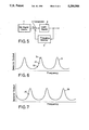
As the frequency detector 6, a Fabry-Perot interferometer or a gas absorption spectrometer is chiefly used. The curve 31 of FIG. 6 shows a detection profile of the Fabry-Perot interferometer and the curve 41 of FIG. 8 shows a detection profile of the gas spectrometer. In the former case, the point 33 on the profile of FIG. 6 is selected as a detection point and, in the latter case, the point 43 of FIG. 8 is selected as a detection point. However, the detection property of many frequency detectors 6 is obtained in a very restricted frequency range. For example, in the Fabry-Perot interference meter, only the range between the points 32 and 34 in FIG. 6 is available for a detector and in the gas spectrometer only the range between the points 42 and 44 in FIG. 8 is usable for a detector.
The frequency of the light source 5 in FIG. 5 can be varied by adjusting the light source 5 and the frequency detector 6. In the case of Fabry-Perot interference meter as the frequency detector 6, the detection property is adjusted to have a property as expressed by a curve 36 in FIG. 7 by controlling the conditions such as interference distance, refractive index, temperature and pressure, so that the point 33 in FIG. 6 is shifted to the point 37 in FIG. 7. In the case of gas spectrometer, the detection property is adjusted to have a detection property as expressed by the curve 46 in FIG. 9 so that the point 43 in FIG. 8 is shifted to the point 47 in FIG. 9.
PROBLEMS TO BE SOLVED BY THE INVENTION
In order to obtain a high stability in the frequency, a frequency detector 6 whose property is stable in, in other words, insensitive to, the use and environmental conditions is employed. Accordingly, in order to manipulate or adjust the frequency detector 6 an extensive variation in the use and environmental conditions must be introduced. Further, to obtain a frequency stability, the use and environmental conditions must be highly stabilized after the frequency has been changed. Thus, not only a great amount of energy is required to change the use and environmental conditions to a great extent but also a long period of time is required before it is stabilized.
OBJECTS OF THE INVENTION
A principal object of the invention is to provide a frequency stabilized light source, whose frequency can be changed quickly with a saved energy.
Another object of the invention is to provide a frequency stabilized light source, in which the stabilized frequency can be quickly changed with a saved energy in case the cycles of the detection profile of the frequency detector are slightly different from the intervals of the frequencies to be stabilized, by using together a small change in a reference signal source for the feedback circuit.
BRIEF SUMMARY OF THE INVENTION
To achieve these objects, according to the first aspect of the invention, a frequency stabilized light source which is stabilized at frequencies at uniform intervals comprises a light source 5 whose light frequency is varied with a signal from a reference signal source 4; a frequency detector 6 for detecting the frequency of the output of the light source 5, the cycles of the said frequency detector being the same as the uniform intervals; a comparator 2 for comparing the output of the frequency detector 6 and the output of the reference signal source 1; and a switch 3 having as its input the output of the comparator 2 for inputting the output to the light source 5, said switch being so operated that when the frequency of the light source 5 is to be changed the switch is opened and the output of the reference signal source 4 is changed to set the output frequency of the light source 5 near the desired frequency and then the switch 3 is closed.
According to the second aspect of the invention, in a frequency stabilized light source which is stabilized at frequencies of uniform intervals comprises a light source 5 whose light frequency is varied with a signal from a reference signal source 4; a frequency detector 6 for detecting the frequency of the output of the light source 5, the cycles of the said frequency detector being slightly different from the uniform intervals; a comparator 2 for comparing the output of the frequency detector 6 and the output of the reference signal source 1; and a switch 3 having as its input the output of the comparator 2 for inputting the output to the light source 5, said switch being so operated that when the frequency of the light source 5 is to be changed the switch is opened and the output signal of the reference signal source 4 is changed to set the output frequency of the light source 5 near the desired frequency and then the switch 3 is closed and the reference signal source 1 is finely adjusted.
BRIEF EXPLANATION OF THE DRAWINGS
FIG. 1 shows a construction of a frequency stabilized light source according to the present invention;
FIG. 2 shows an explanatory diagram of the function of the frequency stabilization according to the first embodiment of the present invention;
FIG. 3 shows an explanatory diagram of the function of the frequency stabilization according to the second embodiment of the present invention;
FIG. 4 illustrates a specific embodiment of the frequency stabilized light source according to the present invention; and
FIG. 5 shows a construction of a frequency stabilized light source according to the conventional technique; and
FIGS. 6, 7, 8 and 9 are explanatory diagrams for explaining the function of the light source of FIG. 5.
DESCRIPTION OF A PREFERRED EMBODIMENT OF THE INVENTION
Referring to FIG. 1, a frequency stabilized light source according to the first embodiment of the present invention is illustrated. In this figure, the various elements are the same as those illustrated in FIG. 2 except that a switch 3 and a reference signal source 4 are further employed. A feed back loop is formed by the reference signal source 1, the comparator 2, switch 3 and a frequency detector 6.
FIG. 2 shows a detection profile of Fabry-Perot interferometer used as the frequency detector 6 and the points 12, 13 and 14 are the frequencies which are to be stabilized.
In operation, it is assumed that when the switch 3 is opened, the light frequency of the light source 5 is at the point 15 in FIG. 2, and the reference signal source 1 is generating such a signal that the output of the comparator 2 is zero when the light source 5 is generating a light of a frequency at the point 12. When the switch 3 is closed the output frequency of the light source 5 is sensed by the frequency detector 6 and is compared with the reference frequency from the reference signal source 1. The frequency deviation from the point 12 is fed back to the light source 5 and the output frequency of the light source 5 is thus stabilized at the point 12.
Next, the case where the frequency is changed from the point 12 to the point 14 in FIG. 2. In the first embodiment, the response of the feedback circuit 7 remains the same in the vicinity of the points 12, 13 and 14 because the cycles of the detection profile of the frequency detector 6 are the same as the intervals of the frequencies to be stabilized. Accordingly, by opening the switch 3 and changing the output signal of the reference signal source 4 to set the output frequency of the light 5 at the point 16 and then closing the switch 3, the output frequency of the light source 5 is stabilized at the point 14 without manipulating the frequency detector 6, just as the case where the output of the light source 5 is changed from the point 12 to the point 15 as previously described.
Next, a principle of the second embodiment according to the present invention will be described in connection with FIG. 3. The frequency detection profile has frequency intervals which are slightly different from those of the frequencies to be stabilized. 21 of FIG. 3 is a detection profile obtained by using Fabry-Perot interferometer and the points 22, 23, and 24 in FIG. 3 indicate the frequencies to be stabilized.
Next, the case where the frequency is changed from the point 22 to the point 24. Since the cycles of the frequency detector are the same as the frequency intervals between the points 22, 25 and 26, the response of the feedback circuit 7 is the same in the vicinity of the points 22, 25 and 26. Accordingly, when the switch 3 is opened and the output signal of the reference signal source 4 is changed to set the output of the light source 5 at the point 27 and thereafter the switch 3 is closed, the output frequency of the light source 5 is stabilized to the point 26 without manipulating the frequency detector 6.
In this condition, when the reference signal source 1 is changed, the output frequency of the light source 5 is varied according to this change, it is possible to set the output frequency at the point 24 by checking beforehand the magnitude of the output of the reference signal where the output frequency is at the point 25 and controlling the reference signal source 1 to this magnitude, the output frequency of the light source 5 is set at 24.
A more specific embodiment of the first embodiment of the present invention is illustrated in FIG. 4 wherein 4A is a temperature control circuit, 4B is a reference electric source. 5A is an amplifier, 5B is a laser diode (LD), 6A is a Fabry-Perot interferometer used as a frequency detector, 6B and 6C are photodiodes (PDs) and 6D is a correction circuit. The other elements are the same as those illustrated in FIG. 1. The temperature control circuit 4A and the reference signal source 4B form together a reference signal source 4, the amplifier 5A and the LD 5B constitute a light source 5, the interferometer 6A, the PD 6B, the PD 6C and the correction circuit 6D form a frequency detector. The temperature control circuit 4A sets the temperature of the LD 5B and the reference signal source 4B sets a rough output frequency of the LD 5B.
A portion of the light from the LD 5B passes through the interferometer 6A where the variation of the frequency is converted into a variation of a level. The output of the LD 5B is converted into an electric signal and the output of the interferometer 6A into an electric signal by the PD 6B. Both outputs of the PD 6B and PD 6C are inputted to the correction circuit 6D. This correction circuit 6D is used for removing the level variation of the LD 5B from the output of the interferometer 6A and sends only the information on the frequency of the LD 5B to the comparator 2.
The comparator 2 compares the reference electric source 1 with the output of the correction circuit 6D to detect the deviation of the LD 5B from the stabilized frequency and upon closing the switch 3, the deviation is negatively fed back to the LD 5B through the amplifier 5A to stabilize the frequency.
For example, it is assumed that the frequencies to be stabilized are 200 THz, 200.01 THz and 200.03 THz, and the detection frequency of the interferometer 6A is 10 GHz. It is also assumed that the LD 5B is temperature controlled to 25° C. and the output frequency prior to the frequency-stabilization is 200.0001 THz. Under these conditions, when the switch 3 is closed from its open condition, the output frequency of the LD 5B becomes stabilized at 200 THz.
Then, when the switch 3 is opened from its closed condition, the output frequency of the LD 5B returns to 200.001 THz. If it is assumed that the LD 5B has a frequency sensitivity of -10 GHz/°C., the output frequency of the LD 5B becomes 200.0201 THz. When the switch 3 is closed from its open condition, the output frequency of the LD 5B becomes stabilized at 200.02 THz. As the LD 5B is small both in size and heat capacity, the temperature can be swiftly changed and as a result the frequency switching is also made quickly.
The second embodiment of the present invention is such a case where the detection frequency of the interferometer is 9.9 GHz. In this case, even if the LD 5B is adjusted to be stabilized to 200 THz, when the switch 3 is closed at a temperature of 23° C., the frequency becomes 200.0198 THz. Here, the reference signal source 1 is finely changed so that the output frequency becomes 200.02 YHz. This change must be obtained beforehand. Thus, even if the frequency of the detection frequency of the interferometer and the frequency to be stabilized are slightly different, a quick stabilization can be achieved without manipulating the frequency detector.
According to the present invention, by using the same cycles of the frequency detector as the intervals of the frequencies to be stabilized, the stabilized frequency can be quickly changed with saved energy. Further, when the cycles of the frequency detector are slightly different from the intervals of the frequencies to be stabilized, the stabilized frequency can be quickly changed with saved energy by using together a slight variation of the reference signal source of the feedback circuit.

Claims (2)

We claim:
1. A frequency stabilized light source which is stabilized by frequencies of uniform intervals comprises:
a light source 5 whose light frequency is varied with a signal from a reference signal source 4;
a frequency detector 6 for detecting the frequency of the output of the light source 5, cycles of the said frequency detector being the same as said uniform intervals;
a comparator 2 for comparing the output of the frequency detector 6 with the output of a reference signal source 1; and
a switch 3 having as its input the output of its comparator 2 for inputting the output to the light source 5, said switch being so operated that when the frequency of the light source 5 is to be changed the switch is opened and the output of the reference signal source 4 is changed to set the output frequency of the light source 5 near the desired frequency and then the switch 3 is closed.
2. A frequency stabilized light source which is stabilized by frequencies of uniform intervals comprises a light source 5 whose light frequency is varied with a signal from a reference signal source 4;
a frequency detector 6 for detecting the frequency of the output of the light source 5, cycles of the said frequency detector being slightly different from said uniform intervals;
a comparator 2 for comparing the output of the frequency detector 6 with the output of reference signal source 1; and
a switch 3 having as its input the output of the comparator 2 for inputting the output to the light source 5, said switch being so operated that when the frequency of the light source 5 is to be changed the switch is opened and the output signal of the reference signal source 4 is changed to set the output frequency of the light source 5 near the desired frequency and then the switch 3 is closed and the light source 5 is finely adjusted.
US07/878,945 1991-05-10 1992-05-05 Frequency stabilized light source Expired - Lifetime US5286966A (en)

Applications Claiming Priority (2)

Application Number Priority Date Filing Date Title
JP3133319A JPH04335588A (en) 1991-05-10 1991-05-10 Frequency-stabilized light source
JP3-133319 1991-05-10

Publications (1)

Publication Number Publication Date
US5286966A true US5286966A (en) 1994-02-15

Family

ID=15101918

Family Applications (1)

Application Number Title Priority Date Filing Date
US07/878,945 Expired - Lifetime US5286966A (en) 1991-05-10 1992-05-05 Frequency stabilized light source

Country Status (3)

Country Link
US (1) US5286966A (en)
JP (1) JPH04335588A (en)
DE (1) DE4215156A1 (en)

Cited By (1)

* Cited by examiner, † Cited by third party
Publication number Priority date Publication date Assignee Title
EP1156563A2 (en) * 2000-03-31 2001-11-21 Hitachi, Ltd. Laser wavelength stabilisation system for optical commmunication

Families Citing this family (3)

* Cited by examiner, † Cited by third party
Publication number Priority date Publication date Assignee Title
JP5447485B2 (en) * 2011-10-12 2014-03-19 富士通株式会社 Tunable laser
JP6308456B2 (en) * 2013-07-31 2018-04-11 住友電工デバイス・イノベーション株式会社 Control method of wavelength tunable laser
JP6319721B2 (en) * 2014-01-31 2018-05-09 住友電工デバイス・イノベーション株式会社 Control method of wavelength tunable laser

Citations (4)

* Cited by examiner, † Cited by third party
Publication number Priority date Publication date Assignee Title
US4583228A (en) * 1983-11-21 1986-04-15 At&T Bell Laboratories Frequency stabilization of lasers
US4947398A (en) * 1988-10-20 1990-08-07 Mitsubishi Denki Kabushiki Kaisha Laser device with wavelength stabilization control and method of operating the same
US5068864A (en) * 1990-05-04 1991-11-26 Laser Science, Inc. Laser frequency stabilization
US5119391A (en) * 1990-01-16 1992-06-02 Oki Electric Industry Co., Ltd. Automatic frequency control circuit for coherent diversity reception

Family Cites Families (1)

* Cited by examiner, † Cited by third party
Publication number Priority date Publication date Assignee Title
US4914666A (en) * 1989-05-04 1990-04-03 At&T Bell Laboratories Random-access digitally -tuned optical frequency synthesizer

Patent Citations (4)

* Cited by examiner, † Cited by third party
Publication number Priority date Publication date Assignee Title
US4583228A (en) * 1983-11-21 1986-04-15 At&T Bell Laboratories Frequency stabilization of lasers
US4947398A (en) * 1988-10-20 1990-08-07 Mitsubishi Denki Kabushiki Kaisha Laser device with wavelength stabilization control and method of operating the same
US5119391A (en) * 1990-01-16 1992-06-02 Oki Electric Industry Co., Ltd. Automatic frequency control circuit for coherent diversity reception
US5068864A (en) * 1990-05-04 1991-11-26 Laser Science, Inc. Laser frequency stabilization

Cited By (4)

* Cited by examiner, † Cited by third party
Publication number Priority date Publication date Assignee Title
EP1156563A2 (en) * 2000-03-31 2001-11-21 Hitachi, Ltd. Laser wavelength stabilisation system for optical commmunication
US20020051270A1 (en) * 2000-03-31 2002-05-02 Kimio Tatsuno Optical fiber communication equipment and its applied optical systems
EP1156563A3 (en) * 2000-03-31 2004-06-09 Hitachi, Ltd. Laser wavelength stabilisation system for optical commmunication
US7164865B2 (en) 2000-03-31 2007-01-16 Opnext Japan, Inc. Optical fiber communication equipment and its applied optical systems

Also Published As

Publication number Publication date
DE4215156A1 (en) 1992-11-12
JPH04335588A (en) 1992-11-24

Similar Documents

Publication Publication Date Title
US5777773A (en) Optical frequency control system and method
US5748325A (en) Gas detector for plural target zones
US5637872A (en) Gas detector
US8064740B2 (en) Arrangement for the electro-optical control and fast modulation of THz transmitters and THz measuring systems
US4433238A (en) Optical measurement system for spectral analysis
CN107437722B (en) Modulation-free frequency stabilization method and device for semiconductor laser
Kawanishi et al. Wideband frequency-response measurement of optical receivers using optical heterodyne detection
US6898221B2 (en) Apparatus for frequency tuning and locking and method for operating same
US5031234A (en) Fiber optic frequency transfer link
US5286966A (en) Frequency stabilized light source
US5432629A (en) Light transmission device capable of stably transmitting a modulated output light beam
US7023534B2 (en) Optical modulating apparatus having bias controller and bias control method
KR0160925B1 (en) Bit frequency stabilization apparatus of pulse light and probe light for detecting the distribution of optical fiber strain
US9825422B2 (en) Optic-microwave frequency discriminator for laser frequency difference locking, and method thereof
JP2006502391A (en) Method and apparatus for monitoring an interferometer
EP1372275B1 (en) Controlling an optical source using a beat frequency
JPS6148101B2 (en)
US5349458A (en) Method for detecting external influence on an optical cable
CA2102270A1 (en) Wavelength Switching Light Source
US4979825A (en) Device for measuring optical frequency modulation characteristics
Ohtsu et al. A simple interferometric method for monitoring mode hopping in tunable external-cavity semiconductor lasers
US5986255A (en) Photoelectric cell with lockable differential processing
US7016382B2 (en) Method and apparatus for stabilizing laser wavelength
US10476230B2 (en) Etalon-based wavelength locking apparatus and alignment method
KR102620196B1 (en) Laser Oscillation Apparatus Capable of Stabilizing Frequency Characteristics of Laser to Be Oscillated

Legal Events

Date Code Title Description
AS Assignment

Owner name: NIPPON TELEGRAPH AND TELEPHONE CORPORATION, JAPAN

Free format text: ASSIGNMENT OF ASSIGNORS INTEREST.;ASSIGNORS:MATSUURA, SATOSHI;RI, TEKKEN;HORIGUCHI, TSUNEO;AND OTHERS;REEL/FRAME:006212/0615

Effective date: 19920430

Owner name: ANDO ELECTRIC CO., LTD., JAPAN

Free format text: ASSIGNMENT OF ASSIGNORS INTEREST.;ASSIGNORS:MATSUURA, SATOSHI;RI, TEKKEN;HORIGUCHI, TSUNEO;AND OTHERS;REEL/FRAME:006212/0615

Effective date: 19920430

FEPP Fee payment procedure

Free format text: PAYOR NUMBER ASSIGNED (ORIGINAL EVENT CODE: ASPN); ENTITY STATUS OF PATENT OWNER: LARGE ENTITY

STCF Information on status: patent grant

Free format text: PATENTED CASE

CC Certificate of correction
FPAY Fee payment

Year of fee payment: 4

FPAY Fee payment

Year of fee payment: 8

FPAY Fee payment

Year of fee payment: 12