US5293163A - Navigation apparatus for vehicles - Google Patents
Navigation apparatus for vehicles Download PDFInfo
- Publication number
- US5293163A US5293163A US08/108,834 US10883493A US5293163A US 5293163 A US5293163 A US 5293163A US 10883493 A US10883493 A US 10883493A US 5293163 A US5293163 A US 5293163A
- Authority
- US
- United States
- Prior art keywords
- information
- vehicle
- displayed
- road map
- map information
- Prior art date
- Legal status (The legal status is an assumption and is not a legal conclusion. Google has not performed a legal analysis and makes no representation as to the accuracy of the status listed.)
- Expired - Lifetime
Links
Images


Classifications
-
- G—PHYSICS
- G01—MEASURING; TESTING
- G01C—MEASURING DISTANCES, LEVELS OR BEARINGS; SURVEYING; NAVIGATION; GYROSCOPIC INSTRUMENTS; PHOTOGRAMMETRY OR VIDEOGRAMMETRY
- G01C21/00—Navigation; Navigational instruments not provided for in groups G01C1/00 - G01C19/00
- G01C21/26—Navigation; Navigational instruments not provided for in groups G01C1/00 - G01C19/00 specially adapted for navigation in a road network
- G01C21/34—Route searching; Route guidance
- G01C21/36—Input/output arrangements for on-board computers
- G01C21/3626—Details of the output of route guidance instructions
- G01C21/3655—Timing of guidance instructions
-
- G—PHYSICS
- G01—MEASURING; TESTING
- G01C—MEASURING DISTANCES, LEVELS OR BEARINGS; SURVEYING; NAVIGATION; GYROSCOPIC INSTRUMENTS; PHOTOGRAMMETRY OR VIDEOGRAMMETRY
- G01C21/00—Navigation; Navigational instruments not provided for in groups G01C1/00 - G01C19/00
- G01C21/26—Navigation; Navigational instruments not provided for in groups G01C1/00 - G01C19/00 specially adapted for navigation in a road network
- G01C21/34—Route searching; Route guidance
- G01C21/36—Input/output arrangements for on-board computers
- G01C21/3667—Display of a road map
-
- G—PHYSICS
- G01—MEASURING; TESTING
- G01C—MEASURING DISTANCES, LEVELS OR BEARINGS; SURVEYING; NAVIGATION; GYROSCOPIC INSTRUMENTS; PHOTOGRAMMETRY OR VIDEOGRAMMETRY
- G01C21/00—Navigation; Navigational instruments not provided for in groups G01C1/00 - G01C19/00
- G01C21/26—Navigation; Navigational instruments not provided for in groups G01C1/00 - G01C19/00 specially adapted for navigation in a road network
- G01C21/34—Route searching; Route guidance
- G01C21/36—Input/output arrangements for on-board computers
- G01C21/3679—Retrieval, searching and output of POI information, e.g. hotels, restaurants, shops, filling stations, parking facilities
- G01C21/3682—Retrieval, searching and output of POI information, e.g. hotels, restaurants, shops, filling stations, parking facilities output of POI information on a road map
-
- G—PHYSICS
- G01—MEASURING; TESTING
- G01C—MEASURING DISTANCES, LEVELS OR BEARINGS; SURVEYING; NAVIGATION; GYROSCOPIC INSTRUMENTS; PHOTOGRAMMETRY OR VIDEOGRAMMETRY
- G01C21/00—Navigation; Navigational instruments not provided for in groups G01C1/00 - G01C19/00
- G01C21/26—Navigation; Navigational instruments not provided for in groups G01C1/00 - G01C19/00 specially adapted for navigation in a road network
- G01C21/34—Route searching; Route guidance
- G01C21/36—Input/output arrangements for on-board computers
- G01C21/3679—Retrieval, searching and output of POI information, e.g. hotels, restaurants, shops, filling stations, parking facilities
- G01C21/3685—Retrieval, searching and output of POI information, e.g. hotels, restaurants, shops, filling stations, parking facilities the POI's being parking facilities
-
- G—PHYSICS
- G08—SIGNALLING
- G08G—TRAFFIC CONTROL SYSTEMS
- G08G1/00—Traffic control systems for road vehicles
- G08G1/09—Arrangements for giving variable traffic instructions
- G08G1/0962—Arrangements for giving variable traffic instructions having an indicator mounted inside the vehicle, e.g. giving voice messages
- G08G1/0968—Systems involving transmission of navigation instructions to the vehicle
- G08G1/0969—Systems involving transmission of navigation instructions to the vehicle having a display in the form of a map
Definitions
- the present invention relates to the improvement of a navigation apparatus for vehicles, which has the function of displaying the current position, travelling direction, etc of the vehicle with a map image overlapped on the screen of such a display device as CRT display.
- the present invention provides a navigation system having display means for displaying road information, which comprises:
- reading means for searching for the road information related to the estimated current position of the vehicle and for reading out that information from the storage means;
- display restriction means for restricting display of the road information which is determined less related to the travel of the vehicle by the determination means.
- the logical data may be the identification of a road or a building, the location of a road, the connection of roads, the direction of a road, the data as to whether the road is a one-way road or not, or the location of a parking lot, for example.
- Another object of the present invention is to provide a navigation system which has the function of inputting auxiliary information from the driver or an external source in order to achieve more accurate determination as to how closely the road information is related to the travel of the vehicle.
- the auxiliary information comprises a range of the direction in which the vehicle may travel.
- the auxiliary information comprises current traffic information on roads located near the current position.
- the auxiliary information comprises externally obtained current traffic information on the road near the current position and selection criterion information for selection of the traffic information.
- the traffic information comprises data as to how much the roads on which the vehicle may travel is jammed with cars.
- the traffic information comprises the occupation rates of the parking lots.
- FIG. 1 is a block diagram of an embodiment of a navigation system according to the present invention
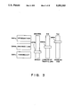
- FIG. 2 shows the relation between each of stations from which map information (traffic information) is sent out and the vehicle
- FIG. 3 shows the switches incorporated in the navigation system of FIG. 1 to input various types of auxiliary data
- FIG. 4A explains the structure of information stored in a CDROM
- FIG. 4B shows a format of map data stored in the CDROM
- FIGS. 5A and 5B explain the display conducted in the mode 1 which is one of the control methods in the embodiment according to the present invention
- FIG. 6 explains the relative positions of the places displayed in FIGS. 5A and 5B;
- FIG. 7A explains the display conducted when there is no display control of the mode 2;
- FIG. 7B explains the display conducted when there is display control of the mode 3;
- FIG. 7C explains the display conducted when there is display control of the mode 2;
- FIG. 8 explains the display conducted when there is display control of the mode 4.
- FIG. 9 explains the display conducted when there is display control of the mode 5;
- FIGS. 10A and 10B explain the display conducted when there is display control of the mode 6;
- FIG. 11 explains the display conducted when there is display control of the mode 7;
- FIGS. 12A to 12F explain the formats of various types of internal and external information used in the controls of the mode 1 to mode 7;
- FIG. 13 shows the table used to determine the mode
- FIG. 14 is a flowchart of the control procedures for the display conducted by the navigation system when one of mode 1 to mode 7 not designated;
- FIG. 15A is a flowchart of the control procedures for the mode 1;
- FIG. 15B is a flowchart of the control procedure when the vehicle is within 300 meters of an intersection
- FIG. 16 is a flowchart of the control procedures for the mode 2;
- FIG. 17 is a flowchart of the control procedures for the mode 3.
- FIG. 18 is a flowchart of the control procedures for the mode 4.
- FIG. 19 is a flowchart of the control procedures for the mode 5;
- FIG. 20 is a flowchart of the control procedures for the mode 6;
- FIG. 21 is a flowchart of the control procedures for the mode 7.
- FIG. 22 explains the arrangement of the storage areas in an image memory 10 for storing image data in the navigation system.
- FIG. 1 is a block diagram of the embodiment of a navigation system according to the present invention.
- this navigation system among a large amount of information to be displayed, the data required for navigation is selectively displayed on a CRT 26. Therefore, determination of the viewpoint from which the information to be displayed is selected is essential.
- examples of information displayed on the CRT include the courses, names, and directions of a road, the names of the places along roads; the locations and names of intersections; the locations and names of buildings; the locations of parking lots; the data as to whether the roads are one-way roads or not; and the traffic jam information.
- These information are related to the travel of a vehicle on a road and are thus called broadly "road information”.
- "Road information” is classified into “internal map information" stored in a vehicle, and “external map information” input from an external source.
- the internal map information is the road information stored in a storage medium (which may be a CD-ROM 25a) mounted on the vehicle. As the ROM 25a is read-out only, this type of road information is not changed.
- the external map information is input from a traffic information receiver 24.
- the external map information may be the traffic jam data of a road or the occupation rate of a parking lot.
- the external map information is changing every moment and hence must depend upon an external information source.
- This system includes a controller 1, a CRT 26 for displaying images for navigation or TV broadcast, a touch panel 23 which allows the CRT 26 to be used as a user interface and which consists of light-emitting diodes 27 and 29 and light-receiving elements 28 and 30, a television tuner 22, a CD deck 25 which is a CD player, a ROM 25a which is the recording medium, a group of various types of operation switches SW, a global positioning system (GPS) 19 which is the means for estimating the position of the vehicle, a direction sensor 20 for measuring the direction of travel of the vehicle, a distance sensor 21 for detecting the travelling distance, and the aforementioned traffic information receiver 24 for inputting the "external map information”.
- GPS global positioning system
- the touch panel 23 is used when the driver designates a destination while viewing the display screen or inputs a desired travelling route.
- the group of switches SW1 to SW8 which is connected to CPU 7 through I/O 2 will be described in detail. Whether the CRT 26 is used as the television display device or as the navigation display device is determined by the driver's pressing the switch SW8 or SW1.
- the traffic information can be obtained by receiving radio waves sent from a plurality of stations, as shown in FIG. 2.
- the position of the vehicle can be estimated by integrating the travelling distance detected by the distance sensor 21 at predetermined time intervals with the travelling direction detected by the senor 20 which detects the terrestrial magnetism taken into consideration.
- the detection is made via I/O 3 through an interrupt handling mechanism IRT 7a. Since the detection of the terrestrial magnetism generates errors, the thus-obtained position of the vehicle is adequately corrected using the position of the vehicle detected by the GPS device 19.
- the controller 1 automatically performs selection of the information to be displayed.
- the display selection switch SW4 will be described with reference to FIG. 3.
- the switch SW4 (FIG. 3) consists of normal switches SW4a to SW4c and three slide switches SW4d to SW4f.
- the intersection switch 4a When the intersection switch 4a is pressed, the location of an intersection can be input from the touch panel 23.
- the switch SW4b is pressed, display of the road together with the data representing whether or not the road is a one-way road or together with the data representing whether or not the road is congested with cars is instructed to the system.
- the parking-lot-information switch 4c When the parking-lot-information switch 4c is pressed, the parking lot is displayed conspicuously.
- the three slide switches SW4d to SW4f will be detailed later.
- the reduction rate switch SW7 is used for selection of the reduction scale of the map. When it is desired that the map be displayed in detail, a small reduction scale is designated.
- FIG. 4A shows how the CD-ROM 25a is divided into storage areas.
- the map information (internal map information) to be displayed on one screen on the minimum reduction scale is stored in blocks.
- the map information consists of "outline data", "name-data” and "graphic data”.
- Outline data comprises the vector data representative of the outline of a road, river or building site.
- Single road is made up of a plurality of linked vectors.
- display of the outline data is not restricted, i.e., they are always displayed, in this embodiment.
- Name-data comprises the character data representing the name of a road, building or intersection.
- the individual name-data further contains the position where that name is to be displayed.
- name itself is not visible to the driver who looks out from the window of the vehicle, and is hence an object of the restriction of display in this embodiment.
- Graphic data comprises the figure which symbolizes a road, river or building.
- a one-way road may be symbolized by the figure indicated by “D” in FIG. 7A.
- a traffic jam may be symbolized by “C” in FIG. 7A.
- the current position of the vehicle may be symbolized by “A” in FIG. 7A. Since “symbol” itself is not visible, the display of it can be restricted in this embodiment.
- FIG. 4B shows how a road is expressed using the aforementioned "outline data", "name-data” and "graphic data”.
- the first field is used for the type of data. In this case, "1" indicating that the data is the road data is stored.
- a subsequent field is used for the identification No. ID for identifying that road.
- the field following the ID field is used for a pointer indicating the position where "name-data" (FIG. 4A) representing the name of that road is stored.
- the following field is used for the type of road (whether or not the road is a one-way road).
- a subsequent field is used for storing a pointer which specifies the symbol representative of that road (when necessary).
- the last field is used for storing the linkage of the outline data for a subsequent screen which follows the outline data displayed on this screen.
- map information stored in the CD-ROM 25a contains the information shown in FIGS. 12A and 12B.
- This embodiment is constructed so that necessary information is selectively displayed from a large amount of displayable information, and the standard for selection can be set or changed by the driver himself.
- the information on the standard for selection is used to assist the system to make the selection and is therefore called "auxiliary information".
- the information which is the object for selection is "name-data" and "graphic data”.
- the standard for selection conducted in this system is classified as follows:
- FIG. 5A shows a case in which all the passing points stored in the CD-ROM 25a, located along "National Route 1" and “Sotobori dori” ("Sotobori” Street) starting from the “Toranomon” intersection, are displayed when the vehicle reaches 300 m before the "Toranomon” intersection where "National Route 1" crosses “Sotobori dori”.
- FIG. 6 shows the relative positions of these places. According to FIG. 6, “Tameike” (0.5 km), “Shinbashi” (1 km) and “Akabane” (2 km) are considered to be at short distances from "Toranomon”.
- FIG. 7A shows the display screen with no restrictions on the display.
- an arrow indicated by “A” represents the current position of the vehicle.
- “E” represents the road designated through the touch panel 23 when the switch SW5 is activated.
- Roads identified by “D” are one-way roads.
- Roads identified with “C” consisting of a with cars. The number of arrows indicates the length of the traffic jam.
- the traffic jam information is one type of "external map information", as stated above.
- FIG. 7C shows a case where the information on the roads located near the road selected by the system is displayed.
- an intersection G is designated through the touch panel 23 in a state where the switch SW4 is pressed. In this case, only the information on the roads near the intersection G is displayed because the system determines that the information on the roads which are not located near the location designated by the driver is not important.
- b-1-1 When the direction toward the destination has been inferred (proposed) by the system.
- the system can calculate the direction toward the destination from the direction in which the vehicle is travelling.
- the present direction of travel may differ from that toward the destination.
- a fan-shaped area F which fans out in the directions of the travel by a predetermined angle (which is variable) is set using the slide switch 4d, as shown in FIG. 9, and display of the road information on the roads located within this area is given preference. This is because the possibility that the vehicle will travel along the roads located within the area F is high and display of those roads is thus important.
- the system may be able to calculate the destination. For example, when the switch 4c is pressed, the system can determine that the driver may be heading for a nearby parking lot. In other words, the destination is either of the parking lots having a parking space in the neighborhood. In other words, the necessity that the road information on the parking lots which are full is low. Furthermore, as a plurality of parking lots may exit, the driver teaches the standard for selection to the system. In this embodiment, the standard for selection is the parking fee designated by the slide switch 4f. If the driver desires a parking lot whose parking fee is relatively high, he or she sets the slide switch 4f in the manner shown in FIG. 10A, and a lot of parking lots having a parking space may be displayed.
- the driver desires a parking lot whose parking fee is relatively cheap, he or she sets the slide switch 4f in the manner shown in FIG. 10B. In this way, the number of parking lots to be displayed is reduced, and only parking lots which are desired by the driver are selectively displayed, as shown in FIG. 10B.
- the information on the parking fee of each parking lot may be stored in the CD-ROM25a or it may be received through the receiver 24 from a nearby station as the traffic information.
- Occurrence and/or length of a traffic jam, shown in FIG. 7A, and as to whether or not a parking lot has a parking space, shown in FIG. 10, are examples of the external information.
- the system inputs the external map information through the receiver 24 and determines the importance thereof utilizing the direction of travel, route or parking fee as "auxiliary data".
- the system does not display the road information which is determined as less important.
- FIG. 11 shows another example of utilization of the external map information.
- FIG. 4B shows how the information on the single road is stored in the ROM 25a.
- FIGS. 12A and 12B show the formats of various types of "internal map information" other than the road information, stored in the CD-ROM 25a.
- FIGS. 12C and 12D show the formats of various types of "external map information" obtained through the traffic information receiver 24 from the external source.
- the system periodically receives the various types of "external map information" and stores them in a RAM 8 in a predetermined format.
- FIGS. 12C and 12D show such "external map information”.
- FIGS. 12E and 12F show various types of information designated by the driver.
- the "destination" data shown in FIG. 12E is made up of the destination of the driver and the locations along the route which leads to the destination. The destination and locations along the route are input from the touch panel 23 when the switch SW5 is pressed, as stated above. In a case where the driver inputs the destination and locations along the route, the last location which the driver inputs is regarded as the destination of the driver. If the switch SW6 is pressed after the destination has been input from the touch panel, the route data indicates the shortest route to the designation that the system determines. In FIG. 12E, a flag indicates whether the route data is estimated (proposed) by the system or designated by the driver. The information shown in FIG. 12E is utilized for display control related to FIG. 7C.
- FIG. 12F shows "intersection" data designated by the driver and utilized for display control shown in FIG. 8.
- FIG. 13 shows various types of operation modes for display control which are selected on the basis of the operation patterns of various switches shown in FIGS. 1 and 3. In this system, there are seven types of modes (modes 1-7) in relation to the display control shown in FIGS. 5 to 11.
- FIG. 14 shows the control procedures for the display control (normal display control) required when none of the seven modes is selected.
- the map information stored in the CD-ROM 25a and those obtained from the external sources are all displayed.
- Display for the navigation in this embodiment is characterized in that the top of the CRT screen always indicates the north, and that the map image (images except for the vehicle) is scrolled while the position of the vehicle is located at the center of the CRT screen.
- the direction in which the vehicle is travelling is indicated by the direction of the arrow which symbolizes the vehicle.
- nine map screens are entered with the present vehicle position as the center.
- step S2 the value of the reduction scale, set by the switch SW7, is read in.
- step S4 the current position is estimated by means of the GPS device 19, the distance sensor 21 and the direction sensor 20.
- step S6 it is determined whether or not new screens must be read in the image memory 10 from the CD-ROM 25a when the display symbol of the vehicle "A" moves from the previously estimated vehicle position to the presently estimated vehicle position (when the screen is scrolled). The answer becomes YES when the vehicle position reaches the position indicated by the broken line in FIG. 22. If the answer is NO, the control goes to step S14 and the screen is scrolled such that the vehicle position is kept at the center of the screen, and the direction of the arrow "A" which symbolizes the vehicle is then updated in step S16.
- step S6 If it is determined in step S6 that the new screen must be read in from the CD-ROM 25a, the control goes to step S8 and the new screen data is read in from the ROM 25a. Thereafter, in step S10, the newly read “outline data" (vector data) is converted into the dot data representing the road or the like and is written in the image memory 10. Next, in step S12, the newly read name-data and graphic data are converted into the dot image and are written in the image memory 10. Subsequently, the background image is scrolled and the vehicle position is updated in steps S14 and 16.
- step S10 the newly read “outline data” (vector data) is converted into the dot data representing the road or the like and is written in the image memory 10.
- step S12 the newly read name-data and graphic data are converted into the dot image and are written in the image memory 10. Subsequently, the background image is scrolled and the vehicle position is updated in steps S14 and 16.
- FIG. 15A shows the procedures for the screen display control in the mode 1.
- this control of the mode 1 all the internal map information and external map information that can be displayed are displayed on the screen while the vehicle is far from the intersection, whereas display shown in FIG. 5B is conducted while the vehicle is within 300 m from the intersection.
- step S20 the value of the reduction scale for the map set by the switch SW7 is read in.
- step S22 the current position is estimated using the GPS device 19, the distance sensor 21 and the direction sensor 20.
- step S24 it is determined whether or not new screens must be read into the image memory 10 from the CD-ROM 25a when the display symbol of the vehicle "A" moves from the previously estimated vehicle position to the presently estimated vehicle position (when the screen is scrolled).
- step S30 the screen is scrolled so that the vehicle position is kept at the center of the screen, and the direction of the arrow "A" which symbolizes the vehicle is then updated in step S32.
- step S24 the process goes to step S26 and the new screen data is read in from the ROM 25a.
- step S28 the newly read "outline data" (vector data) is converted into the dot image representing the road or the like and is written in the image memory 10.
- step S34 the external map information is input from the receiver 24.
- step S36 the information in the previously received external map information which has become unnecessary as a consequence of the travel of the vehicle is erased from the RAM 8.
- the newest outline data representing the roads, bridges and/or buildings are written in the image memory 10, and the CRT 26 is set such that the newest vehicle position is displayed at the center of the screen. Also, the newest external map information is obtained.
- step S38 it is determined in step S38 whether or not the vehicle is within 300 m from a certain intersection. If the vehicle is not within 300 m, the name-data, graphic data (FIG. 4A) and the external map information are written in the image memory 10 in step S40 to display all the internal and external map information that can be displayed.
- step S42 the area corresponding to one screen with the vehicle position as the center is set in the CRT 26 as the area to be displayed, i.e., that area is displayed on the CRT 26. Thus, all the internal and external map information that can be displayed are displayed on the CRT 26 while the vehicle is far from the intersection.
- step S38 If it is determined in step S38 that the present vehicle position is near the intersection, an area corresponding to the display screen shown in FIG. 5B is written in the image memory 10 in step S44. Thereafter, in step S46, the intersection information shown in FIG. 12F is read in. In step S48, the remaining distance "L" from the current position to the destination is calculated. In step S50, the information on the approaching intersection is searched for from among the read intersection information. In step S52, the remaining distance "L" and a predetermined constant are compared with each other. If 0 km ⁇ L ⁇ 3 km, it is determined that the vehicle is near the destination. If 3 km ⁇ L ⁇ 10 km, it is determined that the vehicle is far from the destination. If L ⁇ 10 km, it is determined that the destination is very far.
- step S50 the intersection information searched for in step S50 is selectively displayed. That is, if 0 km ⁇ L ⁇ 3 km, only near locations by less than 3 km are displayed (in step S54). If 3 km ⁇ L ⁇ 10 km, only the locations separated by a distance from 3 km to less than 10 km are displayed (in step S56). If L ⁇ 10 km, only the locations separated by 10 km or more are displayed (in step S58). Thereafter, in step 60, the area set in step S44 is displayed on the CRT 26. In this mode 1, as only the locations corresponding to the distance to the destination are displayed on the CRT screen, the really necessary information alone is displayed, and visibility is thus improved.
- step S70 in FIG. 16 The control procedures preceding step S70 in FIG. 16 are the same as those from steps S28 to S36 in FIG. 15.
- steps S28 to S36 the newest outlines representing roads, bridges or buildings are written in the image memory 10, and the CRT 26 is set such that the newest vehicle position can be displayed at the center of the screen. Also, the newest external map information is obtained.
- step S70 in FIG. 16 the first route data shown in FIG. 12E is read in.
- step S72 roads located adjacent to this first route (namely, located in the vicinity of or crosses the first route) are searched for from the road information shown in FIG. 4B.
- step S74 from the searched internal map information on the searched adjoining roads (e.g., the information on one-way traffic or as to whether or not the road is closed for traffic, or the parking lot information) and external map information (e.g., whether or not the road is congested or whether the parking lot has a parking space or full), that on the adjacent roads located within a predetermined distance is searched for, and the searched data is written in the image memory 10 on top of the outline data in step S76. Processing from steps S70 to S76 are conducted on all the places shown in FIG. 12E. Finally, in step S80, the data is displayed on the CRT 26.
- the searched internal map information on the searched adjoining roads e.g., the information on one-way traffic or as to whether or not the road is closed for traffic, or the parking lot information
- external map information e.g., whether or not the road is congested or whether the parking lot has a parking space or full
- the mode 3 control will be described in connection to FIG. 7B. In the mode 3, only the road information on the designated roads along which the driver is going to pass is displayed.
- step S84 in FIG. 17 the first route data shown in FIG. 12E is read in.
- step S86 the roads en route are searched for from the road information shown in FIG. 4B.
- step S87 the internal and external map information on the searched road is searched for, and in step S88, the searched data is then written in the image memory 10 together with the outline data. Processing from steps S84 to S88 is conducted on all the routes within the data shown in FIG. 12E. Finally, in step S92, the obtained data is displayed on the CRT 26.
- step S100 the road information on roads located adjacent to intersections designated by the driver is displayed.
- step S102 roads which pass this read intersection are searched for from among the information shown in FIG. 12A.
- step S104 in the internal and external map information on the searched roads, map information on roads located within the predetermined distance is searched for, and in step S106, the searched data is written in the image memory 10 over the outline data.
- Process from steps S100 to S106 is conducted on all the intersections shown in FIG. 12F. Thereafter, the obtained data is displayed on the CRT 26 in step S110.
- step S140 the value set by the switch 4f is read in step S140.
- step S142 parking lots having a parking space are searched for from among the information shown in FIG. 12B using the parking lot information shown in FIG. 12D.
- step S144 parking lots whose parking fees are cheaper than that input by means of the switch 4f are searched for from among the parking lots searched in step S142.
- step S148 the searched data is converted into characters or symbols and written in the image memory 10.
- step S150 the contents of the image memory 10 are displayed.
- step S160 in FIG. 21 the value set by the switch 4e is read in.
- step 162 the locations of the traffic jams having a length longer than that set by the switch 4e are searched for from among the traffic jam information shown in FIG. 12C.
- step S164 the symbol corresponding to the length of the jam is set to each of the traffic jams.
- step S166 these symbols are written in the image memory 10.
- step S168 the contents of the image memory are displayed.
Abstract
A navigation apparatus for vehicles according to the present invention has a display device for displaying road information. The navigation system is designed to selectively display the road information which is close to the current position of the vehicle and/or the demands of the driver from a large amount of road information (each of which consists of image data to be displayed and logical data on which logical determination can be made).
Description
This is a continuation of application Ser. No. 07/711,614 filed on Jun. 5, 1991, now abandoned.
The present invention relates to the improvement of a navigation apparatus for vehicles, which has the function of displaying the current position, travelling direction, etc of the vehicle with a map image overlapped on the screen of such a display device as CRT display.
Such navigation apparatuses are generally designed to display on a CRT screen map information stored in a large-capacity storage device, such as a CD-ROM. Examples of the types of the map information include the courses, names, lengths, and directions of roads, the names of the places along a road, the locations and names of intersections, and the locations or names of buildings. These map information are incorporated in the vehicle and hence can be called "internal road information".
Navigation systems having means for receiving traffic information through the radio are also known. In this navigation system, all the traffic information that can be displayed presently is displayed on a CRT screen in accordance with the data received by the reception means (this data being hereinafter referred to as "external road information") and the internal road information. Such a navigation system is disclosed in, for example, Japanese Kokai No. 63-231477.
When all the internal road information, or all the internal and external road information, related to the travel of the vehicle is displayed on the screen of a display portion, as in the case of the aforementioned conventional examples, the amount of information displayed on the screen becomes too much and the visibility of the necessary information is deteriorated, although abundant information can be offered to the driver. For example, the traffic information about the roads in the opposite direction to that in which the vehicle is currently travelling is basically unnecessary for the driver.
Accordingly, an object of the present invention is to provide a navigation system which allows the road information required for driving to be displayed on the screen and hence notified adequately to the driver without reducing the visibility of the information displayed on the screen of a displaying device.
To achieve this object, the present invention provides a navigation system having display means for displaying road information, which comprises:
current position estimation means for estimating the current position of the vehicle;
storage means for storing a large amount of road information which consists of image data to be displayed and logical data on which logical determination can be made by determination means;
reading means for searching for the road information related to the estimated current position of the vehicle and for reading out that information from the storage means;
determination means for determining relation degree of the read out road information to the travel of the vehicle on the basis of the individual logical data contained in the read out road information; and
display restriction means for restricting display of the road information which is determined less related to the travel of the vehicle by the determination means.
In the aforementioned navigation system, the logical data may be the identification of a road or a building, the location of a road, the connection of roads, the direction of a road, the data as to whether the road is a one-way road or not, or the location of a parking lot, for example.
Another object of the present invention is to provide a navigation system which has the function of inputting auxiliary information from the driver or an external source in order to achieve more accurate determination as to how closely the road information is related to the travel of the vehicle.
In one preferred aspect of the present invention, the auxiliary information comprises a destination designated by the driver.
In another preferred aspect of the present invention, the auxiliary information comprises a range of the direction in which the vehicle may travel.
In another preferred aspect of the present invention, the auxiliary information comprises current traffic information on roads located near the current position.
In another preferred aspect of the present invention, the auxiliary information comprises externally obtained current traffic information on the road near the current position and selection criterion information for selection of the traffic information.
In another preferred aspect of the present invention, the traffic information comprises data as to how much the roads on which the vehicle may travel is jammed with cars.
In another preferred aspect of the present invention, the traffic information comprises the occupation rates of the parking lots.
Other objects and advantages besides those discussed above shall be apparent to those skilled in the art form the description of a preferred embodiment of the invention which follows. In the description, reference is made to accompanying drawings, which form a part hereof, and which illustrate an example of the invention. Such example, however, is not exhaustive of the various embodiments of the invention, and therefore reference is made to the claims which follow the description for determining the scope of the invention.
FIG. 1 is a block diagram of an embodiment of a navigation system according to the present invention;
FIG. 2 shows the relation between each of stations from which map information (traffic information) is sent out and the vehicle
FIG. 3 shows the switches incorporated in the navigation system of FIG. 1 to input various types of auxiliary data;
FIG. 4A explains the structure of information stored in a CDROM;
FIG. 4B shows a format of map data stored in the CDROM;
FIGS. 5A and 5B explain the display conducted in the mode 1 which is one of the control methods in the embodiment according to the present invention;
FIG. 6 explains the relative positions of the places displayed in FIGS. 5A and 5B;
FIG. 7A explains the display conducted when there is no display control of the mode 2;
FIG. 7B explains the display conducted when there is display control of the mode 3;
FIG. 7C explains the display conducted when there is display control of the mode 2;
FIG. 8 explains the display conducted when there is display control of the mode 4;
FIG. 9 explains the display conducted when there is display control of the mode 5;
FIGS. 10A and 10B explain the display conducted when there is display control of the mode 6;
FIG. 11 explains the display conducted when there is display control of the mode 7;
FIGS. 12A to 12F explain the formats of various types of internal and external information used in the controls of the mode 1 to mode 7;
FIG. 13 shows the table used to determine the mode;
FIG. 14 is a flowchart of the control procedures for the display conducted by the navigation system when one of mode 1 to mode 7 not designated;
FIG. 15A is a flowchart of the control procedures for the mode 1;
FIG. 15B is a flowchart of the control procedure when the vehicle is within 300 meters of an intersection;
FIG. 16 is a flowchart of the control procedures for the mode 2;
FIG. 17 is a flowchart of the control procedures for the mode 3;
FIG. 18 is a flowchart of the control procedures for the mode 4;
FIG. 19 is a flowchart of the control procedures for the mode 5;
FIG. 20 is a flowchart of the control procedures for the mode 6;
FIG. 21 is a flowchart of the control procedures for the mode 7; and
FIG. 22 explains the arrangement of the storage areas in an image memory 10 for storing image data in the navigation system.
An embodiment of the present invention will be described below with reference to the accompanying drawings.
FIG. 1 is a block diagram of the embodiment of a navigation system according to the present invention. In this navigation system, among a large amount of information to be displayed, the data required for navigation is selectively displayed on a CRT 26. Therefore, determination of the viewpoint from which the information to be displayed is selected is essential.
In this embodiment, examples of information displayed on the CRT include the courses, names, and directions of a road, the names of the places along roads; the locations and names of intersections; the locations and names of buildings; the locations of parking lots; the data as to whether the roads are one-way roads or not; and the traffic jam information. These information are related to the travel of a vehicle on a road and are thus called broadly "road information". "Road information" is classified into "internal map information" stored in a vehicle, and "external map information" input from an external source. The internal map information is the road information stored in a storage medium (which may be a CD-ROM 25a) mounted on the vehicle. As the ROM 25a is read-out only, this type of road information is not changed. The external map information is input from a traffic information receiver 24. The external map information may be the traffic jam data of a road or the occupation rate of a parking lot. The external map information is changing every moment and hence must depend upon an external information source.
The configuration of the navigation system shown in FIG. 1 will be described. This system includes a controller 1, a CRT 26 for displaying images for navigation or TV broadcast, a touch panel 23 which allows the CRT 26 to be used as a user interface and which consists of light-emitting diodes 27 and 29 and light-receiving elements 28 and 30, a television tuner 22, a CD deck 25 which is a CD player, a ROM 25a which is the recording medium, a group of various types of operation switches SW, a global positioning system (GPS) 19 which is the means for estimating the position of the vehicle, a direction sensor 20 for measuring the direction of travel of the vehicle, a distance sensor 21 for detecting the travelling distance, and the aforementioned traffic information receiver 24 for inputting the "external map information".
The light-emitting diodes 27 and 29 and the light-receiving elements 28 and 30 in combination form the touch panel 23 on the screen of the CRT 26. The touch panel 23 is used when the driver designates a destination while viewing the display screen or inputs a desired travelling route.
The group of switches SW1 to SW8 which is connected to CPU 7 through I/O 2 will be described in detail. Whether the CRT 26 is used as the television display device or as the navigation display device is determined by the driver's pressing the switch SW8 or SW1.
Whether or not the traffic information input by the receiver 24 from an external source is input to the system itself is determined by the driver's pressing or nonpressing the switch SW2. The traffic information can be obtained by receiving radio waves sent from a plurality of stations, as shown in FIG. 2.
The position of the vehicle can be estimated by integrating the travelling distance detected by the distance sensor 21 at predetermined time intervals with the travelling direction detected by the senor 20 which detects the terrestrial magnetism taken into consideration. The detection is made via I/O 3 through an interrupt handling mechanism IRT 7a. Since the detection of the terrestrial magnetism generates errors, the thus-obtained position of the vehicle is adequately corrected using the position of the vehicle detected by the GPS device 19.
When the driver presses the switch SW3, the controller 1 automatically performs selection of the information to be displayed.
When the driver presses the switch SW5, input from the touch panel 23 is made possible. That is, when one place is input from the touch panel 23 while the switch SW5 is being pressed, the system recognizes that the input place is the driver's destination. When a plurality of places are input, the system recognizes that the driver desires to pass along the road(s) which runs along these places to get to the destination. When the route estimating switch SW6 is pressed in a state in which one destination is input from the touch panel 23, one of the shortest route to the destination is selected as the candidate and displayed on the CRT 26 in a color different from that in which other roads are displayed.
The display selection switch SW4 will be described with reference to FIG. 3. The switch SW4 (FIG. 3) consists of normal switches SW4a to SW4c and three slide switches SW4d to SW4f. When the intersection switch 4a is pressed, the location of an intersection can be input from the touch panel 23. When the switch SW4b is pressed, display of the road together with the data representing whether or not the road is a one-way road or together with the data representing whether or not the road is congested with cars is instructed to the system. When the parking-lot-information switch 4c is pressed, the parking lot is displayed conspicuously. The three slide switches SW4d to SW4f will be detailed later.
The reduction rate switch SW7 is used for selection of the reduction scale of the map. When it is desired that the map be displayed in detail, a small reduction scale is designated.
FIG. 4A shows how the CD-ROM 25a is divided into storage areas. In the CD-ROM 25a, the map information (internal map information) to be displayed on one screen on the minimum reduction scale is stored in blocks. The map information consists of "outline data", "name-data" and "graphic data".
"Outline data" comprises the vector data representative of the outline of a road, river or building site. Single road is made up of a plurality of linked vectors. As the roads, rivers or buildings are real and visible and hence fundamental for navigation, display of the outline data is not restricted, i.e., they are always displayed, in this embodiment.
"Name-data" comprises the character data representing the name of a road, building or intersection. The individual name-data further contains the position where that name is to be displayed. Unlike the roads, rivers and buildings, "name" itself is not visible to the driver who looks out from the window of the vehicle, and is hence an object of the restriction of display in this embodiment.
"Graphic data" comprises the figure which symbolizes a road, river or building. A one-way road may be symbolized by the figure indicated by "D" in FIG. 7A. A traffic jam may be symbolized by "C" in FIG. 7A. The current position of the vehicle may be symbolized by "A" in FIG. 7A. Since "symbol" itself is not visible, the display of it can be restricted in this embodiment.
FIG. 4B shows how a road is expressed using the aforementioned "outline data", "name-data" and "graphic data". In FIG. 4B, the first field is used for the type of data. In this case, "1" indicating that the data is the road data is stored. A subsequent field is used for the identification No. ID for identifying that road. The field following the ID field is used for a pointer indicating the position where "name-data" (FIG. 4A) representing the name of that road is stored. The following field is used for the type of road (whether or not the road is a one-way road). A subsequent field is used for storing a pointer which specifies the symbol representative of that road (when necessary). The last field is used for storing the linkage of the outline data for a subsequent screen which follows the outline data displayed on this screen.
In addition to the information shown in FIG. 4, the map information stored in the CD-ROM 25a contains the information shown in FIGS. 12A and 12B.
This embodiment is constructed so that necessary information is selectively displayed from a large amount of displayable information, and the standard for selection can be set or changed by the driver himself. The information on the standard for selection is used to assist the system to make the selection and is therefore called "auxiliary information". As stated above, the information which is the object for selection is "name-data" and "graphic data". The standard for selection conducted in this system is classified as follows:
a: When the destination has been designated and the switch SW3 has been activated:
a-1:
When the display is not to be restricted (when the switch SW3 has not been pressed), all the information stored is displayed, as shown in FIG. 5A, when the vehicle reaches close to (about 300 m prior to) each intersection located en route to the destination. On the other hand, when the switch SW3 has been activated, the restricted information, namely only necessary information is displayed, as shown in FIG. 5B.
For more detail, FIG. 5A shows a case in which all the passing points stored in the CD-ROM 25a, located along "National Route 1" and "Sotobori dori" ("Sotobori" Street) starting from the "Toranomon" intersection, are displayed when the vehicle reaches 300 m before the "Toranomon" intersection where "National Route 1" crosses "Sotobori dori". FIG. 6 shows the relative positions of these places. According to FIG. 6, "Tameike" (0.5 km), "Shinbashi" (1 km) and "Akabane" (2 km) are considered to be at short distances from "Toranomon". "Ueno" (7 km), "Shibuya" (6 km) and "Gotanda" (6 km) are at intermediated distances, and "Atsugi" (52 km), "Kasukabe" (75 km) and "Yokohama" (26 km) are at long distances.
Speaking from the viewpoint of navigation, when the destination is far from the current position, i.e., when the vehicle must travel a long distance before it gets to the destination, display of the places located at short distances (and also at intermediate distances) is unnecessary to the driver, because the driver, who is going to travel to a far destination, often does not know or is not interested in the places located at short or intermediate distances. Furthermore, non-display of the unnecessary places improves visibility.
On the contrary, when the destination is close to the current position, display of distant places is meaningless. Thus, when the destination is far from the current position, only the data on the distant places is displayed; when the destination is at an intermediate distance, only the data on the places which are at an intermediate distance is displayed; and when the destination is close to the current position, only the short distance data is displayed to improve the visibility.
a-2: When the driver has designated the course to his or her destination (when the course has been designated from the touch panel 23 after the switch SW5 was activated):
In this case, only the roads located along the course are the object of interest to the driver. Therefore, visibility is improved by displaying only that road information related to the actual position of the vehicle and the road along which the vehicle is travelling, as shown in FIG. 7B. FIG. 7A shows the display screen with no restrictions on the display. In FIGS. 7A and 7B, an arrow indicated by "A" represents the current position of the vehicle. "E" represents the road designated through the touch panel 23 when the switch SW5 is activated. Roads identified by "D" are one-way roads. Roads identified with "C" consisting of a with cars. The number of arrows indicates the length of the traffic jam. The traffic jam information is one type of "external map information", as stated above.
As can be seen from FIGS. 7A and 7B, only that road information related to the road designated by the driver is displayed, in other words, there is no display of the information about the roads on which the vehicle will not travel. Consequently, the visibility of the road information on the designated road is improved.
a-3: When the selection of the route to the destination is left to the system (when the switch SW6 has been activated):
In this case, unlike that of a-2, as the driver may travel along a road other than that selected by the system, not only the information on the road en route but also the information on the roads located in the vicinity of that road must be displayed. FIG. 7C shows a case where the information on the roads located near the road selected by the system is displayed.
a-4: When a plurality of intersections have been designated as the destination (by pressing the switch SW4):
In FIG. 8, an intersection G is designated through the touch panel 23 in a state where the switch SW4 is pressed. In this case, only the information on the roads near the intersection G is displayed because the system determines that the information on the roads which are not located near the location designated by the driver is not important.
b: When the destination has not been designated:
b-1-1: When the direction toward the destination has been inferred (proposed) by the system.
Even if the destination is not designated by the driver, the system can calculate the direction toward the destination from the direction in which the vehicle is travelling. However, the present direction of travel may differ from that toward the destination. Hence, a fan-shaped area F which fans out in the directions of the travel by a predetermined angle (which is variable) is set using the slide switch 4d, as shown in FIG. 9, and display of the road information on the roads located within this area is given preference. This is because the possibility that the vehicle will travel along the roads located within the area F is high and display of those roads is thus important.
b-1-2: When the destination has been inferred (proposed).
Even if the destination is not designated by the driver, the system may be able to calculate the destination. For example, when the switch 4c is pressed, the system can determine that the driver may be heading for a nearby parking lot. In other words, the destination is either of the parking lots having a parking space in the neighborhood. In other words, the necessity that the road information on the parking lots which are full is low. Furthermore, as a plurality of parking lots may exit, the driver teaches the standard for selection to the system. In this embodiment, the standard for selection is the parking fee designated by the slide switch 4f. If the driver desires a parking lot whose parking fee is relatively high, he or she sets the slide switch 4f in the manner shown in FIG. 10A, and a lot of parking lots having a parking space may be displayed. If the driver desires a parking lot whose parking fee is relatively cheap, he or she sets the slide switch 4f in the manner shown in FIG. 10B. In this way, the number of parking lots to be displayed is reduced, and only parking lots which are desired by the driver are selectively displayed, as shown in FIG. 10B.
The information on the parking fee of each parking lot may be stored in the CD-ROM25a or it may be received through the receiver 24 from a nearby station as the traffic information.
c: Where the external map information is mainly displayed:
c-1:
Occurrence and/or length of a traffic jam, shown in FIG. 7A, and as to whether or not a parking lot has a parking space, shown in FIG. 10, are examples of the external information. The system inputs the external map information through the receiver 24 and determines the importance thereof utilizing the direction of travel, route or parking fee as "auxiliary data". The system does not display the road information which is determined as less important.
c-2: FIG. 11 shows another example of utilization of the external map information.
In this example, the system inputs the length of the traffic jam and the speed of the vehicles in the traffic jam as external map information. The system displays only the locations of the traffic jam whose length meets the requirement designated by the slide switch 4e as "auxiliary information". In this case, only the traffic jams whose lengths are longer or shorter than that designated by the switch 4e are displayed.
FIG. 4B shows how the information on the single road is stored in the ROM 25a. FIGS. 12A and 12B show the formats of various types of "internal map information" other than the road information, stored in the CD-ROM 25a. FIGS. 12C and 12D show the formats of various types of "external map information" obtained through the traffic information receiver 24 from the external source.
FIG. 12A shows the information on intersections. This information contains the information on the places located along each of roads extending from a certain intersection, as shown in FIGS. 5A and 5B. That is, the intersection information is made up of the fields which respectively store the type code (=2) which indicates that this information is intersection information, the identification No. ID for specifying the intersection, the name of the intersection, the location of the intersection and a plurality of "data representing the places along the road". Each "data representing the place along the road" consists of "direction (right, left, or straight ahead)) data on the place, the name-data ("Yokohama" or "Atsugi", for example) on the road end, and the distance data from the intersection to that place.
FIG. 12B shows a format of the information on parking lots. The parking lot information is made up of the type code (=3) which indicates that this information is parking lot information, and a plurality of parking-lot data. Each parking-lot data contains the identification No. ID for specifying the parking lot, the name of the parking lot, the location of the parking lot and the parking fee of the parking lot.
The system periodically receives the various types of "external map information" and stores them in a RAM 8 in a predetermined format. FIGS. 12C and 12D show such "external map information".
FIG. 12C shows the format of "traffic jam information". The traffic jam information contains the type code (=4) which indicates that this information is a traffic jam information, and a plurality of traffic jam data. The individual traffic jam data contains the location of the jam (namely, ID of the road on which the jam occurs), the length of the jam and the speed of vehicles in that jam.
FIG. 12D shows the format of "parking lot utilization information" which is the external map information. The parking lot utilization information is made up of the type code (=5) which indicates that this information is a parking lot utilization information, and a plurality of utilization data. The individual utilization data contains ID of the parking lot, the location of the parking lot and the occupation rate of the parking lot.
FIGS. 12E and 12F show various types of information designated by the driver. The "destination" data shown in FIG. 12E is made up of the destination of the driver and the locations along the route which leads to the destination. The destination and locations along the route are input from the touch panel 23 when the switch SW5 is pressed, as stated above. In a case where the driver inputs the destination and locations along the route, the last location which the driver inputs is regarded as the destination of the driver. If the switch SW6 is pressed after the destination has been input from the touch panel, the route data indicates the shortest route to the designation that the system determines. In FIG. 12E, a flag indicates whether the route data is estimated (proposed) by the system or designated by the driver. The information shown in FIG. 12E is utilized for display control related to FIG. 7C.
FIG. 12F shows "intersection" data designated by the driver and utilized for display control shown in FIG. 8.
FIG. 13 shows various types of operation modes for display control which are selected on the basis of the operation patterns of various switches shown in FIGS. 1 and 3. In this system, there are seven types of modes (modes 1-7) in relation to the display control shown in FIGS. 5 to 11.
FIG. 14 shows the control procedures for the display control (normal display control) required when none of the seven modes is selected. In this normal display mode, the map information stored in the CD-ROM 25a and those obtained from the external sources are all displayed.
Display for the navigation in this embodiment is characterized in that the top of the CRT screen always indicates the north, and that the map image (images except for the vehicle) is scrolled while the position of the vehicle is located at the center of the CRT screen. The direction in which the vehicle is travelling is indicated by the direction of the arrow which symbolizes the vehicle. In the image memory 10, nine map screens (see FIG. 22) are entered with the present vehicle position as the center.
In FIG. 14, in step S2, the value of the reduction scale, set by the switch SW7, is read in. Next, in step S4, the current position is estimated by means of the GPS device 19, the distance sensor 21 and the direction sensor 20. In step S6, it is determined whether or not new screens must be read in the image memory 10 from the CD-ROM 25a when the display symbol of the vehicle "A" moves from the previously estimated vehicle position to the presently estimated vehicle position (when the screen is scrolled). The answer becomes YES when the vehicle position reaches the position indicated by the broken line in FIG. 22. If the answer is NO, the control goes to step S14 and the screen is scrolled such that the vehicle position is kept at the center of the screen, and the direction of the arrow "A" which symbolizes the vehicle is then updated in step S16.
If it is determined in step S6 that the new screen must be read in from the CD-ROM 25a, the control goes to step S8 and the new screen data is read in from the ROM 25a. Thereafter, in step S10, the newly read "outline data" (vector data) is converted into the dot data representing the road or the like and is written in the image memory 10. Next, in step S12, the newly read name-data and graphic data are converted into the dot image and are written in the image memory 10. Subsequently, the background image is scrolled and the vehicle position is updated in steps S14 and 16.
FIG. 15A shows the procedures for the screen display control in the mode 1. In this control of the mode 1, all the internal map information and external map information that can be displayed are displayed on the screen while the vehicle is far from the intersection, whereas display shown in FIG. 5B is conducted while the vehicle is within 300 m from the intersection. More specifically, in step S20, the value of the reduction scale for the map set by the switch SW7 is read in. Next, in step S22, the current position is estimated using the GPS device 19, the distance sensor 21 and the direction sensor 20. In step S24, it is determined whether or not new screens must be read into the image memory 10 from the CD-ROM 25a when the display symbol of the vehicle "A" moves from the previously estimated vehicle position to the presently estimated vehicle position (when the screen is scrolled). If the answer is NO, the process goes to step S30 and the screen is scrolled so that the vehicle position is kept at the center of the screen, and the direction of the arrow "A" which symbolizes the vehicle is then updated in step S32. If it is determined in step S24 that the new screen must be read in from the CD-ROM 25a, the process goes to step S26 and the new screen data is read in from the ROM 25a. Thereafter, in step S28, the newly read "outline data" (vector data) is converted into the dot image representing the road or the like and is written in the image memory 10. Subsequently, the background image is scrolled and the vehicle position is updated in steps S30 and 32. Next, in step S34, the external map information is input from the receiver 24. In step S36, the information in the previously received external map information which has become unnecessary as a consequence of the travel of the vehicle is erased from the RAM 8. Thus, in the control up to step S36, the newest outline data representing the roads, bridges and/or buildings are written in the image memory 10, and the CRT 26 is set such that the newest vehicle position is displayed at the center of the screen. Also, the newest external map information is obtained.
Next, it is determined in step S38 whether or not the vehicle is within 300 m from a certain intersection. If the vehicle is not within 300 m, the name-data, graphic data (FIG. 4A) and the external map information are written in the image memory 10 in step S40 to display all the internal and external map information that can be displayed. Next, in step S42, the area corresponding to one screen with the vehicle position as the center is set in the CRT 26 as the area to be displayed, i.e., that area is displayed on the CRT 26. Thus, all the internal and external map information that can be displayed are displayed on the CRT 26 while the vehicle is far from the intersection.
If it is determined in step S38 that the present vehicle position is near the intersection, an area corresponding to the display screen shown in FIG. 5B is written in the image memory 10 in step S44. Thereafter, in step S46, the intersection information shown in FIG. 12F is read in. In step S48, the remaining distance "L" from the current position to the destination is calculated. In step S50, the information on the approaching intersection is searched for from among the read intersection information. In step S52, the remaining distance "L" and a predetermined constant are compared with each other. If 0 km≦L<3 km, it is determined that the vehicle is near the destination. If 3 km≦L<10 km, it is determined that the vehicle is far from the destination. If L≧10 km, it is determined that the destination is very far. Thereafter, in the intersection information searched for in step S50, the intersection information corresponding to the determination made in step S52 is selectively displayed. That is, if 0 km ≦L≦3 km, only near locations by less than 3 km are displayed (in step S54). If 3 km≦L≦10 km, only the locations separated by a distance from 3 km to less than 10 km are displayed (in step S56). If L≧10 km, only the locations separated by 10 km or more are displayed (in step S58). Thereafter, in step 60, the area set in step S44 is displayed on the CRT 26. In this mode 1, as only the locations corresponding to the distance to the destination are displayed on the CRT screen, the really necessary information alone is displayed, and visibility is thus improved.
In the display control of the mode 1, all the location information, such as that shown in FIG. 5A, is displayed on the CRT 26 by pressing the switch 4a (FIG. 13).
The screen control procedures in the mode 2 will be described with reference to FIG. 16. In the mode 2, only the road information on roads adjacent to the route to the destination is displayed.
The control procedures preceding step S70 in FIG. 16 are the same as those from steps S28 to S36 in FIG. 15. Thus, in steps S28 to S36, the newest outlines representing roads, bridges or buildings are written in the image memory 10, and the CRT 26 is set such that the newest vehicle position can be displayed at the center of the screen. Also, the newest external map information is obtained. Next, in step S70 in FIG. 16, the first route data shown in FIG. 12E is read in. In step S72, roads located adjacent to this first route (namely, located in the vicinity of or crosses the first route) are searched for from the road information shown in FIG. 4B. Next, in step S74, from the searched internal map information on the searched adjoining roads (e.g., the information on one-way traffic or as to whether or not the road is closed for traffic, or the parking lot information) and external map information (e.g., whether or not the road is congested or whether the parking lot has a parking space or full), that on the adjacent roads located within a predetermined distance is searched for, and the searched data is written in the image memory 10 on top of the outline data in step S76. Processing from steps S70 to S76 are conducted on all the places shown in FIG. 12E. Finally, in step S80, the data is displayed on the CRT 26.
Thus, in the mode 2, only the road information on the vicinity of the route the vehicle is going to take is displayed on the screen. Particularly, since the route is estimated by the system in the mode 2, the possibility that the driver passes the road other than the estimated one is high. Hence, display of the road information on the adjoining roads is necessary.
The mode 3 control will be described in connection to FIG. 7B. In the mode 3, only the road information on the designated roads along which the driver is going to pass is displayed.
The control procedures preceding step S84 in FIG. 17 are the same as those of steps S28 to S36 in FIG. 15. In step S84 in FIG. 17, the first route data shown in FIG. 12E is read in. In step S86, the roads en route are searched for from the road information shown in FIG. 4B. In step S87, the internal and external map information on the searched road is searched for, and in step S88, the searched data is then written in the image memory 10 together with the outline data. Processing from steps S84 to S88 is conducted on all the routes within the data shown in FIG. 12E. Finally, in step S92, the obtained data is displayed on the CRT 26.
In the mode 3, since the data shown in FIG. 12E is on the roads designated by the driver, the possibility that the driver passes along the road other than that road is low. Therefore, display of the road information on the designated road is sufficient, and visibility is hence improved.
Referring to FIG. 18, in this mode 4, only the road information on roads located adjacent to intersections designated by the driver is displayed. To achieve this, the first intersection data shown in FIG. 12F is read in step S100. Next, in step S102, roads which pass this read intersection are searched for from among the information shown in FIG. 12A. In step S104, in the internal and external map information on the searched roads, map information on roads located within the predetermined distance is searched for, and in step S106, the searched data is written in the image memory 10 over the outline data. Process from steps S100 to S106 is conducted on all the intersections shown in FIG. 12F. Thereafter, the obtained data is displayed on the CRT 26 in step S110.
In the display control of the mode 4, only the road information on the roads located adjacent to the intersections designated by the driver is displayed, and that road information will be changed with time elapsed.
In the screen control of the mode 5 shown in FIG. 19, only the road information on a predetermined area located in the travelling direction of the vehicle is displayed.
To achieve this, a value set by the switch 4d is read in step S120 in FIG. 19. In step S122, a fan-shaped area (FIG. 9) is set by the angle set by the switch 4d. Next, in step S124, the internal and external map information on this area is searched for. In step S128, the data searched in step S126 is converted into characters or symbols and written in the image memory 10. In step S130, the contents of the image memory 10 are displayed.
In the display control of the mode 5, only the road information on the roads located within the fan-shaped area designated by the driver is displayed, and furthermore that
In the display control of the mode 6, only the parking lots whose parking fee meets the driver's desire and which have parking spaces, as shown in FIGS. 10A and 10B) are displayed.
To achieve this, the value set by the switch 4f is read in step S140. In step S142, parking lots having a parking space are searched for from among the information shown in FIG. 12B using the parking lot information shown in FIG. 12D. In step S144, parking lots whose parking fees are cheaper than that input by means of the switch 4f are searched for from among the parking lots searched in step S142. In step S148, the searched data is converted into characters or symbols and written in the image memory 10. In step S150, the contents of the image memory 10 are displayed.
In the screen control of this mode, the roads which are jammed with cars are obtained as the external map information (traffic information), and only the locations of the traffic jams having a length longer than that set by the switch 4e are displayed.
To achieve this, in step S160 in FIG. 21, the value set by the switch 4e is read in. In step 162, the locations of the traffic jams having a length longer than that set by the switch 4e are searched for from among the traffic jam information shown in FIG. 12C. In step S164, the symbol corresponding to the length of the jam is set to each of the traffic jams. In step S166, these symbols are written in the image memory 10. In step S168, the contents of the image memory are displayed.
The switch 4e is used to designate the length of traffic jam. However, it may be used to designate the speeds at which vehicles run on a road which is jammed with cars.
The present invention is not limited to the above embodiments and various changes and modifications can be made within the spirit and scope of the present invention. Therefore, to apprise the public of the scope of the present invention, the following claims are made.
Claims (15)
1. A navigation system having display means for displaying road map information, comprising:
current position estimation means for estimating an actual position of the vehicle on a displayed map;
designating means operated by a drive for designating a destination;
storage means for previously storing a large amount of road map information which consists of image data to be displayed and logical data on which logical determination can be made by determination means, said road map information being static;
reading means for searching for road map information related to roads between the estimated current position of the vehicle and the designated destination location, and for reading out that information from said storage means;
determination means for determining the relation degree of the read out road map information to at least one of the estimated actual position and the designated destination on the basis of the individual logical data contained in the read out road map information; and
display control means for restricting display of the road map information which is determined as less related to the destination.
2. A navigation system having display means for displaying road map information, comprising:
current position estimation means for estimating an actual position of the vehicle on a displayed map;
designating means operated by a driver for designating a destination;
route determination means for determining road routes along which the vehicle will travel to get to the destination from the estimated actual position;
storage means for previously storing a large amount of road map information which comprises image data to be displayed and logical data on which a logical determination can be made, said road map information being static;
reading means for selectively searching for road map information closely related to the routes determined by the route determination means on the basis of the logical data and for reading to only that information from said storage means; and
display control means coupled to said reading means for displaying the selectively read out road map information whereby only information closely related to the routes determined by the route determination means is displayed.
3. The navigation system according to claim 2, wherein said road map information stored in said storage means as the logical data can be whether or not a road is one-way.
4. The navigation system according to claim 2, further comprising means for determining a shortest route to the destination.
5. The navigation system according to claim 1, wherein the road map information includes outline image data representing outline landmarks, and name/graphic image data representing a name, a symbol or a mark of the landmarks, said outline image data being always displayed; and
wherein said display control means restricts display of name/graphic image data of the read out road map information which is determined as a less related relation degree by the determination means.
6. The system according to claim 1, further comprising distance detection means for detecting the distance the vehicle is from the destination, wherein said display control means controls the amount of displayed information on the display means so that when the vehicle is far from the destination, the road map information on locations which are close to the current vehicle position is restricted.
7. The system according to claim 6, wherein all logical data includes type information of road map information and distance information, wherein, when said detection means detects that the vehicle is approaching an intersection on the basis of type information included in the read out road map information, and determines that the vehicle is far from the destination on the basis of distance information included in the read out road map information, said display control means restricts the display of rod map information concerning locations close to the intersection.
8. The system according to claim 7, wherein the distanced information displayed can be short distance information, intermediate distance information and long distance information as determined by the display control means.
9. A navigation system having display means for displaying road map information and traffic information which is externally received from outside, said display made in overlapped manner of the road and traffic information, said system comprising:
reception means for receiving traffic information from outside of the vehicle, said traffic information including characteristic data representing a characteristic of said traffic information and type data representing a type of the traffic information;
current position estimation means for estimating an actual position of the vehicle;
designating means operated by a driver for alterably designating a characteristic range for at least one type of data outside which range the driver wants to mask received traffic information;
storage means for previously storing a large amount of road map information including map image data to be displayed, and graphic images corresponding to types of traffic information;
reading means for reading road map information on roads in the vicinity of the estimated actual position; and
masking means for determining whether the received characteristic data is within the designated characteristic range for the type of data received and restricting display of the read out graphic images of the received traffic information such that data outside of the designated characteristic range for the type of data received is not displayed.
10. The navigation system according to claim 9 wherein said traffic information comprises information as to how much of the roads on which the vehicle may travel are congested with cars and wherein the drive alters a length standard of congestion using the designating means to generate a designated length standard, and wherein said masking means restricts the display of traffic congestion information such that received congestion information received as traffic information is masked when the congestion information indicates that the length of the traffic congestion is shorter than the designated length standard.
11. The navigation system according to claim 9, wherein said traffic information comprises an occupation rate of parking lots and the driver alters occupation rate standard using said designating means so that the received traffic information informing of parking lots, the occupation rates of which are larger than the designated rate standard are masked.
12. The system according to claim 9, wherein said designating means further comprises means operated by the driver for altering the range.
13. The system according to claim 9, further comprising means for estimating a traveling direction of the vehicle, wherein said designating means designates a sector shaped area in the direction of the estimated direction ahead of the estimated current vehicle position, wherein the driver alters the opening angle of the sector shaped area using said designating means.
14. The navigation system according to claim 9, wherein said traffic information comprises an occupation rate of parking lots and wherein the driver alters parking fee standard using the designating means so that the received traffic information informing of parking lots, the fee of which are more expensive than the designated fee standard are masked.
15. The navigation system according to claim 9, wherein said traffic information comprises information as to how much of the roads on which the vehicle may travel are congested with cars and wherein the driver alters a length standard of congestion using the designating means to generate a designated length standard, and wherein said masking means restricts the display of traffic information congestion information such that received congestion information received as traffic information is masked when the congestion information indicates that the length of the traffic congestion is longer than the desired length standard.
Priority Applications (1)
| Application Number | Priority Date | Filing Date | Title |
|---|---|---|---|
| US08/108,834 US5293163A (en) | 1990-06-06 | 1993-08-18 | Navigation apparatus for vehicles |
Applications Claiming Priority (4)
| Application Number | Priority Date | Filing Date | Title |
|---|---|---|---|
| JP2148136A JP2995687B2 (en) | 1990-06-06 | 1990-06-06 | Vehicle navigation system |
| JP2-148136 | 1990-06-06 | ||
| US71161491A | 1991-06-05 | 1991-06-05 | |
| US08/108,834 US5293163A (en) | 1990-06-06 | 1993-08-18 | Navigation apparatus for vehicles |
Related Parent Applications (1)
| Application Number | Title | Priority Date | Filing Date |
|---|---|---|---|
| US71161491A Continuation | 1990-06-06 | 1991-06-05 |
Publications (1)
| Publication Number | Publication Date |
|---|---|
| US5293163A true US5293163A (en) | 1994-03-08 |
Family
ID=27319495
Family Applications (1)
| Application Number | Title | Priority Date | Filing Date |
|---|---|---|---|
| US08/108,834 Expired - Lifetime US5293163A (en) | 1990-06-06 | 1993-08-18 | Navigation apparatus for vehicles |
Country Status (1)
| Country | Link |
|---|---|
| US (1) | US5293163A (en) |
Cited By (166)
| Publication number | Priority date | Publication date | Assignee | Title |
|---|---|---|---|---|
| WO1994028503A1 (en) * | 1993-05-20 | 1994-12-08 | Motorola Inc. | Multi-mode route guidance system and method therefor |
| US5416478A (en) * | 1992-03-12 | 1995-05-16 | Funai Electric Co., Ltd. | Car navigation system |
| US5428544A (en) * | 1990-11-05 | 1995-06-27 | Norm Pacific Automation Corporation | Traffic information inter-vehicle transference and navigation system |
| US5428545A (en) * | 1993-01-11 | 1995-06-27 | Mitsubishi Denki Kabushiki Kaisha | Vehicle guiding system responsive to estimated congestion |
| US5432508A (en) * | 1992-09-17 | 1995-07-11 | Jackson; Wayne B. | Technique for facilitating and monitoring vehicle parking |
| US5436835A (en) * | 1994-03-04 | 1995-07-25 | Emry; Lewis D. | Motor vehicle collision avoidance method and means |
| US5438687A (en) * | 1992-09-10 | 1995-08-01 | Robert Bosch Gmbh | System for selecting route-relevant information when using the radio data system (RDS) |
| US5450343A (en) * | 1992-10-28 | 1995-09-12 | Matsushita Electric Industrial Co., Ltd. | Vehicle-navigation device |
| US5452212A (en) * | 1992-08-19 | 1995-09-19 | Aisin Aw Co., Ltd. | Navigation system for vehicle |
| US5459667A (en) * | 1993-01-22 | 1995-10-17 | Sumitomo Electric Industries, Ltd. | Navigation apparatus for informing vehicle driver of information regarding travel route |
| US5463554A (en) * | 1993-06-18 | 1995-10-31 | Pioneer Electronic Corporation | Vehicle navigation system which automatically adjusts to a changed travel route |
| US5463553A (en) * | 1993-06-18 | 1995-10-31 | Pioneer Electronic Corporation | Navigation apparatus and navigation method |
| US5471205A (en) * | 1994-08-31 | 1995-11-28 | Izawa; Michio | Map displaying method |
| US5504482A (en) * | 1993-06-11 | 1996-04-02 | Rockwell International Corporation | Automobile navigation guidance, control and safety system |
| US5504683A (en) * | 1989-11-21 | 1996-04-02 | Gurmu; Hailemichael | Traffic management system |
| US5506774A (en) * | 1993-04-26 | 1996-04-09 | Pioneer Electronic Corporation | Navigation apparatus |
| US5537323A (en) * | 1991-10-29 | 1996-07-16 | U.S. Philips Corporation | Navigation device vehicle comprising the device |
| US5543789A (en) * | 1994-06-24 | 1996-08-06 | Shields Enterprises, Inc. | Computerized navigation system |
| US5544225A (en) | 1992-01-27 | 1996-08-06 | Highwaymaster Communications, Inc. | Data messaging in a cellular communications network |
| US5579376A (en) | 1992-01-27 | 1996-11-26 | Highwaymaster Communications, Inc. | Phantom mobile-identification number method and apparatus |
| US5583494A (en) * | 1991-06-13 | 1996-12-10 | Mitsubishi Denki Kabushiki Kaisha | Traffic information display system |
| US5587911A (en) * | 1993-07-27 | 1996-12-24 | Aisin Aw Co., Ltd. | Navigation system with selective intersection display |
| EP0762080A2 (en) * | 1995-08-25 | 1997-03-12 | Aisin Aw Co., Ltd. | Navigation system for vehicles |
| US5614898A (en) * | 1994-03-18 | 1997-03-25 | Aisin Aw Co., Ltd. | Guide system |
| EP0766216A1 (en) * | 1995-09-27 | 1997-04-02 | Aisin Aw Co., Ltd. | Navigation system |
| EP0772174A1 (en) * | 1995-10-30 | 1997-05-07 | Aisin Aw Co., Ltd. | Navigation system |
| EP0775407A1 (en) * | 1994-08-10 | 1997-05-28 | The Mitre Corporation | Location based selective distribution of generally broadcast information |
| US5635924A (en) * | 1996-03-29 | 1997-06-03 | Loral Aerospace Corp. | Travel route information monitor |
| US5638279A (en) * | 1992-08-19 | 1997-06-10 | Toyota Jidosha Kabushiki Kaisha | Vehicle navigation system and navigation method |
| US5648904A (en) * | 1994-04-25 | 1997-07-15 | Sony Corporation | Vehicle traffic system and method |
| GB2312280A (en) * | 1996-04-19 | 1997-10-22 | Mitsubishi Electric Corp | Traffic information display unit |
| EP0805337A2 (en) * | 1996-05-02 | 1997-11-05 | Pioneer Electronic Corporation | Destination searching method and apparatus in navigation system |
| US5689252A (en) * | 1994-11-04 | 1997-11-18 | Lucent Technologies Inc. | Navigation system for an automotive vehicle |
| US5694122A (en) * | 1995-11-17 | 1997-12-02 | Matsushita Electric Industrial Co., Ltd. | Jam information display using an arrow whose attribute value changes from a jam tail to a jam head |
| US5694322A (en) | 1995-05-09 | 1997-12-02 | Highwaymaster Communications, Inc. | Method and apparatus for determining tax of a vehicle |
| US5699056A (en) * | 1994-12-28 | 1997-12-16 | Omron Corporation | Traffic information system |
| US5699275A (en) | 1995-04-12 | 1997-12-16 | Highwaymaster Communications, Inc. | System and method for remote patching of operating code located in a mobile unit |
| US5724243A (en) * | 1995-02-10 | 1998-03-03 | Highwaymaster Communications, Inc. | Method and apparatus for determining expected time of arrival |
| US5734981A (en) | 1991-01-17 | 1998-03-31 | Highwaymaster Communications, Inc. | Method and apparatus for call delivery to a mobile unit |
| US5751228A (en) * | 1904-05-02 | 1998-05-12 | Aisin Aw Co., Ltd. | Guide system |
| US5781126A (en) * | 1996-07-29 | 1998-07-14 | Alliedsignal Inc. | Ground proximity warning system and methods for rotary wing aircraft |
| US5793631A (en) * | 1992-08-19 | 1998-08-11 | Aisin Aw Co., Ltd. | Voice route-guidance system and method having a function for judging approachment to a decision point |
| US5821880A (en) * | 1992-07-23 | 1998-10-13 | Aisin Aw Co., Ltd. | Vehicle route guidance apparatus for researching for a route when vehicle goes out of route |
| US5826212A (en) * | 1994-10-25 | 1998-10-20 | Honda Giken Kogyo Kabushiki Kaisha | Current-position map and three dimensional guiding objects displaying device for vehicle |
| US5839080A (en) * | 1995-07-31 | 1998-11-17 | Alliedsignal, Inc. | Terrain awareness system |
| US5864305A (en) * | 1994-03-04 | 1999-01-26 | Ab Volvo | Traffic information system |
| US5883586A (en) * | 1996-07-25 | 1999-03-16 | Honeywell Inc. | Embedded mission avionics data link system |
| US5886650A (en) * | 1996-10-31 | 1999-03-23 | Mitsumi Electric Co., Ltd. | Car navigation system with FM multi-broadcast signal receiving function |
| WO1999014700A1 (en) * | 1997-09-17 | 1999-03-25 | Magellan Dis Inc. | Method of providing a textual description of a remote vehicle location |
| US5889477A (en) * | 1996-03-25 | 1999-03-30 | Mannesmann Aktiengesellschaft | Process and system for ascertaining traffic conditions using stationary data collection devices |
| US5893045A (en) * | 1996-05-17 | 1999-04-06 | Mitsubishi Denki Kabushiki Kaisha | Navigation apparatus with relationship between guide target intersections |
| US5892463A (en) * | 1996-09-05 | 1999-04-06 | Mitsubishi Denki Kabushiki Kaisha | Mobile navigation system |
| US5900814A (en) * | 1993-12-03 | 1999-05-04 | Stern; Ivan | Security/prevention system with related device |
| US5908464A (en) * | 1996-10-25 | 1999-06-01 | Mitsubishi Denki Kabushiki Kaisha | Traffic information display device method of displaying traffic information and medium on which display control program for use in traffic information display device is recorded |
| US5910782A (en) * | 1997-02-25 | 1999-06-08 | Motorola, Inc. | On-board vehicle parking space finder service |
| US5911773A (en) * | 1995-07-24 | 1999-06-15 | Aisin Aw Co., Ltd. | Navigation system for vehicles |
| US5925091A (en) * | 1995-06-12 | 1999-07-20 | Alpine Electronics, Inc. | Method and apparatus for drawing a map for a navigation system |
| US5925090A (en) * | 1996-08-16 | 1999-07-20 | Alpine Electronics, Inc. | Sign text display method and apparatus for vehicle navigation system |
| US5933094A (en) * | 1995-05-05 | 1999-08-03 | Robert Bosch GmbH | Device for editing and outputting information for a motor vehicle driver |
| US5938719A (en) * | 1992-02-18 | 1999-08-17 | Pioneer Electronic Corporation | Navigation apparatus with enhanced positional display function |
| US5950161A (en) * | 1995-06-26 | 1999-09-07 | Matsushita Electric Industrial Co., Ltd. | Navigation system |
| US5953672A (en) * | 1993-12-27 | 1999-09-14 | Telia Ab | Arrangement in a mobile short-range communication system |
| US5964821A (en) * | 1995-04-07 | 1999-10-12 | Delco Electronics Corporation | Mapless GPS navigation system with sortable destinations and zone preference |
| US5983161A (en) | 1993-08-11 | 1999-11-09 | Lemelson; Jerome H. | GPS vehicle collision avoidance warning and control system and method |
| US6009330A (en) | 1992-01-27 | 1999-12-28 | Highwaymaster Communications, Inc. | Method and apparatus for call delivery to a mobile unit |
| US6028537A (en) * | 1996-06-14 | 2000-02-22 | Prince Corporation | Vehicle communication and remote control system |
| US6043759A (en) * | 1996-07-29 | 2000-03-28 | Alliedsignal | Air-ground logic system and method for rotary wing aircraft |
| US6067500A (en) * | 1995-08-14 | 2000-05-23 | Aisin Aw Co., Ltd. | Navigation system |
| US6078863A (en) * | 1996-06-05 | 2000-06-20 | Mannesmann Vdo Ag | Method of preparing route guide information for the driver of a vehicle |
| US6092009A (en) * | 1995-07-31 | 2000-07-18 | Alliedsignal | Aircraft terrain information system |
| US6111521A (en) * | 1996-09-18 | 2000-08-29 | Mannesmann Vdo Ag | Apparatus for supplying traffic-related information |
| US6138060A (en) * | 1995-07-31 | 2000-10-24 | Alliedsignal Inc. | Terrain awareness system |
| US6141621A (en) * | 1996-08-02 | 2000-10-31 | Magellan Dis, Inc. | Method of providing a textual description of a remote vehicle location |
| US6182010B1 (en) | 1999-01-28 | 2001-01-30 | International Business Machines Corporation | Method and apparatus for displaying real-time visual information on an automobile pervasive computing client |
| EP1122515A1 (en) * | 1999-08-12 | 2001-08-08 | Mitsubishi Denki Kabushiki Kaisha | Navigation device |
| US6282489B1 (en) * | 1993-05-28 | 2001-08-28 | Mapquest.Com, Inc. | Methods and apparatus for displaying a travel route and generating a list of places of interest located near the travel route |
| EP1128350A1 (en) * | 2000-02-24 | 2001-08-29 | SCHLUMBERGER Systèmes | Parking place management method |
| US6292721B1 (en) | 1995-07-31 | 2001-09-18 | Allied Signal Inc. | Premature descent into terrain visual awareness enhancement to EGPWS |
| US6295449B1 (en) | 1992-01-27 | 2001-09-25 | @Track Communications, Inc. | Data messaging in a communications network using a feature request |
| US6297748B1 (en) | 1996-11-14 | 2001-10-02 | Microsoft Corporation | Interactive traffic display and trip planner |
| US20010026276A1 (en) * | 2000-03-17 | 2001-10-04 | Kiyomi Sakamoto | Map display device and navigation device |
| US6313761B1 (en) * | 1995-12-25 | 2001-11-06 | Sony Corporation | Information receiving apparatus, positioning apparatus, navigation apparatus, information receiving method, positioning method and navigating method |
| US6380870B1 (en) | 1999-02-01 | 2002-04-30 | Honeywell International, Inc. | Apparatus, methods, and computer program products for determining a look ahead distance value for high speed flight |
| US6389358B2 (en) * | 1999-05-19 | 2002-05-14 | Mitsubishi Denki Kabushiki Kaisha | Vehicle-mounted navigation device |
| US6408307B1 (en) | 1995-01-11 | 2002-06-18 | Civix-Ddi, Llc | System and methods for remotely accessing a selected group of items of interest from a database |
| US6445310B1 (en) | 1999-02-01 | 2002-09-03 | Honeywell International, Inc. | Apparatus, methods, computer program products for generating a runway field clearance floor envelope about a selected runway |
| US6469664B1 (en) | 1999-10-05 | 2002-10-22 | Honeywell International Inc. | Method, apparatus, and computer program products for alerting surface vessels to hazardous conditions |
| US6477449B1 (en) | 1999-02-01 | 2002-11-05 | Honeywell International Inc. | Methods, apparatus and computer program products for determining a corrected distance between an aircraft and a selected runway |
| US6477459B1 (en) * | 1999-03-27 | 2002-11-05 | Robert Bosch Gmbh | Method for informing motor vehicle drivers |
| US6484071B1 (en) | 1999-02-01 | 2002-11-19 | Honeywell International, Inc. | Ground proximity warning system, method and computer program product for controllably altering the base width of an alert envelope |
| US20030017697A1 (en) * | 2001-07-19 | 2003-01-23 | Kyung-In Choi | Methods of forming metal layers using metallic precursors |
| US6535140B1 (en) * | 1995-05-05 | 2003-03-18 | Robert Bosch Gmbh | Device for informing a motor vehicle driver |
| US6570975B2 (en) | 1993-02-22 | 2003-05-27 | Murex Securities, Ltd. | Automated telecommunications call processing method |
| US6574555B2 (en) * | 2000-08-03 | 2003-06-03 | Pioneer Corporation | Display device which displays traffic information images on a map |
| US6606034B1 (en) | 1995-07-31 | 2003-08-12 | Honeywell International Inc. | Terrain awareness system |
| US20030201914A1 (en) * | 1996-09-13 | 2003-10-30 | Toshio Fujiwara | Information display system for displaying specified location with map therearound on display equipment |
| US6643584B1 (en) * | 2002-08-21 | 2003-11-04 | Mitsubishi Denki Kabushiki Kaisha | Map information processing apparatus and map information transmission center |
| US6661884B2 (en) | 1996-06-10 | 2003-12-09 | Murex Securities, Ltd, | One number, intelligent call processing system |
| US6671615B1 (en) * | 2000-05-02 | 2003-12-30 | Navigation Technologies Corp. | Navigation system with sign assistance |
| US6691004B2 (en) | 1995-07-31 | 2004-02-10 | Honeywell International, Inc. | Method for determining a currently obtainable climb gradient of an aircraft |
| US20040036649A1 (en) * | 1993-05-18 | 2004-02-26 | Taylor William Michael Frederick | GPS explorer |
| US6707394B2 (en) | 1999-02-01 | 2004-03-16 | Honeywell, Inc. | Apparatus, method, and computer program product for generating terrain clearance floor envelopes about a selected runway |
| US20040078139A1 (en) * | 2001-02-26 | 2004-04-22 | Kornhauser Alain L. | Thin-client navigation and route guidance system |
| US6734808B1 (en) | 1999-10-05 | 2004-05-11 | Honeywell International Inc. | Method, apparatus and computer program products for alerting submersible vessels to hazardous conditions |
| US6741188B1 (en) * | 1999-10-22 | 2004-05-25 | John M. Miller | System for dynamically pushing information to a user utilizing global positioning system |
| US6785594B1 (en) | 1999-03-25 | 2004-08-31 | Honeywell International Inc. | Ground proximity warning system and method having a reduced set of input parameters |
| US20040260458A1 (en) * | 2000-08-18 | 2004-12-23 | Samsung Electronics Co., Ltd. | Navigation system using wireless communication network and route guidance method thereof |
| US20040267440A1 (en) * | 1999-04-19 | 2004-12-30 | Dekock Bruce W | System for providing traffic information |
| US20050043880A1 (en) * | 2003-01-10 | 2005-02-24 | Hitachi, Ltd. | Display method of navi-server and navigation |
| US6861960B2 (en) * | 2000-03-30 | 2005-03-01 | Robert Bosch Gmbh | Method for transmitting traffic information about a traffic obstruction |
| US6927700B1 (en) * | 2000-01-04 | 2005-08-09 | Joseph P. Quinn | Method and apparatus for detection and remote notification of vehicle parking space availability data |
| US6950744B2 (en) * | 2001-12-10 | 2005-09-27 | Mitsubishi Denki Kabushiki Kaisha | Intersection search apparatus and intersection search method therefor |
| US20060037990A1 (en) * | 2002-05-03 | 2006-02-23 | Geise Doran J | System to navigate within images spatially referenced to a computed space |
| US20060052090A1 (en) * | 1994-06-24 | 2006-03-09 | Behr David A | Electronic navigation system and method |
| US20060074546A1 (en) * | 1999-04-19 | 2006-04-06 | Dekock Bruce W | System for providing traffic information |
| US20060171308A1 (en) * | 2005-01-31 | 2006-08-03 | Jung Edward K | Method and system for interactive mapping to provide goal-oriented instructions |
| US20060171325A1 (en) * | 2005-02-03 | 2006-08-03 | Jung Edward K | Interactive queued mapping method and system |
| US20060181546A1 (en) * | 2005-02-15 | 2006-08-17 | Jung Edward K | Interactive key frame image mapping system and method |
| US20060198550A1 (en) * | 2005-02-25 | 2006-09-07 | Jung Edward K | Image mapping to provide visual geographic path |
| US20060247853A1 (en) * | 2005-04-30 | 2006-11-02 | Jung Edward K | Map display system and method |
| US20060253226A1 (en) * | 2005-04-12 | 2006-11-09 | Ehud Mendelson | System and method of detecting and navigating to empty parking spaces |
| US20060271285A1 (en) * | 2002-09-05 | 2006-11-30 | Denso Corporation | Navigation device |
| US20060267799A1 (en) * | 2005-05-09 | 2006-11-30 | Ehud Mendelson | Parking detector - a system and method for detecting and navigating to empty parking spaces utilizing a cellular phone application |
| US20060284767A1 (en) * | 1995-11-14 | 2006-12-21 | Taylor William M F | GPS explorer |
| US20070038353A1 (en) * | 2005-08-15 | 2007-02-15 | Larschan Bradley R | Driver activity and vehicle operation logging and reporting |
| US20070038351A1 (en) * | 2005-08-15 | 2007-02-15 | Larschan Bradley R | Driver activity and vehicle operation logging and reporting |
| US20070038338A1 (en) * | 2005-08-15 | 2007-02-15 | Larschan Bradley R | Driver activity and vehicle operation logging and reporting |
| US20070087828A1 (en) * | 2005-10-14 | 2007-04-19 | Alexander Robertson | Computer system for creating and playing location aware games |
| US20070162224A1 (en) * | 2006-01-12 | 2007-07-12 | Gang Luo | Systems and method for providing a navigation route on a geographical map based on a road portion selected by a pointer placed thereon |
| US20070233658A1 (en) * | 2006-03-31 | 2007-10-04 | Aol Llc | Identifying a result responsive to location data for multiple users |
| EP1890112A1 (en) | 2006-08-17 | 2008-02-20 | Robert Bosch Gmbh | Method for displaying object information and navigation system therefor |
| US20080086455A1 (en) * | 2006-03-31 | 2008-04-10 | Aol Llc | Communicating appointment and/or mapping information among a calendar application and a navigation application |
| US20080140313A1 (en) * | 2005-03-22 | 2008-06-12 | Searete Llc, A Limited Liability Corporation Of The State Of Delaware | Map-based guide system and method |
| US20080147312A1 (en) * | 2005-03-22 | 2008-06-19 | Searete Llc | Map-based guide system and method |
| US20080167937A1 (en) * | 2006-12-29 | 2008-07-10 | Aol Llc | Meeting notification and modification service |
| US20080167938A1 (en) * | 2006-12-29 | 2008-07-10 | Aol Llc | Reserving a time block in a calendar application to account for a travel time between geographic locations of appointments |
| US20080215435A1 (en) * | 2005-03-22 | 2008-09-04 | Searete Llc, A Limited Liability Corporation Of The State Of Delaware | Map-based guide system and method |
| US20090005067A1 (en) * | 2007-06-28 | 2009-01-01 | The Mitre Corporation | Methods, systems, and computer program products for message filtering based on previous path trajectories and probable destination |
| US20090076720A1 (en) * | 2005-02-25 | 2009-03-19 | Jung Edward K Y | Image mapping to provide visual geographic path |
| US20090087034A1 (en) * | 2007-10-01 | 2009-04-02 | Magellan Navigation, Inc. | Static and dynamic contours |
| US20090157295A1 (en) * | 2007-12-12 | 2009-06-18 | Xanavi Informatics Corporation | Navigation Apparatus |
| US20090256722A1 (en) * | 2008-04-09 | 2009-10-15 | Denso Corporation | Apparatus and program for controlling traffic signal in road construction section |
| US20100015991A1 (en) * | 2008-07-15 | 2010-01-21 | Kota Enterprises, Llc | System and method for calling a geosoc |
| US20100041419A1 (en) * | 2008-08-12 | 2010-02-18 | Kota Enterprises, Llc | Customized content delivery through the use of arbitrary geographic shapes |
| US20100100647A1 (en) * | 2008-10-20 | 2010-04-22 | Alpine Electronics, Inc. | Information processing apparatus and information selecting method |
| US7743056B2 (en) | 2006-03-31 | 2010-06-22 | Aol Inc. | Identifying a result responsive to a current location of a client device |
| US7881838B2 (en) | 2005-08-15 | 2011-02-01 | Innovative Global Systems, Llc | Driver activity and vehicle operation logging and reporting |
| US7908080B2 (en) | 2004-12-31 | 2011-03-15 | Google Inc. | Transportation routing |
| US7966215B1 (en) | 1999-09-08 | 2011-06-21 | At&T Intellectual Property I, L.P. | Combination reservation and navigation system and method |
| US20110196598A1 (en) * | 2010-02-09 | 2011-08-11 | Honeywell International Inc. | System and methods for rendering taxiway and runway signage in a synthetic display of an airport field |
| US20110316885A1 (en) * | 2010-06-23 | 2011-12-29 | Samsung Electronics Co., Ltd. | Method and apparatus for displaying image including position information |
| US8170791B1 (en) * | 1993-05-28 | 2012-05-01 | Mapquest, Inc. | Automated travel planning system |
| US20120188098A1 (en) * | 2011-01-21 | 2012-07-26 | Honda Motor Co., Ltd. | Method of Intersection Identification for Collision Warning System |
| US8369967B2 (en) | 1999-02-01 | 2013-02-05 | Hoffberg Steven M | Alarm system controller and a method for controlling an alarm system |
| US8463931B2 (en) | 2008-12-08 | 2013-06-11 | Lerni Technology, LLC | Protected distribution and location based aggregation service |
| US8626377B2 (en) | 2005-08-15 | 2014-01-07 | Innovative Global Systems, Llc | Method for data communication between a vehicle and fuel pump |
| US8892495B2 (en) | 1991-12-23 | 2014-11-18 | Blanding Hovenweep, Llc | Adaptive pattern recognition based controller apparatus and method and human-interface therefore |
| US20150285655A1 (en) * | 2014-04-02 | 2015-10-08 | Here Global B.V. | Storing and Accessing Traffic Data Images in a Limited Bandwidth Environment |
| US9214033B2 (en) | 2005-06-01 | 2015-12-15 | Invention Science Fund I, Llc | Map display system and method |
| US9286729B2 (en) | 2005-02-25 | 2016-03-15 | The Invention Science Fund I, Llc | Image mapping to provide visual geographic path |
| US9420423B1 (en) | 2005-04-12 | 2016-08-16 | Ehud Mendelson | RF beacon deployment and method of use |
| US9702713B2 (en) | 2005-01-31 | 2017-07-11 | Searete Llc | Map-based guide system and method |
| US10107643B2 (en) | 2013-10-07 | 2018-10-23 | The Mitre Corporation | Message filtering based on destination, plan, intent, expectation, or route |
| US10117078B1 (en) | 2005-04-12 | 2018-10-30 | Ehud Mendelson | Medical information communication method |
| US10127556B2 (en) | 2005-08-15 | 2018-11-13 | Innovative Global Systems, Llc | Method for logging and reporting driver activity and operation of a vehicle |
| US10361802B1 (en) | 1999-02-01 | 2019-07-23 | Blanding Hovenweep, Llc | Adaptive pattern recognition based control system and method |
Citations (8)
| Publication number | Priority date | Publication date | Assignee | Title |
|---|---|---|---|---|
| US4301506A (en) * | 1980-07-07 | 1981-11-17 | Turco Daniel J | Auto routing computer for eliminating the need for maps or travel instructions |
| US4409583A (en) * | 1981-02-23 | 1983-10-11 | Dahan Pierre Louis | Video system for assisting automobile traffic employing a segmented LCD display |
| DE3613195A1 (en) * | 1985-04-19 | 1986-11-27 | Honda Giken Kogyo K.K., Tokio/Tokyo | METHOD AND DEVICE FOR DISPLAYING THE TRAVEL |
| US5031104A (en) * | 1988-12-05 | 1991-07-09 | Sumitomo Electric Industries, Ltd. | Adaptive in-vehicle route guidance system |
| US5041983A (en) * | 1989-03-31 | 1991-08-20 | Aisin Seiki K. K. | Method and apparatus for searching for route |
| US5091727A (en) * | 1990-10-14 | 1992-02-25 | Shahjahan Mahmood | Fully optimized automatic parking facility management system |
| US5095532A (en) * | 1989-12-29 | 1992-03-10 | Robert Bosch Gmbh | Method and apparatus for route-selective reproduction of broadcast traffic announcements |
| US5103400A (en) * | 1987-12-28 | 1992-04-07 | Kabushiki Kaisha Shinsangyokaihatsu | Destination guidance method of vehicle navigating |
-
1993
- 1993-08-18 US US08/108,834 patent/US5293163A/en not_active Expired - Lifetime
Patent Citations (8)
| Publication number | Priority date | Publication date | Assignee | Title |
|---|---|---|---|---|
| US4301506A (en) * | 1980-07-07 | 1981-11-17 | Turco Daniel J | Auto routing computer for eliminating the need for maps or travel instructions |
| US4409583A (en) * | 1981-02-23 | 1983-10-11 | Dahan Pierre Louis | Video system for assisting automobile traffic employing a segmented LCD display |
| DE3613195A1 (en) * | 1985-04-19 | 1986-11-27 | Honda Giken Kogyo K.K., Tokio/Tokyo | METHOD AND DEVICE FOR DISPLAYING THE TRAVEL |
| US5103400A (en) * | 1987-12-28 | 1992-04-07 | Kabushiki Kaisha Shinsangyokaihatsu | Destination guidance method of vehicle navigating |
| US5031104A (en) * | 1988-12-05 | 1991-07-09 | Sumitomo Electric Industries, Ltd. | Adaptive in-vehicle route guidance system |
| US5041983A (en) * | 1989-03-31 | 1991-08-20 | Aisin Seiki K. K. | Method and apparatus for searching for route |
| US5095532A (en) * | 1989-12-29 | 1992-03-10 | Robert Bosch Gmbh | Method and apparatus for route-selective reproduction of broadcast traffic announcements |
| US5091727A (en) * | 1990-10-14 | 1992-02-25 | Shahjahan Mahmood | Fully optimized automatic parking facility management system |
Cited By (324)
| Publication number | Priority date | Publication date | Assignee | Title |
|---|---|---|---|---|
| US5751228A (en) * | 1904-05-02 | 1998-05-12 | Aisin Aw Co., Ltd. | Guide system |
| US5504683A (en) * | 1989-11-21 | 1996-04-02 | Gurmu; Hailemichael | Traffic management system |
| US5428544A (en) * | 1990-11-05 | 1995-06-27 | Norm Pacific Automation Corporation | Traffic information inter-vehicle transference and navigation system |
| US5734981A (en) | 1991-01-17 | 1998-03-31 | Highwaymaster Communications, Inc. | Method and apparatus for call delivery to a mobile unit |
| US5583494A (en) * | 1991-06-13 | 1996-12-10 | Mitsubishi Denki Kabushiki Kaisha | Traffic information display system |
| US5537323A (en) * | 1991-10-29 | 1996-07-16 | U.S. Philips Corporation | Navigation device vehicle comprising the device |
| US8892495B2 (en) | 1991-12-23 | 2014-11-18 | Blanding Hovenweep, Llc | Adaptive pattern recognition based controller apparatus and method and human-interface therefore |
| US5544225A (en) | 1992-01-27 | 1996-08-06 | Highwaymaster Communications, Inc. | Data messaging in a cellular communications network |
| US6009330A (en) | 1992-01-27 | 1999-12-28 | Highwaymaster Communications, Inc. | Method and apparatus for call delivery to a mobile unit |
| US6295449B1 (en) | 1992-01-27 | 2001-09-25 | @Track Communications, Inc. | Data messaging in a communications network using a feature request |
| US5579376A (en) | 1992-01-27 | 1996-11-26 | Highwaymaster Communications, Inc. | Phantom mobile-identification number method and apparatus |
| US5771455A (en) | 1992-01-27 | 1998-06-23 | Highwaymaster Communications, Inc. | Data messaging in a communications network using a feature request |
| US5938719A (en) * | 1992-02-18 | 1999-08-17 | Pioneer Electronic Corporation | Navigation apparatus with enhanced positional display function |
| US6122592A (en) * | 1992-02-18 | 2000-09-19 | Pioneer Electronic Corporation | Navigation apparatus with enhanced positional display function |
| US5416478A (en) * | 1992-03-12 | 1995-05-16 | Funai Electric Co., Ltd. | Car navigation system |
| US5821880A (en) * | 1992-07-23 | 1998-10-13 | Aisin Aw Co., Ltd. | Vehicle route guidance apparatus for researching for a route when vehicle goes out of route |
| US5793631A (en) * | 1992-08-19 | 1998-08-11 | Aisin Aw Co., Ltd. | Voice route-guidance system and method having a function for judging approachment to a decision point |
| US5452212A (en) * | 1992-08-19 | 1995-09-19 | Aisin Aw Co., Ltd. | Navigation system for vehicle |
| US5638279A (en) * | 1992-08-19 | 1997-06-10 | Toyota Jidosha Kabushiki Kaisha | Vehicle navigation system and navigation method |
| US5438687A (en) * | 1992-09-10 | 1995-08-01 | Robert Bosch Gmbh | System for selecting route-relevant information when using the radio data system (RDS) |
| US5432508A (en) * | 1992-09-17 | 1995-07-11 | Jackson; Wayne B. | Technique for facilitating and monitoring vehicle parking |
| US5450343A (en) * | 1992-10-28 | 1995-09-12 | Matsushita Electric Industrial Co., Ltd. | Vehicle-navigation device |
| US5428545A (en) * | 1993-01-11 | 1995-06-27 | Mitsubishi Denki Kabushiki Kaisha | Vehicle guiding system responsive to estimated congestion |
| US5459667A (en) * | 1993-01-22 | 1995-10-17 | Sumitomo Electric Industries, Ltd. | Navigation apparatus for informing vehicle driver of information regarding travel route |
| US6570975B2 (en) | 1993-02-22 | 2003-05-27 | Murex Securities, Ltd. | Automated telecommunications call processing method |
| US20060008067A1 (en) * | 1993-02-22 | 2006-01-12 | Shaffer James D | Automatic routing and information system for telephonic services |
| US8363814B2 (en) | 1993-02-22 | 2013-01-29 | Targus Information Corporation | Automatic routing and information system for telephonic services |
| US7136474B2 (en) | 1993-02-22 | 2006-11-14 | Murex Securities, Ltd. | Automatic routing and information system for telephonic services |
| US20070165815A1 (en) * | 1993-02-22 | 2007-07-19 | Shaffer James D | Automatic routing and information system for telephonic services |
| US7203300B2 (en) | 1993-02-22 | 2007-04-10 | Shaffer James D | Automatic routing and information system for telephonic services |
| US6608892B2 (en) | 1993-02-22 | 2003-08-19 | Murex Securities, Ltd. | Automatic routing and information system for telephone services |
| US20030228009A1 (en) * | 1993-02-22 | 2003-12-11 | Shaffer James D. | Automatic routing and information system for telephonic services |
| US5506774A (en) * | 1993-04-26 | 1996-04-09 | Pioneer Electronic Corporation | Navigation apparatus |
| US20080024364A1 (en) * | 1993-05-18 | 2008-01-31 | Frederick Taylor William M | GPS explorer |
| US20040036649A1 (en) * | 1993-05-18 | 2004-02-26 | Taylor William Michael Frederick | GPS explorer |
| WO1994028503A1 (en) * | 1993-05-20 | 1994-12-08 | Motorola Inc. | Multi-mode route guidance system and method therefor |
| US5412573A (en) * | 1993-05-20 | 1995-05-02 | Motorola Inc. | Multi-mode route guidance system and method therefor |
| US6498982B2 (en) | 1993-05-28 | 2002-12-24 | Mapquest. Com, Inc. | Methods and apparatus for displaying a travel route and/or generating a list of places of interest located near the travel route |
| US8170791B1 (en) * | 1993-05-28 | 2012-05-01 | Mapquest, Inc. | Automated travel planning system |
| US6282489B1 (en) * | 1993-05-28 | 2001-08-28 | Mapquest.Com, Inc. | Methods and apparatus for displaying a travel route and generating a list of places of interest located near the travel route |
| US5504482A (en) * | 1993-06-11 | 1996-04-02 | Rockwell International Corporation | Automobile navigation guidance, control and safety system |
| US5463553A (en) * | 1993-06-18 | 1995-10-31 | Pioneer Electronic Corporation | Navigation apparatus and navigation method |
| US5463554A (en) * | 1993-06-18 | 1995-10-31 | Pioneer Electronic Corporation | Vehicle navigation system which automatically adjusts to a changed travel route |
| US6240295B1 (en) | 1993-07-20 | 2001-05-29 | @Track Communications, Inc. | Data messaging in a communications network using a feature request |
| US5587911A (en) * | 1993-07-27 | 1996-12-24 | Aisin Aw Co., Ltd. | Navigation system with selective intersection display |
| US6275773B1 (en) | 1993-08-11 | 2001-08-14 | Jerome H. Lemelson | GPS vehicle collision avoidance warning and control system and method |
| US5983161A (en) | 1993-08-11 | 1999-11-09 | Lemelson; Jerome H. | GPS vehicle collision avoidance warning and control system and method |
| US6487500B2 (en) | 1993-08-11 | 2002-11-26 | Jerome H. Lemelson | GPS vehicle collision avoidance warning and control system and method |
| US5900814A (en) * | 1993-12-03 | 1999-05-04 | Stern; Ivan | Security/prevention system with related device |
| US5953672A (en) * | 1993-12-27 | 1999-09-14 | Telia Ab | Arrangement in a mobile short-range communication system |
| US5436835A (en) * | 1994-03-04 | 1995-07-25 | Emry; Lewis D. | Motor vehicle collision avoidance method and means |
| US5864305A (en) * | 1994-03-04 | 1999-01-26 | Ab Volvo | Traffic information system |
| US5614898A (en) * | 1994-03-18 | 1997-03-25 | Aisin Aw Co., Ltd. | Guide system |
| US5648904A (en) * | 1994-04-25 | 1997-07-15 | Sony Corporation | Vehicle traffic system and method |
| US20080070559A1 (en) * | 1994-06-24 | 2008-03-20 | Behr David A | Electronic navigation system and method |
| US5543789A (en) * | 1994-06-24 | 1996-08-06 | Shields Enterprises, Inc. | Computerized navigation system |
| US6107944A (en) * | 1994-06-24 | 2000-08-22 | Navigation Technologies Corporation | Electronic navigation system and method |
| US7432830B2 (en) | 1994-06-24 | 2008-10-07 | Navteq North America, Llc | Electronic navigation system and method |
| US20090191901A1 (en) * | 1994-06-24 | 2009-07-30 | Behr David A | Electronic navigation system and method |
| US20030112156A1 (en) * | 1994-06-24 | 2003-06-19 | Behr David A. | Electronic navigation system and method |
| US20060052090A1 (en) * | 1994-06-24 | 2006-03-09 | Behr David A | Electronic navigation system and method |
| US7924173B2 (en) | 1994-06-24 | 2011-04-12 | Navteq North America, Llc | Electronic navigation system and method |
| US20080068223A1 (en) * | 1994-06-24 | 2008-03-20 | Behr David A | Electronic navigation system and method |
| US7737830B2 (en) | 1994-06-24 | 2010-06-15 | Navteq North America, Llc | Electronic navigation system and method |
| US8325064B2 (en) | 1994-06-24 | 2012-12-04 | Navteq B.V. | Electronic navigation system and method |
| US6104316A (en) * | 1994-06-24 | 2000-08-15 | Navigation Technologies Corporation | Computerized navigation system |
| US5808566A (en) * | 1994-06-24 | 1998-09-15 | Navigation Technologies Corporation | Electronic navigation system and method |
| EP0775407A4 (en) * | 1994-08-10 | 2004-12-22 | Mitre Corp | Location based selective distribution of generally broadcast information |
| EP0775407A1 (en) * | 1994-08-10 | 1997-05-28 | The Mitre Corporation | Location based selective distribution of generally broadcast information |
| US5471205A (en) * | 1994-08-31 | 1995-11-28 | Izawa; Michio | Map displaying method |
| US5826212A (en) * | 1994-10-25 | 1998-10-20 | Honda Giken Kogyo Kabushiki Kaisha | Current-position map and three dimensional guiding objects displaying device for vehicle |
| US5689252A (en) * | 1994-11-04 | 1997-11-18 | Lucent Technologies Inc. | Navigation system for an automotive vehicle |
| US5699056A (en) * | 1994-12-28 | 1997-12-16 | Omron Corporation | Traffic information system |
| US6408307B1 (en) | 1995-01-11 | 2002-06-18 | Civix-Ddi, Llc | System and methods for remotely accessing a selected group of items of interest from a database |
| US8296335B2 (en) | 1995-01-11 | 2012-10-23 | Civix-Ddi, Llc | Method for advertising information |
| US6415291B2 (en) | 1995-01-11 | 2002-07-02 | Civix-Ddi, Llc | System and methods for remotely accessing a selected group of items of interest from a database |
| US5987377A (en) * | 1995-02-10 | 1999-11-16 | Highwaymaster Communications, Inc. | Method and apparatus for determining expected time of arrival |
| US5724243A (en) * | 1995-02-10 | 1998-03-03 | Highwaymaster Communications, Inc. | Method and apparatus for determining expected time of arrival |
| US5964821A (en) * | 1995-04-07 | 1999-10-12 | Delco Electronics Corporation | Mapless GPS navigation system with sortable destinations and zone preference |
| US5699275A (en) | 1995-04-12 | 1997-12-16 | Highwaymaster Communications, Inc. | System and method for remote patching of operating code located in a mobile unit |
| US5933094A (en) * | 1995-05-05 | 1999-08-03 | Robert Bosch GmbH | Device for editing and outputting information for a motor vehicle driver |
| US6535140B1 (en) * | 1995-05-05 | 2003-03-18 | Robert Bosch Gmbh | Device for informing a motor vehicle driver |
| US5970481A (en) | 1995-05-09 | 1999-10-19 | Highwaymaster Communications, Inc. | Method and apparatus for determining tax of a vehicle |
| US5694322A (en) | 1995-05-09 | 1997-12-02 | Highwaymaster Communications, Inc. | Method and apparatus for determining tax of a vehicle |
| US5925091A (en) * | 1995-06-12 | 1999-07-20 | Alpine Electronics, Inc. | Method and apparatus for drawing a map for a navigation system |
| US5950161A (en) * | 1995-06-26 | 1999-09-07 | Matsushita Electric Industrial Co., Ltd. | Navigation system |
| US5911773A (en) * | 1995-07-24 | 1999-06-15 | Aisin Aw Co., Ltd. | Navigation system for vehicles |
| US6347263B1 (en) | 1995-07-31 | 2002-02-12 | Alliedsignal Inc. | Aircraft terrain information system |
| US6292721B1 (en) | 1995-07-31 | 2001-09-18 | Allied Signal Inc. | Premature descent into terrain visual awareness enhancement to EGPWS |
| US6092009A (en) * | 1995-07-31 | 2000-07-18 | Alliedsignal | Aircraft terrain information system |
| US6219592B1 (en) | 1995-07-31 | 2001-04-17 | Alliedsignal Inc. | Method and apparatus for terrain awareness |
| US6691004B2 (en) | 1995-07-31 | 2004-02-10 | Honeywell International, Inc. | Method for determining a currently obtainable climb gradient of an aircraft |
| US5839080A (en) * | 1995-07-31 | 1998-11-17 | Alliedsignal, Inc. | Terrain awareness system |
| US6606034B1 (en) | 1995-07-31 | 2003-08-12 | Honeywell International Inc. | Terrain awareness system |
| US6122570A (en) * | 1995-07-31 | 2000-09-19 | Alliedsignal Inc. | System and method for assisting the prevention of controlled flight into terrain accidents |
| US6138060A (en) * | 1995-07-31 | 2000-10-24 | Alliedsignal Inc. | Terrain awareness system |
| US6067500A (en) * | 1995-08-14 | 2000-05-23 | Aisin Aw Co., Ltd. | Navigation system |
| EP0762080A2 (en) * | 1995-08-25 | 1997-03-12 | Aisin Aw Co., Ltd. | Navigation system for vehicles |
| EP0762080A3 (en) * | 1995-08-25 | 1998-06-17 | Aisin Aw Co., Ltd. | Navigation system for vehicles |
| EP1315136A3 (en) * | 1995-09-27 | 2003-11-12 | Aisin Aw Co., Ltd. | Navigation system |
| EP0766216A1 (en) * | 1995-09-27 | 1997-04-02 | Aisin Aw Co., Ltd. | Navigation system |
| US5908465A (en) * | 1995-09-27 | 1999-06-01 | Aisin Aw Co., Ltd. | Navigation system for displaying a structure-shape map |
| EP1315136A2 (en) * | 1995-09-27 | 2003-05-28 | Aisin Aw Co., Ltd. | Navigation system |
| EP0772174A1 (en) * | 1995-10-30 | 1997-05-07 | Aisin Aw Co., Ltd. | Navigation system |
| US6144318A (en) * | 1995-10-30 | 2000-11-07 | Aisin Aw Co., Ltd. | Navigation system |
| US20070001875A1 (en) * | 1995-11-14 | 2007-01-04 | Taylor William M F | GPS explorer |
| US20060284767A1 (en) * | 1995-11-14 | 2006-12-21 | Taylor William M F | GPS explorer |
| US5694122A (en) * | 1995-11-17 | 1997-12-02 | Matsushita Electric Industrial Co., Ltd. | Jam information display using an arrow whose attribute value changes from a jam tail to a jam head |
| US6313761B1 (en) * | 1995-12-25 | 2001-11-06 | Sony Corporation | Information receiving apparatus, positioning apparatus, navigation apparatus, information receiving method, positioning method and navigating method |
| US5889477A (en) * | 1996-03-25 | 1999-03-30 | Mannesmann Aktiengesellschaft | Process and system for ascertaining traffic conditions using stationary data collection devices |
| US5635924A (en) * | 1996-03-29 | 1997-06-03 | Loral Aerospace Corp. | Travel route information monitor |
| GB2312280A (en) * | 1996-04-19 | 1997-10-22 | Mitsubishi Electric Corp | Traffic information display unit |
| US5831552A (en) * | 1996-04-19 | 1998-11-03 | Mitsubishi Denki Kabushiki Kaisha | Traffic information display unit |
| GB2312280B (en) * | 1996-04-19 | 2000-07-05 | Mitsubishi Electric Corp | Traffic information display unit |
| EP0805337A3 (en) * | 1996-05-02 | 1998-12-30 | Pioneer Electronic Corporation | Destination searching method and apparatus in navigation system |
| EP0805337A2 (en) * | 1996-05-02 | 1997-11-05 | Pioneer Electronic Corporation | Destination searching method and apparatus in navigation system |
| US6070122A (en) * | 1996-05-02 | 2000-05-30 | Pioneer Electronics Corporation | Vehicle navigation with priority target display |
| US5893045A (en) * | 1996-05-17 | 1999-04-06 | Mitsubishi Denki Kabushiki Kaisha | Navigation apparatus with relationship between guide target intersections |
| US6078863A (en) * | 1996-06-05 | 2000-06-20 | Mannesmann Vdo Ag | Method of preparing route guide information for the driver of a vehicle |
| US8085924B2 (en) | 1996-06-10 | 2011-12-27 | Targus Information Corporation | One number, intelligent call processing system |
| US7167553B2 (en) | 1996-06-10 | 2007-01-23 | Shaffer James D | One number, intelligent call processing system |
| US6661884B2 (en) | 1996-06-10 | 2003-12-09 | Murex Securities, Ltd, | One number, intelligent call processing system |
| US20040141604A1 (en) * | 1996-06-10 | 2004-07-22 | Shaffer James D. | One number, intelligent call processing system |
| US6028537A (en) * | 1996-06-14 | 2000-02-22 | Prince Corporation | Vehicle communication and remote control system |
| US5883586A (en) * | 1996-07-25 | 1999-03-16 | Honeywell Inc. | Embedded mission avionics data link system |
| US5781126A (en) * | 1996-07-29 | 1998-07-14 | Alliedsignal Inc. | Ground proximity warning system and methods for rotary wing aircraft |
| US6043759A (en) * | 1996-07-29 | 2000-03-28 | Alliedsignal | Air-ground logic system and method for rotary wing aircraft |
| US6141621A (en) * | 1996-08-02 | 2000-10-31 | Magellan Dis, Inc. | Method of providing a textual description of a remote vehicle location |
| US5925090A (en) * | 1996-08-16 | 1999-07-20 | Alpine Electronics, Inc. | Sign text display method and apparatus for vehicle navigation system |
| US5892463A (en) * | 1996-09-05 | 1999-04-06 | Mitsubishi Denki Kabushiki Kaisha | Mobile navigation system |
| US20030201914A1 (en) * | 1996-09-13 | 2003-10-30 | Toshio Fujiwara | Information display system for displaying specified location with map therearound on display equipment |
| US20040012506A1 (en) * | 1996-09-13 | 2004-01-22 | Toshio Fujiwara | Information display system for displaying specified location with map therearound on display equipment |
| US6111521A (en) * | 1996-09-18 | 2000-08-29 | Mannesmann Vdo Ag | Apparatus for supplying traffic-related information |
| US5908464A (en) * | 1996-10-25 | 1999-06-01 | Mitsubishi Denki Kabushiki Kaisha | Traffic information display device method of displaying traffic information and medium on which display control program for use in traffic information display device is recorded |
| US5886650A (en) * | 1996-10-31 | 1999-03-23 | Mitsumi Electric Co., Ltd. | Car navigation system with FM multi-broadcast signal receiving function |
| US6297748B1 (en) | 1996-11-14 | 2001-10-02 | Microsoft Corporation | Interactive traffic display and trip planner |
| US5910782A (en) * | 1997-02-25 | 1999-06-08 | Motorola, Inc. | On-board vehicle parking space finder service |
| WO1999014700A1 (en) * | 1997-09-17 | 1999-03-25 | Magellan Dis Inc. | Method of providing a textual description of a remote vehicle location |
| US6182010B1 (en) | 1999-01-28 | 2001-01-30 | International Business Machines Corporation | Method and apparatus for displaying real-time visual information on an automobile pervasive computing client |
| US8369967B2 (en) | 1999-02-01 | 2013-02-05 | Hoffberg Steven M | Alarm system controller and a method for controlling an alarm system |
| US9535563B2 (en) | 1999-02-01 | 2017-01-03 | Blanding Hovenweep, Llc | Internet appliance system and method |
| US6826459B2 (en) | 1999-02-01 | 2004-11-30 | Honeywell International Inc. | Ground proximity warning system, method and computer program product for controllably altering the base width of an alert envelope |
| US10361802B1 (en) | 1999-02-01 | 2019-07-23 | Blanding Hovenweep, Llc | Adaptive pattern recognition based control system and method |
| US6484071B1 (en) | 1999-02-01 | 2002-11-19 | Honeywell International, Inc. | Ground proximity warning system, method and computer program product for controllably altering the base width of an alert envelope |
| US6707394B2 (en) | 1999-02-01 | 2004-03-16 | Honeywell, Inc. | Apparatus, method, and computer program product for generating terrain clearance floor envelopes about a selected runway |
| US6477449B1 (en) | 1999-02-01 | 2002-11-05 | Honeywell International Inc. | Methods, apparatus and computer program products for determining a corrected distance between an aircraft and a selected runway |
| US6445310B1 (en) | 1999-02-01 | 2002-09-03 | Honeywell International, Inc. | Apparatus, methods, computer program products for generating a runway field clearance floor envelope about a selected runway |
| US6380870B1 (en) | 1999-02-01 | 2002-04-30 | Honeywell International, Inc. | Apparatus, methods, and computer program products for determining a look ahead distance value for high speed flight |
| US6785594B1 (en) | 1999-03-25 | 2004-08-31 | Honeywell International Inc. | Ground proximity warning system and method having a reduced set of input parameters |
| US6477459B1 (en) * | 1999-03-27 | 2002-11-05 | Robert Bosch Gmbh | Method for informing motor vehicle drivers |
| US20060074546A1 (en) * | 1999-04-19 | 2006-04-06 | Dekock Bruce W | System for providing traffic information |
| US20050248469A1 (en) * | 1999-04-19 | 2005-11-10 | Dekock Bruce W | System for providing traffic information |
| US20040267440A1 (en) * | 1999-04-19 | 2004-12-30 | Dekock Bruce W | System for providing traffic information |
| US6389358B2 (en) * | 1999-05-19 | 2002-05-14 | Mitsubishi Denki Kabushiki Kaisha | Vehicle-mounted navigation device |
| EP1122515A4 (en) * | 1999-08-12 | 2002-09-11 | Mitsubishi Electric Corp | Navigation device |
| EP1122515A1 (en) * | 1999-08-12 | 2001-08-08 | Mitsubishi Denki Kabushiki Kaisha | Navigation device |
| US7966215B1 (en) | 1999-09-08 | 2011-06-21 | At&T Intellectual Property I, L.P. | Combination reservation and navigation system and method |
| US6750815B2 (en) | 1999-10-05 | 2004-06-15 | Honeywell International Inc. | Method, apparatus, and computer program products for alerting surface vessels to hazardous conditions |
| US6469664B1 (en) | 1999-10-05 | 2002-10-22 | Honeywell International Inc. | Method, apparatus, and computer program products for alerting surface vessels to hazardous conditions |
| US6734808B1 (en) | 1999-10-05 | 2004-05-11 | Honeywell International Inc. | Method, apparatus and computer program products for alerting submersible vessels to hazardous conditions |
| US20080161018A1 (en) * | 1999-10-22 | 2008-07-03 | Miller John M | System for dynamically pushing information to a user utilizing global positioning system |
| US7982599B2 (en) | 1999-10-22 | 2011-07-19 | Miller John M | System for dynamically pushing information to a user utilizing global positioning system |
| US7843332B2 (en) | 1999-10-22 | 2010-11-30 | Miller John M | System for dynamically pushing information to a user utilizing global positioning system |
| US7843331B2 (en) | 1999-10-22 | 2010-11-30 | Miller John M | System for dynamically pushing information to a user utilizing global positioning system |
| US20080091537A1 (en) * | 1999-10-22 | 2008-04-17 | Miller John M | Computer-implemented method for pushing targeted advertisements to a user |
| US7847685B2 (en) | 1999-10-22 | 2010-12-07 | Miller John M | System for dynamically pushing information to a user utilizing global positioning system |
| US7859402B2 (en) | 1999-10-22 | 2010-12-28 | Miller John M | Computer-implemented method to perform location-based searching |
| US20050264417A1 (en) * | 1999-10-22 | 2005-12-01 | Miller John M | System for dynamically pushing information to a user utilizing global positioning system |
| US6741188B1 (en) * | 1999-10-22 | 2004-05-25 | John M. Miller | System for dynamically pushing information to a user utilizing global positioning system |
| US7525450B2 (en) | 1999-10-22 | 2009-04-28 | Khi Acquisitions Limited Liability Company | System for dynamically pushing information to a user utilizing global positioning system |
| US20040201500A1 (en) * | 1999-10-22 | 2004-10-14 | Miller John M. | System for dynamically pushing information to a user utilizing global positioning system |
| US7385501B2 (en) | 1999-10-22 | 2008-06-10 | Himanshu S. Amin | System for dynamically pushing information to a user utilizing global positioning system |
| US20060019676A1 (en) * | 1999-10-22 | 2006-01-26 | Miller John M | System for dynamically pushing information to a user utilizing global positioning system |
| US20080090591A1 (en) * | 1999-10-22 | 2008-04-17 | Miller John M | computer-implemented method to perform location-based searching |
| US20050272442A1 (en) * | 1999-10-22 | 2005-12-08 | Miller John M | System for dynamically pushing information to a user utilizing global positioning system |
| US6927700B1 (en) * | 2000-01-04 | 2005-08-09 | Joseph P. Quinn | Method and apparatus for detection and remote notification of vehicle parking space availability data |
| USRE40013E1 (en) * | 2000-01-04 | 2008-01-22 | Quinn Joseph P | Method and apparatus for detection and remote notification of vehicle parking space availability data |
| EP1128350A1 (en) * | 2000-02-24 | 2001-08-29 | SCHLUMBERGER Systèmes | Parking place management method |
| FR2805641A1 (en) * | 2000-02-24 | 2001-08-31 | Schlumberger Systems & Service | METHOD FOR MANAGING PARKING SPACES |
| US20050052462A1 (en) * | 2000-03-17 | 2005-03-10 | Kiyomi Sakamoto | Map display device and navigation device |
| US20010026276A1 (en) * | 2000-03-17 | 2001-10-04 | Kiyomi Sakamoto | Map display device and navigation device |
| US6861960B2 (en) * | 2000-03-30 | 2005-03-01 | Robert Bosch Gmbh | Method for transmitting traffic information about a traffic obstruction |
| US6836724B2 (en) * | 2000-05-02 | 2004-12-28 | Navteq North America, Llc | Navigation system with sign assistance |
| US20040098191A1 (en) * | 2000-05-02 | 2004-05-20 | Becker Lisa M. | Navigation system with sign assistance |
| US6671615B1 (en) * | 2000-05-02 | 2003-12-30 | Navigation Technologies Corp. | Navigation system with sign assistance |
| US6574555B2 (en) * | 2000-08-03 | 2003-06-03 | Pioneer Corporation | Display device which displays traffic information images on a map |
| US20040260458A1 (en) * | 2000-08-18 | 2004-12-23 | Samsung Electronics Co., Ltd. | Navigation system using wireless communication network and route guidance method thereof |
| US7451044B2 (en) | 2000-08-18 | 2008-11-11 | Samsung Electronics Co., Ltd | Navigation system using wireless communication network and route guidance method thereof |
| US6847889B2 (en) * | 2000-08-18 | 2005-01-25 | Samsung Electronics Co., Ltd. | Navigation system using wireless communication network and route guidance method thereof |
| US6892133B2 (en) | 2001-02-26 | 2005-05-10 | Alk Technologies, Inc. | Thin-client navigation and route guidance system |
| US20040078139A1 (en) * | 2001-02-26 | 2004-04-22 | Kornhauser Alain L. | Thin-client navigation and route guidance system |
| US20030017697A1 (en) * | 2001-07-19 | 2003-01-23 | Kyung-In Choi | Methods of forming metal layers using metallic precursors |
| US6950744B2 (en) * | 2001-12-10 | 2005-09-27 | Mitsubishi Denki Kabushiki Kaisha | Intersection search apparatus and intersection search method therefor |
| US7827507B2 (en) | 2002-05-03 | 2010-11-02 | Pixearth Corporation | System to navigate within images spatially referenced to a computed space |
| US8635557B2 (en) | 2002-05-03 | 2014-01-21 | 205 Ridgmont Solutions, L.L.C. | System to navigate within images spatially referenced to a computed space |
| US20060037990A1 (en) * | 2002-05-03 | 2006-02-23 | Geise Doran J | System to navigate within images spatially referenced to a computed space |
| US6643584B1 (en) * | 2002-08-21 | 2003-11-04 | Mitsubishi Denki Kabushiki Kaisha | Map information processing apparatus and map information transmission center |
| US20060271285A1 (en) * | 2002-09-05 | 2006-11-30 | Denso Corporation | Navigation device |
| US7983837B2 (en) * | 2003-01-10 | 2011-07-19 | Hitachi, Ltd. | Display method of navi-server and navigation |
| US20050043880A1 (en) * | 2003-01-10 | 2005-02-24 | Hitachi, Ltd. | Display method of navi-server and navigation |
| US11092455B2 (en) | 2004-12-31 | 2021-08-17 | Google Llc | Transportation routing |
| US9709415B2 (en) | 2004-12-31 | 2017-07-18 | Google Inc. | Transportation routing |
| US8606514B2 (en) | 2004-12-31 | 2013-12-10 | Google Inc. | Transportation routing |
| US9778055B2 (en) | 2004-12-31 | 2017-10-03 | Google Inc. | Transportation routing |
| US8798917B2 (en) | 2004-12-31 | 2014-08-05 | Google Inc. | Transportation routing |
| US7908080B2 (en) | 2004-12-31 | 2011-03-15 | Google Inc. | Transportation routing |
| US9945686B2 (en) | 2004-12-31 | 2018-04-17 | Google Llc | Transportation routing |
| US9702713B2 (en) | 2005-01-31 | 2017-07-11 | Searete Llc | Map-based guide system and method |
| US9965954B2 (en) | 2005-01-31 | 2018-05-08 | Edward K. Y. Jung | Method and system for interactive mapping to provide goal-oriented instructions |
| US20110082639A1 (en) * | 2005-01-31 | 2011-04-07 | Searete Llc | Method and system for interactive mapping to provide goal-oriented instructions |
| US7729708B2 (en) | 2005-01-31 | 2010-06-01 | The Invention Science Fund I, Llc | Method and system for interactive mapping to provide goal-oriented instructions |
| US20060171308A1 (en) * | 2005-01-31 | 2006-08-03 | Jung Edward K | Method and system for interactive mapping to provide goal-oriented instructions |
| US20060171325A1 (en) * | 2005-02-03 | 2006-08-03 | Jung Edward K | Interactive queued mapping method and system |
| US8396001B2 (en) | 2005-02-03 | 2013-03-12 | The Invention Science Fund I, Llc | Interactive queued mapping method and system |
| US20060181546A1 (en) * | 2005-02-15 | 2006-08-17 | Jung Edward K | Interactive key frame image mapping system and method |
| US8311733B2 (en) | 2005-02-15 | 2012-11-13 | The Invention Science Fund I, Llc | Interactive key frame image mapping system and method |
| US8582827B2 (en) | 2005-02-25 | 2013-11-12 | The Invention Science Fund I, Llc | Image mapping to provide visual geographic path |
| US8107691B2 (en) | 2005-02-25 | 2012-01-31 | The Invention Science Fund I, Llc | Image mapping to provide visual geographic path |
| US7764811B2 (en) | 2005-02-25 | 2010-07-27 | The Invention Science Fund I, Llc | Image mapping to provide visual geographic path |
| US20060198550A1 (en) * | 2005-02-25 | 2006-09-07 | Jung Edward K | Image mapping to provide visual geographic path |
| US9286729B2 (en) | 2005-02-25 | 2016-03-15 | The Invention Science Fund I, Llc | Image mapping to provide visual geographic path |
| US8270683B2 (en) | 2005-02-25 | 2012-09-18 | The Invention Science Fund I, Llc | Image mapping to provide visual geographic path |
| US7756300B2 (en) | 2005-02-25 | 2010-07-13 | The Invention Science Fund I, Llc | Image mapping to provide visual geographic path |
| US20090076720A1 (en) * | 2005-02-25 | 2009-03-19 | Jung Edward K Y | Image mapping to provide visual geographic path |
| US20110007093A1 (en) * | 2005-02-25 | 2011-01-13 | Searete Llc | Image mapping to provide visual geographic path |
| US8077928B2 (en) | 2005-02-25 | 2011-12-13 | The Invention Science Fund I, Llc | Image mapping to provide visual geographic path |
| US20110044511A1 (en) * | 2005-02-25 | 2011-02-24 | Searete Llc | Image mapping to provide visual geographic path |
| US8805027B2 (en) | 2005-02-25 | 2014-08-12 | The Invention Science Fund I, Llc | Image mapping to provide visual geographic path |
| US20110050721A1 (en) * | 2005-02-25 | 2011-03-03 | Searete Llc | Image mapping to provide visual geographic path |
| US7734073B2 (en) | 2005-02-25 | 2010-06-08 | The Invention Science Fund I, Llc | Image mapping to provide visual geographic path |
| US20080215435A1 (en) * | 2005-03-22 | 2008-09-04 | Searete Llc, A Limited Liability Corporation Of The State Of Delaware | Map-based guide system and method |
| US8635014B2 (en) | 2005-03-22 | 2014-01-21 | The Invention Science Fund I, Llc | Map-based guide system and method |
| US9188454B2 (en) | 2005-03-22 | 2015-11-17 | Invention Science Fund I, Llc | Map-based guide system and method |
| US20080147312A1 (en) * | 2005-03-22 | 2008-06-19 | Searete Llc | Map-based guide system and method |
| US20080140313A1 (en) * | 2005-03-22 | 2008-06-12 | Searete Llc, A Limited Liability Corporation Of The State Of Delaware | Map-based guide system and method |
| US9674684B1 (en) | 2005-04-12 | 2017-06-06 | Ehud Mendelson | Beacon deployment for use with location based services (LBS) |
| US20060253226A1 (en) * | 2005-04-12 | 2006-11-09 | Ehud Mendelson | System and method of detecting and navigating to empty parking spaces |
| US9420423B1 (en) | 2005-04-12 | 2016-08-16 | Ehud Mendelson | RF beacon deployment and method of use |
| US9602193B1 (en) | 2005-04-12 | 2017-03-21 | Ehud Mendelson | Transportation support network utilized fixed and/or dynamically deployed wireless transceivers |
| US10470013B1 (en) | 2005-04-12 | 2019-11-05 | Ehud Mendelson | System and method for automatically generating and updating waypoint information in real time |
| US10117078B1 (en) | 2005-04-12 | 2018-10-30 | Ehud Mendelson | Medical information communication method |
| US9772193B1 (en) | 2005-04-12 | 2017-09-26 | Ehud Mendelson | Vehicle beacon and method of use |
| US9961507B1 (en) | 2005-04-12 | 2018-05-01 | Ehud Mendelson | Beacon deployment enabling location based services (LBS) in an urban or city environment |
| US9020687B2 (en) | 2005-04-12 | 2015-04-28 | Ehud Mendelson | System and method of obtaining and using a vehicle identifier for providing information to an end user |
| US9538332B1 (en) | 2005-04-12 | 2017-01-03 | Ehud Mendelson | Beacon deployment for use with location based services (LBS) |
| US7899583B2 (en) | 2005-04-12 | 2011-03-01 | Ehud Mendelson | System and method of detecting and navigating to empty parking spaces |
| US20090177375A1 (en) * | 2005-04-30 | 2009-07-09 | Searete Llc | Map Display System and Method |
| US20060247853A1 (en) * | 2005-04-30 | 2006-11-02 | Jung Edward K | Map display system and method |
| US8392114B2 (en) | 2005-04-30 | 2013-03-05 | The Invention Science Fund I, Llc | Map display system and method |
| US7860648B2 (en) | 2005-04-30 | 2010-12-28 | The Invention Science Fund I, Llc | Map display system and method |
| US7522996B2 (en) | 2005-04-30 | 2009-04-21 | Searete Llc | Map display system and method |
| US20060267799A1 (en) * | 2005-05-09 | 2006-11-30 | Ehud Mendelson | Parking detector - a system and method for detecting and navigating to empty parking spaces utilizing a cellular phone application |
| US9214033B2 (en) | 2005-06-01 | 2015-12-15 | Invention Science Fund I, Llc | Map display system and method |
| US20070038338A1 (en) * | 2005-08-15 | 2007-02-15 | Larschan Bradley R | Driver activity and vehicle operation logging and reporting |
| US10891623B2 (en) | 2005-08-15 | 2021-01-12 | Innovative Global Systems, Llc | Automated system and method for reporting vehicle fuel data |
| US11836734B1 (en) | 2005-08-15 | 2023-12-05 | Innovative Global Systems, Llc | Driver activity and vehicle operation logging and reporting |
| US11587091B1 (en) | 2005-08-15 | 2023-02-21 | Innovative Global Systems, Llc | Driver activity and vehicle operation logging and reporting |
| US8032277B2 (en) | 2005-08-15 | 2011-10-04 | Innovative Global Systems, Llc | Driver activity and vehicle operation logging and reporting |
| US11386431B1 (en) | 2005-08-15 | 2022-07-12 | Innovative Global Systems, Llc | Driver activity and vehicle operation logging and reporting |
| US11216819B1 (en) | 2005-08-15 | 2022-01-04 | Innovative Global Systems, Llc | Driver activity and vehicle operation logging and reporting |
| US20110125365A1 (en) * | 2005-08-15 | 2011-05-26 | Larschan Bradley R | Driver activity and vehicle operation logging and reporting |
| US11074589B2 (en) | 2005-08-15 | 2021-07-27 | Innovative Global Systems, Llc | Driver activity and vehicle operation logging and reporting |
| US20070038351A1 (en) * | 2005-08-15 | 2007-02-15 | Larschan Bradley R | Driver activity and vehicle operation logging and reporting |
| US10885528B2 (en) | 2005-08-15 | 2021-01-05 | Innovative Global Systems, Llc | Driver activity and vehicle operation logging and reporting |
| US10157384B2 (en) | 2005-08-15 | 2018-12-18 | Innovative Global Systems, Llc | System for logging and reporting driver activity and operation data of a vehicle |
| US10127556B2 (en) | 2005-08-15 | 2018-11-13 | Innovative Global Systems, Llc | Method for logging and reporting driver activity and operation of a vehicle |
| US7881838B2 (en) | 2005-08-15 | 2011-02-01 | Innovative Global Systems, Llc | Driver activity and vehicle operation logging and reporting |
| US9633486B2 (en) | 2005-08-15 | 2017-04-25 | Innovative Global Systems, Llc | Method for data communication between vehicle and fuel pump |
| US9159175B2 (en) | 2005-08-15 | 2015-10-13 | Innovative Global Systems, Llc | Method for data communication between a vehicle and fuel pump |
| US20070038353A1 (en) * | 2005-08-15 | 2007-02-15 | Larschan Bradley R | Driver activity and vehicle operation logging and reporting |
| US8626377B2 (en) | 2005-08-15 | 2014-01-07 | Innovative Global Systems, Llc | Method for data communication between a vehicle and fuel pump |
| US20070087828A1 (en) * | 2005-10-14 | 2007-04-19 | Alexander Robertson | Computer system for creating and playing location aware games |
| US20070162224A1 (en) * | 2006-01-12 | 2007-07-12 | Gang Luo | Systems and method for providing a navigation route on a geographical map based on a road portion selected by a pointer placed thereon |
| US7941753B2 (en) | 2006-03-31 | 2011-05-10 | Aol Inc. | Communicating appointment and/or mapping information among a calendar application and a navigation application |
| US20070233658A1 (en) * | 2006-03-31 | 2007-10-04 | Aol Llc | Identifying a result responsive to location data for multiple users |
| US9618358B2 (en) | 2006-03-31 | 2017-04-11 | Facebook, Inc. | Identifying a result responsive to a current location of a client device |
| US9752890B2 (en) | 2006-03-31 | 2017-09-05 | Facebook, Inc. | Identifying a result responsive to a current location of a client device |
| US20100241351A1 (en) * | 2006-03-31 | 2010-09-23 | Aol Inc. | Identifying a result responsive to a current location of a client device |
| US7743056B2 (en) | 2006-03-31 | 2010-06-22 | Aol Inc. | Identifying a result responsive to a current location of a client device |
| US9234762B2 (en) | 2006-03-31 | 2016-01-12 | Facebook, Inc. | Identifying results responsive to a future location of a client device |
| US20080086455A1 (en) * | 2006-03-31 | 2008-04-10 | Aol Llc | Communicating appointment and/or mapping information among a calendar application and a navigation application |
| EP1890112A1 (en) | 2006-08-17 | 2008-02-20 | Robert Bosch Gmbh | Method for displaying object information and navigation system therefor |
| US7869941B2 (en) | 2006-12-29 | 2011-01-11 | Aol Inc. | Meeting notification and modification service |
| US8554477B2 (en) | 2006-12-29 | 2013-10-08 | Facebook, Inc. | Meeting notification and modification service |
| US8073614B2 (en) | 2006-12-29 | 2011-12-06 | Aol Inc. | Meeting notification and modification service |
| US20080167937A1 (en) * | 2006-12-29 | 2008-07-10 | Aol Llc | Meeting notification and modification service |
| US8364400B2 (en) | 2006-12-29 | 2013-01-29 | Facebook, Inc. | Meeting notification and modification service |
| US9243911B2 (en) | 2006-12-29 | 2016-01-26 | Facebook, Inc. | Meeting notification and modification service |
| US8489329B2 (en) | 2006-12-29 | 2013-07-16 | Facebook, Inc. | Meeting notification and modification service |
| US8560232B2 (en) | 2006-12-29 | 2013-10-15 | Facebook, Inc. | Meeting notification and modification service |
| US8554476B2 (en) | 2006-12-29 | 2013-10-08 | Facebook, Inc. | Meeting notification and modification service |
| US9867014B2 (en) | 2006-12-29 | 2018-01-09 | Facebook, Inc. | Meeting notification and modification service |
| US20110077860A1 (en) * | 2006-12-29 | 2011-03-31 | Aol Inc. | Meeting notification and modification service |
| US20080167938A1 (en) * | 2006-12-29 | 2008-07-10 | Aol Llc | Reserving a time block in a calendar application to account for a travel time between geographic locations of appointments |
| US8712810B2 (en) | 2006-12-29 | 2014-04-29 | Facebook, Inc. | Reserving a time block in a calendar application to account for a travel time between geographic locations of appointments |
| US8792907B2 (en) | 2007-06-28 | 2014-07-29 | The Mitre Corporation | Methods, systems, and computer program products for message filtering based on previous path trajectories and probable destination |
| US8180366B2 (en) | 2007-06-28 | 2012-05-15 | The Mitre Corporation | Methods, systems, and computer program products for message filtering based on previous path trajectories and probable destination |
| US20090005067A1 (en) * | 2007-06-28 | 2009-01-01 | The Mitre Corporation | Methods, systems, and computer program products for message filtering based on previous path trajectories and probable destination |
| US8554475B2 (en) | 2007-10-01 | 2013-10-08 | Mitac International Corporation | Static and dynamic contours |
| US20090087034A1 (en) * | 2007-10-01 | 2009-04-02 | Magellan Navigation, Inc. | Static and dynamic contours |
| US20090157295A1 (en) * | 2007-12-12 | 2009-06-18 | Xanavi Informatics Corporation | Navigation Apparatus |
| DE102008061981B4 (en) | 2007-12-12 | 2019-03-28 | Xanavi Informatics Corp. | navigation device |
| CN101458089B (en) * | 2007-12-12 | 2013-01-02 | 株式会社查纳位资讯情报 | Navigation apparatus |
| US8130119B2 (en) * | 2008-04-09 | 2012-03-06 | Denso Corporation | Apparatus and program for controlling traffic signal in road construction section |
| US20090256722A1 (en) * | 2008-04-09 | 2009-10-15 | Denso Corporation | Apparatus and program for controlling traffic signal in road construction section |
| US20100015991A1 (en) * | 2008-07-15 | 2010-01-21 | Kota Enterprises, Llc | System and method for calling a geosoc |
| US20100041419A1 (en) * | 2008-08-12 | 2010-02-18 | Kota Enterprises, Llc | Customized content delivery through the use of arbitrary geographic shapes |
| US9160802B2 (en) | 2008-08-12 | 2015-10-13 | Teaneck Enterprises, Llc | Customized content delivery based on geographic area |
| US8504073B2 (en) | 2008-08-12 | 2013-08-06 | Teaneck Enterprises, Llc | Customized content delivery through the use of arbitrary geographic shapes |
| US8923889B2 (en) | 2008-08-12 | 2014-12-30 | Teaneck Enterprises, Llc | Customized content delivery based on geographic area |
| US9424595B2 (en) | 2008-08-12 | 2016-08-23 | Teaneck Enterprises, Llc | Customized content delivery based on geographic area |
| US8190995B2 (en) * | 2008-10-20 | 2012-05-29 | Alpine Electronics, Inc. | Information processing apparatus and information selecting method |
| US20100100647A1 (en) * | 2008-10-20 | 2010-04-22 | Alpine Electronics, Inc. | Information processing apparatus and information selecting method |
| US8463931B2 (en) | 2008-12-08 | 2013-06-11 | Lerni Technology, LLC | Protected distribution and location based aggregation service |
| US9055037B2 (en) | 2008-12-08 | 2015-06-09 | Lemi Technology, Llc | Protected distribution and location based aggregation service |
| US20110196598A1 (en) * | 2010-02-09 | 2011-08-11 | Honeywell International Inc. | System and methods for rendering taxiway and runway signage in a synthetic display of an airport field |
| US20110316885A1 (en) * | 2010-06-23 | 2011-12-29 | Samsung Electronics Co., Ltd. | Method and apparatus for displaying image including position information |
| US8618952B2 (en) * | 2011-01-21 | 2013-12-31 | Honda Motor Co., Ltd. | Method of intersection identification for collision warning system |
| US20120188098A1 (en) * | 2011-01-21 | 2012-07-26 | Honda Motor Co., Ltd. | Method of Intersection Identification for Collision Warning System |
| US10107643B2 (en) | 2013-10-07 | 2018-10-23 | The Mitre Corporation | Message filtering based on destination, plan, intent, expectation, or route |
| US9488490B2 (en) * | 2014-04-02 | 2016-11-08 | Here Global B.V. | Storing and accessing traffic data images in a limited bandwidth environment |
| US10215584B2 (en) | 2014-04-02 | 2019-02-26 | Here Global B.V. | Storing and accessing traffic data images in a limited bandwidth environment |
| US11340091B2 (en) * | 2014-04-02 | 2022-05-24 | Here Global B.V. | Storing and accessing traffic data images in a limited bandwidth environment |
| US20150285655A1 (en) * | 2014-04-02 | 2015-10-08 | Here Global B.V. | Storing and Accessing Traffic Data Images in a Limited Bandwidth Environment |
Similar Documents
| Publication | Publication Date | Title |
|---|---|---|
| US5293163A (en) | Navigation apparatus for vehicles | |
| US5274387A (en) | Navigation apparatus for vehicles | |
| EP0773525B1 (en) | Navigation apparatus for a vehicle taking into account the road width | |
| US6173232B1 (en) | Vehicle navigation system and a recording medium | |
| US5291412A (en) | Navigation system | |
| US5523765A (en) | Method and apparatus for detecting vehicle location for a vehicle navigation system | |
| US6006161A (en) | Land vehicle navigation system with multi-screen mode selectivity | |
| JP3814992B2 (en) | Vehicle navigation device | |
| EP1752949A1 (en) | Display control device, display method, program for display control, information recording medium, and recording medium | |
| US20040267447A1 (en) | Vehicle navigation system and method | |
| JP2840946B2 (en) | Search display method of recommended route in navigation device | |
| JP2002090167A (en) | Route guiding method for on-vehicle navigation device | |
| JP3718893B2 (en) | Route guidance device | |
| JP2544855B2 (en) | Vehicle guidance device | |
| JP2000003497A (en) | Traveling position display device | |
| JP3835860B2 (en) | Navigation device | |
| JP3398038B2 (en) | Navigation output device | |
| JP4078923B2 (en) | Navigation system and program | |
| US20040186662A1 (en) | Navigation system | |
| JPH07129895A (en) | Information display device for vehicle | |
| JPH10300489A (en) | Navigation system | |
| JPH08304094A (en) | Navigation system | |
| JP3283617B2 (en) | Navigation system for moving objects | |
| JPH09101167A (en) | Vehicular navigation device | |
| JP3097377B2 (en) | Route guidance device for vehicles |
Legal Events
| Date | Code | Title | Description |
|---|---|---|---|
| STCF | Information on status: patent grant |
Free format text: PATENTED CASE |
|
| CC | Certificate of correction | ||
| FEPP | Fee payment procedure |
Free format text: PAYOR NUMBER ASSIGNED (ORIGINAL EVENT CODE: ASPN); ENTITY STATUS OF PATENT OWNER: LARGE ENTITY |
|
| FPAY | Fee payment |
Year of fee payment: 4 |
|
| FPAY | Fee payment |
Year of fee payment: 8 |
|
| FPAY | Fee payment |
Year of fee payment: 12 |