US5293243A - Image splitter for security cameras - Google Patents
Image splitter for security cameras Download PDFInfo
- Publication number
- US5293243A US5293243A US07/871,440 US87144092A US5293243A US 5293243 A US5293243 A US 5293243A US 87144092 A US87144092 A US 87144092A US 5293243 A US5293243 A US 5293243A
- Authority
- US
- United States
- Prior art keywords
- camera
- image
- mirror
- mirrors
- platform
- Prior art date
- Legal status (The legal status is an assumption and is not a legal conclusion. Google has not performed a legal analysis and makes no representation as to the accuracy of the status listed.)
- Expired - Fee Related
Links
Images


Classifications
-
- G—PHYSICS
- G08—SIGNALLING
- G08B—SIGNALLING OR CALLING SYSTEMS; ORDER TELEGRAPHS; ALARM SYSTEMS
- G08B13/00—Burglar, theft or intruder alarms
- G08B13/18—Actuation by interference with heat, light, or radiation of shorter wavelength; Actuation by intruding sources of heat, light, or radiation of shorter wavelength
- G08B13/189—Actuation by interference with heat, light, or radiation of shorter wavelength; Actuation by intruding sources of heat, light, or radiation of shorter wavelength using passive radiation detection systems
- G08B13/194—Actuation by interference with heat, light, or radiation of shorter wavelength; Actuation by intruding sources of heat, light, or radiation of shorter wavelength using passive radiation detection systems using image scanning and comparing systems
- G08B13/196—Actuation by interference with heat, light, or radiation of shorter wavelength; Actuation by intruding sources of heat, light, or radiation of shorter wavelength using passive radiation detection systems using image scanning and comparing systems using television cameras
- G08B13/19634—Electrical details of the system, e.g. component blocks for carrying out specific functions
- G08B13/19636—Electrical details of the system, e.g. component blocks for carrying out specific functions pertaining to the camera
-
- G—PHYSICS
- G02—OPTICS
- G02B—OPTICAL ELEMENTS, SYSTEMS OR APPARATUS
- G02B5/00—Optical elements other than lenses
- G02B5/08—Mirrors
-
- G—PHYSICS
- G08—SIGNALLING
- G08B—SIGNALLING OR CALLING SYSTEMS; ORDER TELEGRAPHS; ALARM SYSTEMS
- G08B13/00—Burglar, theft or intruder alarms
- G08B13/18—Actuation by interference with heat, light, or radiation of shorter wavelength; Actuation by intruding sources of heat, light, or radiation of shorter wavelength
- G08B13/189—Actuation by interference with heat, light, or radiation of shorter wavelength; Actuation by intruding sources of heat, light, or radiation of shorter wavelength using passive radiation detection systems
- G08B13/194—Actuation by interference with heat, light, or radiation of shorter wavelength; Actuation by intruding sources of heat, light, or radiation of shorter wavelength using passive radiation detection systems using image scanning and comparing systems
- G08B13/196—Actuation by interference with heat, light, or radiation of shorter wavelength; Actuation by intruding sources of heat, light, or radiation of shorter wavelength using passive radiation detection systems using image scanning and comparing systems using television cameras
- G08B13/19617—Surveillance camera constructional details
- G08B13/19619—Details of casing
-
- G—PHYSICS
- G08—SIGNALLING
- G08B—SIGNALLING OR CALLING SYSTEMS; ORDER TELEGRAPHS; ALARM SYSTEMS
- G08B13/00—Burglar, theft or intruder alarms
- G08B13/18—Actuation by interference with heat, light, or radiation of shorter wavelength; Actuation by intruding sources of heat, light, or radiation of shorter wavelength
- G08B13/189—Actuation by interference with heat, light, or radiation of shorter wavelength; Actuation by intruding sources of heat, light, or radiation of shorter wavelength using passive radiation detection systems
- G08B13/194—Actuation by interference with heat, light, or radiation of shorter wavelength; Actuation by intruding sources of heat, light, or radiation of shorter wavelength using passive radiation detection systems using image scanning and comparing systems
- G08B13/196—Actuation by interference with heat, light, or radiation of shorter wavelength; Actuation by intruding sources of heat, light, or radiation of shorter wavelength using passive radiation detection systems using image scanning and comparing systems using television cameras
- G08B13/19617—Surveillance camera constructional details
- G08B13/19626—Surveillance camera constructional details optical details, e.g. lenses, mirrors or multiple lenses
-
- H—ELECTRICITY
- H04—ELECTRIC COMMUNICATION TECHNIQUE
- H04N—PICTORIAL COMMUNICATION, e.g. TELEVISION
- H04N5/00—Details of television systems
- H04N5/222—Studio circuitry; Studio devices; Studio equipment
- H04N5/262—Studio circuits, e.g. for mixing, switching-over, change of character of image, other special effects ; Cameras specially adapted for the electronic generation of special effects
- H04N5/2624—Studio circuits, e.g. for mixing, switching-over, change of character of image, other special effects ; Cameras specially adapted for the electronic generation of special effects for obtaining an image which is composed of whole input images, e.g. splitscreen
-
- H—ELECTRICITY
- H04—ELECTRIC COMMUNICATION TECHNIQUE
- H04N—PICTORIAL COMMUNICATION, e.g. TELEVISION
- H04N7/00—Television systems
- H04N7/18—Closed-circuit television [CCTV] systems, i.e. systems in which the video signal is not broadcast
- H04N7/183—Closed-circuit television [CCTV] systems, i.e. systems in which the video signal is not broadcast for receiving images from a single remote source
Definitions
- the present invention relates generally to video surveillance systems, and in particular to the use of a pair of mirrors fixed at a predetermined angle in relation to the lens of a television security camera to provide simultaneously a fixed split image of an area under surveillance thereto.
- An alternative way to provide greater coverage is to provide a security camera with means for panning the area under surveillance, rather than fixing the camera in one position.
- servo motor drive assemblies are implemented with automatic pan or remote control mechanisms.
- a security guard located at a strategically located guard station will operate such remote control devices.
- the present invention is an apparatus for providing a pair of images to a fixed security camera.
- the apparatus has a housing, a platform slidably engaged within the housing, a camera assembly, and an angled mirror assembly comprising a pair of mirrors.
- the housing has a pair of windows situated on opposite sides thereof.
- the camera assembly comprises a camera mounting block, a camera and a lens, with the camera mounting block comprising a ring threaded on a first side for coupling to the mount of the camera and threaded on a second side for coupling to the lens and a plurality of tabs for attaching the ring to the mounting block.
- the angled mirror assembly has a pair of mirrors comprising a left mirror and a right mirror joined at an edge therebetween and disposed at an angle between approximately 60° and 120°, preferably 90°, to each other.
- the mirrors are mounted on the angled mirror assembly such that images transmitted through each of the windows of the housing are reflected by the mirrors towards the camera, and the mirrors are bevelled at the joining edge such that no image is generated from the area within and between the respective surfaces thereof.
- FIG. 1 is a partially exploded perspective view of the image splitter of the present invention
- FIG. 2 is a top plan view of the assembled platform of the image splitter of FIG. 1;
- FIG. 3 is a side view of the image splitter of FIG. 1;
- FIG. 4 is a top plan view of the housing of the image splitter of FIG. 1;
- FIG. 5 is a side view of the housing of the image splitter of FIG. 1;
- FIG. 6 is a pictorial of the image capture of the image splitter of FIG. 1;
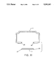
- FIG. 7 shows the image captured by the image splitter of FIG. 1, as seen on a television monitor connected thereto;
- FIG. 8 is a perspective view of the camera mounting assembly of the image splitter of FIG. 1;
- FIG. 9 shows the bevels of the front edges of the mirror pair of the image splitter of FIG. 1;
- FIG. 9A shows the bevels of the edges on mirrors which are spaced apart
- FIG. 10 shows the means of assembling the platform and the camera mounting block of the image splitter of FIG. 1;
- FIG. 11 is a front view showing the platform and housing of the image splitter of FIG. 1.
- the image splitter 1 comprises a housing 2, a platform 3, and an angled mirror assembly 22 and a camera mounting block 13 mounted on the platform 3.
- the camera mounting block 13 comprises a television camera 4 and a lens 5.
- a CHINON CX-500 CCD type security camera and lens are used, although the image splitter 1 can be designed to accommodate a broad range of security cameras and lenses within the spirit and scope of the invention.
- the angled mirror assembly 22 is mounted on a front end of the platform 3 such that a mirror pair 6 of the mirror assembly 22 faces the camera 4.
- a mirror pair 6 of the mirror assembly 22 faces the camera 4.
- FIG. 6 the juxtaposition of the camera 4 and the mirror assembly 22 enables a left image 26 and a right image 27 to be captured simultaneously by the camera 4 as a split screen image, which is shown in FIG. 7.
- the platform 3 is mounted in the housing 2, which provides a window pair 16 so as to allow the left image 26 and the right image 27 to be viewed by the camera 4 via the angled mirror assembly 22.
- the pair of shaped metallic mirrors 6 comprises a left mirror 23 and a right mirror 24 which are mounted on the mirror assembly 22.
- the left mirror 23 and the right mirror 24 are bevelled at their front edges 28 and 29, respectively, as shown in FIG. 9A, in order to form a corner 30 at an angle between approximately 60° and 120°, preferably 90°, to each other as shown in FIG. 9 .
- the mirror pair 6 is attached to a pair of mirror mounting leading edge walls 8, which in turn are held in place by a pair of triangular block assemblies 9.
- the triangular block assemblies 9 are each joined to opposite sides of a hinge 12.
- the sleeve of the hinge 12 is inserted over a pin 7, the position of which can be selected by insertion into any of a plurality of holes 18 in the platform 3.
- the pin 7 provides location and support for the hinge 12 such that the mirror pair 6 will deliver the left image 26 and the right image 27 to the camera 4.
- corner 30 will be formed. This will allow the camera 4 to capture and focus on only the left image 26 and the right image 27 as shown in FIG. 7 and will not be affected by an image of the corner 30 of the mirror pair 6. This functions to maximize the focusing features of the camera 4.
- FIGS. 3 and 8 depict a camera mounting block 13, which is comprised of a flat bottom portion 31 of generally rectangular shape for supporting the camera 4, and a flat front face 32 joined to the bottom portion 31 at a 90° angle.
- the front face 32 comprises a mounting hole 20, through which a threaded collar 21 is held in place by three tabs 14.
- the collar 21 comprises two sets of threads; an external set 33 matched to a standard C-mount in size, shape and dimension; and an internal set 34 matched to a lens 5 to be used in the particular installation.
- the collar 21 is threaded onto the C-mount lens cavity of the camera 4 and is then inserted into the mounting hole 20.
- the tabs 14 are then installed with associated hold down screws 15 so as to firmly hold the collar 21 within the mounting hole 20.
- the lens 5 is then threaded onto the opposite side of the collar 21. In this fashion, the camera 4 and lens 5 are securely fastened to the mounting block 13.
- the dimensions utilized in the preferred embodiment for the above described manner of mounting the camera 4 are as follows.
- the front face 32 is approximately 2.16 inches in height, 2.24 inches in width and 0.375 inches thick.
- the inside diameter of the collar 21 is approximately 1.477 inches, and the outside diameter is approximately 1.737 inches.
- the platform 3 comprises a groove 11 positioned as shown in FIG. 10.
- the mounting block 13 is secured to the platform 3 with hold down screws inserted from the underside of the platform 3, through the groove 11, and into threaded holes 19 on the underside of the bottom portion 31.
- the use of the groove 11 allows the mounting block 13, and therefore the camera 4, to be aligned slidably along the platform 3 as desired. While this manner of mounting the camera 4 is implemented in the preferred embodiment, it is understood that any means known in the art for attaching the camera 4 to the platform 3 or the housing 2 can be used.
- the assembled platform 3 can then be inserted into the housing 2 as follows.
- the housing 2 is generally rectangular in shape and comprises a window pair 16 located at the front portion thereof.
- the assembled platform 3 is slidably mounted inside the housing 2 by means of tracks 35 and 36 thereon, which engage flanged edges 37 and 38 of the platform 3, respectively.
- the platform 3 is then secured to the housing 2 by means by conventional hold down screws. Once secured, the left image 26 and the right image 27 are transmitted through the window pair 16 and reflected by the mirror pair 6 to the lens 5 and the camera 4.
- the length of the housing 2 is approximately 8.625 inches long, the outside width is approximately 5 inches, and the depth at the open end is approximately 2.75 inches.
- the platform 3 is approximately 3 inches wide and 7.625 inches long.
Abstract
Disclosed is an apparatus for providing a pair of images to a fixed security camera, the apparatus comprising an angled mirror assembly comprising a left mirror and a right mirror joined at an edge therebetween and disposed at an angle between approximately 60° and 120°, preferably 90°, to each other. The mirrors are mounted on the angled mirror assembly such that images transmitted through each of a pair of windows of a housing are reflected by the mirrors towards a camera assembly, and the mirrors are bevelled at a joining edge such that no image is generated from the area within and between the respective surfaces thereof. As a result, a left image incident upon the left mirror is reflected thereby towards the camera, and a right image incident upon the right mirror is reflected thereby towards the camera, and the resultant image captured by said camera is composed of a split image of the left image and the right image.
Description
The present invention relates generally to video surveillance systems, and in particular to the use of a pair of mirrors fixed at a predetermined angle in relation to the lens of a television security camera to provide simultaneously a fixed split image of an area under surveillance thereto.
In the field of video surveillance, it is desired to provide the maximum amount of surveillance of the secured area with the minimum amount and complexity of security camera equipment. Television security cameras are often mounted in fixed positions at locations which provide the greatest possible viewing area per camera. When corridors intersect, it is common practice to install two or more cameras in fixed positions at the intersection, with each camera pointed towards a different corridor. In addition, when a long corridor must be monitored, it is common to utilize multiple cameras in fixed positions at various points thereof.
In order to monitor each of the images from the various cameras, it is necessary to provide means for switching from the image provided by one camera to the next. Alternatively, multiple video monitors can be used, corresponding to the number of cameras in the system. Both these methods of monitoring the large number of images provided by the various fixed point cameras are, however, costly.
An alternative way to provide greater coverage is to provide a security camera with means for panning the area under surveillance, rather than fixing the camera in one position. To accomplish this, servo motor drive assemblies are implemented with automatic pan or remote control mechanisms. Typically, a security guard located at a strategically located guard station will operate such remote control devices.
In addition, numerous devices exist in the prior art which operate to move assemblies of mirrors and prisms in order to provide a fixed position security camera with greater surveillance capability. Such mechanisms are also costly and must be aligned and serviced in order to maintain the needed reliability.
Although the use of automatic or semi-automatic drive assemblies enables the reduction of the number of security cameras and corresponding monitors, such assemblies are costly to install and maintain. Moreover, the chance of failure of mechanical panning devices is considerably detrimental in high security applications. Further, the use of such prior art techniques provide only one view for transmission to a monitor at any given time.
Accordingly, it is an object of the present invention to provide video surveillance of a large area with minimal cost and chance of failure.
It is a further object of the present invention to enable a security camera to monitor optical images from two directions simultaneously, thus eliminating the need for mechanical devices which scan areas of a geometrical size too large or of too complex a structure for one security camera to capture.
It is a further object of the present invention to provide an attachment for a standard commercially available security camera to generate separate images of different areas for simultaneous display on a standard commercially available monitor without additional electronic modifications thereto.
In accordance with these and other objects, the present invention is an apparatus for providing a pair of images to a fixed security camera. The apparatus has a housing, a platform slidably engaged within the housing, a camera assembly, and an angled mirror assembly comprising a pair of mirrors. The housing has a pair of windows situated on opposite sides thereof. The camera assembly comprises a camera mounting block, a camera and a lens, with the camera mounting block comprising a ring threaded on a first side for coupling to the mount of the camera and threaded on a second side for coupling to the lens and a plurality of tabs for attaching the ring to the mounting block. The angled mirror assembly has a pair of mirrors comprising a left mirror and a right mirror joined at an edge therebetween and disposed at an angle between approximately 60° and 120°, preferably 90°, to each other. The mirrors are mounted on the angled mirror assembly such that images transmitted through each of the windows of the housing are reflected by the mirrors towards the camera, and the mirrors are bevelled at the joining edge such that no image is generated from the area within and between the respective surfaces thereof. As a result, a left image incident upon the left mirror is reflected thereby towards the camera, and a right image incident upon the right mirror is reflected thereby towards the camera, and the resultant image captured by said camera is composed of a split image of the left image and the right image.
FIG. 1 is a partially exploded perspective view of the image splitter of the present invention;
FIG. 2 is a top plan view of the assembled platform of the image splitter of FIG. 1;
FIG. 3 is a side view of the image splitter of FIG. 1;
FIG. 4 is a top plan view of the housing of the image splitter of FIG. 1;
FIG. 5 is a side view of the housing of the image splitter of FIG. 1;
FIG. 6 is a pictorial of the image capture of the image splitter of FIG. 1;
FIG. 7 shows the image captured by the image splitter of FIG. 1, as seen on a television monitor connected thereto;
FIG. 8 is a perspective view of the camera mounting assembly of the image splitter of FIG. 1;
FIG. 9 shows the bevels of the front edges of the mirror pair of the image splitter of FIG. 1;
FIG. 9A shows the bevels of the edges on mirrors which are spaced apart;
FIG. 10 shows the means of assembling the platform and the camera mounting block of the image splitter of FIG. 1; and
FIG. 11 is a front view showing the platform and housing of the image splitter of FIG. 1.
The preferred embodiment of the image splitter 1 of the present invention will now be described in detail. Referring generally to FIGS. 1, 2 and 3, the image splitter 1 comprises a housing 2, a platform 3, and an angled mirror assembly 22 and a camera mounting block 13 mounted on the platform 3. The camera mounting block 13 comprises a television camera 4 and a lens 5. In the preferred embodiment, a CHINON CX-500 CCD type security camera and lens are used, although the image splitter 1 can be designed to accommodate a broad range of security cameras and lenses within the spirit and scope of the invention.
The angled mirror assembly 22 is mounted on a front end of the platform 3 such that a mirror pair 6 of the mirror assembly 22 faces the camera 4. As can be seen from FIG. 6, the juxtaposition of the camera 4 and the mirror assembly 22 enables a left image 26 and a right image 27 to be captured simultaneously by the camera 4 as a split screen image, which is shown in FIG. 7. The platform 3 is mounted in the housing 2, which provides a window pair 16 so as to allow the left image 26 and the right image 27 to be viewed by the camera 4 via the angled mirror assembly 22.
The pair of shaped metallic mirrors 6 comprises a left mirror 23 and a right mirror 24 which are mounted on the mirror assembly 22. The left mirror 23 and the right mirror 24 are bevelled at their front edges 28 and 29, respectively, as shown in FIG. 9A, in order to form a corner 30 at an angle between approximately 60° and 120°, preferably 90°, to each other as shown in FIG. 9 . The mirror pair 6 is attached to a pair of mirror mounting leading edge walls 8, which in turn are held in place by a pair of triangular block assemblies 9. The triangular block assemblies 9 are each joined to opposite sides of a hinge 12. The sleeve of the hinge 12 is inserted over a pin 7, the position of which can be selected by insertion into any of a plurality of holes 18 in the platform 3. Thus, the pin 7 provides location and support for the hinge 12 such that the mirror pair 6 will deliver the left image 26 and the right image 27 to the camera 4.
By bevelling and joining tightly the front edges of the left mirror 23 and the right mirror 24 of the mirror pair 6 to the appropriate angle, as shown in detail in FIG. 9, corner 30 will be formed. This will allow the camera 4 to capture and focus on only the left image 26 and the right image 27 as shown in FIG. 7 and will not be affected by an image of the corner 30 of the mirror pair 6. This functions to maximize the focusing features of the camera 4.
The camera 4 is mounted to the platform 3 in the following manner. FIGS. 3 and 8 depict a camera mounting block 13, which is comprised of a flat bottom portion 31 of generally rectangular shape for supporting the camera 4, and a flat front face 32 joined to the bottom portion 31 at a 90° angle. The front face 32 comprises a mounting hole 20, through which a threaded collar 21 is held in place by three tabs 14. The collar 21 comprises two sets of threads; an external set 33 matched to a standard C-mount in size, shape and dimension; and an internal set 34 matched to a lens 5 to be used in the particular installation. The collar 21 is threaded onto the C-mount lens cavity of the camera 4 and is then inserted into the mounting hole 20. The tabs 14 are then installed with associated hold down screws 15 so as to firmly hold the collar 21 within the mounting hole 20. The lens 5 is then threaded onto the opposite side of the collar 21. In this fashion, the camera 4 and lens 5 are securely fastened to the mounting block 13.
The dimensions utilized in the preferred embodiment for the above described manner of mounting the camera 4 are as follows. The front face 32 is approximately 2.16 inches in height, 2.24 inches in width and 0.375 inches thick. The inside diameter of the collar 21 is approximately 1.477 inches, and the outside diameter is approximately 1.737 inches. By securing the camera 4 and the lens 5 to the mounting block 13 in the above described manner, convenient interchangeability of lenses and cameras is obtained.
The platform 3 comprises a groove 11 positioned as shown in FIG. 10. The mounting block 13 is secured to the platform 3 with hold down screws inserted from the underside of the platform 3, through the groove 11, and into threaded holes 19 on the underside of the bottom portion 31. The use of the groove 11 allows the mounting block 13, and therefore the camera 4, to be aligned slidably along the platform 3 as desired. While this manner of mounting the camera 4 is implemented in the preferred embodiment, it is understood that any means known in the art for attaching the camera 4 to the platform 3 or the housing 2 can be used.
Referring to FIGS. 1, 4, 5, and 11, the assembled platform 3 can then be inserted into the housing 2 as follows. The housing 2 is generally rectangular in shape and comprises a window pair 16 located at the front portion thereof. The assembled platform 3 is slidably mounted inside the housing 2 by means of tracks 35 and 36 thereon, which engage flanged edges 37 and 38 of the platform 3, respectively. The platform 3 is then secured to the housing 2 by means by conventional hold down screws. Once secured, the left image 26 and the right image 27 are transmitted through the window pair 16 and reflected by the mirror pair 6 to the lens 5 and the camera 4.
In the preferred embodiment, the length of the housing 2 is approximately 8.625 inches long, the outside width is approximately 5 inches, and the depth at the open end is approximately 2.75 inches. The platform 3 is approximately 3 inches wide and 7.625 inches long.
Although preferred embodiments of the invention have been described in the foregoing detailed description and illustrated in the accompanying drawings, it will be understood that the invention is not limited to the embodiments disclosed, but is capable of numerous rearrangements, modifications and substitutions of parts and elements without departing from the spirit of the invention. Accordingly, the present invention is intended to encompass such rearrangements, modifications and substitutions of parts and elements as fall within the spirit and scope of the appended claims.
Claims (4)
1. An image splitting optical system an image splitting optical system comprising:
(a) a platform;
(b) optical means secured to said platform and disposed thereon to provide simultaneously to a camera a plurality of images; and
(c) means for securing a camera to said platform and further comprising a housing for enclosing said platform, said housing comprising a pair of windows disposed to enable transmission of images therethrough; and wherein said optical means comprises a pair of mirrors joined at an edge and disposed at an angle between approximately 60° and 120° to each other, said mirrors mounted on a mirror mounting means such that images transmitted through each of said windows of said housing are reflected by said mirrors towards said camera;
and wherein said mirrors are bevelled at said joining edges and fitted together at said joining edge such that no image is generated from the area within and between the respective surfaces thereof and wherein said mirror mounting means comprises a hinged mounting assembly attached to said mirrors, a pin inserted through said hinged mounting assembly and into one of a plurality of alignment holes on said platform, such that said mirror mounting means can be secured to any of a number of fixed positions on said platform and the position thereof can be adjusted as desired.
2. The image splitting optical system of claim 1 wherein said means for securing a camera to a platform comprise a ring threaded on a first side for coupling to the mount of a camera and threaded on a second side for coupling to a lens, and means for attaching said ring to said securing means.
3. The image splitting optical system of claim 2 further comprising a camera and a lens attached to said means for securing a camera.
4. An apparatus for providing a pair of images to a fixed security camera, said apparatus comprising:
(a) a housing comprising a pair of windows situated on opposite sides thereof;
(b) a platform slidably engaged within said housing;
(c) a camera assembly comprising a camera mounting block, a camera and a lens, said camera mounting block comprising a ring threaded on a first side for coupling to the mount of the camera and threaded on a second side for coupling to the lens, and a plurality of tabs for attaching said ring to said mounting block, wherein said camera assembly is slidably mounted along a groove of said platform; and
(d) an angled mirror assembly comprising a pair of mirrors comprising a left mirror and a right mirror joined at an edge therebetween and disposed at approximately 90° to each other, said mirrors mounted on said angled mirror assembly such that images transmitted through each of said windows of said housing are reflected by said mirrors towards said camera, said mirrors bevelled at a joining edge such that no image is generated from the area within and between the respective surfaces thereof;
whereby a left image incident upon the left mirror is reflected thereby at approximately a 90° angle towards said camera, and a right image incident upon the right mirror is reflected thereby at approximately a 90° angle towards said camera, and the resultant image captured by said camera is composed of a split image of the left image and the right image.
Priority Applications (3)
| Application Number | Priority Date | Filing Date | Title |
|---|---|---|---|
| US07/871,440 US5293243A (en) | 1992-04-21 | 1992-04-21 | Image splitter for security cameras |
| PCT/US1993/003661 WO1993021736A1 (en) | 1992-04-21 | 1993-04-19 | Image splitter for security cameras and the like |
| AU41069/93A AU4106993A (en) | 1992-04-21 | 1993-04-19 | Image splitter for security cameras and the like |
Applications Claiming Priority (1)
| Application Number | Priority Date | Filing Date | Title |
|---|---|---|---|
| US07/871,440 US5293243A (en) | 1992-04-21 | 1992-04-21 | Image splitter for security cameras |
Publications (1)
| Publication Number | Publication Date |
|---|---|
| US5293243A true US5293243A (en) | 1994-03-08 |
Family
ID=25357437
Family Applications (1)
| Application Number | Title | Priority Date | Filing Date |
|---|---|---|---|
| US07/871,440 Expired - Fee Related US5293243A (en) | 1992-04-21 | 1992-04-21 | Image splitter for security cameras |
Country Status (1)
| Country | Link |
|---|---|
| US (1) | US5293243A (en) |
Cited By (11)
| Publication number | Priority date | Publication date | Assignee | Title |
|---|---|---|---|---|
| EP0750219A1 (en) * | 1995-06-22 | 1996-12-27 | Niles Parts Co., Ltd. | Multi-direction camera |
| EP0751041A2 (en) * | 1995-06-27 | 1997-01-02 | Yoshihisa Furuta | Device for checking lateral views at front/rear ends of a vehicle |
| US6064430A (en) * | 1995-12-11 | 2000-05-16 | Slc Technologies Inc. | Discrete surveillance camera devices |
| KR20020001553A (en) * | 2000-06-22 | 2002-01-09 | 다니구찌 이찌로오, 기타오카 다카시 | Image pick-up apparatus and portable telephone utilizing the same |
| US8316536B1 (en) | 2002-05-01 | 2012-11-27 | Amkor Technology, Inc. | Multi-level circuit substrate fabrication method |
| US8826531B1 (en) | 2005-04-05 | 2014-09-09 | Amkor Technology, Inc. | Method for making an integrated circuit substrate having laminated laser-embedded circuit layers |
| US8872329B1 (en) | 2009-01-09 | 2014-10-28 | Amkor Technology, Inc. | Extended landing pad substrate package structure and method |
| US9812386B1 (en) | 2002-05-01 | 2017-11-07 | Amkor Technology, Inc. | Encapsulated semiconductor package |
| US10811277B2 (en) | 2004-03-23 | 2020-10-20 | Amkor Technology, Inc. | Encapsulated semiconductor package |
| US11081370B2 (en) | 2004-03-23 | 2021-08-03 | Amkor Technology Singapore Holding Pte. Ltd. | Methods of manufacturing an encapsulated semiconductor device |
| US11094560B1 (en) | 2004-03-23 | 2021-08-17 | Amkor Technology Singapore Holding Pte. Ltd. | Encapsulated semiconductor package |
Citations (22)
| Publication number | Priority date | Publication date | Assignee | Title |
|---|---|---|---|---|
| US1334810A (en) * | 1919-12-06 | 1920-03-23 | Jr Alexander Smith | Foot-pressure reflector |
| US2109586A (en) * | 1936-05-12 | 1938-03-01 | Einbinder Harry | Display stand |
| US2261940A (en) * | 1941-03-22 | 1941-11-11 | James E Palmer | Safety device |
| US3254933A (en) * | 1963-10-24 | 1966-06-07 | E D L Dimension Inc | Movie camera |
| US3546378A (en) * | 1966-12-20 | 1970-12-08 | Asahi Optical Co Ltd | Televising and photographing apparatus |
| US3610825A (en) * | 1969-06-04 | 1971-10-05 | Hughes Aircraft Co | Image control apparatus for a vision system |
| US3634622A (en) * | 1969-06-04 | 1972-01-11 | Hughes Aircraft Co | Remote view and direct view camera-pointing system |
| US3900243A (en) * | 1973-06-25 | 1975-08-19 | Moderna Butiksinredningar Ab | Watching mirror |
| US3952217A (en) * | 1973-09-25 | 1976-04-20 | The Perkin-Elmer Corporation | Drive for scanning mirror |
| US4024733A (en) * | 1976-02-20 | 1977-05-24 | The Singer Company | Multiple pattern wheel |
| US4047792A (en) * | 1975-12-31 | 1977-09-13 | Hughes Aircraft Company | Torque while turn-around scan mirror assembly |
| US4058831A (en) * | 1976-09-08 | 1977-11-15 | Lectrolarm Custom Systems, Inc. | Panoramic camera scanning system |
| US4266847A (en) * | 1977-12-10 | 1981-05-12 | Elektro-Optik Gmbh & Co. Kg | Apparatus for line-scanning of large image fields |
| US4326218A (en) * | 1980-11-14 | 1982-04-20 | Coutta John M | Surveillance system |
| US4364000A (en) * | 1975-08-29 | 1982-12-14 | Mfe Corporation | Limited rotation device having two degrees of freedom |
| GB2103824A (en) * | 1981-08-20 | 1983-02-23 | Marconi Co Ltd | Scanning mirror systems |
| US4410233A (en) * | 1981-05-07 | 1983-10-18 | Honeywell Inc. | Unequal four-bar linkage scan mirror assembly |
| US4437745A (en) * | 1982-09-30 | 1984-03-20 | Stephen Hajnal | Three dimensional camera system |
| US4499490A (en) * | 1982-05-10 | 1985-02-12 | Morgan Jack B | Scanning apparatus with video camera |
| US4750486A (en) * | 1985-08-14 | 1988-06-14 | Butler Philip H | Apparatus for moving a mirror |
| US4792198A (en) * | 1987-06-18 | 1988-12-20 | Spectra-Physics, Inc. | Method and apparatus for rotating one or more mirrors in a beam scanning system |
| US4941739A (en) * | 1989-01-17 | 1990-07-17 | University Of British Columbia | Mirror scanner |
-
1992
- 1992-04-21 US US07/871,440 patent/US5293243A/en not_active Expired - Fee Related
Patent Citations (22)
| Publication number | Priority date | Publication date | Assignee | Title |
|---|---|---|---|---|
| US1334810A (en) * | 1919-12-06 | 1920-03-23 | Jr Alexander Smith | Foot-pressure reflector |
| US2109586A (en) * | 1936-05-12 | 1938-03-01 | Einbinder Harry | Display stand |
| US2261940A (en) * | 1941-03-22 | 1941-11-11 | James E Palmer | Safety device |
| US3254933A (en) * | 1963-10-24 | 1966-06-07 | E D L Dimension Inc | Movie camera |
| US3546378A (en) * | 1966-12-20 | 1970-12-08 | Asahi Optical Co Ltd | Televising and photographing apparatus |
| US3610825A (en) * | 1969-06-04 | 1971-10-05 | Hughes Aircraft Co | Image control apparatus for a vision system |
| US3634622A (en) * | 1969-06-04 | 1972-01-11 | Hughes Aircraft Co | Remote view and direct view camera-pointing system |
| US3900243A (en) * | 1973-06-25 | 1975-08-19 | Moderna Butiksinredningar Ab | Watching mirror |
| US3952217A (en) * | 1973-09-25 | 1976-04-20 | The Perkin-Elmer Corporation | Drive for scanning mirror |
| US4364000A (en) * | 1975-08-29 | 1982-12-14 | Mfe Corporation | Limited rotation device having two degrees of freedom |
| US4047792A (en) * | 1975-12-31 | 1977-09-13 | Hughes Aircraft Company | Torque while turn-around scan mirror assembly |
| US4024733A (en) * | 1976-02-20 | 1977-05-24 | The Singer Company | Multiple pattern wheel |
| US4058831A (en) * | 1976-09-08 | 1977-11-15 | Lectrolarm Custom Systems, Inc. | Panoramic camera scanning system |
| US4266847A (en) * | 1977-12-10 | 1981-05-12 | Elektro-Optik Gmbh & Co. Kg | Apparatus for line-scanning of large image fields |
| US4326218A (en) * | 1980-11-14 | 1982-04-20 | Coutta John M | Surveillance system |
| US4410233A (en) * | 1981-05-07 | 1983-10-18 | Honeywell Inc. | Unequal four-bar linkage scan mirror assembly |
| GB2103824A (en) * | 1981-08-20 | 1983-02-23 | Marconi Co Ltd | Scanning mirror systems |
| US4499490A (en) * | 1982-05-10 | 1985-02-12 | Morgan Jack B | Scanning apparatus with video camera |
| US4437745A (en) * | 1982-09-30 | 1984-03-20 | Stephen Hajnal | Three dimensional camera system |
| US4750486A (en) * | 1985-08-14 | 1988-06-14 | Butler Philip H | Apparatus for moving a mirror |
| US4792198A (en) * | 1987-06-18 | 1988-12-20 | Spectra-Physics, Inc. | Method and apparatus for rotating one or more mirrors in a beam scanning system |
| US4941739A (en) * | 1989-01-17 | 1990-07-17 | University Of British Columbia | Mirror scanner |
Cited By (18)
| Publication number | Priority date | Publication date | Assignee | Title |
|---|---|---|---|---|
| EP0750219A1 (en) * | 1995-06-22 | 1996-12-27 | Niles Parts Co., Ltd. | Multi-direction camera |
| KR100360322B1 (en) * | 1995-06-22 | 2003-03-28 | 나이루스 부힝 가부시키가이샤 | Multidirectional camera device |
| EP0751041A2 (en) * | 1995-06-27 | 1997-01-02 | Yoshihisa Furuta | Device for checking lateral views at front/rear ends of a vehicle |
| EP0751041A3 (en) * | 1995-06-27 | 1998-01-07 | Yoshihisa Furuta | Device for checking lateral views at front/rear ends of a vehicle |
| US6064430A (en) * | 1995-12-11 | 2000-05-16 | Slc Technologies Inc. | Discrete surveillance camera devices |
| US6249310B1 (en) | 1995-12-11 | 2001-06-19 | Slc Technologies Inc. | Discrete surveillance camera devices |
| KR20020001553A (en) * | 2000-06-22 | 2002-01-09 | 다니구찌 이찌로오, 기타오카 다카시 | Image pick-up apparatus and portable telephone utilizing the same |
| US8322030B1 (en) * | 2002-05-01 | 2012-12-04 | Amkor Technology, Inc. | Circuit-on-foil process for manufacturing a laminated semiconductor package substrate having embedded conductive patterns |
| US8316536B1 (en) | 2002-05-01 | 2012-11-27 | Amkor Technology, Inc. | Multi-level circuit substrate fabrication method |
| US9812386B1 (en) | 2002-05-01 | 2017-11-07 | Amkor Technology, Inc. | Encapsulated semiconductor package |
| US10461006B1 (en) | 2002-05-01 | 2019-10-29 | Amkor Technology, Inc. | Encapsulated semiconductor package |
| US10811277B2 (en) | 2004-03-23 | 2020-10-20 | Amkor Technology, Inc. | Encapsulated semiconductor package |
| US11081370B2 (en) | 2004-03-23 | 2021-08-03 | Amkor Technology Singapore Holding Pte. Ltd. | Methods of manufacturing an encapsulated semiconductor device |
| US11094560B1 (en) | 2004-03-23 | 2021-08-17 | Amkor Technology Singapore Holding Pte. Ltd. | Encapsulated semiconductor package |
| US8826531B1 (en) | 2005-04-05 | 2014-09-09 | Amkor Technology, Inc. | Method for making an integrated circuit substrate having laminated laser-embedded circuit layers |
| US11848214B2 (en) | 2006-08-01 | 2023-12-19 | Amkor Technology Singapore Holding Pte. Ltd. | Encapsulated semiconductor package |
| US8872329B1 (en) | 2009-01-09 | 2014-10-28 | Amkor Technology, Inc. | Extended landing pad substrate package structure and method |
| US9462704B1 (en) | 2009-01-09 | 2016-10-04 | Amkor Technology, Inc. | Extended landing pad substrate package structure and method |
Similar Documents
| Publication | Publication Date | Title |
|---|---|---|
| US5293243A (en) | Image splitter for security cameras | |
| US6375369B1 (en) | Housing for a surveillance camera | |
| US4288819A (en) | Multi-field imaging device | |
| US20100045773A1 (en) | Panoramic adapter system and method with spherical field-of-view coverage | |
| US20080079809A1 (en) | Surveillance camera and surveillance camera system with laser positioning function | |
| AU2013204513A1 (en) | A camera | |
| US9936112B2 (en) | Monitoring camera | |
| US4740839A (en) | TV surveillance system that requires no mechanical motion | |
| KR100633033B1 (en) | Fan/tilt camera apparatus with auxiliary camera | |
| US6731845B1 (en) | Panoramic visual system for non-rotating structures | |
| JPH0993471A (en) | Panorama television camera and video monitor | |
| US4355329A (en) | Remote station | |
| US4407009A (en) | Retrofitting a televised output device on a thermal imager | |
| WO2008037127A1 (en) | Monitoring camera and monitoring system having function of laser positioning | |
| WO1993021736A1 (en) | Image splitter for security cameras and the like | |
| US6784937B1 (en) | Lens assembly of digital camera with non-step focusing function | |
| KR100360694B1 (en) | A device and a arrangement method of sector lens for panorama image | |
| US11838653B2 (en) | Wide-angle streaming multi-camera system | |
| CN213522086U (en) | Intelligent monitoring system based on 360-degree panoramic camera | |
| Butterfield | Very high resolution stereoscopic television | |
| US4646146A (en) | Surveillance camera device with automatically controlled shutter | |
| EP0829073B1 (en) | Surveillance system | |
| JP3230276B2 (en) | Module type surveillance camera | |
| KR20020039182A (en) | Dome camera | |
| US20080143836A1 (en) | Video surveillance camera with covert field of view |
Legal Events
| Date | Code | Title | Description |
|---|---|---|---|
| REMI | Maintenance fee reminder mailed | ||
| AS | Assignment |
Owner name: STONE, HENRY LEE, ILLINOIS Free format text: ASSIGNMENT OF ASSIGNORS INTEREST;ASSIGNORS:DEGNAN, DONALD E.;SCHAAD, HOWARD A.;REEL/FRAME:009015/0826 Effective date: 19980203 |
|
| FPAY | Fee payment |
Year of fee payment: 4 |
|
| SULP | Surcharge for late payment | ||
| FPAY | Fee payment |
Year of fee payment: 8 |
|
| REMI | Maintenance fee reminder mailed | ||
| LAPS | Lapse for failure to pay maintenance fees | ||
| STCH | Information on status: patent discontinuation |
Free format text: PATENT EXPIRED DUE TO NONPAYMENT OF MAINTENANCE FEES UNDER 37 CFR 1.362 |
|
| FP | Lapsed due to failure to pay maintenance fee |
Effective date: 20060308 |